

Page 1
Rosemount™ 700XA
Gas Chromatograph
Reference Manual
2-3-9000-744, Rev L
June 2022
Page 2

Notice
EMERSON (“SELLER”) SHALL NOT BE LIABLE FOR TECHNICAL OR EDITORIAL ERRORS IN THIS MANUAL OR OMISSIONS FROM THIS
MANUAL. SELLER MAKES NO WARRANTIES, EXPRESSED OR IMPLIED, INCLUDING THE IMPLIED WARRANTIES OF
MERCHANTABILITY AND FITNESS FOR A PARTICULAR PURPOSE, WITH RESPECT TO THIS MANUAL AND, IN NO EVENT, SHALL
SELLER BE LIABLE FOR ANY SPECIAL OR CONSEQUENTIAL DAMAGES INCLUDING, BUT NOT LIMITED TO, LOSS OF PRODUCTION,
LOSS OF PROFITS, ETC.
PRODUCT NAMES USED HEREIN ARE FOR MANUFACTURER OR SUPPLIER IDENTIFICATION ONLY AND MAY BE TRADEMARKS/
REGISTERED TRADEMARKS OF THESE COMPANIES.
THE CONTENTS OF THIS PUBLICATION ARE PRESENTED FOR INFORMATIONAL PURPOSES ONLY AND, WHILE EVERY EFFORT HAS
BEEN MADE TO ENSURE THEIR ACCURACY, THEY ARE NOT TO BE CONSTRUED AS WARRANTIES OR GUARANTEES, EXPRESSED OR
IMPLIED, REGARDING THE PRODUCTS OR SERVICES DESCRIBED HEREIN OR THEIR USE OR APPLICABILITY. WE RESERVE THE RIGHT
TO MODIFY OR IMPROVE THE DESIGNS OR SPECIFICATIONS OF SUCH PRODUCTS AT ANY TIME.
SELLER DOES NOT ASSUME RESPONSIBILITY FOR THE SELECTION, USE, OR MAINTENANCE OF ANY PRODUCT. RESPONSIBILITY FOR
PROPER SELECTION, USE, AND MAINTENANCE OF ANY SELLER PRODUCT REMAINS SOLELY WITH THE PURCHASER AND END-USER.
Warranty
LIMITED WARRANTY: Subject to the limitations contained in Section 2 herein and except as otherwise expressly provided
1.
herein, Emerson (“Seller”) warrants that the firmware will execute the programming instructions provided by Seller and
that the Goods manufactured or Services provided by Seller will be free from defects in materials or workmanship under
normal use and care until the expiration of the applicable warranty period. Goods are warranted for twelve (12) months
from the date of initial installation or eighteen (18) months from the date of shipment by Seller, whichever period expires
first. Consumables and Services are warranted for a period of 90 days from the date of shipment or completion of the
Services. Products purchased by Seller from a third party for resale to Buyer (“Resale Products”) shall carry only the
warranty extended by the original manufacturer. Buyer agrees that Seller has no liability for Resale Products beyond
making a reasonable commercial effort to arrange for procurement and shipping of the Resale Products. If Buyer
discovers any warranty defects and notifies Seller thereof in writing during the applicable warranty period, Seller shall, at
its option, promptly correct any errors that are found by Seller in the firmware or Services, or repair or replace F.O.B. point
of manufacture that portion of the Goods or firmware found by Seller to be defective, or refund the purchase price of the
defective portion of the Goods/Services. All replacements or repairs necessitated by inadequate maintenance, normal
wear and usage, unsuitable power sources, unsuitable environmental conditions, accident, misuse, improper installation,
modification, repair, storage or handling, or any other cause not the fault of Seller are not covered by this limited
warranty, and shall be at Buyer's expense. Seller shall not be obligated to pay any costs or charges incurred by Buyer or any
other party except as may be agreed upon in writing in advance by an authorized Seller representative. All costs of
dismantling, reinstallation and freight, and the time and expenses of Seller's personnel for site travel and diagnosis under
this warranty clause shall be borne by Buyer unless accepted in writing by Seller. Goods repaired and parts replaced during
the warranty period shall be in warranty for the remainder of the original warranty period or ninety (90) days, whichever is
longer. This limited warranty is the only warranty made by Seller and can be amended only in a writing signed by an
authorized representative of Seller. Except as otherwise expressly provided in the Agreement, THERE ARE NO
REPRESENTATIONS OR WARRANTIES OF ANY KIND, EXPRESSED OR IMPLIED, AS TO MERCHANTABILITY, FITNESS FOR
PARTICULAR PURPOSE, OR ANY OTHER MATTER WITH RESPECT TO ANY OF THE GOODS OR SERVICES. It is understood
that corrosion or erosion of materials is not covered by our guarantee.
LIMITATION OF REMEDY AND LIABILITY: SELLER SHALL NOT BE LIABLE FOR DAMAGES CAUSED BY DELAY IN
2.
PERFORMANCE. THE SOLE AND EXCLUSIVE REMEDY FOR BREACH OF WARRANTY HEREUNDER SHALL BE LIMITED TO
REPAIR, CORRECTION, REPLACEMENT, OR REFUND OF PURCHASE PRICE UNDER THE LIMITED WARRANTY CLAUSE IN
SECTION 1 HEREIN. IN NO EVENT, REGARDLESS OF THE FORM OF THE CLAIM OR CAUSE OF ACTION (WHETHER BASED IN
CONTRACT, INFRINGEMENT, NEGLIGENCE, STRICT LIABILITY, OTHER TORT, OR OTHERWISE), SHALL SELLER'S LIABILITY TO
BUYER AND/OR ITS CUSTOMERS EXCEED THE PRICE TO BUYER OF THE SPECIFIC GOODS MANUFACTURED OR SERVICES
PROVIDED BY SELLER GIVING RISE TO THE CLAIM OR CAUSE OF ACTION. BUYER AGREES THAT IN NO EVENT SHALL
SELLER'S LIABILITY TO BUYER AND/OR ITS CUSTOMERS EXTEND TO INCLUDE INCIDENTAL, CONSEQUENTIAL, OR PUNITIVE
DAMAGES. THE TERM “CONSEQUENTIAL DAMAGES” SHALL INCLUDE, BUT NOT BE LIMITED TO, LOSS OF ANTICIPATED
PROFITS, LOSS OF USE, LOSS OF REVENUE, AND COST OF CAPITAL.
Safety information
NOTICE
The analyzer electronics and oven assembly, when housed inside a purged enclosure, meet the certifications and classifications
identified in the Specifications section of the Product Data Sheet, which is located on the Emerson website: emerson.com.
2
Page 3

WARNING
Safety compliance
Failure to follow the safety instructions may cause injury to personnel. The seller does not accept any responsibility for installations
of the device or any attached equipment in which the installation or operation thereof has been performed in a manner that is
negligent and/or non-compliant with applicable safety requirements.
Install and operate all equipment as designed and comply with all safety requirements.
If the device is not operated in a manner recommended by the manufacturer, the overall safety could be impaired.
Observe all safety precautions defined in the gas Safety Data Sheet (SDS), especially for hazardous locations.
WARNING
Supply mains connection
The device is intended to be connected to supply mains by qualified personnel in accordance with local and national codes.
WARNING
Explosion
Failure to de-energize the analyzer may cause an explosion and severely injure personnel.
Before opening the analyzer, disconnect all electrical power and ensure that the area is free of explosive gases.
Keep cover tight while circuits are live.
Use cables or wires suitable for the marked "T" ratings.
Cover joints must be cleaned before replacing the cover.
Conduit runs to the enclosure must have sealing fitting adjacent to enclosure.
WARNING
Power
A suitable APPROVED switch and fuse or a circuit breaker shall be provided to facilitate the disconnection of mains power.
WARNING
Ventilation
Use the device in a well-ventilated area.
If you plan to place the device in a sealed shelter, always vent it to atmosphere with 0.25 in (6.4 mm) tubing or larger. This will
prevent the build up of H2 and sample gas.
WARNING
Leak testing
All gas connections must be properly leak tested at installation.
Do not turn on gas until you have completely checked the carrier lines for leaks.
WARNING
Precautionary signs
Failure to observe precautionary signs may result in injury or death to personnel or cause damage to equipment.
Observe and comply with all precautionary signs posted on the device.
3
Page 4

WARNING
Toxic vapors
Exit ports may discharge dangerous levels of toxic vapors.
Use proper protection and a suitable exhaust device.
WARNING
Burns
Some parts of the analyzer may be heated to 248 °F (120 °C).
To prevent burns, do not touch any of the hot parts. All parts of an analyzer are always hot unless it has been switched off and
allowed to cool down.
Before fitting, removing, or performing any maintenance on the analyzer, make sure that it has been switched off and allowed
to cool for at least two hours.
When handling the analyzer, always use suitable protective gloves.
These precautions are particularly important when working at heights.
If burned, seek medical treatment immediately.
WARNING
Physical access
Unauthorized personnel may potentially cause significant damage to and/or misconfiguration of end users’ equipment. This could
be intentional or unintentional and needs to be protected against.
Physical security is an important part of any security program and fundamental to protecting your system. Restrict physical access
by unauthorized personnel to protect end users' assets. This is true for all systems used within the facility.
NOTICE
Replaceable parts
Only a few parts inside the device are replaceable. Only trained service personnel should replace parts.
All replacement parts must be authorized by Emerson to ensure product certification compliance.
NOTICE
Equipment damage
If the device is heated without carrier flow, damage to the columns may occur.
NOTICE
Waste disposal
Waste electrical and electronic products must not be disposed of with household waste.
Please recycle where facilities exist.
Check with your local authority or retailer for recycling advice.
NOTICE
The device is certified by CSA and ATEX. See the certification tag on the device for specific details about its agency approvals.
When the vapor regulators and flow switches are fitted, they must be suitably certified with the ratings Ex d IIC Gb T6/T4/T3 and
for a minimum ambient temperature range: Ta = -20 °C to +60 °C.
Where right angle bend cable adapters are used, they shall be appropriately certified and shall interface with enclosures via
appropriate certified barrier glands.
4
Page 5

Glossary
Auto zero
Baseline
Carrier gas
CDT
Chromatogram
Component
CTS
DCD
DSR
DTR
FID
FPD
GC
LSIV
Methanator
PC
Response factor
The thermal conductivity detector (TCD) is auto zeroed at the start of a new analysis. The operator can also
configure automatic zeroing of the TCD amplifier to take place at any time during the analysis if the
component is not eluting or the baseline is steady. The flame ionization detector (FID) will auto zero at each
new analysis run and can be configured to auto zero anytime during the analysis if the component is not
eluting or the baseline is steady.
Signal output when there is only carrier gas going across the detectors. In a chromatogram you should only
see Baseline when running an analysis without injecting a sample.
The gas used to push the sample through the system during an analysis.
Component data table.
A permanent record of the detector output. A chromatogram is obtained from a personal computer (PC)
interfaced with the detector output through the controller assembly. A typical chromatogram displays all
component peaks and gain changes. It may be viewed in color as it is processed on a PC display. Check marks
recorded on the chromatogram by the controller assembly indicate where timed events take place.
Any one of several different gases that may appear in a sample mixture. For example, natural gas usually
contains the following components: nitrogen, carbon dioxide, methane, ethane, propane, isobutane, normal
butane, isopentane, normal pentane, and hexanes plus.
Clear to send.
Data carrier detect.
Data set ready.
Data terminal ready.
Flame ionization detector. The optional FID may be used in place of a TCD for the detection of trace
compounds. The FID requires a polarization voltage, and its output is connected to the input to a high
impedance amplifier, an electrometer. The sample of gas to be measured is injected into the burner with a
mixture of hydrogen and air to maintain the flame.
Flame photometric detector. The FPD is used to analyze gas compound impurities, such as sulfur,
phosphorous, and metals. When sample gas passes through the hydrogen/air flame the component's
wavelengths emitted are electrically measured. The FPD is located in the analyzer's upper enclosure.
Gas chromatograph. The GC is a user-configurable analyzer for various process gas applications.
Liquid sample injection valve. The optional LSIV is used to convert a liquid sample to a gas sample by
vaporizing the liquid in a heated chamber, so the resulting gas sample can be analyzed.
The optional methanator, also known as a catalytic converter, transforms the components that are
undetectable by the FID (carbon dioxide and/or carbon monoxide) into methane by adding hydrogen and
heat to the sample.
Personal computer.
Correction factor for each component as determined by the following calibration:
Retention time
RI
RLSD
RTS
RxD, RD, or S
SCS
TCD
Time, in seconds, that elapses between the start of analysis and the sensing of the maximum concentration of
each component by the detector.
Ring indicator.
Received line signal detect. A digital simulation of a carrier detect.
Request to send.
Receive data or signal in.
in
Sample conditioning system.
Thermal conductivity detector. A detector that uses the thermal conductivity of the different gas
components to produce an unbalanced signal across the bridge of the preamplifier. The higher the
temperature, the lower the resistance on the detectors.
5
Page 6

TxD, TD, or S
Transmit data or signal out.
out
6
Page 7

Reference Manual Contents
2-3-9000-744 June 2022
Contents
Chapter 1 Overview................................................................................................................... 9
1.1 System description...................................................................................................................... 9
1.2 Functional description............................................................................................................... 10
1.3 Software description..................................................................................................................12
1.4 Theory of operation................................................................................................................... 14
Chapter 2 Equipment description and specifications................................................................ 31
2.1 Equipment description.............................................................................................................. 31
2.2 Specifications............................................................................................................................ 39
Chapter 3 Getting started.........................................................................................................43
3.1 Select site.................................................................................................................................. 43
3.2 Unpack the gas chromatograph (GC).........................................................................................43
3.3 Required tools and components................................................................................................ 45
3.4 Supporting tools and components.............................................................................................46
Chapter 4 Installation and start-up .......................................................................................... 47
4.1 Installation considerations.........................................................................................................47
4.2 Mounting arrangements............................................................................................................47
4.3 Gas chromatograph wiring........................................................................................................ 51
4.4 Electrical installation..................................................................................................................55
4.5 Leak checking and purging for first calibration...........................................................................95
4.6 Start up the system....................................................................................................................98
Chapter 5 Operation and maintenance...................................................................................101
5.1 Warning and notice................................................................................................................. 101
5.2 Start a 2-point calibration........................................................................................................ 101
5.3 Troubleshooting and repair..................................................................................................... 102
5.4 Routine maintenance.............................................................................................................. 102
Chapter 6 Troubleshooting.................................................................................................... 183
6.1 Hardware alarms..................................................................................................................... 183
6.2 No power to flame photometric detector (FPD).......................................................................192
6.3 Can't ignite flame photometric detector (FPD)........................................................................ 192
6.4 No peaks showing....................................................................................................................192
6.5 Small peaks..............................................................................................................................193
6.6 No temperature readings.........................................................................................................193
6.7 Noisy baseline..........................................................................................................................193
6.8 Peak clipping........................................................................................................................... 193
6.9 Test points...............................................................................................................................194
6.10 Voltage LEDs..........................................................................................................................195
Rosemount 700XA 7
Page 8

Contents Reference Manual
June 2022 2-3-9000-744
6.11 Monitoring the detector(s) and columns temperature...........................................................196
Appendix A Local operator interface (LOI)................................................................................. 197
A.1 Local operator interface (LOI) for displaying and entering data................................................ 197
A.2 Using the local operator interface (LOI)................................................................................... 199
A.3 Navigate and interact with the screen......................................................................................212
A.4 Local operator interface (LOI) screens......................................................................................220
A.5 Troubleshoot a blank local operator interface (LOI) display screen...........................................261
Appendix B Carrier gas installation and maintenance................................................................263
B.1 Carrier gas............................................................................................................................... 263
B.2 Install manifold and purge line.................................................................................................264
B.3 Replace carrier cylinder............................................................................................................265
B.4 Calibration gas for BTU analysis ...............................................................................................265
Appendix C Micro flame photometric detector (µFPD).............................................................. 267
C.1 Configure the micro flame photometric detector (µFPD).........................................................268
Appendix D Recommended spare parts.....................................................................................271
D.1 Recommended spare parts for Rosemount 700XA thermal conductivity detector (TCD)
analyzers...................................................................................................................................271
D.2 Recommended spare parts for Rosemount 700XA flame ionization detector (FID)/thermal
conductivity detector (TCD) analyzers...................................................................................... 272
D.3 Recommended spare parts for Rosemount 700XA flame ionization detector (FID) analyzers.. 273
D.4 Recommended spare parts for Rosemount 700XA micro flame photometric detector
(µFPD) analyzers....................................................................................................................... 274
Appendix E Shipping and long-term storage recommendations................................................275
Appendix F Pre-defined Modbus® map files..............................................................................277
Appendix G Engineering drawings............................................................................................ 279
G.1 List of engineering drawings - Rosemount 700XA....................................................................279
8 Emerson.com/Rosemount
Page 9

Reference Manual
2-3-9000-744 June 2022
Overview
1 Overview
1.1 System description
The Rosemount 700XA is a high-speed gas chromatograph (GC) system that is engineered
to meet specific field application requirements based on typical hydrocarbon stream
composition and anticipated concentration of selected components. In its standard
configuration, the analyzer can handle up to eight streams: seven sample streams and one
calibration stream.
The Rosemount 700XA system consists of two major parts: the analyzer assembly and the
electronics assembly. Depending upon the particular GC, there may also be a third,
optional assembly called the sample conditioning system (SCS).
The electronics and hardware are housed in an explosion-proof enclosure that meets the
approval guidelines of various certification agencies for use in hazardous environments.
See the certification tag on the GC for specific details about agency approvals.
1.1.1
1.1.2
Analyzer assembly
The analyzer assembly includes:
• Columns
• Thermal conductivity detectors (TCDs)
• Flame ionization detectors (FIDs)
• Flame photometric detector (FPD)
• Preamplifier
• Preamplifier power supply
• Stream switching valves
• Analytical valves
• Solenoids
Additionally, the gas chromatograph (GC) can be equipped with a liquid sample injection
valve (LSIV) or methanator.
Related information
Upper compartment
Electronics assembly
The electronics assembly includes the electronics and ports necessary for signal
processing, instrument control, data storage, personal computer (PC) interface, and
telecommunications.
The operator uses the electronics assembly and Rosemount MON2020 to control the gas
chromatograph (GC).
Rosemount 700XA 9
Page 10

Overview Reference Manual
June 2022 2-3-9000-744
The GC-to-PC interface provides you with the greatest capability, ease-of-use, and
flexibility. You can use Rosemount MON2020 to edit applications, monitor operations,
calibrate streams, and display analysis chromatograms and reports, which can then be
stored as files on the PC’s hard drive or printed from a printer connected to the PC.
WARNING
Hazardous area explosion hazard
Failure to follow this warning may result in injury or death to personnel.
Do not use a personal computer (PC) or printer in a hazardous area.
Emerson provides serial and Ethernet communication links to connect the analyzer to
the PC and to connect to other computers and printers in a safe area.
1.1.3 Sample conditioning system (SCS)
The optional sample conditioning system is located between the process stream and the
sample inlet, which is often mounted below the gas chromatograph (GC).
The standard SCS configuration includes a stream switching system and filters.
1.2 Functional description
A sample probe installed in the process line takes a sample of the gas to be analyzed from
the process stream. The sample passes through a sample line to the sample conditioning
10 Emerson.com/Rosemount
Page 11
Reference Manual
Overview
2-3-9000-744 June 2022
system (SCS) where it is filtered or otherwise conditioned. After conditioning, the sample
flows to the analyzer assembly for separation and detection of the gas components.
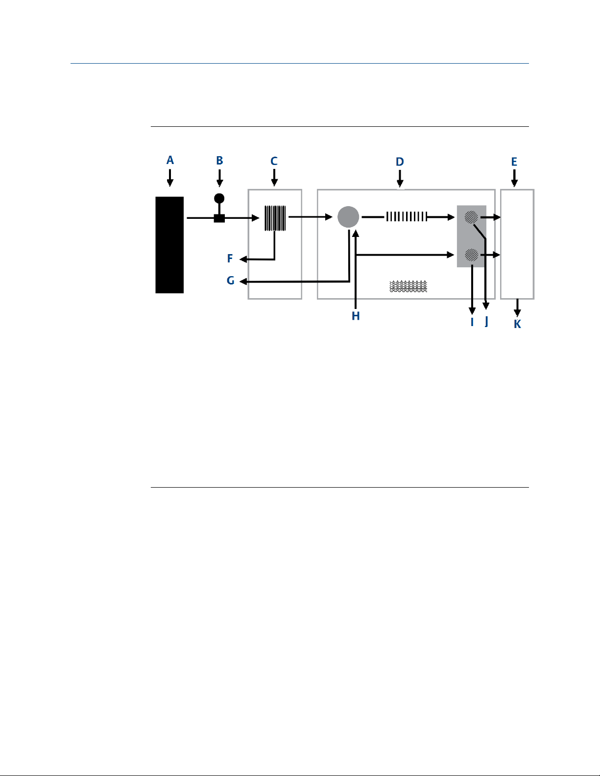
Figure 1-1: Gas chromatography process model
A. Process line
B. Probe
C. Sample system
D. Chromatograph oven
E. Gas chromatograph (GC) controller
F. Sample return
G. Slip stream
H. Carrier gas
I. Reference vent
J. Detector vent
K. Analysis results
Separation and analysis
The GC separates the sample gas into its components as follows:
1. A precise volume of sample gas is injected into one of the analytical columns. The
column contains a stationary phase (packing) that is either an active solid or an inert
solid support that is coated with a liquid phase (absorption partitioning).
2. A mobile phase (carrier gas) moves the sample gas through the column.
3. The selective retardation of the components takes place in the column, causing
each component to move through the column at a different rate. This separates the
sample into its constituent gases and vapors.
4. A detector located at the outlet of the analytical column senses the elution of
components from the column and produces electrical outputs proportional to the
concentration of each component.
Output from the electronic assembly is normally displayed on a remotely located personal
computer (PC) or in a distributed control system (flow computer).
Rosemount 700XA 11
Page 12

Overview Reference Manual
June 2022 2-3-9000-744
To connect the GC to a PC, use a direct serial line, an optional Ethernet cable, or a
Modbus®-compatible communication interface.
Several chromatograms may be displayed via Rosemount MON2020 with separate color
schemes, allowing you to compare present and past data.
In most cases, it is essential to use Rosemount MON2020 to configure and troubleshoot
the GC. The PC may be remotely connected via Ethernet, telephone, radio, or satellite
communications. Once installed and configured, the GC can operate independently for
long periods of time.
1.3 Software description
The gas chromatograph (GC) uses two distinct types of software. This enables total
flexibility in defining the calculation sequence, report content, format, type and amount of
data for viewing, control, and/or transmission to another computer or controller
assembly.
The two types are:
• Embedded GC firmware
1.3.1
• Rosemount MON2020 software
The RTOS firmware and the application configuration software are installed when the
Rosemount 700XA is shipped.
The application configuration is tailored to the customer’s process and shipped on a USB
stick. The hardware and software are tested together as a unit before the equipment
leaves the factory.
Rosemount MON2020 communicates with the GC and can be used to initiate site system
setup, such as operational parameters, application modifications, and maintenance.
Embedded gas chromatograph (GC) firmware
The GC’s embedded firmware supervises operation of the Rosemount 700XA through its
internal microprocessor-based controller.
All direct hardware interface is via this control software. It consists of a multitasking
program that controls separate tasks in system operation, as well as hardware self-testing,
user application downloading, start-up, and communication. After configuration, the GC
can operate as a stand-alone unit.
12 Emerson.com/Rosemount
Page 13

Reference Manual
2-3-9000-744 June 2022
Overview
1.3.2 Rosemount MON2020
The Rosemount MON2020 software provides the operator control of the gas
chromatograph (GC), monitors analysis results, and inspects and edits various parameters
that affect the analyzer operation. It also controls display and printout of the
chromatograms and reports, and it stops and starts automatic analysis cycling or
calibration runs.
After the equipment/software has been installed and the operation stabilized, automatic
operation takes place over an Ethernet network.
Rosemount MON2020 is a Windows™-based program that allows you to maintain,
operate, and troubleshoot a GC. Individual GC functions that can be initiated or controlled
by Rosemount MON2020 include, but are not limited to, the following:
• Valve activations
• Timing adjustments
• Stream sequences
• Calibrations
• Baseline runs
• Analyses
• Halt operation
• Stream/detector/heater assignments
• Stream/component table assignments
• Stream/calculation assignments
• Diagnostics
• Alarm and event processing
• Event sequence changes
• Component table adjustments
• Calculation adjustments
• Alarm parameters adjustments
• Analog scale adjustments
• Local operator interface (LOI) variable assignments (optional)
Reports and logs that can be produced, depending upon the GC application in use,
include, but are not limited to, the following:
• Configuration report
• Parameter list
• Analysis chromatogram
• Chromatogram comparison
• Alarm log (unacknowledged and active alarms)
Rosemount 700XA 13
Page 14

Overview Reference Manual
June 2022 2-3-9000-744
• Event log
• Various analysis reports
1.4 Theory of operation
Related information
Glossary
1.4.1 Thermal conductivity detector (TCD)
One of the detectors available on the gas chromatograph (GC) is a TCD, which consists of a
balanced bridge network with heat sensitive thermistors in each leg of the bridge. Each
thermistor is enclosed in a separate chamber of the detector block.
One thermistor is designated the reference element, and the other thermistor is
designated the measurement element. See Figure 1-2 for a schematic diagram of the TCD.
14 Emerson.com/Rosemount
Page 15
Reference Manual
Overview
2-3-9000-744 June 2022
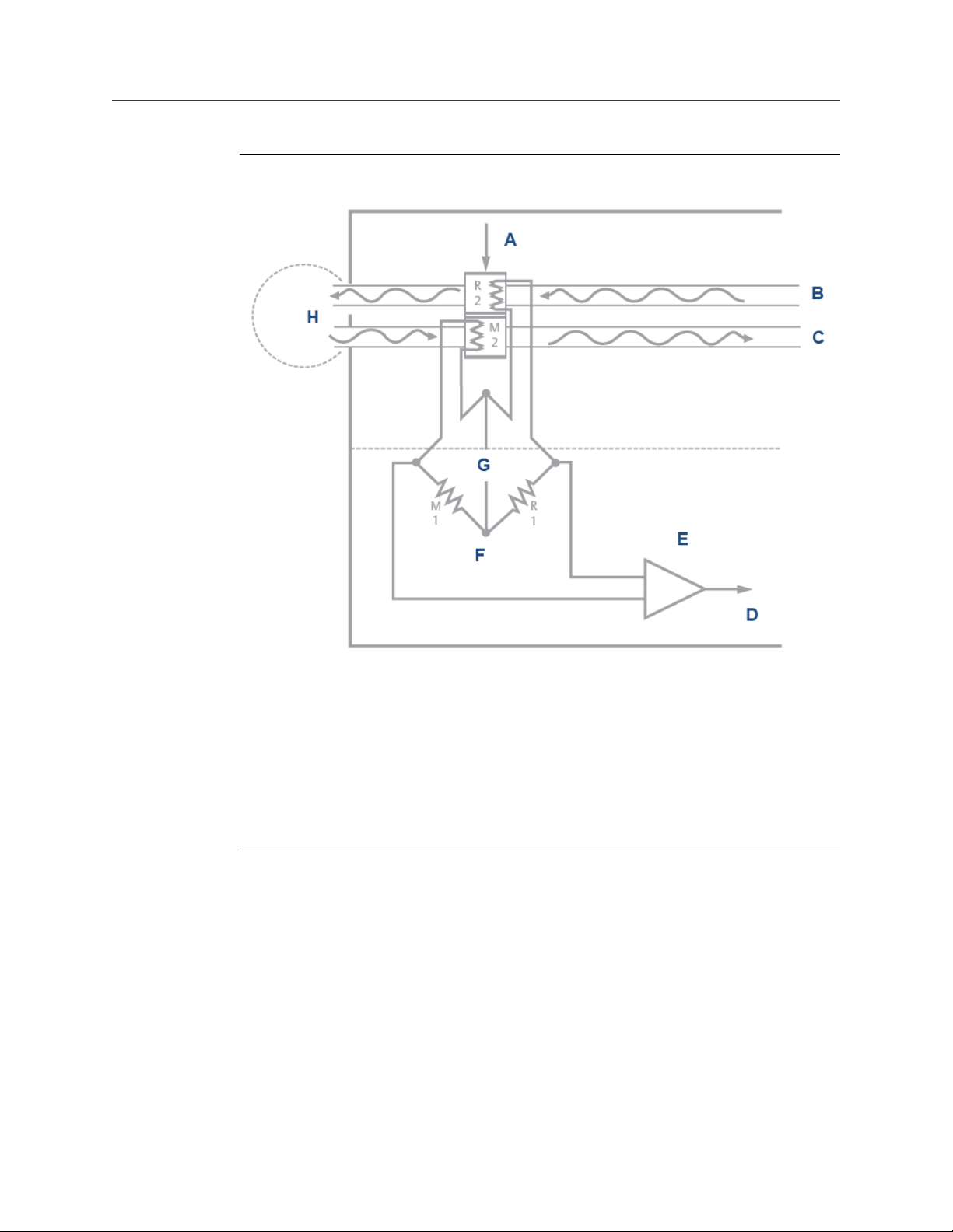
Figure 1-2: Analyzer assembly with TCD bridge
A. Detector block (in heated oven section of analyzer)
B. Reference flow (carrier gas)
C. Measurement flow ("MV")
D. Signal out
E. Preamplifier (in analyzer electronics housing)
F. Detector bridge
G. DC power
H. Valves, columns, etc.
In the quiescent condition, prior to injecting a sample, both legs of the bridge are exposed
to pure carrier gas. In this condition, the bridge is balanced, and the bridge output is
electrically nulled.
The analysis begins when the sample valve injects a fixed volume of sample into the
column. The continuous flow of carrier gas moves the sample through the column. As
successive components elute from the column, the temperature of the measurement
element changes.
The temperature change unbalances the bridge and produces an electrical output
proportional to the component concentration.
The differential signal developed between the two thermistors is amplified by the
preamplifier. Figure 1-3 illustrates the change in detector electrical output during elution
of a component.
Rosemount 700XA 15
Page 16
Overview Reference Manual
June 2022 2-3-9000-744
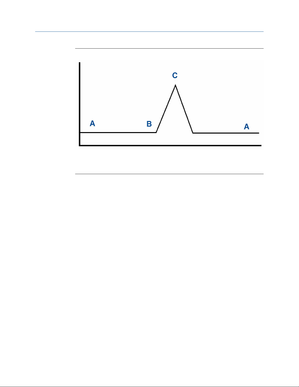
Figure 1-3: Detector output during component elution
A. Detector bridge balanced
B. Component begins to elute from column and is measured by thermistor.
C. Peak concentration of component
1.4.2
In addition to amplifying the differential signal developed between the two thermistors,
the preamplifier supplies drive current to the detector bridge.
The signal is proportional to the concentration of a component detected in the gas
sample. The preamplifier provides four different gain channels as well as compensation for
baseline drift.
The signals from the preamplifier are sent to the electronic assembly for component
concentration computation, recording, or viewing on a personal computer (PC) with
Rosemount MON2020.
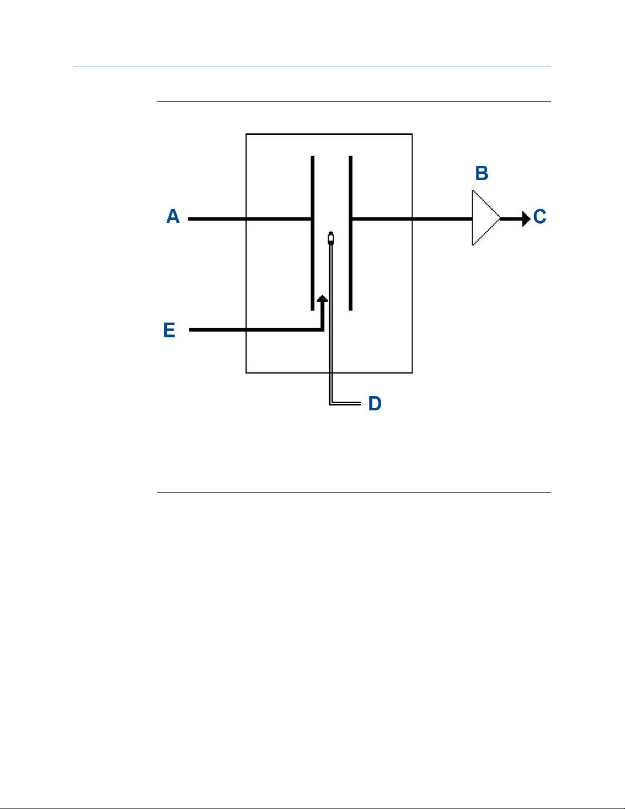
Flame ionization detector (FID)
Another detector available for the Rosemount 700XA is the flame ionization detector
(FID).
The FID requires a polarization voltage, and its output is connected to the input with a high
impedance amplifier that is called an electrometer. The burner uses a mixture of hydrogen
and air to maintain the flame. The sample of gas to be measured is also injected into the
burner. See Figure 1-4 for a schematic diagram of the FID.
16 Emerson.com/Rosemount
Page 17
Reference Manual
2-3-9000-744 June 2022
Figure 1-4: Analyzer assembly with FID detector bridge
Overview
1.4.3
A. Polarizing voltage
B. Electrometer
C. Signal out
D. Sample/hydrogen (H2)
E. Air
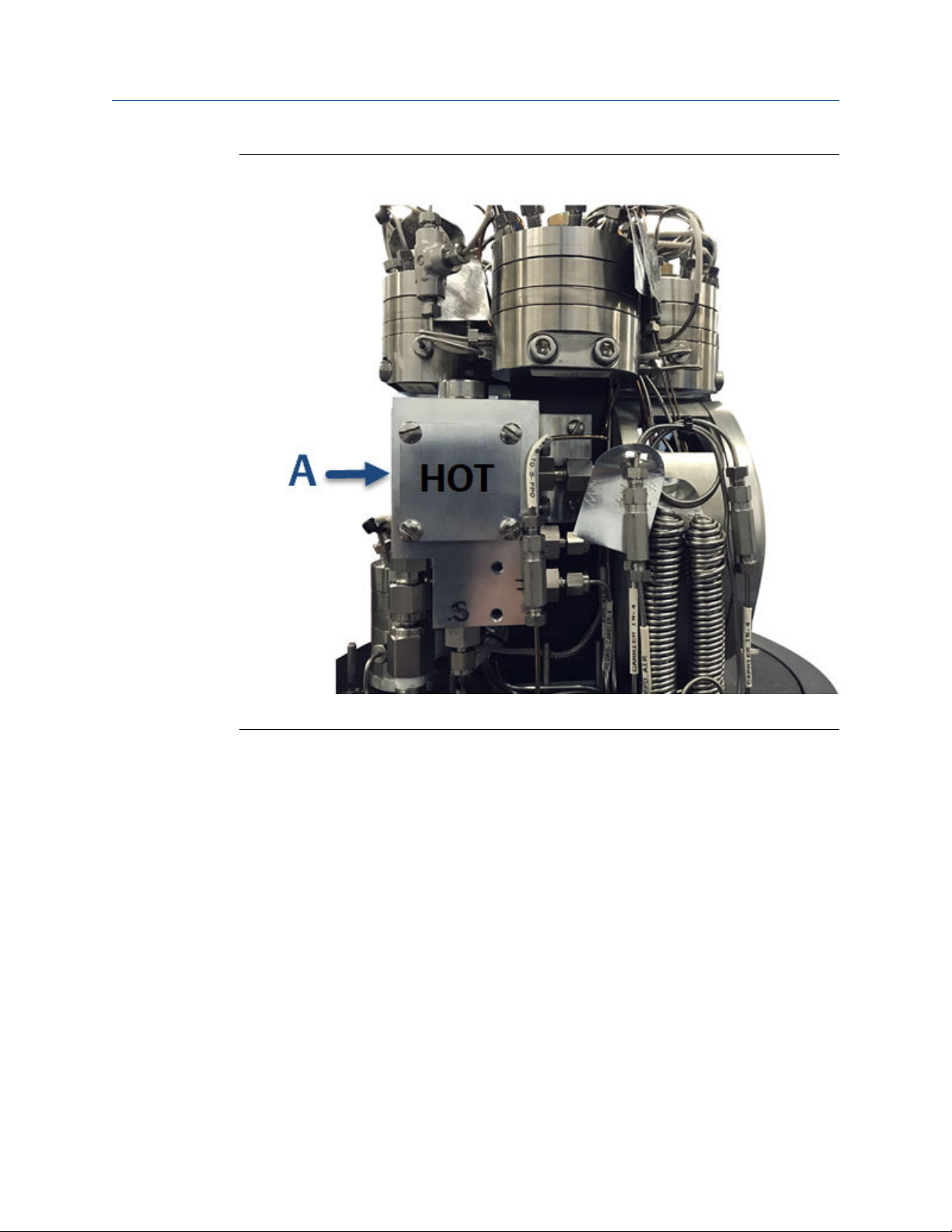
Micro flame photometric detector (µFPD) burner
The flame photometric detector (FPD) is a very sensitive and selective detector for the
analysis of sulfur or organophosphorus containing compounds. The detector is very stable
and easy to use.
As the analyte is burned in a hydrogen and air flame, a characteristic wavelength of light is
emitted at 394 nm for sulfur. The emitted light is amplified by the photomultiplier tube
(PMT) and processed by the signal processor. The response to phosphorus is linear and
quadratic to sulfur.
The Emerson µFPD solution consists of three key parts: burner, fiber cable, and PMT
electronics. The hydrogen and air in the burner help to burn the sample containing sulfur
components. The light emitted from the chemical reaction is then transmitted using the
fiber cable from the oven assembly to the electronics module. The PMT electronics
module consists of a 394 nm filter, a photomultiplier tube , and all the necessary
electronics to digitize the signal. The digital signal is then transmitted to the main central
processing unit (CPU) using CAN bus.
Rosemount 700XA 17
Page 18
Overview Reference Manual
June 2022 2-3-9000-744
Figure 1-5: µFPD burner - front view
A. µFPD burner
18 Emerson.com/Rosemount
Page 19

Reference Manual Overview
2-3-9000-744 June 2022
Figure 1-6: µFPD burner - back view
A. µFPD burner
B. Fiber cable
Rosemount 700XA 19
Page 20

Overview Reference Manual
June 2022 2-3-9000-744
Figure 1-7: µFPD burner - side view
A. µFPD burner and cable
20 Emerson.com/Rosemount
Page 21

Reference Manual Overview
2-3-9000-744 June 2022
Figure 1-8: µFPD PMT
A. µFPD PMT in the upper enclosure
1.4.4
The detection system in the µFPD uses the reactions of sulfur components in a
hydrogen/air flame as a source for analytical detection. The source of the µFPD's signal is
derived from the light produced by an excited molecule created in the flame's
combustion, that is, a photochemical process called chemiluminescence. A thermocouple
is fitted to the flame cell to ensure that the flame is present. If the flame is not detected,
the electrometer shuts off the hydrogen to the flame cell. It then supplies a voltage to the
igniter, waits five seconds, and opens the hydrogen shut off valve. The electrometer will
make between one and five ignition attempts if necessary. You can select the number of
ignition attempts on the Hardware → Detector screen. If the electrometer does not
succeed in igniting, then the GC shuts off the hydrogen, triggers an alarm, and waits for
attention from the operator.
Related information
Micro flame photometric detector (µFPD)
Micro flame photometric detector (µFPD) electronics
module
The electronics module contains two chambers. The internal chamber contains the photo
multiplier tube (PMT) to insulate it from outside temperature changes. The external
chamber is a thermo-electric cooler (TEC) controlled chamber, which houses the internal
chamber along with the electronic board that generates high voltage power through the
PMT.
Rosemount 700XA 21
Page 22

Overview Reference Manual
June 2022 2-3-9000-744
Figure 1-9: Electronics module, exploded view
A. Apply thermal compound to both sides.
22 Emerson.com/Rosemount
Page 23

Reference Manual Overview
2-3-9000-744 June 2022
Figure 1-10: Electronics module, detailed
A. Maier photonics filter
B. O-ring
On the outside of the external chamber is the electronics main board. This board is the
vital part of the µFPD electronics module. It controls the temperature of the TEC, provides
power to the igniter, monitors the flame temperature, and digitizes the PMT signal and
transmits to the main central processing unit (CPU) using CAN bus.
Rosemount 700XA 23
Page 24

Overview
June 2022 2-3-9000-744
Reference Manual
1.4.5 Liquid sample injection valve (LSIV)
The optional LSIV converts a liquid sample into a gas sample for analysis.
Figure 1-11: LSIV cross section
A. Liquid sample
B. Air supply: four-way action
C. Thermal barrier adapter flange: polyether ether ketone (PEEK)
D. O-ring
E. Heater element
Figure 1-12: LSIV
The LSIV penetrates the wall of the lower compartment and is held in place by a retaining
ring.
24 Emerson.com/Rosemount
Page 25

Reference Manual
2-3-9000-744 June 2022
The mounting arrangement is designed to ensure integrity of the flameproof enclosure.
The flash chamber block is stainless steel and is surrounded by an insulating mounting
adapter. It houses the heater and a resistance temperature detector (RTD).
The next section houses sample input connections and stem sealing components. There
are two ⅛-in O.D. tubing ports in this section; one port is for sample input, the other is the
exhaust for sample flow.
The flash chamber components are within the enclosure cavity and surrounded with
insulating covers. At working temperatures, the surfaces of these covers become very hot
to the touch.
The tip of the cylindrical flash chamber is the port where the flashed sample is taken to the
oven system. The port near the outer diameter of the end of the heated flash chamber
block is the input for carrier gas.
Overview
1.4.6
1.4.7
Methanator
After all other components have been separated from the sample, carbon monoxide and
carbon dioxide, which are normally present in quantities too small to be detected by the
gas chromatograph (GC), can be sent through the optional methanator, where the two
gases are combined with hydrogen to make methane in a heat-generated catalytic
reaction.
The methanator is also known as a methanizer or catalytic converter.
Data acquisition
Every second, the controller assembly takes exactly 50 equally spaced data samples (i.e.,
one data sample every 20 milliseconds).
As a part of the data acquisition process, groups of incoming data samples are averaged
together before the result is stored for processing. Non-overlapping groups of 50 samples
are averaged and stored, and thus reduce the effective incoming data rate to 50/10
samples per second. For example, if N = 5, then a total of 40/5 or 8 (averaged) data
samples are stored every second.
The value for the variable N is determined by the selection of a peak width parameter
(PW). The relationship is
N = PW
where PW is given in seconds. Allowable values of N are 1 to 63; this range corresponds to
PW values of 2 to 63 seconds.
The variable N is known as the integration factor. This term is used because N determines
how many points are averaged, or integrated, to form a single value. The integration of
data upon input, before storing, serves two purposes:
• The statistical noise on the input signal is reduced by the square root of N. In the case of
N = 4, a noise reduction of 2 would be realized.
• The integration factor controls the bandwidth of the chromatograph signal. It is
necessary to match the bandwidth of the input signal to that of the analysis algorithms
in the controller assembly. This prevents small, short-duration perturbations from
Rosemount 700XA 25
Page 26

Overview
June 2022 2-3-9000-744
being recognized as true peaks by the program. It is therefore important to choose a
peak width that corresponds to the narrowest peak in the group under consideration.
Reference Manual
1.4.8 Peak detection
For normal area or peak height concentration evaluation, the determination of a peak's
start point and end point is automatic.
The manual determination of start and end points is used only for area calculations in
Forced Integration mode. Automatic determination of peak onset or start is initiated
whenever Integrate Inhibit is turned off. Analysis is started in a region of signal quiescence
and stability, such that the signal level and activity can be considered as baseline values.
Note
The controller assembly software assumes that a region of signal quiescence and stability
will exist.
Having initiated a peak search by turning Integrate Inhibit off, the controller assembly
performs a point by point examination of the signal slope. This is achieved by using a
digital slope detection filter, a combination low pass filter and differentiator. The output is
continually compared to a user-defined system constant called Slope Sensitivity. A default
value of 8 is assumed if no entry is made. Lower values make peak onset detection more
sensitive, and higher values make detection less sensitive. Higher values (20 to 100) would
be appropriate for noisy signals, (e.g., high amplifier gain).
Onset is defined where the detector output exceeds the baseline constant, but peak
termination is defined where the detector output is less than the same constant.
Sequences of fused peaks are also automatically handled. This is done by testing each
termination point to see if the region immediately following it satisfies the criteria of a
baseline. A baseline region must have a slope detector value less than the magnitude of
the baseline constant for a number of sequential points. When a baseline region is found,
this terminates a sequence of peaks.
A zero reference line for peak height and area determination is established by extending a
line from the point of the onset of the peak sequence to the point of the termination. The
values of these two points are found by averaging the four integrated points just prior to
the onset point and just after the termination points, respectively.
The zero reference line will, in general, be non-horizontal, and thus compensates for any
linear drift in the system from the time the peak sequence starts until it ends.
In a single peak situation, peak area is the area of the component peak between the curve
and the zero reference line. The peak height is the distance from the zero reference line to
the maximum point on the component curve. The value and location of the maximum
point is determined from quadratic interpolation through the three highest points at the
peak of the discrete value curve stored in the controller assembly.
For fused peak sequences, this interpolation technique is used both for peaks, as well as
valleys (minimum points). In the latter case, lines are dropped from the interpolated valley
points to the zero reference line to partition the fused peak areas into individual peaks.
The use of quadratic interpolation improves both area and height calculation accuracy and
eliminates the effects of variations in the integration factor on these calculations.
26 Emerson.com/Rosemount
Page 27

Reference Manual Overview
2-3-9000-744 June 2022
For calibration, the controller assembly may average several analyses of the calibration
stream.
1.4.9 Basic analysis computations
Two basic analysis algorithms are included in the controller assembly:
Area analysis
Peak height analysis
Calculates area under component peak.
Measures height of component peak.
NOTICE
Consult the Rosemount MON2020 Software for Gas Chromatographs Reference Manual
for more information.
Concentration analysis - response factor
Concentration calculations require a unique response factor for each component in an
analysis. These response factors may be manually entered by an operator or determined
automatically by the system through calibration procedures (with a calibration gas
mixture that has known concentrations).
The response factor calculation, using the external standard, is:
where
ARF
Area
Cal
Ht
HRF
Area response factor for component n in area per mole percent
n
Area associated with component n in calibration gas
n
Amount of component n in mole percent in calibration gas
n
Peak height associated with component n mole percent in calibration gas
n
Peak height response factor for component n
n
The controller assembly stores calculated response factors to use in the concentration
calculations; these response factors are printed out in the configuration and calibration
reports.
Average response factor is calculated as follows:
where
RFAVG
Rosemount 700XA 27
Area or height average response factor for component n
n
Page 28

Overview
June 2022 2-3-9000-744
Reference Manual
RF
k
The percent deviation of new RF averages from old RF average is calculated in the following
manner:
where the absolute value of percent deviation has been previously entered by the
operator.
Area or height average response factor for component n from the calibration
i
run
Number of calibration runs used to calculate the response factors
Concentration calculation - mole percentage (without
normalization)
After response factors have been determined by the controller assembly or entered by the
operator, component concentrations are determined for each analysis by using the
following equations:
where:
ARF
Area
CONC
Ht
HRF
Component concentrations may also be input through analog inputs 1 to 4 or may be
fixed. If a fixed value is used, the calibration for that component is the mole percent that
will be used for all analyses.
Area response factor for component n in area per mole percent
n
Area associated with component n in unknown sample
n
Concentration of component n in mole percent
n
Peak height associated with component n mole percent in unknown sample
n
Peak height response factor for component n
n
Concentration calculation in mole percentage (with
normalization)
The normalized concentration calculation is:
where:
28 Emerson.com/Rosemount
Page 29

Reference Manual Overview
2-3-9000-744 June 2022
CONCN
Normalized concentration of component n in percent of total gas
n
concentration
CONC
Non-normalized concentration of component n in mole percent for each k
i
component
CONC
k
Non-normalized concentration of component n in mole percent
n
Number of components to be included in the normalization
Note
The average concentration of each component will also be calculated when data
averaging is requested.
Rosemount 700XA 29
Page 30

Overview Reference Manual
June 2022 2-3-9000-744
30 Emerson.com/Rosemount
Page 31
Reference Manual Equipment description and specifications
2-3-9000-744 June 2022
2 Equipment description and
specifications
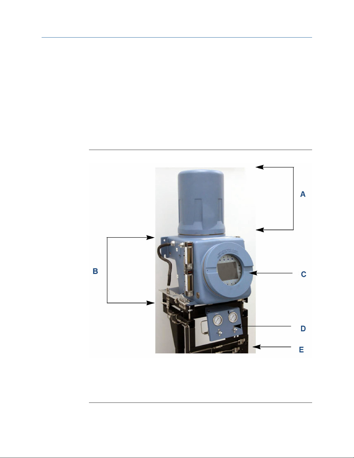
2.1 Equipment description
The Rosemount 700XA consists of a copper-free aluminum explosion-proof chamber and
a front panel assembly. The chamber is divided into two compartments that together
house the gas chromatograph's (GC's) major components. This GC is designed for
hazardous locations.
Figure 2-1: Rosemount 700XA Gas Chromatograph
A. Upper compartment
B. Lower compartment
C. Front panel assembly
D. Mechanical regulators
E. Sampling system (optional)
Rosemount 700XA 31
Page 32
Equipment description and specifications Reference Manual
June 2022 2-3-9000-744
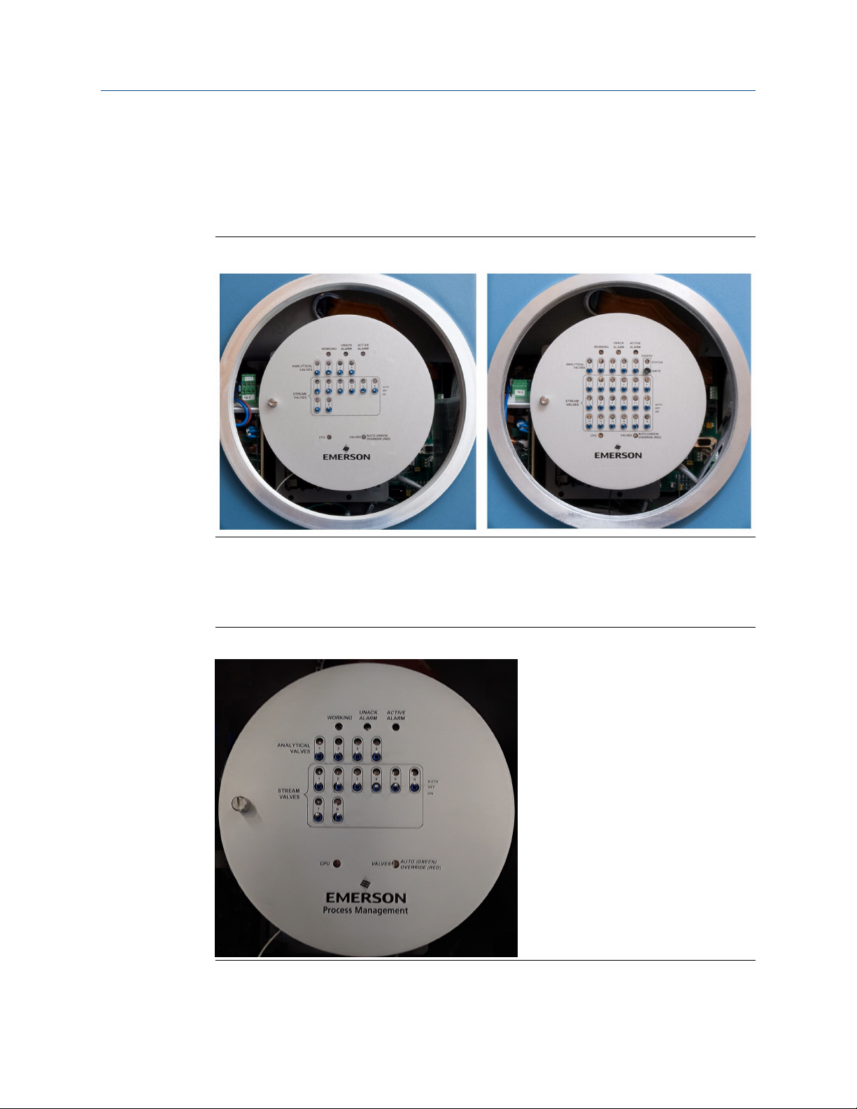
2.1.1 Front panel assembly
The front panel assembly is located on the front section of the lower enclosure and
consists of a removable, explosion-proof panel that shields either a switch panel or a local
operator interface (LOI).
Figure 2-2: 8-stream switch panel (left) and 18-stream switch panel (right)
Switch panel
The switch panel contains a network of On/Off switches that allow the operator to
manually control the gas chromatograph's (GC's) stream and analytical valves.
Figure 2-3: Eight stream switch panel
32 Emerson.com/Rosemount
Page 33

Reference Manual Equipment description and specifications
2-3-9000-744 June 2022
There are two types of switch panels: 8-stream and 18-stream. The 8-stream switch panel
is the standard panel, and is used when the GC has only one heater/solenoid board
installed; if two heater/solenoid boards are installed, then the 18-stream switch panel is
used.
Figure 2-4: Stream valve switches
A valve has the following three operational modes:
AUTO
The valve turns on and off according to the Timed Events table (accessible through
Rosemount MON2020). To set a valve to AUTO mode, set its switch on the switch
panel to the Up position.
OFF
The valve turns off and remains off until the operational mode is changed. To set a
valve to OFF mode, set its switch on the switch panel to the center position (the
switch is neither flipped up nor down).
ON
The valve turns on and remains on until the operational mode is changed. To set a
valve to ON mode, set its switch on th switch panel to the down position.
Figure 2-5: Status LEDs
Top of switch panel
The switch panels also contain the following status lights that allow you to monitor the
GC’s condition:
Working
Unack. Alarm
Turns green when the GC is in Analysis mode.
Turns yellow if there is an unacknowledged alarm.
Active Alarm
Flame
ionization
detector (FID)/
flame
photometric
detector (FPD)
Rosemount 700XA 33
Turns red if there is an active alarm.
The 18-stream switch panel contains an FID or FPD status LED that can
indicate the following:
• A green light means the flame has ignited.
• A flashing yellow light means an attempt is being made to ignite
the flame.
Page 34

Equipment description and specifications Reference Manual
June 2022 2-3-9000-744
• A red light means the flame as gone out or that the FID or FPD is
over-temperature.
Figure 2-6: FID/FPD status LED
Figure 2-7: Status LEDs (bottom of switch panel)
Rosemount MON2020 detects the FID and FPD statuses. The operator can ignite the flame
remotely using Rosemount MON2020 or manually light the flame.
Figure 2-8: Rosemount MON2020 status indicators
Note
During GC start up, all LEDs turn on for approximately ten seconds.
34 Emerson.com/Rosemount
Page 35

Reference Manual Equipment description and specifications
2-3-9000-744 June 2022
Local operator interface (LOI)
The optional LOI gives you in-depth control over the functions of the gas chromatograph
(GC).
The LOI has a high resolution color display that is touch key activated and allows you to
operate the GC without a computer.
Figure 2-9: LOI
The LOI includes the following features:
• Color LCD display with VGA (640 x 480 pixels) resolution
• ASCII text and graphics modes
• Adjustable auto-backlighting
• Eight infrared-activated touch screen keys that eliminate the requirement for a
magnetic pen
• Complete GC status, control, and diagnostics, including full chromatogram display
Rosemount 700XA 35
Page 36

Equipment description and specifications Reference Manual
June 2022 2-3-9000-744
2.1.2 Upper compartment
The upper compartment contains the following components:
Valves
Column module
Thermal conductivity
detector (TCD)
Two heating
elements
One temperature
switch for each
heating element
Pressure switch
Flame ionization
detector (FID)
Flame photometric
detector (FPD)
There are two types of XA valves: 6-port and 10-port. A gas
chromatograph (GC) can have a maximum of six XA valves
consisting of a maximum of four 10-port valves.
Either capillary or micro-packed.
The GC has a maximum of two TCDs as well as a micro flame
photometric detector (µFPD), or a flame ionization detector
(FID).
A top hat heater and a column heater.
The switch turns off its heating element if the heating element
reaches 320 °F (160 °C).
The pressure switch activates when the carrier pressure falls
below a predetermined set point. When activated, the switch
triggers a general alarm that displays on the front panel or local
operator interface (LOI) and in Rosemount MON2020.
The optional FID detects trace levels of hydrocarbons.
The optional FPD, which detects trace levels of sulfur
compounds, can be used in place of a TCD, installed as a side car
component. For more information, refer to the
FPD for Gas Chromatographs Hardware Reference Manual.
Micro flame
photometric
detector (µFPD)
Methanator
Liquid sample
injection valve (LSIV)
Related information
Micro flame photometric detector (µFPD)
36 Emerson.com/Rosemount
The optional integral µFPD detects trace levels of sulfur
compounds.
The methanator, or catalytic converter, is an optional
component that converts otherwise undetectable carbon
dioxide and/or carbon monoxide into methane by adding
hydrogen and heat to the sample.
The optional LSIV can vaporize a liquid sample, thereby
expanding the GC’s capability to measure liquids.
Page 37

Reference Manual Equipment description and specifications
2-3-9000-744 June 2022
2.1.3 Lower compartment
The lower compartment consists of the following components:
Backplane
Card cage
The backplane is the gas chromatograph's (GC's) central printed circuit
board (PCB). Its main function is as a connection point for the GC's
specialized plug-in PCBs. The backplane also hosts connections for analog
outputs and analog inputs, serial ports, and an Ethernet port.
WARNING
Explosion
Failure to de-energize the analyzer may cause an explosion and severely
injure personnel.
Before opening the analyzer, disconnect all electrical power and
ensure that the area is free of explosive gases.
Keep cover tight while circuits are live.
Use cables or wires suitable for the marked "T" ratings.
Cover joints must be cleaned before replacing the cover.
Conduit runs to the enclosure must have sealing fitting adjacent to
enclosure.
The card cage holds the specialized PCBs that plug into the backplane. The
following PCBs are housed in the card cage:
• Preamplifier board
• Central processing unit (CPU) board
Optional
AC/DC
power
supply
• Base in/out (I/O) board
• Heater/solenoid board
The card cage also has four additional slots for the following optional
PCBs:
• A second preamplifier board
• A second heater/solenoid board
• Two optional communications boards
WARNING
Electric shock
Failure to check the power supply label may result in injury or death to
personnel or cause damage to the equipment. Applying 110 to 220 Vac
to a DC power input GC severely damages the GC.
See power supply label prior to connection.
Check the GC's power design to determine if it is equipped for AC or
DC power.
Rosemount 700XA 37
Page 38

Equipment description and specifications Reference Manual
June 2022 2-3-9000-744
Note
The Rosemount 700XA CSA-certified unit is equipped with ¾-in NPT
adapters.
2.1.4 Mechanical pressure regulators
The mechanical pressure regulators and gauges are used to set and monitor the pressure
of the carrier gas flow through the gas chromatograph's columns, as well as the pressure
of the flame ionization detector (FID) or flame photometric detector (FPD) air and fuel
(H2), if installed.
The regulators and gauges are typically located on front of the analyzer below the
electronics enclosure.
Figure 2-10: Regulators and gauges
38 Emerson.com/Rosemount
Page 39
Reference Manual Equipment description and specifications
2-3-9000-744 June 2022
2.2 Specifications
Type Specification
Dimensions (without sampling
system)
Weight (without sampling system) Approximately 150 lb (68.0 kg)
Mounting • Wall mount (standard)
Power usage 125 to 250 W
Valve actuation • Sample gas: 90 psig (6 barg) maximum
Environment
Indoor/outdoor
Hazardous area certifications
(hardware dependent)
Height x width x depth: 50 in (1,270 mm) x 40 in (1,016 mm) x 24 in (610 mm)
• Free-standing (optional)
• Carrier gas: 90 psig (6 barg) maximum
• Actuation gas: 110 psig (8 barg) maximum
Thermal conductivity detector (TCD): -4 °F (-20 °C) to 140 °F (60 °C)
Flame ionization detector (FID): 32 °F (0 °C) to 140 °F (60 °C)
Flame photometric detector (FPD): 32 °F (0 °C) to 122 °F (50 °C)
USA and Canada
• Class I, Zone 1, Ex/AEx db IIC, Gb T6/T4/T3
• Class I, Division 1, Groups B, C, and D, IP66
EU ATEX and IECEx
• Ex db IIC Gb T6/T4/T3
• Ta = -4 °F (-20 °C) to 140 °F (60 °C)
• SIRA 08ATEX 1328X
• IECEx SIR 08.0093X
Consult factory for additional product certifications available.
Table 2-1: Approval temperature ratings
T6 Basic system; no alternative options included
T4 Liquid sample injection valve (LSIV) option included
T4 Heat trace option with a maximum 176 °F (80 °C) temperature switch set point
T3 Heat trace option with a maximum 230 °F (110 °C) temperature switch set point
Rosemount 700XA 39
Page 40

Equipment description and specifications Reference Manual
June 2022 2-3-9000-744
2.2.1 Electronics hardware
Type Specifications
Communication (standard) • Analog inputs:
— Two standard 4-20 mA inputs filtered with transient protection
• Analog outputs:
— Six isolated outputs, 4–20 mA
• Serial communication ports:
— Three termination blocks
— Configurable as RS-232, RS-422, or RS-485
— One D-sub (9-pin) port for personal computer (PC) connection
• Digital inputs:
— Five inputs, user assignable
— Optically isolated, rated to 30 Vdc at 0.5 A
• Digital outputs:
— Five outputs, user assignable
— Form C and electro-mechanically isolated, 24 Vdc
Communication (optional)
Ethernet Two available connections
Four expansion slots available for additional communications. Each slot has the
capacity to add one of the following:
• Four analog inputs (isolated) card
• Four analog outputs (isolated) card
• Eight digital inputs (isolated) card
• Five digital outputs (isolated) card
• One RS-232, RS-422, or RS-485 serial connection card (up to two maximum)
• One RJ45 port
• One 4-wire termination – with 10/100 Mbps
40 Emerson.com/Rosemount
Page 41
Reference Manual Equipment description and specifications
2-3-9000-744 June 2022
2.2.2 Airless analytical oven
Type Specification
Valves 6-port and 10-port XA valves; piston-operated diaphragms with pneumatic
actuation
Columns Maximum of 90 ft (27 m) of micro-packed columns; 1/16-in outside diameter
or
300 ft (91 m) of capillary columns
Solenoid actuation • 24 Vdc
• Maximum 100 psig (7 barg)
Temperature control • 24 Vdc
• 2 heaters
• 2 optional heaters
• Maximum oven operating temperature of 302 °F (150 °C)
2.2.3 Software
Type Specification
Software Windows™-based Rosemount MON2020
Firmware Embedded firmware
Methods 8 Timed Event tables and 8 Component Data tables
Analysis clocks Multiple analysis clock configurations
Peak Integration • Fixed time or auto slope and peak identification
• Update retention time upon calibration or during analysis
Cyber security Encrypted SSL communication between gas chromatograph (GC) and Rosemount
MON2020
2.2.4 Corrosion protection
Type Specification
Enclosure material Copper-free and aluminum-coated with industrial grade powder coat suitable for
high humidity and salt-laden environments.
Process wetted materials Stainless steel; if the function of an item excludes the use of stainless steel, such as
the glass rotameter tubes, materials that are resistant to corrosion are used.
Electronics All electronic circuit boards are covered with a clear conformal coating.
Rosemount 700XA 41
Page 42

Equipment description and specifications Reference Manual
June 2022 2-3-9000-744
2.2.5 Archived data storage capabilities
Type of record Number of records Remarks
Analysis results 31,744 88 days with 4-minute cycle time
Final calibration results 370 1 year
Calibration results 100 N/A
Final validation results 370 1 year
Validation results 100 N/A
250
(1)
(1)
Approximately 22.5 days assuming running 4minute analysis and 1 analysis clock
(2)
(2)
Approximately 9 days, assuming 4-minute
cycle time
Analysis chromatograms 8,515
Final calibration chromatograms 370 1 year
Final validation chromatograms 370 1 year
Protected chromatograms 100 User-selectable
Hourly averages
(3)
Daily averages 365 1 year
Weekly averages 58 1 year
Monthly averages 12 1 year
Variable averages 250
Every run (up to 250 variables) 250
(1)
(1)
N/A
N/A
Alarm logs 1000 N/A
Event logs 1000 N/A
(1) Changed from 2.0.x release.
(2) The gas chromatograph (GC) can store final calibration and validation chromatograms for a year, provided that no
more than one calibration/validation is run per day and the cycle time is less than 15 minutes. If the cycle time exceeds
15 minutes, the oldest final calibration/validation chromatograms are deleted to make room for newer ones.
(3) You can have a total of 256 averages, including hourly, 24-hour, weekly, monthly, variable, and every run averages.
42 Emerson.com/Rosemount
Page 43

Reference Manual Getting started
2-3-9000-744 June 2022
3 Getting started
Emerson started and inspected your gas chromatograph (GC) before it left the factory.
Emerson also installed program parameters and documented them in the GC Config
Report furnished with your GC.
3.1 Select site
The site you select for the gas chromatograph (GC) is important for measurement
accuracy.
Procedure
Install the GC as close as possible to the sample system, but allow for adequate access
space for maintenance tasks and adjustments.
WARNING
Hazardous area explosion hazard
Failure to follow this warning may result in injury or death to personnel.
Do not use a personal computer (PC) or printer in a hazardous area.
Emerson provides serial and Ethernet communication links to connect the analyzer to
the PC and to connect to other computers and printers in a safe area.
Allow a minimum of 3 ft (0.91 m) in front of the GC for operator access. Ensure that
exposure to radio frequency interference (RFI) is minimal.
3.2 Unpack the gas chromatograph (GC)
Unpack and inspect the Rosemount 700XA upon receipt.
WARNING
This device is heavy equipment. Two people are required to move the device.
Failure to observe this warning may cause serious injury to personnel.
Observe all proper lifting methods as defined by your site operating procedures.
Procedure
1. Unpack the equipment.
a) Remove the GC from the shipping crate.
b) Remove the USB memory stick containing the software, applications, Quick
Start Guide, and manuals.
Rosemount 700XA 43
Page 44

Getting started Reference Manual
June 2022 2-3-9000-744
Note
The Rosemount MON2020 version number is located on the back of the USB
card.
2. Retain the shipping information.
3. Inspect all parts and assemblies for possible shipping damage.
4. If any parts or assemblies appear to have been damaged in shipment, first file a
claim with the carrier.
5. Next, complete a full report describing the nature and extent of the damage and
forward this report immediately to your Emerson Customer Care representative.
Include the GC's model number in the report.
Emerson will provide disposition instructions as soon as possible. If you have any
questions regarding the claim process, contact your Emerson Customer Care
representative for assistance.
6. Only proceed to install and start up the GC if all required materials are on hand and
free from obvious defects.
7. If your GC is configured with an flame ionization detector (FID) or flame
photometric detector (FPD), remove the vent plug from the FID/FPD outlet.
NOTICE
The vent plug has a tag attached to it that reads: REMOVE VENT PLUGS PRIOR TO
OPERATION. Failure to remove the cap could result in a performance failure or
damage to the detector.
44 Emerson.com/Rosemount
Page 45

Reference Manual Getting started
2-3-9000-744 June 2022
3.3 Required tools and components
You will need the following tools and components to install the gas chromatograph (GC).
• Zero grade carrier gas:
— 99.995% pure
— Less than 5 ppm water
— Less than 0.5 ppm hydrocarbons
• High pressure dual-stage regulator for the carrier gas cylinder
— High side up to 3,000 psig (207 barg)
— Gauge (psig)
— Low side capable of controlling pressure up to 150 psig (10 barg)
• Calibration standard gas with correct number of components and concentrations
• Dual-stage regulator for the calibration gas cylinder with a low pressure side capable of
controlling pressure up to 30 psig (2.07 barg)
• Sample probe regulator (fixture for procuring the stream or sample gas for
chromatographic analysis)
• Coalescing filter
• Membrane filter
• ⅛-in stainless steel tubing
— For connecting calibration gas to the GC
— For connecting carrier gas to the GC
— For connecting stream gas to the GC
— Sulfinert tubing required if sulfur components are present in calibration gas
• Heat tracing, as required for sample transport and calibration lines
• Miscellaneous tube fittings, tubing benders, and tubing cutter
• 14 American wire gauge (AWG) (18 metric wire gauge [MWG]) or larger electrical
wiring and conduit to provide 120 or 240 Vac, single phase, 50 to 60 Hz, from an
appropriate circuit breaker and power disconnect switch.
• Digital volt-ohm meter with probe-type leads
• Flow measuring device
• Open-end wrenches sized ¼-in, 5/16-in, 7/16-in, ½-in, 9/16-in, and ⅝-in.
• Torque wrench
Related information
Gas chromatograph wiring
Rosemount 700XA 45
Page 46

Getting started Reference Manual
June 2022 2-3-9000-744
3.4 Supporting tools and components
WARNING
Hazardous area explosion hazard
Failure to follow this warning may result in injury or death to personnel.
Do not use a personal computer (PC) or printer in a hazardous area.
Emerson provides serial and Ethernet communication links to connect the analyzer to
the PC and to connect to other computers and printers in a safe area.
• Use a Windows®-based PC and either a direct or remote communications connection
to interface with the GC.
NOTICE
Consult the Rosemount MON2020 Software for Gas Chromatographs Reference
Manual for more information.
• The GC comes with an Ethernet port on the backplane factory-wired with an RJ-45
connector.
Related information
Connect directly to a personal computer (PC) using the gas chromatograph's (GC’s)
Ethernet1 port
46 Emerson.com/Rosemount
Page 47

Reference Manual Installation and start-up
2-3-9000-744 June 2022
4 Installation and start-up
Note
Because the Rosemount 700XA is available in different configurations, it is possible that
not all of the instructions in this section apply to your particular gas chromatograph (GC).
In most cases, however, to install and set up a Rosemount 700XA, Emerson recommends
that you follow the instructions in the same order as they are presented in this manual.
4.1 Installation considerations
Before installing the gas chromatograph (GC):
1.
WARNING
The GC is heavy and has a high potential of injuring personnel or damaging
equipment.
Anchor the GC solidly before making electrical connections.
Until all bolts are tight, ensure that the GC is supported to prevent unforeseen
accidents.
2. Ensure that the connections to the enclosure meet local standards.
3. Use approved seals: either cable glands or conduit seals.
a. Install conduit seals within 3 in (76 mm) of the enclosure.
b. Seal unused openings with approved blanks (plugs). Threads for these
openings are M32 x 1.5.
4. Remove any packing materials before powering up the GC.
5.
6.
WARNING
Hazardous area explosion hazard
Failure to follow this warning may result in injury or death to personnel.
Do not use a personal computer (PC) or printer in a hazardous area.
Emerson provides serial and Ethernet communication links to connect the
analyzer to the PC and to connect to other computers and printers in a safe area.
Related information
Mounting arrangements
4.2
Rosemount 700XA 47
Mounting arrangements
The Rosemount 700XA can be installed in one of the following mounting arrangements:
Page 48

Installation and start-up Reference Manual
June 2022 2-3-9000-744
• Wall mount
• Pole mount
• Floor mount
WARNING
This device is heavy equipment. Two people are required to move the device.
Failure to observe this warning may cause serious injury to personnel.
Observe all proper lifting methods as defined by your site operating procedures.
4.2.1 Mount the gas chromatograph (GC) to the wall
The simplest mounting arrangement is the wall mount.
If you specify Wall Mount on the sales order, Emerson will ship the GC with a wall mount
installation kit. Four locations on the mounting ears are available for support.
WARNING
The GC is heavy and has a high potential of injuring personnel or damaging equipment.
Anchor the GC solidly before making electrical connections.
Until all bolts are tight, ensure that the GC is supported to prevent unforeseen
accidents.
Figure 4-1: Wall mount
48 Emerson.com/Rosemount
Page 49

Reference Manual Installation and start-up
2-3-9000-744 June 2022
Prerequisites
Pre-install a pair of 7/16-in diameter bolts with washers on the wall before installing the
final pair of bolts.
The first pair of bolts should be approximately 41.63 in (1,057 mm) off the ground, and
13.63 in (346 mm) apart. Each bolt should have 0.63 in (16 mm) of bare length projecting.
Drill a second pair of holes 3.56 in (90.4 mm) above the first.
Procedure
1. Maneuver the GC so that the notches in the mounting ears can be placed over the
bolts on the wall and then place the washers over the bolts.
2. Install the second pair of bolts with washers and then tighten all the bolts.
4.2.2
Mount the gas chromatograph (GC) to a pole
The pole mount arrangement uses an additional plate and spacers to allow the necessary
clearance for nuts.
If you specify Pole Mount on the sales order, Emerson will provide the necessary hardware.
WARNING
The GC is heavy and has a high potential of injuring personnel or damaging equipment.
Anchor the GC solidly before making electrical connections.
Until all bolts are tight, ensure that the GC is supported to prevent unforeseen
accidents.
Figure 4-2: Pole mount
Procedure
1. Use the U-bolt to firmly install the large plate on the pole about 44 in (1,118 mm)
above the ground.
Rosemount 700XA 49
Page 50

Installation and start-up Reference Manual
June 2022 2-3-9000-744
2. Install the long bolts and spacers.
3. Place nuts and washers on the lower bolts.
4. Install the small plate just tightly enough to hold its position, with the small plate’s
U-bolt about 6.88 in (174.8 mm) below the large plate’s U-bolt.
5. Hold the matching spacer in place with the bolts installed loosely.
6. Orient the GC so that the notches in the mounting ears can be placed over the
lower bolts on the plate and then add the washers and nuts.
7. Place the nuts with washers on the upper bolts and then tighten all bolts.
8. Adjust the lower bracket to align the bolts with the plate. Tighten the bolts.
4.2.3 Mount the gas chromatograph (GC) on the floor
If you specify Floor Mount in the sales order, Emerson sends the floor mounting
arrangement pre-assembled with the GC.
The arrangement includes an additional support stand that is intended to be anchored to a
floor or an instrument pad. The base rails have holes that are 13.625 in (346 mm) apart,
side to side, and 16.75 in (425.4 mm) apart front to back. The holes are 0.5 in (13 mm) in
diameter and will accept up to 0.4375 in (11 mm) bolts.
Figure 4-3: GC mounted on floor
50 Emerson.com/Rosemount
Page 51

Reference Manual Installation and start-up
2-3-9000-744 June 2022
4.3 Gas chromatograph wiring
4.3.1 Wiring precautions
• All wiring, as well as circuit breaker or power disconnect switch locations, must
conform to the CEC or NEC; all local, state, or other jurisdictions; and company
standards and practices.
• Provide single-phase, three-wire power at 115 or 220 Vac, 50-60 Hz.
NOTICE
If you do not have a single phase, three-wire AC power source, you must purchase an
isolation transformer.
• Locate a power shut-off or disconnect switch in a safe area.
• Provide the gas chromatograph (GC) and any optionally installed devices with one 20-
amp circuit breaker for protection.
4.3.2
NOTICE
15 amps is the maximum current for 14 American Wire Gauge (AWG).
• Ensure that the 24 Vdc input power is compliant with the separated extra-low voltage
(SELV) standard by suitable electrical separation from other circuits.
• Use multi-stranded copper conductor wire according to the following
recommendations:
— For power feed distances up to 250 ft (76 m), use 14 AWG (18 metric wire gauge
[MWG]), stranded.
— For power feed distances 250 ft (76 m) to 500 ft (152 m), use 12 AWG (25 MWG),
stranded.
— For power feed distances 500 ft (152 m) to 1,000 ft (305 m), use 10 AWG (30
MWG), stranded.
Signal wiring
Follow these general precautions for field wiring digital and analog input/output (I/O)
lines:
• For shielded signal conducting cables, shield-drain wires must not be more than two
American Wire Gauge (AWG) sizes smaller than the conductors for the cable. Shielding
is grounded at only one end.
• Metal conduit or cable (according to local code) used for process signal wiring must be
grounded at conduit support points, because intermittent grounding helps prevent the
induction of magnetic loops between the conduit and cable shielding.
• A single-point ground must be connected to a copper-clad, 10 ft (3.05 m) long, 0.75 in
(19.0 mm) diameter steel rod, which is buried, full-length, vertically into the soil as
close to the equipment as is practical.
Rosemount 700XA 51
Page 52

Installation and start-up Reference Manual
June 2022 2-3-9000-744
NOTICE
The grounding rod is not furnished.
Figure 4-4: Interior ground lug, lower enclosure
• Resistance between the copper-clad steel ground rod and the earth ground must not
exceed 25 Ohms.
• On ATEX-certified units, the external ground lug must be connected to the customer’s
protective ground system via 9 AWG (6 mm2) ground wire. After the connection is
made, apply a non-acidic grease to the surface of the external ground lug to prevent
corrosion.
• The equipment-grounding conductors used between the gas chromatograph (GC) and
the copper-clad steel ground rod must be sized according to your local regulations; the
following specifications apply in the US.
Length
15 ft (4.57 m) or less 8 AWG, stranded, insulated copper
15 ft (4.57 m) to 30 ft (9.14 m) 6 AWG, stranded, insulated copper
30 ft (9.14 m) to 100 ft (30.48 m) 4 AWG, stranded, insulated copper
Wire
• All interior enclosure equipment-grounding conductors must be protected by metal
conduit.
• External equipment that is connected to the GC should be powered via isolation
transformers to minimize the ground loops caused by the internally shared safety and
chassis grounds.
• All process signal wiring should be of a single, continuous length between field devices
and the GC. If, however, the length of the conduit runs require that multiple wiring
pulls be made, the individual conductors must be interconnected with suitable
terminal blocks.
52 Emerson.com/Rosemount
Page 53

Reference Manual Installation and start-up
2-3-9000-744 June 2022
• Use suitable lubrication for wire pulls in conduit to prevent wire stress.
• Use separate conduits for AC voltage and DC voltage circuits.
• Do not place digital or analog I/O lines in the same conduit as AC power circuits.
• Use only shielded cable for digital I/O line connections.
— Ground the shield at only one end.
— Shield-drain wires must not be more than two American Wire Gauge (AWG) sizes
smaller than the conductors for the cable.
• When inductive loads (relay coils) are driven by digital output lines, the inductive
transients must be diode-clamped directly at the coil.
• Any auxiliary equipment wired to the GC must have its signal common isolated from
earth/chassis ground.
NOTICE
Signal interference
If you don't follow this precaution, the data and control signals to and from the GC could
be adversely affected.
Do not place any loop of extra cable left for service purposes inside the GC purged housing
near the conduit entry for AC power.
4.3.3
Electrical conduit installation precautions
• Conduit cutoffs must be cut at a 90-degree angle. Cut conduits with a cold cutting tool,
hacksaw, or by some other approved means that does not deform the conduit ends or
leave sharp edges.
• Coat all conduit fitting-threads, including factory-cut threads, with a metal-bearing
conducting grease prior to assembly.
• Temporarily cap the ends of all conduit runs immediately after installation to prevent
accumulation of water, dirt, or other contaminants. If necessary, swab out conduits
prior to installing the conductors.
• Install drain fittings at the lowest point in the conduit run; install seals at the point of
entry to the gas chromatograph (GC) to prevent vapor passage and accumulation of
moisture.
• Use liquid-tight conduit fittings for conduits exposed to moisture.
When a conduit is installed in hazardous areas, follow these general precautions for
conduit installation:
• All conduit runs must have a fitting, which contains explosion-proof sealing (potting)
located within 3 in (76 mm) from the conduit entrance to the explosion-proof housing.
The seal should have a minimum IP rating of IP54 or equivalent NEMA®/Type rating on
the conduit sealing devices.
• The conduit installation must be vapor tight, with threaded hub fittings, sealed conduit
joints and gaskets on covers, or other approved vapor-tight conduit fittings.
Rosemount 700XA 53
Page 54

Installation and start-up Reference Manual
June 2022 2-3-9000-744
WARNING
Failure to observe precautionary signs may result in serious injury or death to personnel.
Observe all precautionary signs posted on the certified explosion-proof equipment.
Consult your company's polices and procedures and other applicable documents to
determine wiring and installation practices that are appropriate for hazardous areas.
4.3.4 Sample system requirements
Line length If possible, avoid long sample lines. In long flow sample lines, velocity
can be increased by decreasing downstream pressure and using
bypass flow via a fast loop.
NOTICE
Stream switching requires a sample pressure of 20 psig (1.38 barg).
Sample line tubing material • Use sulfur-inert tubing for H2S streams; for all other applications,
use stainless steel tubing.
• Ensure tubing is clean and free of grease.
Dryers and filters Use small sizes to minimize time lag and prevent back diffusion.
• Install a minimum of one filter to remove solid particles. Most
applications require fine-element filters upstream of the gas
chromatograph (GC). The GC includes a 2-micron filter.
• Use ceramic or porous metallic type filters. Do not use cork or felt
filters.
NOTICE
Install the probe/regulator first, immediately followed by the
coalescing filter and then the membrane filter.
Pressure regulators and
flow controllers
Pipe threads and dressings Use PTFE tape. Do not use pipe thread compounds or pipe dope.
Valving • Install a block valve downstream of sample takeoff point for
• Use stainless steel wetted materials.
• Parts should be rated for sample pressure and temperature.
maintenance and shutdown.
• The block valve should be a needle valve or cock valve type, of
proper material and packing, and rated for process line pressure.
54 Emerson.com/Rosemount
Page 55
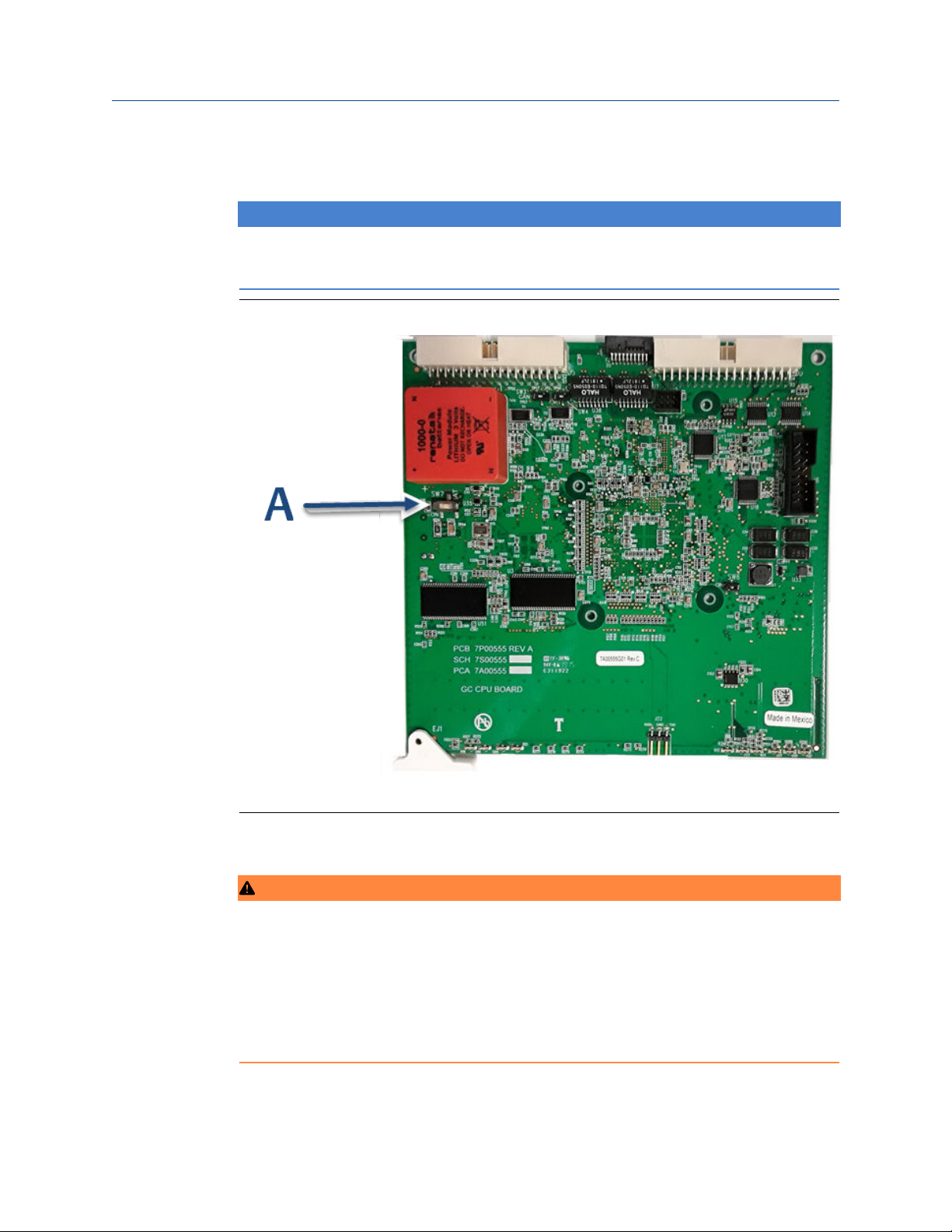
Reference Manual Installation and start-up
2-3-9000-744 June 2022
4.4 Electrical installation
NOTICE
Emerson switches off central processing unit (CPU) boards before shipping to preserve
their batteries. Before installing the CPU board, be sure to switch it on..
Figure 4-5: CPU board
4.4.1
A. SW7 battery power
Connect power supply
ON
WARNING
Electrical hazard
Failure to follow this warning may result in injury or death to personnel or cause damage
to equipment.
Ensure that the 24 Vdc input power source is switched Off before connecting the wires.
Ensure that the 24 Vdc power supply is safety extra low voltage (SELV) compliant by
suitable electrical separation from other circuits.
Rosemount 700XA 55
Page 56

Installation and start-up Reference Manual
June 2022 2-3-9000-744
NOTICE
Equipment damage
Failure to observe this precaution may damage equipment.
Check the gas chromatograph (GC) prior to wiring to determine if it is equipped for DC
power.
Procedure
1. Locate the plug-together termination block inside the electronics enclosure.
Figure 4-6: 24 Vdc power connection on the backplane
56 Emerson.com/Rosemount
Page 57

Reference Manual Installation and start-up
2-3-9000-744 June 2022
2. Bring the two leads in through one of the two possible entries on the lower
compartment. Connect to the termination plug provided with the GC.
Figure 4-7: Wiring entries on the under side of the lower enclosure
Attribute Wire color
+ (positive) red
– (negative) black
NOTICE
Do not disconnect the factory-installed ground wire.
The backplane board that connects to the 24 Vdc is protected from lead reversal by
the use of blocking diodes.
If the red (+) and black (-) leads are inadvertently reversed, no damage will occur;
however, the system will not have power.
3. Connect the DC power leads to the power disconnect switch that should be
properly fused.
The recommended fuse size is 8 amps.
Rosemount 700XA 57
Page 58
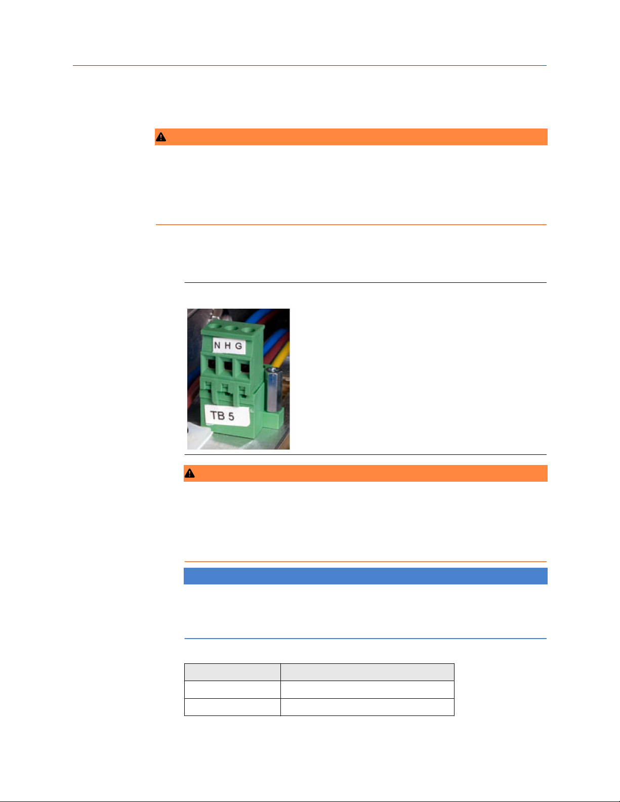
Installation and start-up Reference Manual
June 2022 2-3-9000-744
4.4.2 Connect optional AC/DC power converter
WARNING
Failure to follow this warning may result in injury or death to personnel or cause damage
to equipment.
Check the gas chromatograph (GC) prior to wiring to determine if it is equipped for
optional AC power.
Procedure
1. Locate the plug-together termination block inside the electronics enclosure, atop
the power supply and adjacent to the card cage.
Figure 4-8: AC/DC termination block
WARNING
Failure to follow this warning may result in injury or death to personnel or cause
damage to equipment.
Do not connect the AC power leads without first ensuring that the AC power source
is switched Off.
NOTICE
Failure to observe this precaution may cause damage to equipment.
Do not apply electrical power to the GC until all interconnections and external signal
connections have been verified and proper grounds have been made.
AC wiring is usually color coded as:
Label
Hot (H) Brown or black
Neutral (N) Blue or white
58 Emerson.com/Rosemount
Wire color
Page 59

Reference Manual Installation and start-up
2-3-9000-744 June 2022
Label Wire color
Ground (G) Green with yellow tracer or green
2. Bring the power leads in through the left entry on the bottom of the enclosure.
3. If necessary at remote locations, connect the GC chassis ground wire to an external
copper ground rod.
Related information
Signal wiring
Rosemount 700XA 59
Page 60

Installation and start-up Reference Manual
June 2022 2-3-9000-744
4.4.3 Connect gas lines
Procedure
1. Remove the plug from the 1/16-in sample vent tubing marked SV1 that is located
on the flow panel assembly. Depending on your configuration, there may also be a
second sample vent marked SV2. If so, remove its plug as well.
Figure 4-9: Sample vent and measure vent lines
A. Sample vent
B. Measure vent
• If desired, connect the sample vent lines to an external, ambient pressure vent. If
the vent line is terminated in an area exposed to wind, protect the exposed vent
with a metal shield.
• Use ¼-in or ⅜-in tubing for vent lines longer than 10 ft (3.05 m).
NOTICE
Do not discard the vent line plugs. They are useful when leak-checking the gas
chromatograph (GC) and its sample or gas line connections.
At this stage in the installation, the measure vent (MV) lines (labeled on the side of
the GC) should remain plugged until the GC has been checked for leaks. For regular
operation, however, the MV lines must be unplugged.
2. Connect the carrier gas to the GC.
The carrier gas inlet is labeled Carrier In and is a ¼-in T-fitting.
60 Emerson.com/Rosemount
Page 61

Reference Manual Installation and start-up
2-3-9000-744 June 2022
WARNING
Leak testing
All gas connections must be properly leak tested at installation.
Do not turn on gas until you have completely checked the carrier lines for leaks.
WARNING
EXPLOSION HAZARD
Failure to follow this warning may result in injury or death to personnel.
Do not turn on sample gas until you have completely checked the carrier lines for
leaks.
• Use stainless steel tubing to convey carrier gas.
• Use a dual-stage regulator with high-side capacity of 3,000 psig (206.84 barg)
and low-side capacity of 150 psig (10.34 barg).
• Carrier gas is fed from two bottles for carrier gas plumbing.
3. Connect calibration standard gas to the GC.
When installing the calibration standard gas line, ensure that the correct tubing
connection is made.
• Use ⅛-in stainless steel tubing to connect calibration standard gas unless the
application requires treated tubing.
• Use a dual-stage regulator with low-side capacity of up to 30 psig (2.07 barg).
Rosemount 700XA 61
Page 62
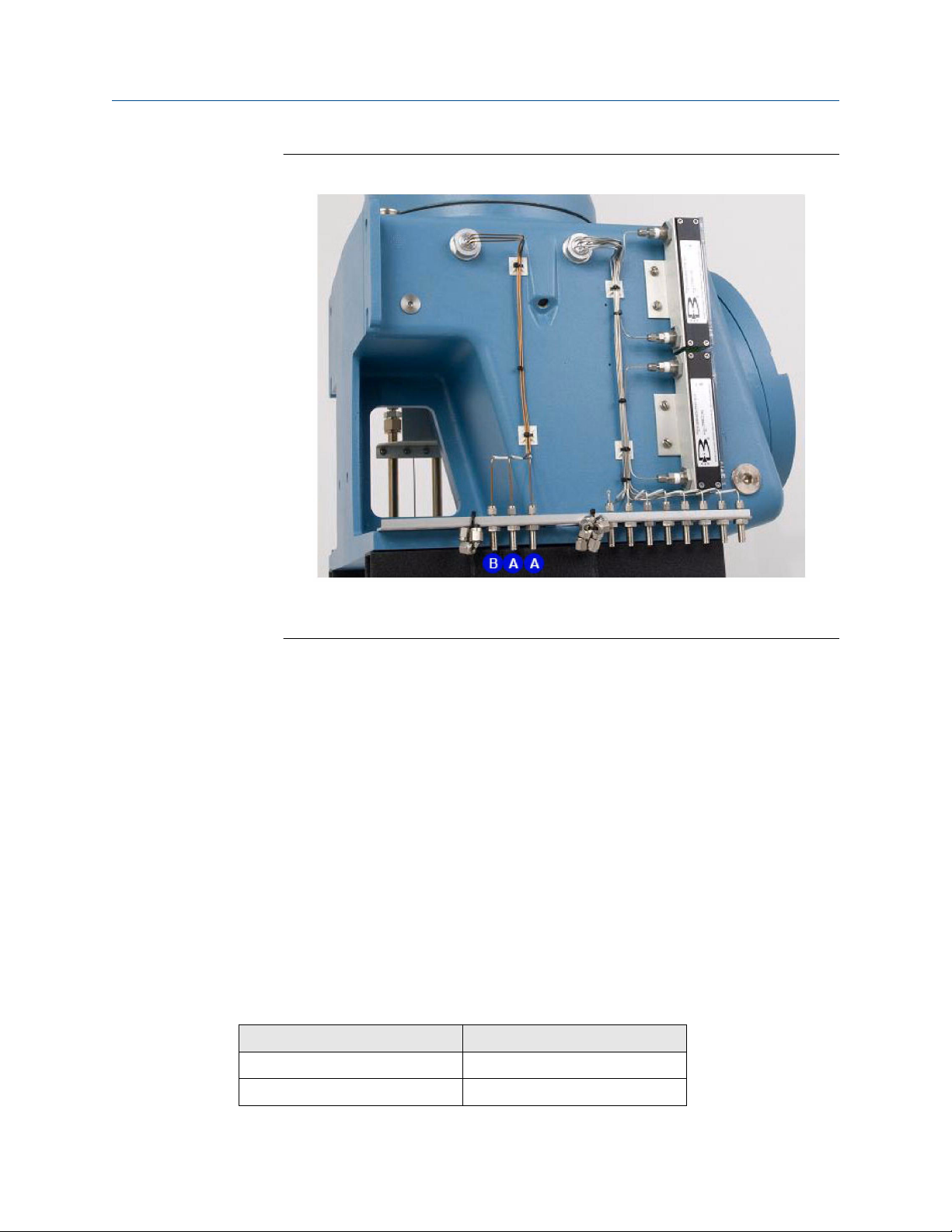
Installation and start-up Reference Manual
June 2022 2-3-9000-744
Figure 4-10: Sample stream inlets and calibration gas inlet
4.4.4
A. Sample stream inlets
B. Calibration gas inlet
4. Connect sample gas stream(s) to the GC.
• Use ⅛-in stainless steel tubing, as appropriate, to connect sample gas.
• Unless stated otherwise in the product documentation, ensure that the pressure
of the calibration and sample line is regulated at 15 psig (1.03 barg) to 20 psig
(1.38 barg).
Postrequisites
After all lines have been installed, proceed with leak-checking the carrier and sample lines.
Maximum effective distance by communication
protocol type
Table 4-1 lists the maximum distance at which the indicated protocol can transmit data
without losing effectiveness. If you need longer runs, use a repeater or other type of
extender to maintain the protocol's efficiency.
Table 4-1: Maximum distance for each communication protocol
Communication protocol Maximum distance
RS-232 50 ft (15 m)
RS-422/RS-485 4,000 ft (1,219 m)
62 Emerson.com/Rosemount
Page 63

Reference Manual Installation and start-up
2-3-9000-744 June 2022
Table 4-1: Maximum distance for each communication protocol
(continued)
Communication protocol Maximum distance
Ethernet (CAT5) 300 ft (91 m)
4.4.5 RS-485 serial port terminating resistors
To ensure correct communication with all hosts, place a 120-ohm terminating resistor
across the gas chromatograph (GC) serial port terminals on the RS-485 link. On a
multi-dropped link, install the terminating resistor on the last controller link only.
4.4.6 Installing and connecting to an analog modem card
The Rosemount 700XA has two slots (I/O Slot A and I/O Slot B) in the card cage for
installing an analog modem.
NOTICE
Rosemount MON2020 only recognizes Microsoft Windows®-compatible modems that
have all relevant drivers installed correctly.
NOTICE
Analog modems will only work with PSTN phone lines. Analog modems will not work with
VOIP networks.
The following four LEDs are provided on the modem for troubleshooting:
RI (Ring indicator)
CD (Carrier detect)
RX (Receive)
TX (Transmit
This LED flashes when it senses a ring. This LED should only flash
once per connection, because the modem automatically answers
on the first ring.
This LED glows green while connected to Rosemount MON2020.
This LED flashes while the gas chromatograph (GC) receives data
from Rosemount MON2020.
This LED flashes while the GC sends data to Rosemount MON2020.
Install the analog modem
Procedure
1. Start Rosemount MON2020 and connect to the gas chromatograph (GC).
2. Go to Tools → I/O Cards....
The I/O Cards window displays.
3. Change the Card Type for the appropriate in/out (I/O) slot to Communication
Module - Modem.
4. Click Save.
Rosemount 700XA 63
Page 64

Installation and start-up Reference Manual
June 2022 2-3-9000-744
Rosemount MON2020 displays the following message: The GC must be rebooted for
the ROC Card changes to take effect.
5. Click OK to dismiss the message.
6. Click OK to close the I/O Cards window.
7. Disconnect from the GC.
8. Turn off the GC.
9. Insert the analog modem card into the appropriate I/O slot in the GC’s card cage.
Ensure that the I/O slot matches the one you selected inStep 3.
10. Tighten the card’s screws to secure the modem in the slot.
11. Insert a telephone cable into the modem card’s RJ-11 socket.
12. Start the GC.
13. Return to Rosemount MON2020 and connect to the GC via its Ethernet connection.
14. Go to Application → Communication....
The Communication window displays. The appropriate I/O slot should be listed in
the first column (Label).
15. Set the Baud Rate for the analog modem card to 57600.
16. Make note of the I/O slot’s Modbus Id.
17. Click Save.
18. Click OK to close the Communication window.
19. Disconnect from the GC.
4.4.7
Connect directly to a personal computer (PC) using the
gas chromatograph's (GC’s) Ethernet1 port
The GC’s DHCP server feature and its Ethernet1 port on the backplane at J22 allows you to
connect directly to the GC. This is a useful feature for GCs that are not connected to a local
area network; all that is needed is a PC, typically a notebook computer, and a CAT5
Ethernet cable.
Procedure
1. Plug one end of the Ethernet cable into the PC’s Ethernet port and the other end
into the GC’s RJ45 socket on J22 on the backplane.
2. Locate switch at SW1 directly beneath the Ethernet port on the backplane. Place
SW1 in the On position.
The switch labeled 2 is for future use.
64 Emerson.com/Rosemount
Page 65

Reference Manual Installation and start-up
2-3-9000-744 June 2022
Figure 4-11: SW1 switches on the backplane
Note
The GC can be connected (or remain connected) to the local network on Ethernet2
(TB11) on the backplane while the DHCP feature on Ethernet1 is being used.
This starts the GC’s DHCP server feature. The server typically takes approximately
20 seconds to initialize and start up.
3. Wait for 20 seconds and then do the following to ensure that the server has
provided an Internet protocol (IP) address to the PC:
a) From the PC, go to Start → Control Panel → Network Connections.
The Network Connections window lists all dial-up and local area network
(LAN)/high-speed Internet connections installed on the PC.
b) In the list of LAN / high speed Internet connections, find the icon that
corresponds to the PC-to-GC connection and check the status that displays
beneath the Local Area Connection.
It should show the status as Connected. The PC is now capable of connecting
to the GC.
If the status is Disconnected, it may be that the PC is not configured to
accept IP addresses; therefore, do the following:
4. Right-click the Properties icon.
The Local Area Connection Properties window displays.
5. Scroll to the bottom of the Connection list box and select Internet Protocol (TCP/
IP).
6. To configure the PC to accept IP addresses issued from the GC, select the Obtain an
IP address automatically and Obtain DNS server address automatically check
boxes.
7. Click OK to save the changes and to close the Internet Protocol (TCP/IP) Properties
window.
8. Click OK to close the Local Area Connection Properties window.
9. Return to the Network Connections window and confirm that the appropriate icon’s
status reads Connected.
Rosemount 700XA 65
Page 66

Installation and start-up Reference Manual
June 2022 2-3-9000-744
Postrequisites
If the icon still reads Disconnected refer to Troubleshoot DHCP connectivity issues.
NOTICE
If you power cycle the GC, you will lose connectivity.
4.4.8 Connect to the gas chromatograph (GC) using
Rosemount MON2020
To connect to the GC using the RJ45 Ethernet1 connection:
Procedure
1. Start Rosemount MON2020.
The Connect to GC window displays.
2. Locate the default Direct-DHCP under the GC Name column.
This GC directory is created automatically when Rosemount MON2020 is installed.
You can rename the GC, but do not change the IP address that it references,
192.168.135.100.
3. Click the associated Ethernet button.
Rosemount MON2020 prompts you to enter a user name and password.
4. Enter your user name and password.
5. Rosemount MON2020 connects you to the GC.
66 Emerson.com/Rosemount
Page 67

Reference Manual Installation and start-up
2-3-9000-744 June 2022
4.4.9 Troubleshoot DHCP connectivity issues
1. Ensure that the gas chromatograph (GC) is up and running. If equipped with a
front panel, check the CPU LED on the front panel; a green light means that the
GC is operational. If equipped with a local operator interface (LOI), ensure that
the LOI is communicating with the GC.
2. Check that the SW1 switch is in the On position.
3. Check the following connections:
a) If you are using a Ethernet straight-through cable, ensure that the
personal computer (PC) has an Ethernet network interface card with
auto-MDIX.
b) If your Ethernet network interface card does not support auto-MDIX,
ensure that you are using an Ethernet crossover patch cable.
Rosemount 700XA 67
Page 68

Installation and start-up Reference Manual
June 2022 2-3-9000-744
c) Check to see if the GC's central processing unit (CPU) board link lights are
on.
See Figure 4-12. The three Ethernet1 LEDs are located on the front
bottom edge of the card. If link lights are off, check your connections.
Figure 4-12: CPU board link lights
A. CPU board
B. Ethernet link lights
4. Do the following to ensure that your network adapter is enabled:
a) Go to Start → Control Panel → Network Connections....
b) Check the status of the Local Area Connection icon. If the status appears
as Disabled, right-click the icon and select Enable from the context
menu.
5. Do the following to try to repair the network connection:
a) Go to Start → Control Panel → Network Connections....
b) Right-click the Local Area Connection icon and select Repair from the
context menu.
68 Emerson.com/Rosemount
Page 69

Reference Manual Installation and start-up
2-3-9000-744 June 2022
4.4.10 Connect directly to a personal computer (PC) using the
gas chromatograph's (GC's) serial port
The GC’s serial port at J23 on the backplane allows a PC with the same type of port to
connect directly to the GC. This is a useful feature for a GC that is located in an area
without Internet access; all that is needed is a PC running Microsoft Windows®, a notebook
computer, and a straight-through serial cable.
Figure 4-13: J23 serial port
A. J23 port
To set up the PC for the direct connection:
Procedure
1. Install the communications cable between two computers:
a) Navigate to Start → Control Panel and select the Phones and Modem
Options icon.
The Phones and Modem Options dialog window displays.
b) Select the Modem tab and click Add….
The Add Hardware Wizard displays.
c) Select the Don’t detect my modem; I will select it from a list check box and
then click Next.
d) Click Have Disk.
The Install from Disk dialog window appears.
e) Click Browse
Rosemount 700XA 69
Page 70

Installation and start-up Reference Manual
June 2022 2-3-9000-744
The Browse dialog window displays.
f) Navigate to the Rosemount MON2020 install directory (typically C:\Program
Files (x86)\Emerson Process Management\MON2020) and select Daniel Direct
Connection.inf.
g) Click Open.
You return to the Install from Disk dialog window.
h) Click OK.
You return to the Add Hardware Wizard.
i) Click Next.
j) Select an available serial port and click Next.
The Hardware Installation dialog window displays.
k) Click Continue Anyway.
After the driver is installed, you return to the Add Hardware Wizard.
l) Click Finish.
You return to the Phones and Modems dialog window. The Daniel Direct
Connect modem should be listed in the Modem column.
2. Start Rosemount MON2020 and do the following to create a GC connection for the
Daniel Direct Connection modem:
a) Go to File → GC Directory....
The GC Directory window displays.
b) Select Add from the GC Directory window’s File menu.
A New GC row is added to the bottom of the table.
c) Select the New GC text and type a new name for the GC connection.
d) Select the new GC’s Direct check box.
e) Click the Direct button located at the bottom of the GC Directory window.
The Direct Connection Properties window displays.
f) Select Communications cable between two computers (COM n) from the
Port dropdown menu.
Note
The letter n stands for the COM port number.
g) Select 57600 from the Baud Rate dropdown menu.
h) Click OK to save the settings.
You return to the GC Directory window.
i) Click OK to save the new GC connection and to close the GC Directory
window.
3. Connect one end of the direct connect cable to the GC’s serial port at J23 on the
backplane.
70 Emerson.com/Rosemount
Page 71

Reference Manual Installation and start-up
2-3-9000-744 June 2022
4. Connect the other end of the direct connect cable to the PC’s corresponding serial
port.
5. Go to Chromatograph → Connect....
The Connect to GC window displays.
6. Click Direct to connect to the GC using the serial cable connection.
4.4.11 Connect directly to a personal computer (PC) using the
gas chromatograph's (GC’s) wired Ethernet terminal
The Rosemount 700XA has a wired Ethernet terminal at TB11 on the backplane that you
can connect to with a static Internet protocol (IP) address. All that is needed is a PC,
typically a notebook computer, and a two-wire, twisted pair CAT5 Ethernet cable with one
of its plugs removed to expose the wires.
Figure 4-14: Crimped CAT5 cable
NOTICE
The GC can be connected (or remain connected) to the local network on Ethernet2 (TB11)
on the backplane while the DHCP feature is being used.
Figure 4-15: Wired Ethernet terminal block on the backplane
Rosemount 700XA 71
Page 72

Installation and start-up Reference Manual
June 2022 2-3-9000-744
Procedure
1. Use the following schematics as a guide to wiring the GC via its four-wire connector
at TB11.
Figure 4-16 shows the traditional wiring scheme. Figure 4-17 shows how to wire a
CAT5 cable without the RJ45 plug.
Figure 4-16: Field wiring to TB11
Figure 4-17: CAT5 wiring to TB11
2. Once you have wired the cable to the Ethernet terminal, plug the other end into a
PC or a wall jack.
72 Emerson.com/Rosemount
Page 73

Reference Manual Installation and start-up
2-3-9000-744 June 2022
4.4.12 Assign a static Internet protocol (IP) address to the gas
chromatograph (GC)
Procedure
1. Start Rosemount MON2020 and log in to the GC using a direct Ethernet connection.
2. Go to Application → Ethernet ports....
The Ethernet Ports window displays.
3. Depending upon the Ethernet port to which you want to assign a static IP address,
do the following:
a) The Ethernet port at TB11: Enter the appropriate values in the Ethernet2 IP
Address, the Ethernet 2 Subnet, and the Default Gateway fields.
b) The RJ45 Ethernet port at J22: Enter the appropriate values in the Ethernet1
IP Address, the Ethernet1 Subnet, and the Default Gateway fields.
Note
See your information technology (IT) staff to obtain IP, subnet, and gateway
addresses.
Important
To configure a Ethernet IP address using the local operator interface (LOI),
refer to Figure A-55.
4. Click OK.
5. Log off the GC.
Rosemount 700XA 73
Page 74
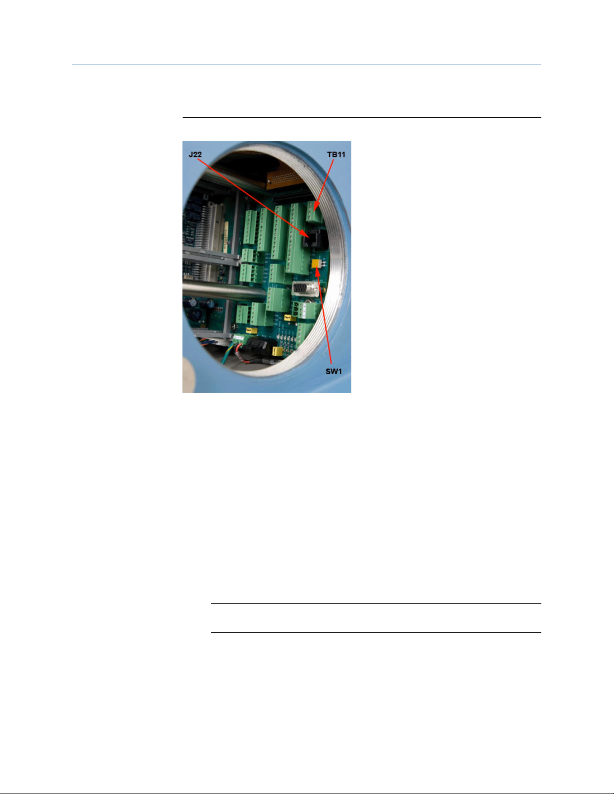
Installation and start-up Reference Manual
June 2022 2-3-9000-744
6. Access the backplane, which is located in the GC’s lower enclosure.
Figure 4-18: Port locations on the backplane
7. If you are setting up a static IP address for the Ethernet1 port at J22, and you also
intend to connect to your company’s local area network, do the following:
a) Locate the set of dip switches, labeled 1 and 2 , at SW1 on the backplane.
SW1 is located directly beneath the Ethernet port at J22 .
b) Move dip switch 1 to its left position (Off).
This disables the DHCP server.
8. To connect to the GC:
a) Start Rosemount MON2020 and select File → GC Directory....
The GC Directory window displays.
b) Select Add.
Rosemount MON2020 adds a new GC profile to the end of the table.
Note
You can name the GC’s profile as well as add a short description.
c) Select the new profile and click Ethernet... Enter the GC’s static IP address in
the IP address field.
d) Click OK.
The Ethernet Connection Properties for New GC window closes.
74 Emerson.com/Rosemount
Page 75

Reference Manual Installation and start-up
2-3-9000-744 June 2022
9. Click Save to save the new profile.
10. Click OK to close the GC Directory window.
11. Select Chromatograph → Connect... to connect to the GC or click .
The Connect to GC window displays. The newly created GC profile should be listed in
the table.
12. Locate the new GC profile and click the Ethernet button that is associated with it.
The Login window displays.
13. Enter a User Name and User Pin and click OK.
4.4.13 Wiring the discrete digital inputs and outputs
The backplane has five discrete outputs and five discrete inputs. Refer to the Rosemount
MON2020 Software for Gas Chromatographs Reference Manual to learn how to configure
the digital outputs.
Related information
Wire a ROC800 digital output (DO) module
Wire the discrete digital inputs
WARNING
Electric shock
Failure to observe this precaution may cause serious personal injury or death.
The equipment operates using mains voltage that is dangerous to life. Make sure that the
circuit breakers are set to OFF and tagged off before removing the top cover or opening
the front cover.
WARNING
Explosion
Failure to de-energize the analyzer may cause an explosion and severely injure personnel.
Before opening the analyzer, disconnect all electrical power and ensure that the area is
free of explosive gases.
Keep cover tight while circuits are live.
Use cables or wires suitable for the marked "T" ratings.
Cover joints must be cleaned before replacing the cover.
Conduit runs to the enclosure must have sealing fitting adjacent to enclosure.
To connect digital signal input lines to the gas chromatograph (GC):
Procedure
1. Disconnect power to the analyzer and allow the components to cool for at least five
minutes.
2. Open the electronics enclosure door and access the back plane.
Rosemount 700XA 75
Page 76

Installation and start-up Reference Manual
June 2022 2-3-9000-744
3. Make the digital input wiring connections on the backplane at TB7.
Figure 4-19: TB7 on the backplane
Note
The discrete digital input terminals on the backplane are self-powered. Devices
connected to the digital input will be powered by the GC's dedicated isolated 24 V
power supply.
Note
The discrete digital input terminals are optically isolated from the GC's other
circuitry.
4. Route digital input/output (I/O) lines away from the sensitive detector lines (on the
left side of the backplane) and away from the analog inputs and outputs.
There are connections for five digital inputs on the backplane at TB7, as indicated in
Table 4-2.
Table 4-2: Discrete digital inputs at TB7
TB7 Function
Pin 1 Digital input 1
Pin 2 Digital input return
Pin 3 Digital input 2
Pin 4 Digital input return
Pin 5 Digital input 3
Pin 6 Digital input return
Pin 7 Digital input 4
Pin 8 Digital input return
76 Emerson.com/Rosemount
Page 77
Reference Manual Installation and start-up
2-3-9000-744 June 2022
Table 4-2: Discrete digital inputs at TB7 (continued)
TB7 Function
Pin 9 Digital input 5
Pin 10 Digital input return
Wire a ROC800 digital input (DI) module
To connect the ROC800 DI module to a field device:
Procedure
1. Expose the end of the wire to a maximum length of 0.25 in (6.4 mm).
NOTICE
We recommend twisted-pair cables for in/out (IO) signal wiring. The module's
terminal blocks accept wire sizes between 12 and 22 American wire gauge (AWG).
Allow some slack when making connections to prevent strain.
NOTICE
Failure to follow this notice may cause a short circuit and damage equipment. Allow
only a minimal amount of bare wire to prevent short circuits.
2. Insert the exposed end into the clamp beneath the termination screw.
3. Tighten the screw.
Rosemount 700XA 77
Page 78
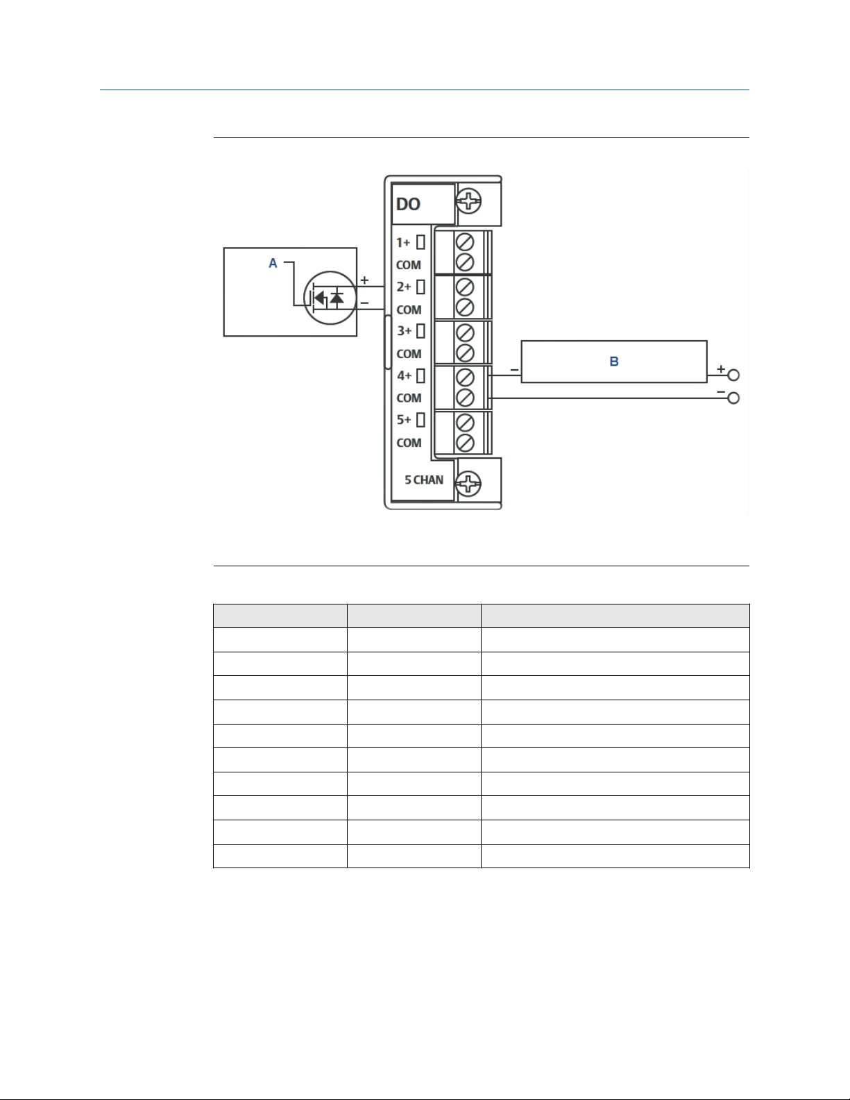
Installation and start-up Reference Manual
June 2022 2-3-9000-744
Figure 4-20: Typical wiring
A. Control
B. Discrete device (externally powered)
Table 4-3: ROC800 discrete digital wiring
Terminal Label Definition
1 1 Channel 1 Positive
2 2 Channel 2 Positive
3 3 Channel 3 Positive
4 4 Channel 4 Positive
5 5 Channel 5 Positive
6 6 Channel 6 Positive
7 7 Channel 7 Positive
8 8 Channel 8 Positive
9 COM Common
10 COM Common
78 Emerson.com/Rosemount
Page 79
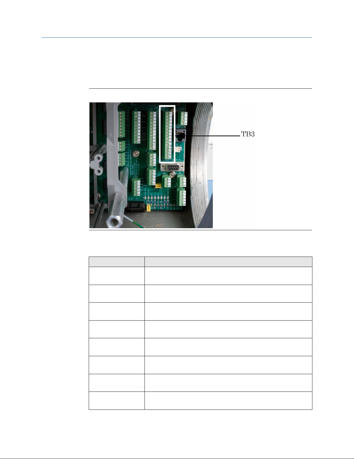
Reference Manual Installation and start-up
2-3-9000-744 June 2022
Wiring the discrete digital outputs
The discrete outputs are located on TB3, which is a 15-pin connector, and have five FormC relays on the backplane. All contact outputs have a rating of 1A at 30 Vdc.
Figure 4-21: TB3 on the backplane
Table 4-4 lists the discrete digital output function for each pin on the TB3 connector.
Table 4-4: Discrete digital outputs on TB3
TB3 Function
Pin 1 Normally closed (NC1)
DIG_OUT NC1
Pin 2 ARM1
DIG_OUT ARM1
Pin 3 Normally open (NO1)
DIG_OUT NO1
Pin 4 NC2
DIG_OUT NC2
Pin 5 ARM 2
DIG_OUT ARM2
Pin 6 NO2
DIG_OUT NO2
Pin 7 NC3
DIG_OUT NC3
Pin 8 ARM3
DIG_OUT ARM3
Rosemount 700XA 79
Page 80

Installation and start-up Reference Manual
June 2022 2-3-9000-744
Table 4-4: Discrete digital outputs on TB3 (continued)
TB3 Function
Pin 9 NO3
DIG_OUT NO3
Pin 10 NC4
DIG_OUT NC4
Pin 11 ARM4
DIG_OUT ARM4
Pin 12 NO4
DIG_OUT NO4
Pin 13 NC5
DIG_OUT NC5
Pin 14 ARM5
DIG_OUT ARM5
Pin 15 NO5
DIG_OUT NO5
Note
Form-C relays are single-pole double-throw (SPDT) relays that have three positions:
normally closed (NC); an intermediate position, also called the make-before-break
position (ARM); and normally open (NO).
Related information
List of engineering drawings - Rosemount 700XA
Optional discrete digital inputs (DI)
When plugged into one of the optional card slots in the card cage, the Emerson ROC800
DI card provides eight additional discrete digital inputs. The discrete digital inputs can
monitor the status of relays, open-collector or open-drain type solid-state switches, and
other two-state devices.
For more information, see ROC800-Series Discrete Input Module at Emerson’s ROC 800-
Series website.
80 Emerson.com/Rosemount
Page 81

Reference Manual Installation and start-up
2-3-9000-744 June 2022
Figure 4-22: Optional digital in/out (I/O) modules
Wire a ROC800 digital output (DO) module
Figure 4-23: Discrete discrete output wiring
A. Control
B. Discrete device (externally powered)
Rosemount 700XA 81
Page 82

Installation and start-up Reference Manual
June 2022 2-3-9000-744
Terminal Label Definition
1 1+ Positive discrete output
2 COM Discrete output return
3 2+ Positive discrete output
4 COM Discrete output return
5 3+ Positive discrete output
6 COM Discrete output return
7 4+ Positive discrete output
8 COM Discrete output return
9 5+ Positive discrete output
10 COM Discrete output return
To connect the ROC800 DO module to a field device:
Procedure
1. Expose the end of the wire to a maximum length of 0.25 in (6.4 mm).
NOTICE
We recommend twisted-pair cables for in/out (IO) signal wiring. The module's
terminal blocks accept wire sizes between 12 and 22 American wire gauge (AWG).
Allow some slack when making connections to prevent strain.
NOTICE
Failure to follow this notice may cause a short circuit and damage equipment. Allow
only a minimal amount of bare wire to prevent short circuits.
2. Insert the exposed end into the clamp beneath the termination screw.
3. Tighten the screw.
82 Emerson.com/Rosemount
Page 83

Reference Manual Installation and start-up
2-3-9000-744 June 2022
4.4.14 Wiring the analog inputs
All Rosemount 700XA gas chromatographs (GCs) have at least two analog inputs. An
additional four analog inputs are available with a ROC800 AI-16 card that can be installed
into one of the optional slots in the card cage.
Analog inputs on the backplane
There are two analog input connections on the backplane at terminal block 10 (TB10).
Figure 4-24: TB10 on the backplane
Table 4-5: Analog inputs TB10
TB10 Function
Pin 1 +AI_1
Pin 2 -AI_1
Pin 3 +AI_2
Pin 4 -AI_2
Rosemount 700XA 83
Page 84

Installation and start-up Reference Manual
June 2022 2-3-9000-744
Analog inputs settings switches
Figure 4-25 shows how to wire two analog inputs (TB10).
Figure 4-25: Customer wiring for analog inputs
A. Backplane
B. Analog inputs
C. Analog input 1
D. Analog input ground
E. Analog input 2
F. Cable
G. Customer devices
H. Customer 4-20 mA outputs
Figure 4-26 shows the factory settings for the analog input switches that are located on
the base input/output (I/O) board. These analog inputs are set to accept a current (4-20
mA) source.
Figure 4-26: Factory settings for analog input switches
Use the Hardware → Analog Inputs menu in Rosemount MON2020 to configure the
analog inputs.
Note
To set an analog input to accept a voltage (0-10 VDC) source, flip the appropriate switch in
the opposite direction from that shown in Figure 4-26.
84 Emerson.com/Rosemount
Page 85

Reference Manual Installation and start-up
2-3-9000-744 June 2022
Select the input type for an analog input
You can set an analog input to either voltage (0-10 V) or current (4-20 mA) by flipping the
appropriate switches on the base input/output (I/O) board .
Procedure
1. Turn off the gas chromatograph (GC).
2. Locate and remove the base I/O board, which is in the card cage in the GC’s lower
enclosure.
3. To set analog input #1 to current, locate SW1 on the backplane base I/O board and
push the switches up, toward the card ejector; to set the analog input to voltage,
push the switches down, away from the card ejector.
4. To set analog input #2 to current, locate SW2 on the base I/O board and push the
switches up, toward the card ejector; to set the analog input to voltage, push the
switches down, away from the card ejector.
5. Replace the base I/O board in the card cage.
6. Close and fasten the electronic enclosure door.
7. Apply power to the GC.
8. Select Hardware → Analog Inputs....
The Analog Inputs window displays.
9. To set the analog input to current, select mA from the mA/Volts drop-down list for
the appropriate analog input; to set the analog input to voltage, select Volts from
the mA/Volts drop-down list for the appropriate analog input.
10. Click Save to save the changes and keep the window open or click OK to save the
changes and close the window.
Rosemount 700XA 85
Page 86

Installation and start-up Reference Manual
June 2022 2-3-9000-744
Typical wiring for line-powered transmitters
Figure 4-27 shows the most common wiring plan for supplying power to two 4-20 mA
transmitters, such as pressure sensor transmitters.
Figure 4-27: Typical wiring for line-powered transmitters
A. Backplane
B. Customer transmitter
C. Analog inputs
D. Transmitter 4-20 mA output
Optional analog inputs (AI)
When plugged into one of the optional card slots on the card cage, the ROC800 AI-16 card
provides four additional analog inputs.
The AI channels are scalable, but are typically used to measure either a 4-20 mA analog
signal or a 1-5 Vdc signal. If required, the low end of the AI module’s analog signal can be
calibrated to zero. For more information, see Analog Input Modules (ROC800 Series).
86 Emerson.com/Rosemount
Page 87

Reference Manual Installation and start-up
2-3-9000-744 June 2022
Figure 4-28: Optional in/out (I/O) expansion card slots
A. Optional card slots
Wire a ROC800 AI-16 module
NOTICE
Electrostatic discharge (ESD)
Operators and technicians must wear an electrostatic wrist strap when handling printed
circuit cards to prevent shorting the boards through static electricity. Do not install or
remove the printed circuit assemblies while power is applied to the device. Keep electrical
components and assemblies in their protective (conductive) carriers or wrapping until
ready for use. Use the protective carrier as a glove when installing or removing printed
circuit assemblies.
Rosemount 700XA 87
Page 88

Installation and start-up Reference Manual
June 2022 2-3-9000-744
Figure 4-29: Typical ROC800 wiring
A. 1-5 volt device, externally powered
B. 1-5 volt device, ROC800 powered
C. Current loop device 4-20 mA, ROC800 powered
To connect the ROC800 AI-16 module to a device:
Procedure
1. Expose the end of the wire to a maximum length of 0.25 in (6.4 mm).
Note
We recommend twisted-pair cables for in/out (I/O) signal wiring. The module’s
terminal blocks accept wire sizes between 12 and 22 American wire gauge (AWG).
Allow some slack when making connections to prevent strain.
NOTICE
Electrical hazard
Exposing bare wires may cause a short circuit and damage equipment.
Keep exposed bare wires to a minimum.
2. Insert the exposed end into the clamp beneath the termination screw.
3. Tighten the screw.
There are two dip switches on the terminal block side of the module that can be
used to set a 250 Ω resistor in or out of circuit for each analog input.
To put an analog input’s resistor in circuit, flip the appropriate dip switch to I; to put
an analog input’s resistor out of circuit, flip the appropriate dip switch to V.
88 Emerson.com/Rosemount
Page 89

Reference Manual Installation and start-up
2-3-9000-744 June 2022
Calibrate a ROC800 AI-16 module
Prerequisites
To calibrate the ROC800 AI-16 module you must have a personal computer (PC) with the
ROCLINK™ 800 Configuration software installed and open.
See Emerson’s ROC 800-Series page for details, downloads, and manuals.
Procedure
1. Go to Configure → I/O → RTD Points → Calibration.
2. Select an analog input.
3. Click Update to request one value update from the input.
4. Click Freeze to stop the values of the input from being updated during calibration.
Note
If you are calibrating a temperature input, disconnect the RTD sensor and connect a
decade box or comparable equipment to the RTD terminals of the ROC card.
4.4.15
5. Click Calibrate.
6. Enter a value for Set Zero after stabilization.
7. Enter a value for Set Span after stabilization.
8. Enter values for up to three Midpoints one at a time or click Done if you are not
configuring midpoints.
9. Click OK to close the main calibration window and unfreeze the associated inputs.
Postrequisites
To calibrate the inputs for another analog input, return to Step 1.
Analog output wiring
The Rosemount 700XA has at least six analog outputs. An additional four analog inputs are
available with an ROC800 AO card that can be installed into one of the optional slots in the
card cage.
Rosemount 700XA 89
Page 90
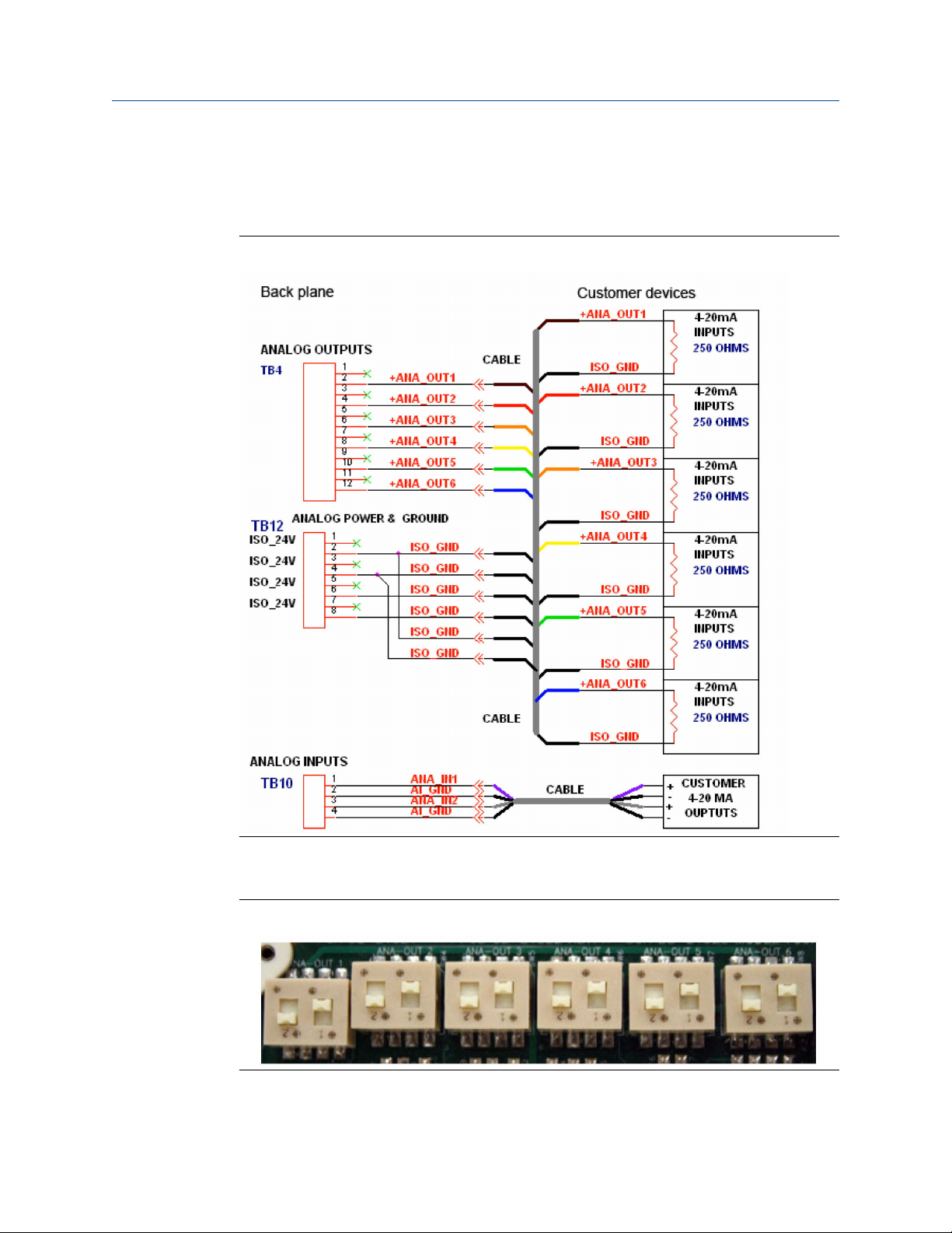
Installation and start-up Reference Manual
June 2022 2-3-9000-744
Factory settings for analog output switches
Figure 4-30 shows how to wire up to six devices to the analog outputs that are located on
the backplane. It also shows how to wire up to two analog inputs.
Figure 4-30: Wiring for six analog outputs
Figure 4-31 shows the factory settings for the analog output switches that are located on
the base in/out (I/O) board.
Figure 4-31: Factory settings for analog output switches
90 Emerson.com/Rosemount
Page 91

Reference Manual Installation and start-up
2-3-9000-744 June 2022
Wire customer externally-powered analog outputs
It is possible to furnish power to each analog output while maintaining isolation between
channels.
Procedure
Use Figure 4-32 to provide power wiring to each analog output while maintaining isolation
between channels.
Figure 4-32: Wiring for customer-powered analog outputs
A. Backplane
B. Customer devices
C. Analog outputs
D. Inputs
Figure 4-32 shows the settings for the analog outputs switches, located on the base input/
output (I/O) board, that are necessary to provide power to each analog output while
maintaining isolation between channels.
Rosemount 700XA 91
Page 92

Installation and start-up Reference Manual
June 2022 2-3-9000-744
Figure 4-33: Settings for analog output switches
The settings for the analog outputs connections located on the backplane are necessary to
provide power to each analog output while maintaining isolation between channels.
Optional analog outputs
When plugged into one of the optional card slots on the card cage, the ROC800 AO card
provides four additional analog outputs. Each channel provides a 4 to 20 mA current signal
for controlling analog current loop devices.
For more information, see Emerson's ROC 800-Series website.
Connect ROC800 analog output (AO) module to a field device
Procedure
1. Expose the end of the wire to a maximum length of 0.25 in (6.4 mm).
Note
We recommend using twisted-pair cables for in/out (I/O) signal wiring. The
module’s terminal blocks accept wire sizes between 12 and 22 American wire
gauge (AWG). Expose minimal bare wire to prevent short circuits. Allow some slack
when making connections to prevent strain.
2. Insert the exposed end into the clamp beneath the termination screw.
3. Tighten the screw.
4. Close the electronics enclosure door and apply power to the gas chromatograph
(GC).
5. Run Rosemount MON2020 and connect to the GC.
92 Emerson.com/Rosemount
Page 93

Reference Manual Installation and start-up
2-3-9000-744 June 2022
4.4.16 Configure analytical train
Use the Analytical Train Configuration window for multiple analysis clocks to assign the
valves, discrete outputs (DO), detectors, electronic pressure controls (EPCs), and heaters
to each train and then assign each train to its respective analysis clock.
Figure 4-34: Analytical Train Configuration window
Procedure
1. Assign the usage of valves and DO to Analyzer# on Hardware → Valves, Hardware
→ Detectors, Hardware → Discrete Outputs, Hardware → EPC, and Hardware →
Heaters screens.
2. Open the Application → Analytical Train Configuration screen.
You can use the Filter Selections drop-down list to filter by the type of hardware you
are interested in. The options are:
• All
• Detectors
• Valves
• Discrete Output
• EPC
• Heaters
By default, All is selected, and all types of hardware are displayed. To filter by a
certain type of hardware, select it from the list. Then only rows with the selected
hardware will be displayed.
3. Click Discrete Output and Valves. Assign the respective DOs, valves, and detectors
to each analytical train.
The valves are assigned with Usage as Analyzer# displayed on this screen. All
available detectors are also displayed on this screen. You cannot configure the same
Rosemount 700XA 93
Page 94
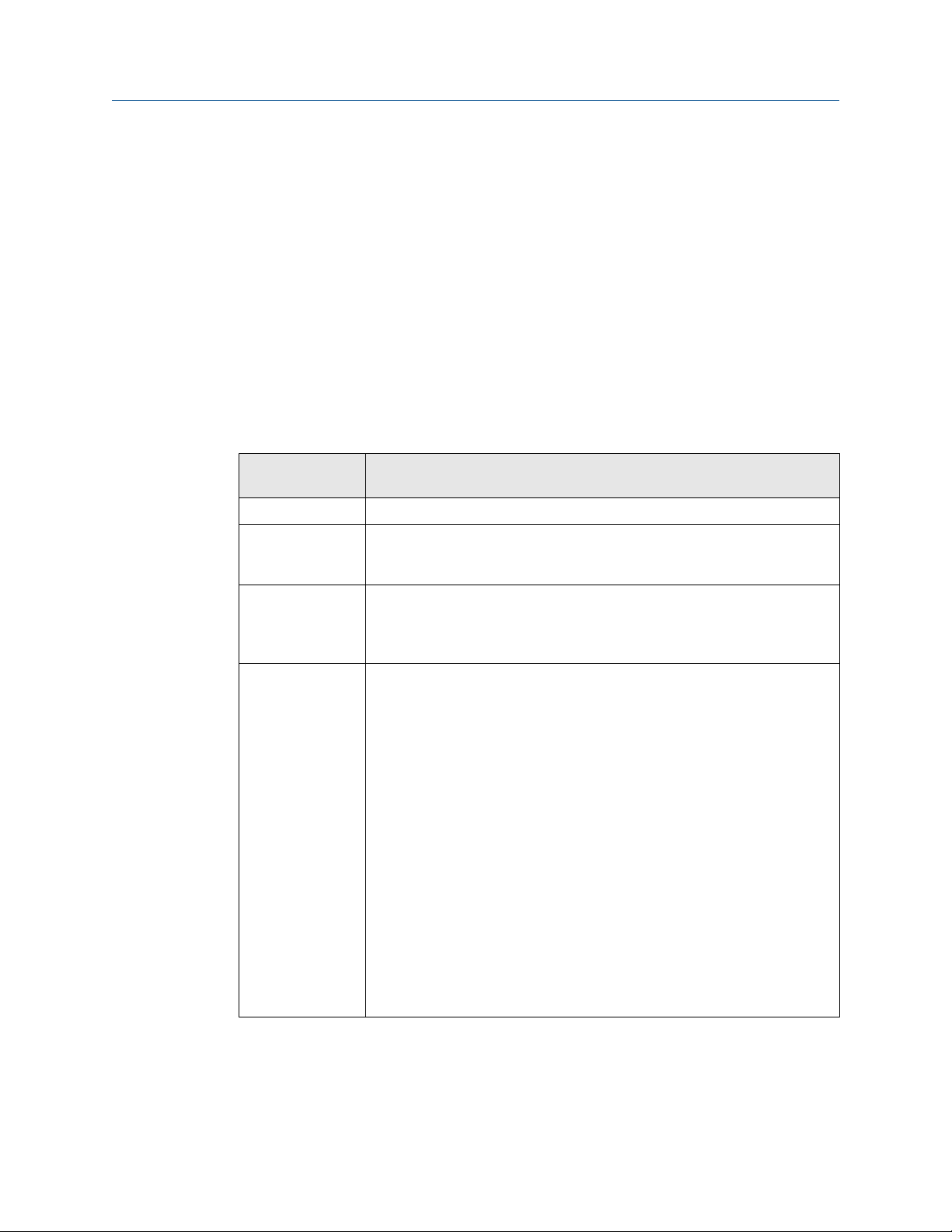
Installation and start-up Reference Manual
June 2022 2-3-9000-744
valve or DO to multiple trains, but you can configure the same detector to multiple
trains.
4. On the Application → Timed Events screen, filter the configured events as per train
selection by selecting the Train# check box.
4.4.17
Use this feature to configure a single analysis clock or multiple clocks.
One analysis clock can be considered as one virtual gas chromatograph (GC) that has
independent Sample Loop, Analytical Path, and Timed Event tables.
Multiple analysis clocks can run independently to analyze multiple streams at the same
time. Emerson sets the number of analysis clocks at the factory per the mechanical
configurations of the GC.
Mechanical
configurations
Trains (1 - 6) The configured trains that are used by the analysis
Default Stream
Sequence (Def
Strm Seq)
Purge Duration The amount of time, in seconds, to purge the stream before starting an
Energy Value
Check
Description
Sets the default sequence to be used by the indicated analysis during autosequencing.
analysis, calibration, or validation run. The default value is 60 SEC. Purging
allows sample gas to flow through the sample loop prior to beginning the
run.
If enabled, the GC analyzes the calibration gas as an unknown stream and
computes its energy value. The GC then compares this value to the Cal Gas
Cert CV and determines if the calibration gas's energy value is within the CV
Check Allowed Deviation. If it isn't, the GC triggers the Energy Value Invalid
alarm. The following conditions must be met before the GC can perform a EV
Check:
• The EV Check flag on the System screen must be enabled.
• At least one stream must be set up in the Streams screen as a calibration
stream, and the Auto flag for this stream must be enabled.
The EV Check is performed under any of the following circumstances:
• During a warm start that follows a power failure during normal operation.
The GC waits for the heater and electronic pressure controller (EPC) to
reach their respective set points and stabilize. It then analyzes the
calibration gas as an unknown stream and identifies the peaks. If all the
component peaks are identified, the GC computes the calibration gas'
energy value and performs the EV Check.
• After a successful calibration, the GC computes the gas's energy value
with the new response factors and performs the EV Check
1. Press Insert to add a new analysis.
2. Press Delete to delete an analysis.
94 Emerson.com/Rosemount
Page 95

Reference Manual Installation and start-up
2-3-9000-744 June 2022
4.5 Leak checking and purging for first calibration
CAUTION
EQUIPMENT DAMAGE
Failure to clean and dry the tubing may compromise the integrity of the analyzer or its
warranty.
Make sure all tubing is clean and dry internally.
Prior to installation, blow the tubing free of internal moisture, dust, or other
contaminants.
Verify that all electrical connections are correct and safe and then turn the gas
chromatograph (GC) on.
4.5.1
Check the gas chromatograph (GC) for leaks
Prerequisites
Leak checking carrier and calibration gas lines requires power and a personal computer
(PC) connected to the GC.
Note
Refer to the analyzer's drawing documentation package that shipped with the GC for leak
checking and identifying vents.
Emerson tested the GC and fittings for leaks at the factory prior to shipment.
Procedure
1. Plug the measure vent (labeled MV) vent line if it is open.
Leave the SV or sample vent line open or unplugged.
2. Slowly pressurize each line in turn; then block in the line, making sure the pressure
holds.
For example, the carrier gas line should be slowly brought up to 100 psig
(6.89 barg)± two percent with the dual-stage regulator at the carrier gas cylinder,
and the actuation pressure should be 100 psig (6.89 barg) maximum.
3. After two minutes, shut the carrier gas bottle valve and observe the high side
regulator gauge on the carrier gas bottle.
a. The gauge should not bleed down more than 100 psig (6.89 barg) in ten
minutes.
b. If helium is lost at a faster rate, leaks are usually found between the carrier
gas bottle and the analyzer. Check and tighten all connections, as well as the
dual-stage regulator.
4. When the leak check is complete, reopen the helium bottle valve. Remove the plug
from the MV line.
5. Shut the metering valve below the rotameter on the front of the flow panel.
Rosemount 700XA 95
Page 96

Installation and start-up Reference Manual
June 2022 2-3-9000-744
Leave the metering valve shut for now; you will reopen it later during initial purging
and the analyzer's first calibration.
6. Repeat the procedure with sample gas and stream gas.
Note
Do not use a liquid leak detector, such as Snoop®, on the valves or components in
the oven.
Note
Refer to the Flow Configuration schematic in the documentation packet that
shipped with the GC for detailed instructions on plugging the flame ionization
detector (FID) and flame photometric detector (FPD) vents.
4.5.2 Plugged lines, columns, and valves
If the lines, columns, or valves are plugged, check the gas flow at valve ports.
For a reference, use the flow diagram in the drawing package that shipped with your gas
chromatograph (GC), and remember these points about flow diagrams:
4.5.3
• Port-to-port flow paths are indicated by solid or dashed lines on the valve symbol in the
drawing.
• A dashed line indicates flow direction when the valve is On or energized.
• A solid line indicates flow direction when the valve is Off or not energized.
Purge carrier gas lines
Prerequisites
Purging carrier and calibration gas lines requires power and a personal computer (PC)
connected to the gas chromatograph (GC).
Procedure
1. Ensure that the vent line plugs have been removed and the vent lines are open.
2. Ensure that the carrier gas bottle valve is open.
3. Set the GC side of the carrier gas to 115 psig (7.93 barg).
4. Turn on the GC and the PC.
5. Start Rosemount MON2020 and connect to the GC.
NOTICE
Consult the Rosemount MON2020 Software for Gas Chromatographs Reference
Manual for more information.
96 Emerson.com/Rosemount
Page 97

Reference Manual Installation and start-up
2-3-9000-744 June 2022
6. Select Hardware → Heaters....
The Heaters window displays.
Figure 4-35: Heaters window
4.5.4
7. Allow the GC system temperature to stabilize and the carrier gas lines to become
fully purged with carrier gas, which usually takes at least an hour.
The temperature values for the heaters should indicate that the GC is warming up.
The Status column displays OK.
8. Select Control → Auto Sequence....
NOTICE
Consult the Rosemount MON2020 Software for Gas Chromatographs Reference
Manual for more information.
Note
You can also perform Step 6 through Step 8 with the local operator interface (LOI).
Important
Emerson recommends a continuous operation without sample gas for a period of
four to eight hours (or overnight), during which no changes should be made to the
settings described in Step 1 through Step 7.
Purge calibration gas lines
Prerequisites
Purging calibration gas lines requires power and a personal computer (PC) connected to
the gas chromatograph (GC).
Rosemount 700XA 97
Page 98

Installation and start-up Reference Manual
June 2022 2-3-9000-744
WARNING
Safety compliance
Failure to follow the safety instructions may cause injury to personnel. The seller does not
accept any responsibility for installations of the device or any attached equipment in
which the installation or operation thereof has been performed in a manner that is
negligent and/or non-compliant with applicable safety requirements.
Install and operate all equipment as designed and comply with all safety requirements.
If the device is not operated in a manner recommended by the manufacturer, the
overall safety could be impaired.
Observe all safety precautions defined in the gas Safety Data Sheet (SDS), especially for
hazardous locations.
Procedure
1. Ensure that the carrier gas lines have been fully purged and that the sample vent
plugs have been removed.
2. Close the calibration gas bottle valve.
3. Fully open the block valve associated with the calibration gas feed. The block valve
is usually located on the lower right-hand corner of the front panel.
Refer to the Rosemount MON2020 Software for Gas Chromatographs Reference
Manual for instructions on selecting streams.
4. Open the calibration gas bottle valve.
5. Increase the outlet pressure to 15 psig (1.03 barg), plus or minus five percent, at the
calibration gas bottle regulator.
6. Close the calibration gas bottle valve.
7. Let both gauges on the calibration gas bottle valve bleed down to 0 psig
(0.00 barg).
8. Repeat Step 4 through Step 7 five times.
9. Open the calibration gas bottle valve.
4.6 Start up the system
Procedure
1. For system start-up, run a single-stream analysis of the calibration gas.
a) Verify the calibration stream is set to Auto.
b) Use Rosemount MON2020 to run a single stream analysis on the calibration
stream. Once proper operation of the GC is verified, halt the analysis by
selecting Control → Halt....
Note
Example go to MON2020 → Control → Single Stream → Calibrate menu
path and select the associated analysis stream.
98 Emerson.com/Rosemount
Page 99

Reference Manual Installation and start-up
2-3-9000-744 June 2022
Unless stated otherwise in the product documentation, ensure that the
pressure of the calibration and sample line is regulated at 10 to 30 psig (0.7
to 2.1 BarG). 15 psig (1 BarG) is recommended.
c) Validate calibration gas and retention times and run a manual calibration.
d) Go to MON2020 → Application → Component Data and select the
associated stream. Check the Component Data table for calibration gas
validation information and retention times.
e) Go to MON2020 → Control → Calibration and select the analysis stream to
run a manual calibration. Select the Purge stream for 60 seconds checkbox
and Normal calibration type radio button; then click OK.
NOTICE
Consult the Rosemount MON2020 Software for Gas Chromatographs
Reference Manual for more information.
2. Select Control → Auto Sequence... to start auto sequencing of the line gas
stream(s).
NOTICE
Consult the Rosemount MON2020 Software for Gas Chromatographs Reference
Manual for more information.
The gas chromatograph (GC) begins the auto sequence analysis.
Rosemount 700XA 99
Page 100

Installation and start-up Reference Manual
June 2022 2-3-9000-744
100 Emerson.com/Rosemount
 Loading...