

Page 1

MODEL 2500
INSTRUMENTATION
SYSTEM
__________________________________________
USER REFERENCE MANUAL
DANIEL MEASUREMENT AND CONTROL
HOUSTON, TEXAS
Part Number: 3-9000-591
Revision 5 Series
Revision H
NOVEMBER 1998
Page 2

Page 3

Year 2000 Warranty
The Company represents and warrants that computer programs in any medium, software,
firmware and combinations thereof (“Deliverables”) manufactured by the Company and
incorporated into or supplied by the Company for use with goods manufactured by the Company
will, under normal use and care:
i) recognize and accept dates falling on or after 1 January 2000;
ii) recognize and accept the year 2000 and every succeeding fourth year as leap
years;
iii) recognize and accept 29 February in the year 2000 and every succeeding fourth
year;
iv) record, store, process, sequence, present and output calendar dates and data related
to dates falling on or after 1 January 2000, in the same manner and with the same
functionality as they do on or before 31 December 1999 and without errors or
omissions; and
v) lose no functionality with respect to the introduction into them of dates or data
related to dates falling on or after 1 January 2000;
provided that, in the case of any non-conforming Deliverables that are returned to the Company
promptly following discovery of the non-conformity, the Company will, at its option and cost,
repair or replace such Deliverable or refund to the Purchaser the purchase price therefor. This
shall be the Purchaser's sole and exclusive remedy for breach of the foregoing warranty.
Notwithstanding the foregoing, the Company shall not, under any circumstances whatsoever, be
liable for any defects or errors caused by: materials or workmanship made, furnished or specified
by the Purchaser; non-compliance with the Company's installation or operation requirements;
failure to install any revisions and/or upgrades to the Deliverables deemed mandatory by the
Company; any modifications to Deliverables not previously authorized by the Company in
writing; the use by the Purchaser of any non-authorized spare or replacement parts in connection
with the goods used in conjunction with the Deliverables; or the use of the Deliverables with any
hardware or software not supplied by the Company. The Purchaser shall at all times remain
solely responsible for the adequacy and accuracy of all information supplied by it. Any third
party content in Deliverables shall carry only the warranty extended by the original manufacturer.
Page 4

THE FOREGOING CONSTITUTES THE COMPANY'S SOLE AND EXCLUSIVE
WARRANTY IN RELATION TO THE PERFORMANCE OF THE DELIVERABLES AS IT
RELATES TO THE CHANGE FROM YEAR 1999 TO YEAR 2000 OR THE OCCURRENCE
OF LEAP YEARS THEREAFTER, AND THE PURCHASER'S EXCLUSIVE REMEDY FOR
BREACH THEREOF. IN NO EVENT WILL THE COMPANY BE LIABLE FOR INDIRECT,
CONSEQUENTIAL, INCIDENTAL OR SPECIAL DAMAGES, INCLUDING LOSS OF USE,
BUSINESS INTERRUPTION OR LOSS OF PROFITS, IRRESPECTIVE OF WHETHER THE
COMPANY HAD NOTICE OF THE POSSIBILITY OF SUCH DAMAGES.
The foregoing warranty shall remain valid until the later of December 31, 2000 or one year after
the date that the Deliverable was shipped.
Page 5

MODELMODEL 2500_______________________________________________________2500_______________________________________________________
DANIEL INDUSTRIES, INC.
MODEL 2500 INSTRUMENTATION SYSTEM
USER REFERENCE MANUAL
NOTICE
DANIEL INDUSTRIES, INC.ANDDANIEL MEASUREMENT AND CONTROL ("DANIEL")
SHALL NOT BE LIABLE FOR TECHNICAL OR EDITORIAL ERRORS IN THIS MANUAL
OR OMISSIONS FROM THIS MANUAL. DANIELMAKES NO WARRANTIES, EXPRESS
OR IMPLIED, INCLUDING THE IMPLIED WARRANTIES OF MERCHANTABILITY
AND FITNESS FOR A PARTICULAR PURPOSE WITH RESPECT TO THIS MANUAL
AND, IN NO EVENT, SHALL DANIEL BE LIABLE FOR ANY SPECIAL OR
CONSEQUENTIAL DAMAGES INCLUDING, BUT NOT LIMITED TO, LOSS OF
PRODUCTION, LOSS OF PROFITS, ETC.
PRODUCT NAMES USED HEREIN ARE FOR MANUFACTURER OR SUPPLIER
IDENTIFICATION ONLY AND MAY BE TRADEMARKS/REGISTERED TRADEMARKS OF
THESE COMPANIES.
COPYRIGHT © 1998
BY DANIEL MEASUREMENT AND CONTROL
HOUSTON, TEXAS, U.S.A.
All rights reserved. No part of this work may be reproduced or
copied in any form or by any means - graphic, electronic or
mechanical - without first receiving the written permission of
Daniel Measurement and Control, Houston, Texas, U.S.A.
________________________________________________________________________________________________________________________________________
PREFACEPREFACE
i
Page 6

____________________________________________________________________________________________________________ MODELMODEL 25002500
WARRANTY
Daniel Measurement and Control ("Daniel") warrants all equipment manufactured by it to be free
from defects in workmanship and material, provided that such equipment was properly selected
for the service intended, properly installed, and not misused. Equipment which is returned,
transportation prepaid to Daniel within twelve (12) months of the date of shipment (eighteen (18)
months from date of shipment for destinations outside of the United States), which is found after
inspection by Daniel to be defective in workmanship or material, will be repaired or replaced at
Daniel’s sole option, free of charge, and return-shipped at lowest cost transportation. All
transportation charges and export fees will be billed to the customer. Warranties on devices
purchased from third party manufacturers not bearing a Daniel label shall have the warranty
provided by the third party manufacturer.
Extended warranty - Models 2470, 2480 and 2500 are warranted for a maximum of twenty-four
(24) months. The Danalyzer valves are warranted for the life of the instrument and the columns
for five years.
The warranties specified herein are in lieu of any and all other warranties, express or implied,
including any warranty of merchantability or fitness for a particular purpose.
Daniel shall be liable only for loss or damage directly caused by its sole negligence. Daniel’s
liability for any loss or damage arising out of, connected with, or resulting from any breach
hereof shall in no case exceed the price allocable to the equipment or unit thereof which gives
rise to the claim. Daniel’s liability shall terminate one year after the delivery of the equipment
except for overseas deliveries and extended warranty products as noted above.
In no event, whether as a result of breach of warranty or alleged negligence, shall Daniel be
liable for special or consequential damages, including, but not limited to, loss of profits or
revenue; loss of equipment or any associated equipment; cost of capital; cost of substitute
equipment, facilities or services; downtime costs; or claims of customers of the purchaser for
such damages.
________________________________________________________________________________________________________________________________________
ii
PREFACEPREFACE
Page 7

MODELMODEL 2500_______________________________________________________2500_______________________________________________________
SECTION 1
INTRODUCTION ........................................ 1
MODEL 2500 HARDWARE ................................. 3
MODEL 2500 SOFTWARE ................................. 6
SECTION 2
CONTROL AND DISPLAY DEVICES ......................... 7
MODEL 2500 LED STATUS LIGHTS ......................... 8
MODEL 2500 DISPLAY SCREEN ............................ 9
MODEL 2500 KEYPAD ................................... 10
MODEL 2500 REMOTE FRONT PANEL ..................... 11
SECTION 3
STARTUP AND APPLICATION DOWNLOAD ................. 13
INITIALIZING SEQUENCE ............................... 14
TEST MALFUNCTIONS .................................. 15
FILE TYPES ........................................... 17
MEMORY RESIDENT SOFTWARE ......................... 18
HARD DRIVE USE ...................................... 19
DOWNLOADING INSTRUCTIONS .......................... 20
________________________________________________________________________________________________________________________________________
TABLETABLE OFOF CONTENTSCONTENTS
iii
Page 8

____________________________________________________________________________________________________________ MODELMODEL 25002500
SECTION 3
LOAD2500 - STAND-ALONE DOWNLOAD PROGRAM ......... 29
STAND-ALONE DOWNLOAD PROGRAM EXAMPLES .......... 30
SYSTEM READY ....................................... 32
DATA ENTRY SECURITY ................................. 32
SECURITY SWITCH .................................... 33
LOWER-LEVEL SECURITY PASSWORD .................... 34
RESTRICTED-USER PASSWORD .......................... 35
DATA ENTRY AT INITIAL STARTUP ....................... 36
PROCEDURE OF DATA ENTRY AT INITIAL STARTUP ........ 37
(continued)
TYPICAL START-UP DATA CHANGES ...................... 40
TIME-OF-DAY CLOCK CHIP ............................. 41
________________________________________________________________________________________________________________________________________
iv
TABLETABLE OFOF CONTENTSCONTENTS
Page 9

MODELMODEL 2500_______________________________________________________2500_______________________________________________________
SECTION 4
MENU SELECTION ..................................... 43
MAIN MENU .......................................... 44
SUB-MENUS ........................................... 45
INPUT CHANNELS ................................. 46
OUTPUT CHANNELS ............................... 46
ALARMS ......................................... 47
OPERATOR ENTRY ................................ 47
CALCULATIONS ................................... 48
REPORTS ........................................ 48
TABLES .......................................... 49
TUBE SWITCHING ................................. 49
MODBUS MASTER ................................. 51
SERIAL PORTS .................................... 52
ARCHIVE ........................................ 56
SYSTEM COMMANDS .............................. 56
MENU DISPLAY AND SELECTION PROCEDURE ............. 60
________________________________________________________________________________________________________________________________________
TABLETABLE OFOF CONTENTSCONTENTS
v
Page 10

____________________________________________________________________________________________________________ MODELMODEL 25002500
SECTION 4
MENU FLOW CHART DIAGRAMS ......................... 63
11 SUB-MENUS CHART ............................. 64
INPUT CHANNELS CHART .......................... 65
OUTPUT CHANNELS CHART ......................... 66
ALARMS CHART .................................. 67
OPERATOR ENTRY CHART .......................... 68
CALCULATIONS CHART ............................ 69
REPORTS CHART ................................. 70
TABLES CHART ................................... 71
(continued)
TUBE SWITCHING CHART .......................... 72
MODBUS MASTER CHART .......................... 73
SERIAL PORTS CHART A ........................... 74
SERIAL PORTS CHART B ........................... 75
ARCHIVE CHART ................................. 76
SYSTEM COMMANDS CHART ....................... 77
________________________________________________________________________________________________________________________________________
vi
TABLETABLE OFOF CONTENTSCONTENTS
Page 11

MODELMODEL 2500_______________________________________________________2500_______________________________________________________
SECTION 5
DATA DISPLAY ........................................ 79
CONSTANT/VARIABLE NAME ............................ 80
CONSTANT/VARIABLE STATUS ........................... 81
CONSTANT/VARIABLE VALUE ........................... 82
CONSTANT/VARIABLE UNITS ............................ 83
TYPE OF DISPLAY ..................................... 84
ALARMS FOR VARIABLES AND CONSTANTS ............... 86
SECTION 6
OPERATING EXAMPLES ................................ 87
EXAMPLES FOR CHANGING AND DISPLAYING VARIABLES ... 88
DISPLAYING VARIABLES FROM THE MAIN MENU ...... 89
CHANGING THE STATUS OF A VARIABLE ............. 91
DISPLAYING A LIVE VALUE WHEN THE VARIABLE HAS
BEEN MANUALLY OVERRIDDEN ................. 93
CHANGING AND DISPLAYING A FIXED VALUE ........ 94
CHANGING AND DISPLAYING THE ZERO-SCALE VALUE
FOR A VARIABLE ............................. 95
________________________________________________________________________________________________________________________________________
TABLETABLE OFOF CONTENTSCONTENTS
vii
Page 12

____________________________________________________________________________________________________________ MODELMODEL 25002500
SECTION 6
CHANGING AND DISPLAYING THE FULL-SCALE VALUE
CHANGING AND DISPLAYING THE LOW-ALARM VALUE
CHANGING AND DISPLAYING THE HIGH-ALARM VALUE
EXAMPLES FOR FINDING, FIXING AND CHANGING
CALCULATIONS ................................... 99
FINDING THE CALCULATION ........................ 99
FIXING THE VALUE OF A CALCULATION ............. 102
CHANGING A FIXED VALUE ......................... 103
(continued)
FOR A VARIABLE ............................. 96
FOR A VARIABLE ............................. 97
FOR A VARIABLE ............................. 98
EXAMPLES FOR LOCATING AND ENTERING DATA TABLES ... 104
LOCATING A DATA TABLE .......................... 105
GAINING ACCESS TO THE DATA TABLE .............. 107
SELECTING A TABLE ROW .......................... 109
SELECTING A TABLE COLUMN ...................... 111
________________________________________________________________________________________________________________________________________
viii
TABLETABLE OFOF CONTENTSCONTENTS
Page 13

MODELMODEL 2500_______________________________________________________2500_______________________________________________________
SECTION 7
REPORTS ............................................. 115
REPORT TYPES ........................................ 116
REPORT PRINTOUTS ................................... 120
AUTOMATIC REPORTS ................................. 121
OPERATOR COMMAND REPORTS ........................ 122
REMOTE TERMINAL OR COMPUTER REPORTS ............. 123
PRINTING REPORTS FROM A COMPUTER USING MACROS ... 124
APPENDIX A
GLOSSARY OF STANDARD VARIABLE NAMES .............. 125
APPENDIX B
GLOSSARY OF STANDARD UNIT ABBREVIATIONS ........... 133
APPENDIX C
GLOSSARY OF STANDARD SELECTION LIST OPERATOR
ENTRIES ......................................... 139
________________________________________________________________________________________________________________________________________
TABLETABLE OFOF CONTENTSCONTENTS
ix
Page 14

____________________________________________________________________________________________________________ MODELMODEL 25002500
This page intentionally left blank.
________________________________________________________________________________________________________________________________________
x
TABLETABLE OFOF CONTENTSCONTENTS
Page 15

MODELMODEL 2500_______________________________________________________2500_______________________________________________________
INTRODUCTION
The DANIEL INDUSTRIES MODEL 2500 INSTRUMENTATION SYSTEM
MICROCOMPUTER is an advanced state-of-the-art, microprocessor-based
computer used to control and measure the numerous physical and dynamic
characteristics of fluids, such as liquids and gases. Compatible with most process
flowmeters and transmitters, the MODEL 2500 is a state-of-the-art instrument with
both a large input/output capacity and a powerful processor possessing the
programmable capabilities necessary for the hundreds of applications required for
a demanding environment.
The DANIEL INDUSTRIES MODEL 2500 software can be configured to:
- Perform a broad range of flow measurement and process applications
without compromising the exact needs of the application and without
the expense of a custom instrument.
- Monitor and read live transmitter inputs, both analog and digital.
- Produce multiple calculated outputs.
- Act as a controller for meter prover applications.
- Serve as a Remote Terminal Unit (RTU) furnishing calculated data on
demand to a "Host" computer or a Supervisory Control and Data
Acquisition (SCADA) system.
________________________________________________________________________________________________________________________________________
SECTIONSECTION 11
1
Page 16

____________________________________________________________________________________________________________ MODELMODEL 25002500
The DANIEL INDUSTRIES MODEL 2500 INSTRUMENTATION SYSTEM
MICROCOMPUTER consists of the following:
- MODEL 2500 computer
- BASE25 operating system (resident in the EPROM of the MODEL
2500 microcomputer)
- Specialized application software that provides for customized
configuration of the microcomputer for specific tasks
________________________________________________________________________________________________________________________________________
2
SECTIONSECTION 11
Page 17

MODELMODEL 2500_______________________________________________________2500_______________________________________________________
MODEL 2500 HARDWARE
The DANIEL INDUSTRIES MODEL 2500 INSTRUMENTATION SYSTEM
MICROCOMPUTER hardware comes in either a one-board system or a two-board
system. Both systems function identically with the same baseline and software.
The number of inputs and outputs required by the user will dictate whether a oneor a two-board system is needed.
Refer to Figures 1-1 and 1-2 for a graphic depiction of the differences between the
two systems. For more detailed specifications, refer to the MODEL 2500
Microcomputer Hardware Manual, Daniel P/N 3-9000-590.
________________________________________________________________________________________________________________________________________
SECTIONSECTION 11
3
Page 18

____________________________________________________________________________________________________________ MODELMODEL 25002500
Figure 1-1
________________________________________________________________________________________________________________________________________
4
SECTIONSECTION 11
Page 19

MODELMODEL 2500_______________________________________________________2500_______________________________________________________
Figure 1-2
________________________________________________________________________________________________________________________________________
SECTIONSECTION 11
5
Page 20

____________________________________________________________________________________________________________ MODELMODEL 25002500
MODELMODEL 25002500 SOFTWARESOFTWARE
The DANIEL INDUSTRIES MODEL 2500 specialized application software is
developed in conjunction with the CONFIG25 program. The CONFIG25 program
is designed to run on an IBM PC or compatible personal computer.
This manual provides the basic operational information to download and operate
software in the MODEL 2500, which contains a Revision 5.00 level or higher. The
new generation of BASE25 allows the user to download any Revision K.2 or
higher applications without requiring a new analysis of an application under a
different Config25.
Prior to Revision 5.00 baseline, applications had to be developed, analyzed, and run
on software that was of the same revision level. Revision 5.00 and higher
firmware (hereafter referred to as 5.nn), is designed to support applications
developed on multiple Daniel CONFIG25 software releases.
The following table lists the CONFIG25 software releases that are supported and
the baseline used for execution. The following compatibility rules are imposed by
the download routine.
Compatible BASE25 Revisions
CONFIG25
Revision
K.2 12/86 yes no no no yes
L.7 6/87 no yes yes yes yes
L.8 10/87 no yes yes yes yes
N 2/88 no no no yes yes
5.nn 12/89 no no no yes yes
Release
Date
K.2 L.7 L.8 N 5.nn
________________________________________________________________________________________________________________________________________
6
SECTIONSECTION 11
Page 21

MODELMODEL 2500_______________________________________________________2500_______________________________________________________
MODEL 2500 CONTROL AND DISPLAY DEVICES
The DANIEL INDUSTRIES MODEL 2500 INSTRUMENTATION SYSTEM
MICROCOMPUTER operating commands and data are entered, changed, and
displayed on the instrument’s front panel as illustrated in Figure 2-1. The front
panel is composed of the following:
- Three status light-emitting diodes (LED)
- Backlighted, two-line liquid crystal display (LCD)
- 16-key keypad (symmetrically arranged in four columns with four
keys in each column)
Additionally, The MODEL 2500 instrument may be controlled from either the local
front panel on the instrument itself or from a remote front panel connected to the
MODEL 2500 by means of a serial port.
Figure 2-1
________________________________________________________________________________________________________________________________________
SECTIONSECTION 22
7
Page 22

____________________________________________________________________________________________________________ MODELMODEL 25002500
MODEL 2500 LED STATUS LIGHTS
The DANIEL INDUSTRIES MODEL 2500 INSTRUMENTATION SYSTEM
MICROCOMPUTER front panel has three LED status lights arranged horizontally
above the keypad and colored, from left to right, green, yellow, and red. The
different colors indicate different conditions or situations.
GREEN LIGHT Indicates that the correct password has been
properly entered (and not timed out), or that the
MODEL 2500 system will accept keyboard entries
for modifying application data and system
parameters.
YELLOW LIGHT Indicates that an alarm signal has been sensed, but
has not been acknowledged.
RED LIGHT Indicates that an alarm signal is currently active.
________________________________________________________________________________________________________________________________________
8
SECTIONSECTION 22
Page 23

MODELMODEL 2500_______________________________________________________2500_______________________________________________________
MODEL 2500 DISPLAY SCREEN
The DANIEL INDUSTRIES MODEL 2500 INSTRUMENTATION SYSTEM
MICROCOMPUTER front panel has a LCD screen located at the top of the front
panel which is electro-luminescent backlighted for readability under various
ambient lighting conditions.
This screen displays two lines of alphanumeric characters with 16 characters in
each line, which provide for the readout of data, system command and prompts,
and computation results. Numeric values are displayed in appropriate engineering
units when applicable.
The display also has an adjustable viewing angle so that instruments, which are
mounted either at a relatively low or high height, may be adjusted for comfortable
viewing.
To adjust the LCD for comfortable viewing after installation:
- Release the catch located at the bottom of the panel
- Pull the display unit forward approximately one inch
- Locate the small potentiometer on the left hand side of the display
board in the center, approximately 1/2 " from the front, as illustrated
below. With a small screwdriver adjust the angle for the most
comfortable viewing.
________________________________________________________________________________________________________________________________________
SECTIONSECTION 22
9
Page 24

____________________________________________________________________________________________________________ MODELMODEL 25002500
MODEL 2500 KEYPAD
The DANIEL INDUSTRIES MODEL 2500 INSTRUMENTATION SYSTEM
MICROCOMPUTER front panel has a 16-key keypad which gives the user the
ability to enter and change data and system commands. The keypad is located
approximately in the center of the panel, and is symmetrically arranged in four
columns of four keys each.
Ten of the 16 keys are marked with the numbers 0 through 9, arranged in
descending order. The remaining keys are marked with a decimal point, a minus
sign, an UP arrow, a DOWN arrow, and the command words of EXIT and ENTER.
The UP arrow, DOWN arrow, EXIT and ENTER keys have been assigned specific
functions. The keys and their functions are defined below:
UP/DOWN
Arrow Keys Sequences the front panel display forward or backward
through a menu or sub-menu. The display can be
changed one step at a time by depressing a key
repeatedly, or it can be sequenced rapidly by holding
down a key.
EXIT Key Moves the display to the next higher menu.
ENTER Key Selects the sub-menu displayed on the front panel, enters
the data that has been keyed-in on the display, and
initiates a printout of a report when the name of the
report is displayed on the front panel.
A further discussion of the keypad is provided later when operation of the
instrument is explained in greater detail.
________________________________________________________________________________________________________________________________________
10
SECTIONSECTION 22
Page 25

MODELMODEL 2500_______________________________________________________2500_______________________________________________________
MODEL 2500 REMOTE FRONT PANEL
The DANIEL INDUSTRIES MODEL 2500 INSTRUMENTATION SYSTEM
MICROCOMPUTER remote front panel is an external terminal connected to the
MODEL 2500 by means of a serial port. The same functions that are possible on
the front panel of an on-site MODEL 2500 are also possible with the remote front
panel. However, only one front panel may be active at a given time.
Activation of the remote front panel is made possible by assigning it to a serial port
using one of the PORTUSE selections in the Serial Ports sub-menu. Control is
returned to the front panel of the on-site unit from the remote front panel by
changing the PORTUSE selection to an option other than the remote front panel.
Selecting the remote front panel or returning control to the front panel of the
on-site unit may take as long as 30 seconds before the operation is complete. The
remote front panel responds more slowly than the front panel of the on-site unit to
both keyboard entry and display refreshing.
When the remote front panel is selected, the LCD screen of the on-site unit
displays the following message:
REMOTE FRONT
PANEL SELECTED
_________________________________________________________
NOTE! If the remote front panel fails when the remote unit is
in control or if for some other reason, communications
is lost between the on-site unit and the remote front
panel, control can be returned to the front panel of the
on-site unit by simultaneously pressing the zero,
decimal, and minus keys.
_________________________________________________________
________________________________________________________________________________________________________________________________________
SECTIONSECTION 22
11
Page 26

____________________________________________________________________________________________________________ MODELMODEL 25002500
This page intentionally left blank.
________________________________________________________________________________________________________________________________________
12
SECTIONSECTION 22
Page 27

MODELMODEL 2500_______________________________________________________2500_______________________________________________________
STARTUP AND APPLICATION DOWNLOAD
After the DANIEL INDUSTRIES MODEL 2500 INSTRUMENTATION SYSTEM
has been mechanically and electrically installed, startup and application download
procedures can begin. For instructions, refer to Daniel Industries Manual, P/N 39000-590.
Unless the MODEL 2500 has been supplied with a resident program at the factory,
there must be a computer available (IBM PC or equivalent), which is connected to
the communications port on the Model 2500. If the MODEL 2500 has been
supplied with a resident program at the factory, a computer (IBM PC or equivalent)
will not be necessary.
Your software is delivered on 360 KB diskette(s) or on 3.5" diskette(s) archived
in a compressed format which cannot be directly executed until properly installed.
In most cases the installed software on the hard disk will be the working copy and
the distribution diskette will serve as a backup. The following instructions enable
you to install your software on a hard drive or on another diskette.
a. Insert the distribution diskette in drive A and type:
A: < <ENTER>
b. A:\>INSTALL < <ENTER>
c. Follow the instructions on your screen.
________________________________________________________________________________________________________________________________________
SECTIONSECTION 33
13
Page 28

____________________________________________________________________________________________________________ MODELMODEL 25002500
INITIALIZING SEQUENCE
After power is applied to the DANIEL INDUSTRIES MODEL 2500
INSTRUMENT SYSTEM, it automatically performs an initializing sequence,
whether the startup is considered to be a "cold" or "warm".
In a "cold" startup, power is switched on to the MODEL 2500, and the initializing
sequence:
- Determines if the instrument is configured for a specific application
- Performs a series of self-diagnostic tests
The self-diagnostic tests ensure that all internal circuitry and devices in the
instrument are operational.
In a "warm" startup, which occurs after the power supply has been briefly
interrupted or a "watchdog" message has indicated a problem in the program, the
initializing sequence, again:
- Determines if the instrument is configured for a specific application
- Performs a series of self-diagnostic tests
During a "warm" startup, the front panel displays a copyright message and
copyright date for several seconds before performing the initializing sequence.
However, during a "cold" startup, the copyright message does not appear.
________________________________________________________________________________________________________________________________________
14
SECTIONSECTION 33
Page 29

MODELMODEL 2500_______________________________________________________2500_______________________________________________________
TEST MALFUNCTIONS
In the case of an internal malfunction detected within the MODEL 2500:
- Alarm contact is actuated and the red LED glows on the front panel.
- Unit automatically ceases operation and no longer accepts data from
the keypad.
- Cause of the failure is displayed in English on the LCD screen.
Malfunctions indicating failure in the self-diagnostic test, or a specific application
are illustrated below:
1. The following illustrated message of the MODEL 2500 LCD screen indicates
that a memory test of the Random Access Memory (RAM) has failed. The
characters XXXX indicate the RAM integrated circuit where the error
occurred.
MEMORY ERROR
BLOCK XXXX
2. The following illustrated message of the MODEL 2500 LCD screen indicates
that a required programmable read-only memory (PROM) is not installed in
the unit, or is improperly installed.
PROM MISSING
________________________________________________________________________________________________________________________________________
SECTIONSECTION 33
15
Page 30

____________________________________________________________________________________________________________ MODELMODEL 25002500
3. The following illustrated message of the MODEL 2500 LCD screen indicates
that a PROM has been changed since installation, or is being read
improperly. The message on line 2 (XXXX) is the location of the error.
CHECKSUM ERROR
XXXX
4. If the MODEL 2500 is not configured for an application:
- Alarm contact closure inside the case can be heard opening and
closing.
- Red LED light on the front panel flashes on and off.
- Following illustrated message of the MODEL 2500 LCD screen is
displayed.
AWAITING CONFIG
PX BXXXX IDXXX
Line 2 of the display message indicates:
- PX is the Port (for example, P2 or Port 2).
- BXXXX is the baud rate (for example, B2400 or 2400 baud).
- IDXXX is the COMMID (for example, ID001 or COMMID
001).
If this message is displayed when power is applied to the MODEL
2500, the instrument must be configured before proceeding.
________________________________________________________________________________________________________________________________________
16
SECTIONSECTION 33
Page 31

MODELMODEL 2500_______________________________________________________2500_______________________________________________________
FILE TYPES
Each application for the MODEL 2500 has three files composed of an application
name and a file name extension, indicated by the three letters following the file
name and separated by a dot or decimal point, to indicate the type of information
contained in the file. The extensions are defined in the following table.
EXTENSION DEFINITION
This file contains a configuration and should
.CFG
.BTA
.LST
not be erased unless the configuration is no
longer needed.
This file contains an analyzed configuration in
a format that is ready to be downloaded to a
MODEL 2500 microcomputer.
This file contains documentation that describes
a configuration in a format that can be listed
on a printer. Listing a .LST file on a printer
provides a hard copy record of the
configuration.
________________________________________________________________________________________________________________________________________
SECTIONSECTION 33
17
Page 32

____________________________________________________________________________________________________________ MODELMODEL 25002500
MEMORY RESIDENT SOFTWARE
Frequently, utility software packages such as "Sidekick" and "Prokey" are loaded
by the user and remain resident in the Random Access Memory (RAM) of a
PC-compatible computer when the computer is booted (activated). Usually these
resident utilities do not interfere with running the DANIEL IPL25 program.
However, if the resident utility software package requires an excessive amount of
memory or a utility software package with serial communications, which causes
problems when downloading a configuration to a MODEL 2500 instrument, then
both of these problems may be corrected by removing the user’s resident utility
software package(s).
________________________________________________________________________________________________________________________________________
18
SECTIONSECTION 33
Page 33

MODELMODEL 2500_______________________________________________________2500_______________________________________________________
HARD DRIVE USE
When using an IBM PC (or compatible computer) equipped with a hard drive,
standard practice suggests that regularly used programs should be grouped in a
sub-directory which is separate from the data sub-directory. The DANIEL
application program IPL25 supports this practice and all the files on the distribution
disk for IPL25 should be copied to the program sub-directory on the hard drive.
However, to do this proper MS-DOS PATH commands must be used to indicate
the sub-directory where the files for IPL25 are located. If necessary, refer to the
applicable computer manuals for details on the proper use of PATH commands.
________________________________________________________________________________________________________________________________________
SECTIONSECTION 33
19
Page 34

____________________________________________________________________________________________________________ MODELMODEL 25002500
DOWNLOADING INSTRUCTIONS
The application software may be downloaded with the DANIEL program on the
application diskette, designated as IPL25. The IPL25 program, which is a new
window’s program, invokes the LOAD2500 program that can also be used directly.
Before attempting to download the application to the MODEL 2500, the user
should complete the following preliminary procedures:
- Activate both the PC and the MODEL 2500.
- Make certain the communications link between the PC and the Model
2500 is established. If necessary, refer to the Hardware Manual, Daniel
P/N 3-9000-590, for system wiring diagrams.
- Ensure that the MODEL 2500 has the proper communication ports and
baud rates installed and that a communications identification number
is designated.
- Make a working copy of the application diskette(s).
- Copy the application diskette(s) onto the hard drive, if the PC has a
hard drive installed.
_________________________________________________________
NOTE! Since diskette(s) wear out over time, file copies should
be made and stored in safe place.
_________________________________________________________
________________________________________________________________________________________________________________________________________
20
SECTIONSECTION 33
Page 35

MODELMODEL 2500_______________________________________________________2500_______________________________________________________
Once these preliminary procedures have been completed, the user should perform
the following steps to download the application.
1. Place the working copy of the application diskette into the A drive.
2. From the A:\> prompt, type IPL25 and press the ENTER key.
The following MAIN MENU screen will appear on the PC monitor.
3. At the MAIN MENU, use the arrow keys to highlight the EDIT
CONFIGURATION and press the ENTER key.
To escape back to the MAIN MENU, press the ESC (escape) key twice.
________________________________________________________________________________________________________________________________________
SECTIONSECTION 33
21
Page 36

____________________________________________________________________________________________________________ MODELMODEL 25002500
At the MAIN MENU, when the EDIT CONFIGURATION is selected and entered,
the following screen appears.
4. Highlight the desired COMMPORT selections with the arrow keys.
COMMPORT refers to the PC communications port used for serial data
transfer, which is Port 1 or Port 2.
5. After selecting the correct COMMPORT port press the ENTER key.
The reference screen at the bottom will indicate the selection. This reference
screen, which shows default entries, now indicates that the user will be loading the
Model 2500 on COM1. Other default entries on this reference screen indicate a
baud rate of 2400 with a COMMID of 1.
________________________________________________________________________________________________________________________________________
22
SECTIONSECTION 33
Page 37
MODELMODEL 2500_______________________________________________________2500_______________________________________________________
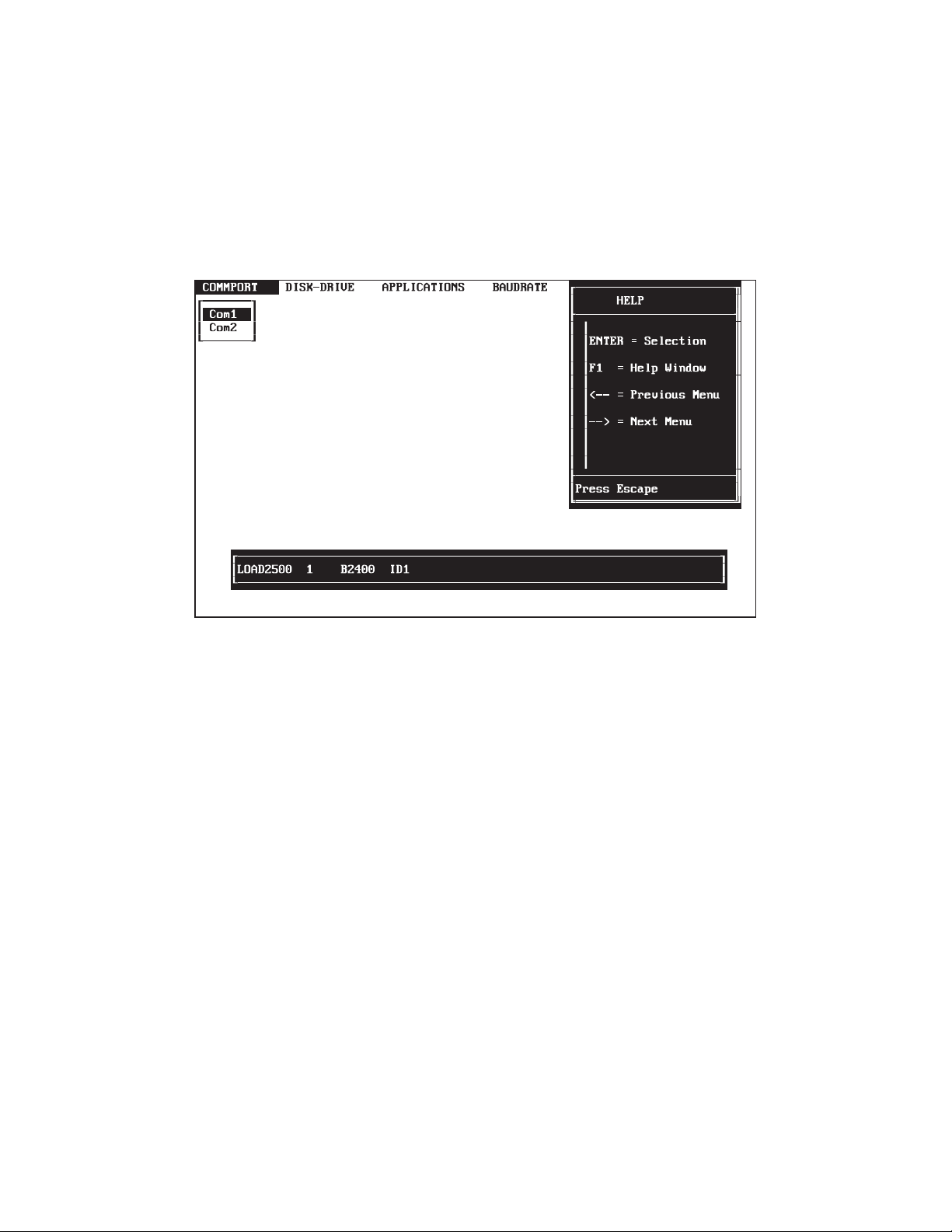
6. Press the F1 function key.
As indicated on the screen below, this causes a HELP screen to be overlaid
in a window at the upper right portion of the screen being viewed.
7. At this point, the user may select and highlight the desired choice on the
HELP screen with the arrow keys, press the ENTER key, or press the ESC
(escape) key to exit from the HELP screen.
By using this procedure, a HELP screen is available whenever the user needs to
refer to it.
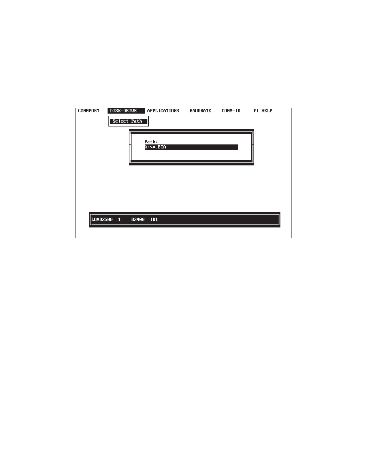
8. After removing the HELP screen, use the arrow keys to move from the
COMMPORT option window at the top of the screen to the DISK-DRIVE
option window, and press the ENTER key.
________________________________________________________________________________________________________________________________________
SECTIONSECTION 33
23
Page 38
____________________________________________________________________________________________________________ MODELMODEL 25002500
As indicated in the illustrated screen below, this causes a PATH screen to be
overlaid in a window in the right center portion of the screen being viewed. This
is a valid path if this IPL25 program is maintained on a diskette and not transferred
to the hard drive.
If the IPL25 program is transferred to the hard drive, the user will need to add a
directory\subdirectory to the program path.
9. At the PATH screen create a program path similar to
C:\"directory"\"subdirectory"\*.BTA
and press the ENTER key.
A reference window at the bottom of the screen will indicate whether the newly
created program path is a "Valid Path" or an "Invalid Path".
________________________________________________________________________________________________________________________________________
24
SECTIONSECTION 33
Page 39

MODELMODEL 2500_______________________________________________________2500_______________________________________________________
10. Once the reference window indicates a "Valid Path" has been created, use
the arrow keys to move from the DISK-DRIVE option window at the top of
the screen to the APPLICATIONS option window and press the ENTER key.
As indicated in the illustrated screen below, this causes a FILES screen to be
overlaid in a window in the center portion of the screen being viewed. One or more
files may be listed with the BTA extension, which means that they can be
downloaded to the Model 2500. Also, there may be two or more diskettes,
depending on the number of applications and their size.
11. At the FILES screen, select the desired application to be downloaded and
press the ENTER key. The selected application will be displayed in the path
number in the bottom reference screen.
12. Once the desired application has been selected and entered, use the arrow
keys to move from the APPLICATIONS option window at the top of the
screen to the BAUDRATE option window. Select the desired baud rate and
press the ENTER key.
________________________________________________________________________________________________________________________________________
SECTIONSECTION 33
25
Page 40

____________________________________________________________________________________________________________ MODELMODEL 25002500
If the Model 2500 has no configuration program, its default baud rate is normally
2400. If the downloaded application replaces a resident program, the baud rate
must match the slave baud rate on the Model 2500 receiving the application.
As indicated in the illustrated screen below, this causes a baud rate list to be
overlaid in a window beneath the BAUDRATE option window at the top of the
screen.
If the user selects a baud rate different than 2400, a "b" prefix, which is a code that
changes the baud rate in the Model 2500, will appear just before the baud rate
number in the reference screen. At this point, the user should press the ENTER
key.
13. Once the desired baud rate has been selected and entered, use the arrow keys
to move from the BAUDRATE option window at the top of the screen to the
COMMID option window and press the ENTER key.
________________________________________________________________________________________________________________________________________
26
SECTIONSECTION 33
Page 41

MODELMODEL 2500_______________________________________________________2500_______________________________________________________
As indicated in the screen below, this causes a COMMID number screen to be
overlaid in a window beneath the COMMID option window at the top of the
screen.
The default COMMID number is 1, but a communications identification number
from 1 through 247 may be assigned. However, if an active program is resident in
the user’s Model 2500, the number assigned must match the COMMID number as
indicated in the System Command Menu.
14. When changing the COMMID number, the user must type in the number
assigned and press the ENTER key.
The following rules apply when changing the COMMID number:
- Do not place a "0" in front of one or two digit numbers.
- Delete mistakes by using the delete function or by typing over the
error.
________________________________________________________________________________________________________________________________________
SECTIONSECTION 33
27
Page 42

____________________________________________________________________________________________________________ MODELMODEL 25002500
- Correct erroneously entered numbers by pressing the ENTER key
again and re-entering the number.
At this point, the user must check all entries in the reference window at the bottom
of the screen. If all entries are correct, the user is ready to download the application
to the Model 2500.
15. When all entries are correct, the user must press the ESC (escape) key twice
to return to the MAIN MENU.
16. If the MODEL 2500 is set up and ready, at the MAIN MENU use the arrow
keys to select and highlight the LOAD 2500 option and press the ENTER
key to load the application.
If a problem occurs, recheck the communications link, COMMPORT, COMMID,
etc., and the steps described above for loading the application.
17. When the downloading of the application is complete, use the arrow keys to
select and highlight the EXIT option and press the ENTER key to leave the
program.
________________________________________________________________________________________________________________________________________
28
SECTIONSECTION 33
Page 43

MODELMODEL 2500_______________________________________________________2500_______________________________________________________
LOAD 2500 - STAND-ALONE DOWNLOAD PROGRAM
A stand-alone utility program, LOAD2500, is provided on the DANIEL software
diskette to download configurations into the DANIEL INDUSTRIES MODEL
2500.
After the MODEL 2500 has been activated and the system prompt appears, the
LOAD2500 program is invoked by using the command line illustrated and
explained below.
Command line: LOAD2500 n cccccccc [ Byyyy IDzzz A ]
n Number of the computer communications port
cccccccc BTA file name of the configuration, with the possible
subdirectory location. The file extension is not entered.
Byyyy Optional entry to set the baud rate to yyyy. Valid baud rates are
300, 1200, 2400, 4800, and 9600. If the baud rate is omitted or
entered incorrectly in the command line, LOAD2500 defaults to
a 2400 baud rate.
IDzzz Optional entry to set Comm ID to zzz. Comm ID is valid from
1 to 247. If the Comm ID is omitted or entered incorrectly,
LOAD2500 defaults to 1.
A Optional entry required only for loading a configuration created
with Revision G of CONFIG25.
________________________________________________________________________________________________________________________________________
SECTIONSECTION 33
29
Page 44

____________________________________________________________________________________________________________ MODELMODEL 25002500
STAND-ALONE DOWNLOAD PROGRAM EXAMPLES
Following are several examples of the command line for the downloading of
LOAD2500 configurations:
- LOAD2500 1 D533011B B1200 ID12
This example illustrates the downloading of application number
D533011B through communications port 1, at a 1200 baud rate, and
sets the Comm ID to 12.
- LOAD2500 2 D533011B ID24
This example illustrates the downloading of application number
D533011B through communications port 2, at the default baud rate of
2400, and sets the Comm ID to 24.
- LOAD2500 1 C511009A B300
This example illustrates the downloading of application number
C511009A through communications port 1, at a 300 baud rate, and
sets the Comm ID to the default value of 1.
_________________________________________________________
NOTE! If all of the preceding steps have been properly
executed and the MODEL 2500 does not accept the
new program, make certain that the revision level of
the BASE25 EPROMs matches the revision level of the
Config25 program used to build the BTA file.
_________________________________________________________
________________________________________________________________________________________________________________________________________
30
SECTIONSECTION 33
Page 45

MODELMODEL 2500_______________________________________________________2500_______________________________________________________
The following table lists the CONFIG25 software releases that are supported and
the baseline used for execution. The following compatibility rules are imposed by
the download routine.
Compatible BASE25 Revisions
CONFIG25
Revision
K.2 12/86 yes no no no yes
L.7 6/87 no yes yes yes yes
L.8 10/87 no yes yes yes yes
N 2/88 no no no yes yes
5.nn 12/89 no no no yes yes
Release
Date
K.2 L.7 L.8 N 5.nn
________________________________________________________________________________________________________________________________________
SECTIONSECTION 33
31
Page 46

____________________________________________________________________________________________________________ MODELMODEL 25002500
SYSTEM READY
If the results of the automatic initializing sequence have been satisfactory, the
MODEL 2500 LCD screen gives a message similar to the following illustration,
which indicates that front-panel operation can begin.
53301510
13-JAN-89 08:34
Line 1 of the display (in this example, 53301510) is the designation for the
alphanumeric configuration that has been downloaded to the Model 2500. Line 2
gives the current date and time.
DATA ENTRY SECURITY
Data entry security is provided by:
- Three-position security switch
- Two-level password system consisting of a lower-level password and
a restricted-user password
The lower-level password provides for changing constants and variable values that
are not designated as limited-access variables. The restricted-user password
provides access for changing the limited-access variables. Functioning of the
passwords is controlled by the three-position security switch.
________________________________________________________________________________________________________________________________________
32
SECTIONSECTION 33
Page 47

MODELMODEL 2500_______________________________________________________2500_______________________________________________________
SECURITY SWITCH
A three-position security switch controls operator changes to variables in the
system through the front panel. The switch is located at the rear of CPU I/O
board.
The three selections provided by the switch are defined in the table below.
POSITION DEFINITION
DOWN Lower-level security password entry is not required to change
data. Restricted-user password entry may be required.
CENTER Password entry is allowed and required to change data.
UP Password entry is not allowed. Data cannot be changed at the
front panel of the instrument.
________________________________________________________________________________________________________________________________________
SECTIONSECTION 33
33
Page 48

____________________________________________________________________________________________________________ MODELMODEL 25002500
LOWER-LEVEL SECURITY PASSWORD
If the security switch, which is located at the rear of CPU I/O board, is in the
center position, an operator must enter the lower-level security password before
entering or changing variable values in the system. The lower-level security
password remains active for five minutes after the last key is pressed. The system
command "Unit Lock" disables the unit password and the password must be entered
again in order to change data.
When the instrument is downloaded, the default lower-level password is eight 1s,
(11111111). Installing a new, user-originated, lower-level password at the initial
startup of the MODEL 2500 system, is recommended.
________________________________________________________________________________________________________________________________________
34
SECTIONSECTION 33
Page 49

MODELMODEL 2500_______________________________________________________2500_______________________________________________________
RESTRICTED-USER PASSWORD
The restricted-user password provides an additional level of security for
user-specified, limited-access variables. The restricted-user password may not be
entered until the lower-level password is activated.
Until the restricted-user password is entered, limited-access variables can be
displayed, but cannot be changed, regardless of the state of the lower-level
password. After the restricted-user password is entered, limited-access variables
can be changed.
If the three-position security switch is in the center position, the restricted-user
password remains active for five minutes after the last key is pressed. In this
switch position, the system command "Unit Lock" disables the restricted-user
password and the lower-level password.
If the three-position security switch is in the up position, the restricted-user
password will not automatically time-out after five minutes, and must be disabled
using the "Unit Lock" command.
The factory-installed restricted-user password is "11111111". A new,
user-originated, restricted-user password should be entered at initial startup.
_________________________________________________________
CAUTION! Since neither the standard-unit password, nor the
restricted-user password can be retrieved after
being entered, a record of each should be kept in
a secure location for future reference. However,
the standard unit password may be over-written
if the security switch is in the down position.
_________________________________________________________
________________________________________________________________________________________________________________________________________
SECTIONSECTION 33
35
Page 50

____________________________________________________________________________________________________________ MODELMODEL 25002500
DATA ENTRY AT INITIAL STARTUP
Before a DANIEL INDUSTRIES MODEL 2500 INSTRUMENTATION SYSTEM
is placed in service, constants and variables for the application must be entered in
the microcomputer memory, or changed if this data differs from factory-installed
values. Data entry is made through the MODEL 2500 front panel keypad.
The following occurs when a MODEL 2500 system is configured for a specific
application:
- Default value for each constant and variable required for that
configuration is stored in the computer memory.
- Variables are stored in either a fixed or a dynamic mode, depending
on how the values are specified when the Model 2500 is initially
configured with CONFIG25.
- Variables will remain as configured until modified.
- All variables and constants are named and are available for display in
real time on the front panel.
- Calculation variables are displayed only if units for the variables are
assigned.
- Calculation variables can be changed manually only if units for the
variables were assigned the first time the variables were defined.
________________________________________________________________________________________________________________________________________
36
SECTIONSECTION 33
Page 51

MODELMODEL 2500_______________________________________________________2500_______________________________________________________
PROCEDURE OF DATA ENTRY AT INITIAL STARTUP
The procedural steps for entering data during initial startup of the DANIEL
INDUSTRIES MODEL 2500 INSTRUMENTATION SYSTEM are as follows:
1. Turn on the MODEL 2500 and ensure that the normal start-up message,
which is illustrated below, is displayed.
D513024A
13-JAN-89 08:34
2. Unlock the front panel for data entry by pressing the DOWN arrow on the
front panel keypad several times until the message "SYSTEM
COMMANDS" appears on the lower text line of the LCD screen display.
_________________________________________________________
NOTE! Continuously holding down the key, rather than
pressing it several times will cause the display to
scroll rapidly through the MAIN MENU and may
result in overshooting the SYSTEM COMMANDS
sub-menu. If this occurs, continue to press the
DOWN arrow one step at a time until the message
SYSTEM COMMANDS reappears.
_________________________________________________________
3. Press the ENTER key once.
4. Press the DOWN arrow one step at a time until the message "UNIT
PASSWORD" appears.
5. Pressing the ENTER key once.
________________________________________________________________________________________________________________________________________
SECTIONSECTION 33
37
Page 52

____________________________________________________________________________________________________________ MODELMODEL 25002500
6. Press the number 1 key 8 times, which will cause the default password,
"11111111" to appear on the LCD screen,
7. Press the ENTER key. This will cause the green LED on the front panel to
glow.
_________________________________________________________
NOTE! The password may be changed at this time by keying in
eight numbers on the front panel keypad. (The MODEL
2500 accepts prefixed zeros as discrete, which means the
instrument requires all eight digits of a number such as
00000004 in order to interpret the number 4 as the
password.) When the new password has been keyed in,
press the ENTER key. The keyboard now can be
unlocked for data entry only with the new password.
The password cannot be retrieved once entered, and
should be recorded in a secure location.
_________________________________________________________
8. Scroll to the desired sub-menu and lower sub-menu by pressing the arrow
keys.
9. Key in new or revised data, and enter the data by pressing the ENTER key.
_________________________________________________________
CAUTION! Changing values in the Model 2500 system may
activate alarms, which must be cleared before
placing the unit in service.
_________________________________________________________
10. Press the arrow keys when data entry is complete to find the lower sub-menu
UNIT LOCK located in the sub-menu SYSTEM COMMANDS.
________________________________________________________________________________________________________________________________________
38
SECTIONSECTION 33
Page 53

MODELMODEL 2500_______________________________________________________2500_______________________________________________________
11. Press the ENTER key when the message "UNIT LOCK" appears on the LCD
screen.
_________________________________________________________
NOTE! After approximately five minutes with no keyboard
activity, the MODEL 2500 automatically disables the
keyboard for data entry until the password is re-entered.
_________________________________________________________
________________________________________________________________________________________________________________________________________
SECTIONSECTION 33
39
Page 54

____________________________________________________________________________________________________________ MODELMODEL 25002500
TYPICAL START-UP DATA CHANGES
The following list represents data that is often changed from the factory-installed
default values at the initial start-up of a MODEL 2500 configured for a specific
application:
- Measured or hand-entered values of process variables
- Definitions of the metering arrangement, including:
- Flange or pipe-tap differential pressure transmitters
- Upstream or downstream static pressure transmitters
- Single or dual-range differential pressure transmitters
- Settings for zero (4 mA) and full-scale (20 mA) values (in engineering
units) of transmitter inputs
- Desired multipliers for readouts of flow rates and flow accumulators
- High and low alarm limits
- Calibration units for frequency-type densitometers
- Base values for temperature and pressure
- Barometric pressure for the measurement site
- Unit ID number for printout identification
- Time and date
- Contract hour and time period between printouts
________________________________________________________________________________________________________________________________________
40
SECTIONSECTION 33
Page 55

MODELMODEL 2500_______________________________________________________2500_______________________________________________________
TIME-OF-DAY CLOCK CHIP
DANIEL INDUSTRIES MODEL 2500 microcomputer units that have a
time-of-day clock chip will continue to provide the time even when the unit is
without power either because of a power failure or because the instrument is in
storage.
When the MODEL 2500 is in operation, the clock chip is updated several times a
day as follows:
- Approximately two-hour intervals
- Shortly after midnight each day
- Whenever the time of day is changed
The clock chip is additional and secondary to the time of day maintained by the
software clock, which is an integral part of the MODEL 2500 operating system.
________________________________________________________________________________________________________________________________________
SECTIONSECTION 33
41
Page 56

____________________________________________________________________________________________________________ MODELMODEL 25002500
This page intentionally left blank.
________________________________________________________________________________________________________________________________________
42
SECTIONSECTION 33
Page 57

MODELMODEL 2500_______________________________________________________2500_______________________________________________________
MENU SELECTION
The DANIEL INDUSTRIES MODEL 2500 INSTRUMENTATION SYSTEM
microcomputer enters, changes and displays operating commands and data by
making selections from various menus displayed on the LCD screen located on the
front panel of the instrument.
Individual menus, which are organized into groups of related data and functions,
are configured for each specific application, and only appear on the display screen
when required by the specific application.
________________________________________________________________________________________________________________________________________
SECTIONSECTION 44
43
Page 58

____________________________________________________________________________________________________________ MODELMODEL 25002500
MAIN MENU
The highest level menu in the MODEL 2500 is the MAIN MENU, which is
activated after the completion of diagnostic testing and when the "TIME and
DATE" message is displayed on the LCD screen.
Depending on the MODEL 2500 configuration, the MAIN MENU contains up to
11 sub-menus, each of which either provides a functional category for accessing
system data or for controlling the instrument.
________________________________________________________________________________________________________________________________________
44
SECTIONSECTION 44
Page 59

MODELMODEL 2500_______________________________________________________2500_______________________________________________________
SUB-MENUS
The MAIN MENU’s 12 possible sub-menus are listed below with those menus that
appear in all system configurations marked with an asterisk (*).
- INPUT CHANNELS
- OUTPUT CHANNELS
- ALARMS*
- OPERATOR ENTRY
- CALCULATIONS*
- REPORTS
- TABLES
- TUBE SWITCHING
- MODBUS MASTER
- SERIAL PORTS*
- ARCHIVE
- SYSTEM COMMANDS*
When required by an application, each sub-menu may have one or more lower
sub-menus that provides for specific data entry, or system control in the category
covered by that sub-menu.
The following flow-chart graphically illustrates how to enter and exit each of the
11 sub-menus, and refers the user to other diagrams, which are listed at the end of
this section, that illustrate the lower level sub-menus within the 11 main submenus.
________________________________________________________________________________________________________________________________________
SECTIONSECTION 44
45
Page 60

____________________________________________________________________________________________________________ MODELMODEL 25002500
The following is a detailed explanation of the MAIN MENU’s 12 sub-menus.
INPUT CHANNELS
The INPUT CHANNELS sub-menu, which is the first selection listed on the MAIN
MENU, has three lower level sub-menus. They are:
ANALOG INPUTS The ANALOG INPUTS lower level sub-menu
displays the variable names, values, units, alarm
limits, scaling factors, and default values of the
analog input channels.
STATUS INPUTS The STATUS INPUTS lower level sub-menu
provides for changing the states of status (discrete)
input channels, and for displaying the variable
names, states, and units.
PULSE INPUTS The PULSE INPUTS lower level sub-menu allows
the values of the pulse input channels to be
changed, and displays the channel variable names,
values, and units.
OUTPUT CHANNELS
The OUTPUT CHANNELS sub-menu, which is the second selection on the Main
menu, has two lower level sub-menus. They are:
ANALOG OUTPUTS The ANALOG OUTPUTS lower sub-menu
provides for changing the values of the analog
output channels and for displaying the variable
names, values, units, alarm limits, and scaling
factors of the channels.
________________________________________________________________________________________________________________________________________
46
SECTIONSECTION 44
Page 61

MODELMODEL 2500_______________________________________________________2500_______________________________________________________
CONTROL OUTPUTS The CONTROL OUTPUTS lower level sub-menu
provides for changing the values of the control
output channels and for displaying the variable
names, values, and units.
ALARMS
The ALARMS sub-menu, which is the third selection on the MAIN MENU, has
two lower sub-menus. They are:
UNACKED ALARMS The UNACKED (unacknowledged) ALARMS
lower level sub-menu displays all alarms that have
not been acknowledged by the operator.
CURRENT ALARMS The CURRENT ALARMS lower level sub-menu
displays currently active alarms.
OPERATOR ENTRY
The OPERATOR ENTRY sub-menu, which is the fourth sub-menu on the MAIN
MENU, has two lower sub-menus. They are:
NUMERIC ENTRIES The NUMERIC ENTRIES lower level sub-menu
allows the values of numeric operator entries to be
changed and displays the names, values, units, and
alarm limits of the entries. Typical numeric entries
for a MODEL 2500 configuration, which measures
orifice mass and volume of a liquid, are the
specific gravity of the liquid, the hour when daily
reports are printed, base temperature and pressure
for calculations, and pipe and orifice diameters.
________________________________________________________________________________________________________________________________________
SECTIONSECTION 44
47
Page 62

____________________________________________________________________________________________________________ MODELMODEL 25002500
SELECTION
ENTRIES The SELECTION ENTRIES lower level sub-menu
displays the name, units, and startup selection of
selection list operator entries, and allows for
changing the startup selections. For example, in a
MODEL 2500 configured to measure orifice mass
and volume, selection list operator entries are
typically the type and location of orifice taps.
Startup selections for tap type are pipe and flange.
Startup selections for tap location are upstream and
downstream.
CALCULATIONS
The CALCULATIONS sub-menu, which is the fifth sub-menu on the MAIN
MENU, has the names of individual calculation sheets as lower level sub-menus.
Individual calculation sheets provide programming instructions for data processing
by the MODEL 2500. Representative calculation sheets include those that:
- Perform initialization routines
- Process status inputs
- Process operator entries
- Process timer functions
- Perform flow rate, volume, and mass calculations
- Process report scheduling
REPORTS
The REPORTS sub-menu, which is the sixth sub-menu on the MAIN MENU, has
lower level sub-menus composed of each report produced by a MODEL 2500
configuration.
A complete report can be printed by pressing the ENTER key when the report
name is displayed on the front panel.
________________________________________________________________________________________________________________________________________
48
SECTIONSECTION 44
Page 63

MODELMODEL 2500_______________________________________________________2500_______________________________________________________
_________________________________________________________
NOTE! Applications in which report lengths are in excess of
one page require a printer with an 8k buffer capacity,
or the baud rate of the printer output signal must be
lowered to 300, and the RPTGAP lower level sub-menu
must be set to SPACES.
_________________________________________________________
TABLES
The TABLES sub-menu, which is the seventh sub-menu on the MAIN MENU, has
a lower level sub-menu for each data table defined in the configuration.
TUBE SWITCHING
The TUBE SWITCHING sub-menu, which is the eighth sub-menu on the MAIN
MENU, provides the following list of variables that define common switching
parameters for all tube sets and individual switching parameters for each tube in
a set.
Common switching parameters for all tube sets:
Time delay variable The time delay variable is a user-entered interval
that allows time for a valve to change position, and
for the position change to affect the differential
pressure across the tube set before the position of
the next valve in the set is changed. The default
value for this variable is 120 seconds.
Verify DP variable The verify DP variable enables or disables
automatic verification of the differential pressure
________________________________________________________________________________________________________________________________________
SECTIONSECTION 44
49
Page 64

____________________________________________________________________________________________________________ MODELMODEL 25002500
level after a valve position change is ordered by the
MODEL 2500. When the variable is OFF, no
verification is performed.
Verify level variable The verify level variable specifies the cutoff value
for differential pressure across a tube set to be used
in verifying a valve position change. The default
value of this variable is 2.
Control number
variable The control number (#) variable displays the
number of the tube assigned as the current control
tube.
Individual tube switching parameters are listed for the first tube in a set in the
following order and repeat in that same order for each subsequent tube. Tubes are
listed in the desired sequence for switching the valves.
DP name Differential pressure name is the analog input variable
with a value that represents the current differential
pressure transmitted.
Low Low differential pressure switchpoint (expressed in
engineering units) across a tube when the valve
controlling the tube is closed. The default value for this
variable is 2.
High High differential pressure switchpoint (expressed in
engineering units) across a tube when the valve
controlling the tube is opened. The default value for this
variable is 98.
State Operational status of the tube being displayed (i.e.,
enabled, disabled, fault). The default status of this
variable is "enabled".
________________________________________________________________________________________________________________________________________
50
SECTIONSECTION 44
Page 65

MODELMODEL 2500_______________________________________________________2500_______________________________________________________
Open Boolean variable that opens the valve when set
Close Boolean variable that closes the valve when set
MODBUS MASTER
The MODBUS MASTER sub-menu, which is the ninth sub-menu on the MAIN
MENU, has a lower level sub-menu for defining two remote units. The remote unit
definition sub-menu provides for identifying or changing the remote name ID, the
communications address and state variable, and the control option for each of the
two remote units.
Name Identifies the remote unit
Communications
Address Integer variable for the communications address of the
slave unit. If a communications address is not entered,
the default variable is zero. When the communications
address is zero, communications with the remote unit is
disabled.
State Integer variable that contains the current MODBUS
function code transmitted and received for the remote
unit. The state entry provides a means of monitoring the
activity between the master and remote units. Error
conditions are also visible by means of this variable.
Control Three options available here are:
IDLE Indicating no communications in progress
ACTIVE Indicating communications in progress
FAULT Indicating failure to communicate with a
slave unit
________________________________________________________________________________________________________________________________________
SECTIONSECTION 44
51
Page 66

____________________________________________________________________________________________________________ MODELMODEL 25002500
SERIAL PORTS
The SERIAL PORTS sub-menu, which is the tenth sub-menu on the MAIN
MENU, is categorized by, and divided into one-board units and two-board units.
One-board units have thirteen lower level sub-menus, which are COMMID
BAUD1, BAUD2, PORTUSE1, PORTUSE2, PARITY1, PARITY2, STOPBIT1,
STOPBIT2, PRTCLSLV, PRTCLMAS, RPTGAP, and COMMWAIT.
Two-board units have twenty lower level sub-menus, which are COMMID,
COMMID2, BAUD1, BAUD2, BAUD3, PORTUSE1, PORTUSE2, PORTUSE3,
PARITY1, PARITY2, PARITY3, STOPBIT1, STOPBIT2, STOPBIT3,
PRTCLSLV, PRTCLSLV2, PRTCLMAS, RPTGAP, COMMWAIT AND
COMMWAIT2.
_________________________________________________________
NOTE! Applications with reports exceeding one page require
that the printer has an 8k buffer capacity, or the baud
rate of the printer output signal is lowered to 300 with
the RPTGAP lower level sub-menu set to SPACES.
This note applies to BAUD1 and BAUD2 of the
SERIAL PORTS sub-menu for one-board units and
BAUD1, BAUD2, and BAUD3 of the SERIAL PORTS
sub-menu for two-board units.
_________________________________________________________
________________________________________________________________________________________________________________________________________
52
SECTIONSECTION 44
Page 67

MODELMODEL 2500_______________________________________________________2500_______________________________________________________
The SERIAL PORTS Lower Level Sub-Menus are as follows:
COMMID COMMID lower sub-menu provides a specific
communications address for the connected device. The
addresses allowed are 1-247 without zeros in front of the
one and two digit numbers. The default setting is 1.
COMMID2 (Two board units only) COMMID2 lower sub-menu
provides a specific communications address for the
connected device. The addresses allowed are 1-247
without zeros in front of the one and two digit numbers.
The default setting is 1.
BAUD1 BAUD1 lower level sub-menu provides for displaying or
changing the baud rate settings for serial port number 1.
The baud rate selections are 300, 1200, 2400, 4800, and
9600, with the default rate being 1200.
BAUD2 BAUD2 lower level sub-menu provides for displaying or
changing the baud rate settings for serial port number 2.
The baud rate selections are 300, 1200, 2400, 4800, and
9600, with the default rate being 2400.
BAUD3 (Two-board units only) BAUD3 lower level sub-menu
provides for displaying or changing the baud rate settings
for serial port number 3. The baud rate selections are
300, 1200, 2400, 4800, and 9600, with the default rate
being 1200.
________________________________________________________________________________________________________________________________________
SECTIONSECTION 44
53
Page 68

____________________________________________________________________________________________________________ MODELMODEL 25002500
_________________________________________________________
NOTE! When changing serial port assignments using
PORTUSE1, PORTUSE2, and PORTUSE3, selecting
remote front panel (REMOTEFP) for a serial port,
which is not actually connected to a remote front panel,
results in loss of control of the unit. Control is regained
by simultaneously pressing the zero, decimal, and
minus keys on the unit’s front panel keypad.
Downloading the Model 2500 can only be done through the
SLAVE port, not SLAVE #2. If 2 SLAVE ports are required
with one SLAVE port assigned to each board, a two-board unit
is required.
_________________________________________________________
PORTUSE1 PORTUSE1 lower level sub-menu provides for displaying
or changing the way serial port number 1 is being used
(NONE, REPORTS, SLAVE, MASTER, REMOTEFP,
USERCOMM), with the default being REPORTS.
PORTUSE2 PORTUSE2 lower level sub-menu provides for displaying
or changing the way serial port number 2 is being used
(NONE, REPORTS, SLAVE, MASTER, REMOTEFP,
USERCOMM), with the default being SLAVE.
PORTUSE3 PORTUSE3 lower level sub-menu provides for displaying
or changing the way serial port number 3 is being used
on a two-board unit (NONE, REPORTS, SLAVE,
MASTER, REMOTEFP, USERCOMM), with the default
being NONE.
________________________________________________________________________________________________________________________________________
54
SECTIONSECTION 44
Page 69

MODELMODEL 2500_______________________________________________________2500_______________________________________________________
PARITY1 PARITY1 lower level sub-menu provides for displaying
or changing the parity of serial port number 1 (EVEN,
ODD, NONE), with the default parity being EVEN.
PARITY2 PARITY2 lower level sub-menu provides for displaying
or changing the parity of serial port number 2 (EVEN,
ODD, NONE), with the default parity being EVEN.
PARITY3 PARITY3 lower level sub-menu provides for displaying
or changing the parity.
STOPBIT1 STOPBIT1 lower level sub-menu provides for displaying
or changing the number of stopbits transmitted from
serial port number 1 (1, 1 1/2, 2), with the default stopbit
setting being 1.
STOPBIT2 STOPBIT2 lower level sub-menu provides for displaying
or changing the number of stopbits transmitted from
serial port number 2 (1, 1 1/2, 2), with the default stopbit
setting being 1.
STOPBIT3 (Two-board units only) STOPBIT3 lower level sub-menu
provides for displaying or changing the number of
stopbits transmitted from serial port number 3 (1, 1 1/2,
2), with the default stopbit setting being 1.
PRTCLSLV PRTCLSLV lower level sub-menu provides for displaying
or changing the type of communications used by any one
of the serial ports, which is defined in the portuse section
as a SLAVE (MODASCII or MODRTU), with the default
type being MODASCII.
PRTCLSLV2 (Two-board units only) PRTCLSLV2 provides the same
function as PRTCLSLV for two-board units.
________________________________________________________________________________________________________________________________________
SECTIONSECTION 44
55
Page 70

____________________________________________________________________________________________________________ MODELMODEL 25002500
PRTCLMAS PRTCLMAS lower level sub-menu provides for
displaying or changing the type of communications used
by any one of the serial ports, which is defined in the
portuse section as a MASTER (MODASCII or
MODRTU), with the default type being MODASCII.
RPTGAP RPTGAP lower level sub-menu provides for selecting
SPACES, FORMFEED, or ANSIHOME with SPACES,
with the latter being the default setting, and also with
providing spaces between report printouts, providing,
through FORMFEED, a formfeed command between
reports, and providing, through ANSIHOME, printing
reports with special control characters to permit reports to
be displayed on an ANSI-type terminal.
COMMWAIT COMMWAIT provides a delay (in tens of milliseconds)
between receiving a message and transmitting a response.
The COMMWAIT default value is 20 (200 milliseconds).
COMMWAIT2 (Two-board units only) COMMWAIT2 provides the same
function as COMMWAIT for two-board units.
ARCHIVE
The ARCHIVE sub-menu, which is the eleventh sub-menu on the MAIN MENU,
provides for data storage and retrieval similar to a file.
SYSTEM COMMANDS
The SYSTEM COMMANDS sub-menu, which is the twelfth sub-menu on the
MAIN MENU, has nine lower level sub-menus. They are:
DATE/TIME
PARAMETERS Sets the date and time
________________________________________________________________________________________________________________________________________
56
SECTIONSECTION 44
Page 71

MODELMODEL 2500_______________________________________________________2500_______________________________________________________
UNIT PASSWORD Allows entering and/or changing the eight-digit
lower-level password that unlocks the front panel
to change data other than limited access variables.
Default is "11111111".
RESTRICTED PSWD Allows entering and/or changing the eight-digit
restricted-user password that permits a user to
change limited access variables. Default is
"11111111".
UNIT LOCK Allows locking the keyboard after an authorized
user has entered or changed data in the MODEL
2500.
UNIT ID NUMBER Provides a four-character identification number that
appears on all reports. Default is "0".
COMM PASSWORD Provides a security handshake for communications.
Default is "11111111".
COMMID NUMBER Provides a communications address that can be any
number from 1 through 247. Default is "1".
LOGGER Provides for either calculation-initiated or
automatic printing of current alarm conditions and
operator changes.
________________________________________________________________________________________________________________________________________
SECTIONSECTION 44
57
Page 72

____________________________________________________________________________________________________________ MODELMODEL 25002500
Logs are printed on the serial port selected for REPORTS. Five selection
entries are provided for the LOGGER command. They are shown in the chart
below:
Selection 2500 Operation
NO LOG No logging is performed.
ALRM SET Alarm set logging is performed.
ALRM S/R Alarm set and reset logging is performed.
OPCHANGE Operator change logging is performed.
ALRM&OPR ALRM S/R and OPCHANGE selections are
combined.
Log formats are illustrated below:
ALARM SET Logging:
------------------------------------------------------------------------------------------------------------
53301510 UNIT:0000 ALARM SET LOGGER JAN 13 1987 09:14
TEMP LO-LO LIMIT = -2 -3.
------------------------------------------------------------------------------------------------------------
ALARM RESET Logging:
------------------------------------------------------------------------------------------------------------
53301510 UNIT:0000 ALARM RESET LOGGER JAN 13 1987 09:14
TEMP LO-LO LIMIT = -2 103.
------------------------------------------------------------------------------------------------------------
________________________________________________________________________________________________________________________________________
58
SECTIONSECTION 44
Page 73

MODELMODEL 2500_______________________________________________________2500_______________________________________________________
OPERATOR CHANGE Logging:
------------------------------------------------------------------------------------------------------------
53301510 UNIT:0000 OPERATOR CHANGE LOGGER JAN 13 1987 09:14
TEMP FIXED VALUE 103.
------------------------------------------------------------------------------------------------------------
CURRENT ALARMS Logging:
------------------------------------------------------------------------------------------------------------
53301510 UNIT:0000 CURRENT ALARMS LOGGER JAN 13 1987 09:14
TEMP LO-LO LIMIT = -2 -3.
TEMP LO LIMIT = -2 -3.
------------------------------------------------------------------------------------------------------------
If a log is requested and no alarms or operator changes are present, the
normal log header is printed, followed by the message: "The list is empty".
CHECKSUM Detects changes made to configurations provided
by DANIEL INDUSTRIES, INC. and is generated
from fixed data tables in the configuration
following a download. When changes are made to
a configuration and downloaded, the checksum
changes, even if the configuration appears to
remain the same.
________________________________________________________________________________________________________________________________________
SECTIONSECTION 44
59
Page 74

____________________________________________________________________________________________________________ MODELMODEL 25002500
MENU DISPLAY AND SELECTION PROCEDURE
Menu selections are selected and displayed on the DANIEL INDUSTRIES MODEL
2500 by pressing the UP and DOWN, and the EXIT and ENTER keys.
A detailed explanation of the functioning of each of these four keys follows:
ENTER Key
- Enters data and selects entry options displayed on the MODEL
2500 front panel LCD screen.
- Prints a line report when the name of the report is displayed on
the LCD screen.
- Provides access to selections on the menu levels.
For example, if the TIME and DATE message is displayed,
which indicates that the MAIN MENU is currently active,
pressing any key one time displays the first selection of the
MAIN MENU. This first selection is INPUT CHANNELS, if
INPUT CHANNELS is active in the configuration, which is
then displayed on the LCD screen.
Pressing the ENTER key again displays the first selection of the
INPUT CHANNELS sub-menu. This first selection is ANALOG
INPUTS, if ANALOG INPUTS is active in the configuration,
and which is then displayed on the LCD screen.
________________________________________________________________________________________________________________________________________
60
SECTIONSECTION 44
Page 75

MODELMODEL 2500_______________________________________________________2500_______________________________________________________
EXIT Key
- Moves the display to the next higher level menu.
For example, if INPUT CHANNELS and ANALOG INPUTS
are active in the configuration, and if the message "ANALOG
INPUTS" is displayed on the bottom line of LCD screen, this
indicates that the current menu level is the INPUT
CHANNELS.
Pressing the EXIT key one time displays the message "INPUT
CHANNELS" on the bottom line, indicating the current menu
level is now the MAIN MENU.
UP ARROW Key
- Steps the display up through the selections on the active menu.
For example, if the MAIN MENU is active and the last
selection, SYSTEM COMMANDS is displayed, pressing the UP
ARROW key one time displays the next higher selection on the
MAIN MENU, and the message "ARCHIVES" appears, if
ARCHIVES is active in the configuration.
Pressing the UP ARROW key another time will display the next
higher MAIN MENU selection, SERIAL PORTS.
Holding down the UP ARROW key rather than pressing it one
step at a time causes the display to continue moving up through
the menu selections rather than displaying one selection at a
time. If INPUT CHANNELS is active in the configuration, and
if the UP ARROW key is pressed when the first selection,
INPUT CHANNELS, is displayed, the display does not loop to
the last selection, but continues to read INPUT CHANNELS.
________________________________________________________________________________________________________________________________________
SECTIONSECTION 44
61
Page 76

____________________________________________________________________________________________________________ MODELMODEL 25002500
DOWN ARROW Key
- Displays through the selections of the menu level that is active.
For example, if INPUT CHANNELS and OUTPUT
CHANNELS are both active in the configuration, and if the
MAIN MENU is active with one of the menu selections, such
as INPUT CHANNELS, being displayed, pressing the DOWN
ARROW key one time displays the next selection on the MAIN
MENU, and the message "OUTPUT CHANNELS" appears.
Pressing the DOWN ARROW key again will display the next
MAIN MENU selection, ALARMS. Holding down the DOWN
ARROW key rather than pressing it one step at a time causes
the display to continue moving down through the menu rather
than displaying one selection at a time. If the DOWN ARROW
key is pressed when the last selection, SYSTEM COMMANDS,
is displayed, the display will loop back to the first selection,
INPUT CHANNELS, if INPUT CHANNELS is active in the
configuration.
________________________________________________________________________________________________________________________________________
62
SECTIONSECTION 44
Page 77

MODELMODEL 2500_______________________________________________________2500_______________________________________________________
MENU FLOW CHART DIAGRAMS
The following flow chart diagrams illustrate the following:
- Relationship of the MAIN MENU’s 11 sub-menus
- Relationship of these 11 sub-menus to the lower level sub-menus
________________________________________________________________________________________________________________________________________
SECTIONSECTION 44
63
Page 78

____________________________________________________________________________________________________________ MODELMODEL 25002500
11 SUB-MENUS CHART
________________________________________________________________________________________________________________________________________
64
SECTIONSECTION 44
Page 79

MODELMODEL 2500_______________________________________________________2500_______________________________________________________
INPUT CHANNELS CHART
________________________________________________________________________________________________________________________________________
SECTIONSECTION 44
65
Page 80
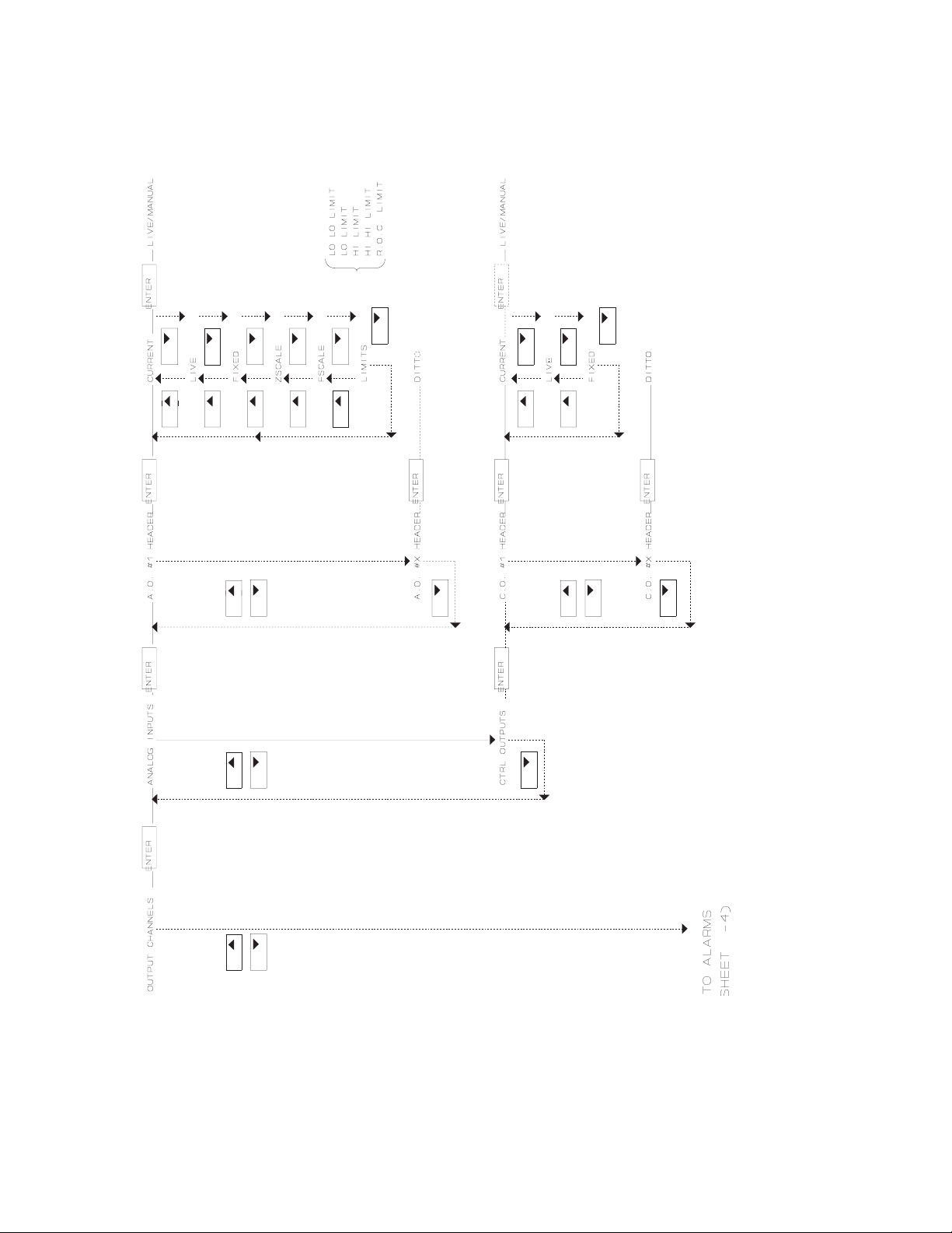
____________________________________________________________________________________________________________ MODELMODEL 25002500
OUTPUT CHANNELS CHART
________________________________________________________________________________________________________________________________________
66
SECTIONSECTION 44
Page 81

MODELMODEL 2500_______________________________________________________2500_______________________________________________________
ALARMS CHART
________________________________________________________________________________________________________________________________________
SECTIONSECTION 44
67
Page 82
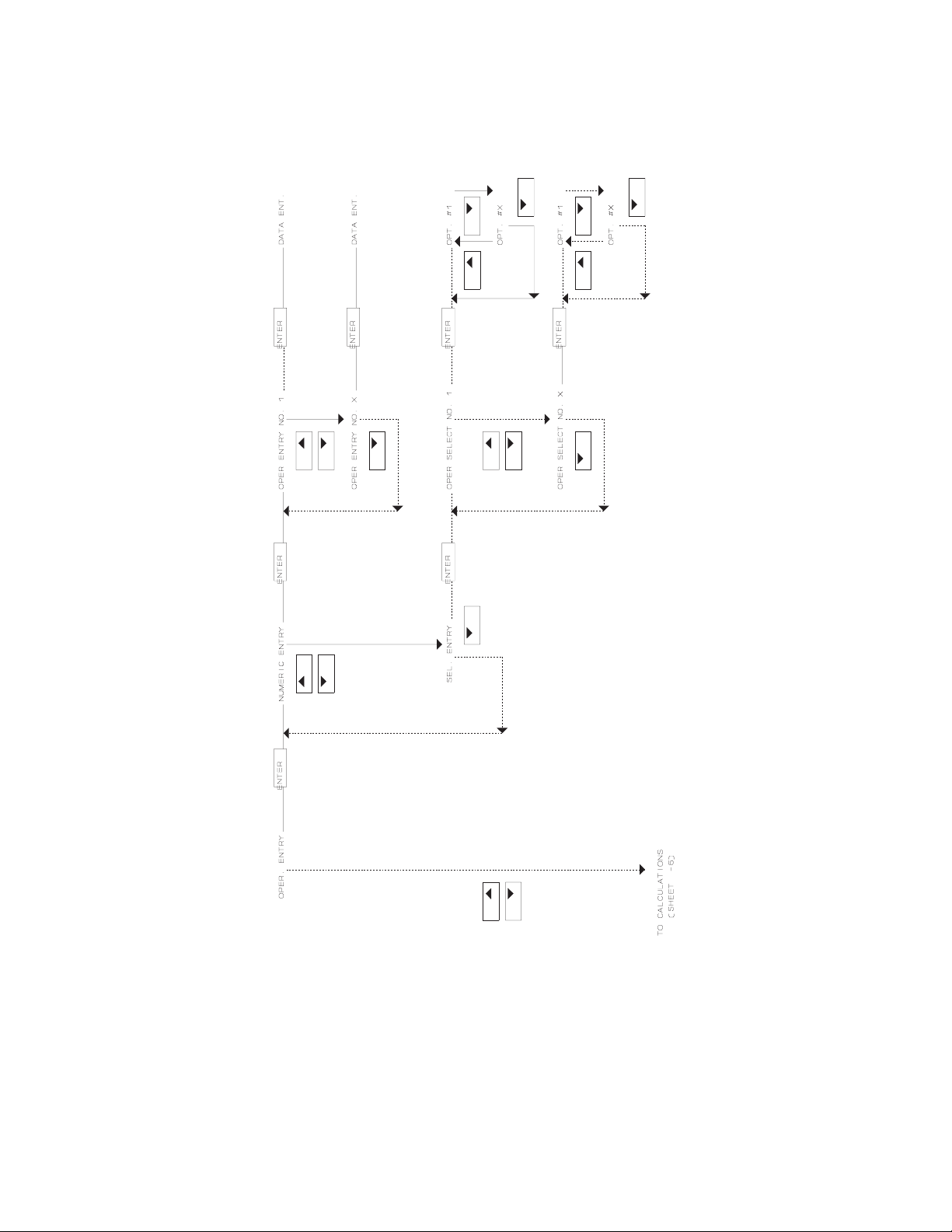
____________________________________________________________________________________________________________ MODELMODEL 25002500
OPERATOR ENTRY CHART
________________________________________________________________________________________________________________________________________
68
SECTIONSECTION 44
Page 83
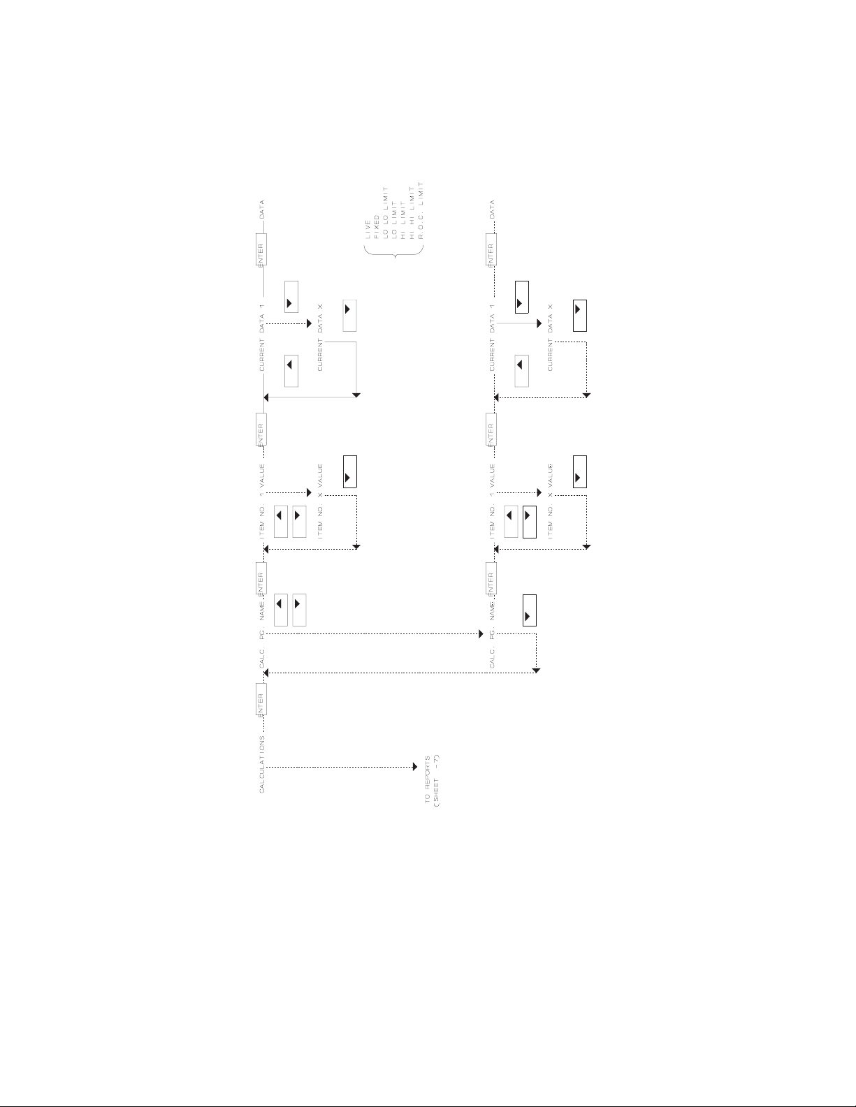
MODELMODEL 2500_______________________________________________________2500_______________________________________________________
CALCULATIONS CHART
________________________________________________________________________________________________________________________________________
SECTIONSECTION 44
69
Page 84
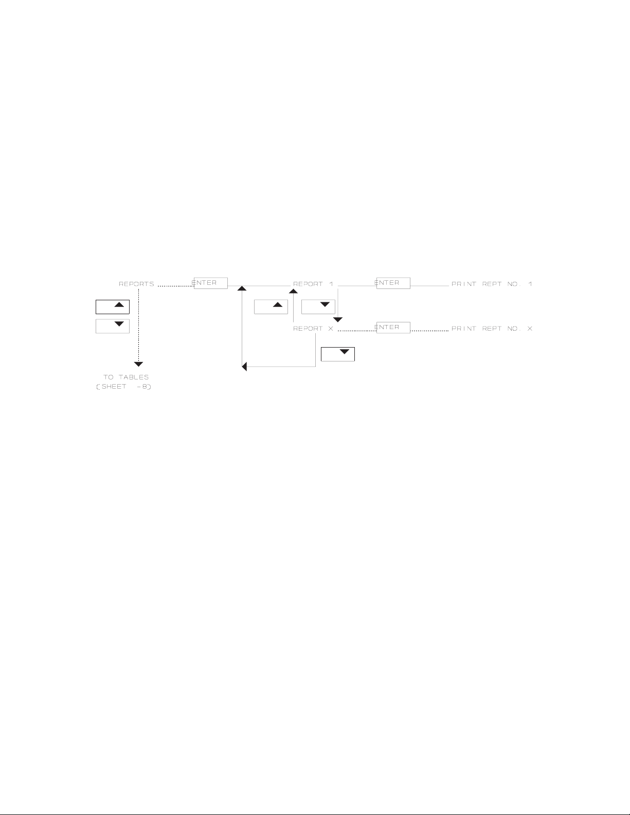
____________________________________________________________________________________________________________ MODELMODEL 25002500
REPORTS CHART
________________________________________________________________________________________________________________________________________
70
SECTIONSECTION 44
Page 85
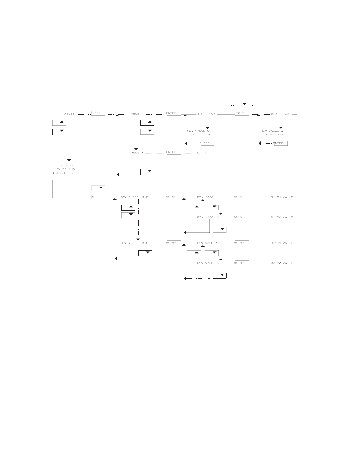
MODELMODEL 2500_______________________________________________________2500_______________________________________________________
TABLES CHART
________________________________________________________________________________________________________________________________________
SECTIONSECTION 44
71
Page 86

____________________________________________________________________________________________________________ MODELMODEL 25002500
TUBE SWITCHING CHART
________________________________________________________________________________________________________________________________________
72
SECTIONSECTION 44
Page 87
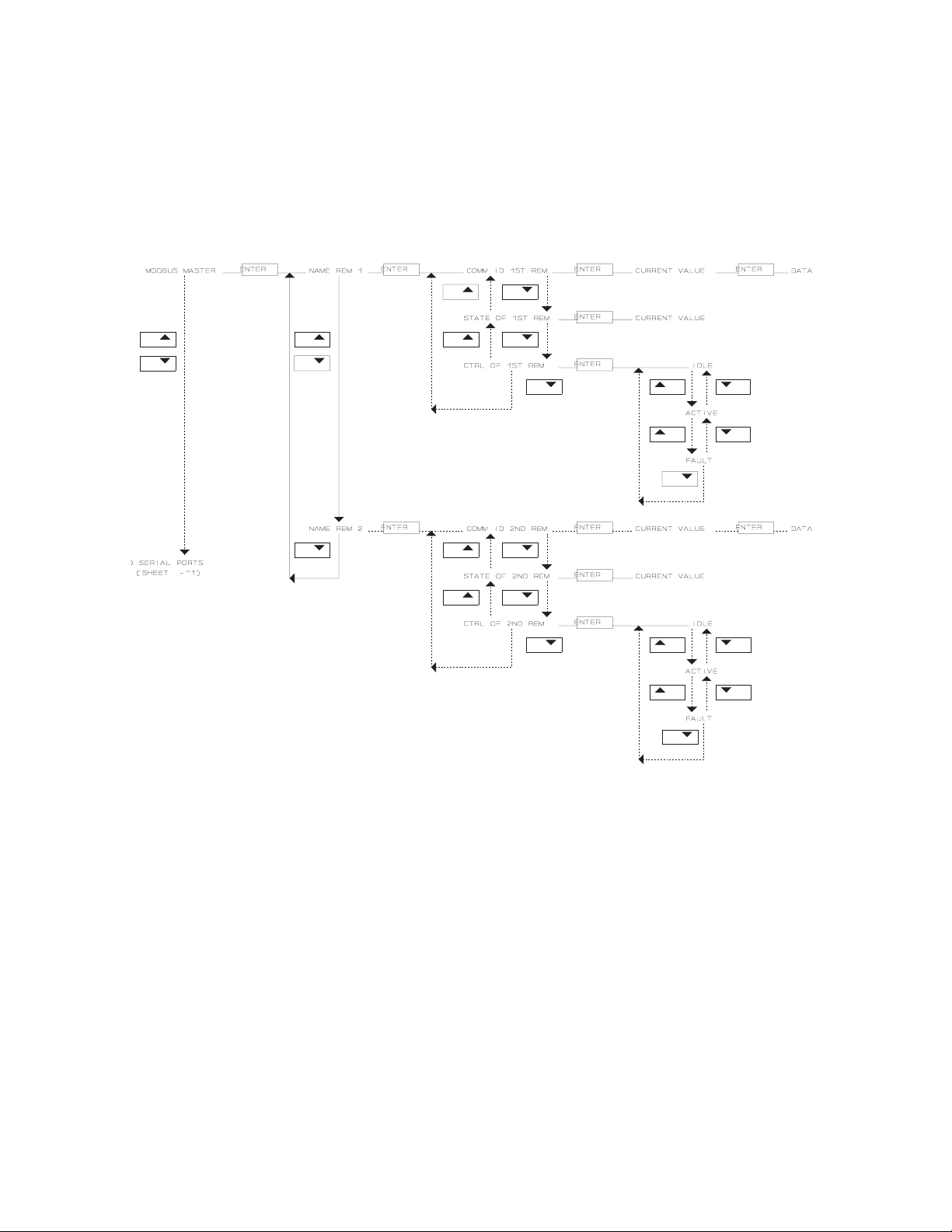
MODELMODEL 2500_______________________________________________________2500_______________________________________________________
MODBUS MASTER CHART
________________________________________________________________________________________________________________________________________
SECTIONSECTION 44
73
Page 88
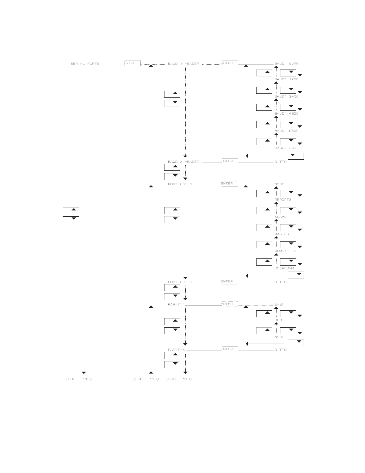
____________________________________________________________________________________________________________ MODELMODEL 25002500
SERIAL PORTS CHART A
________________________________________________________________________________________________________________________________________
74
SECTIONSECTION 44
Page 89

MODELMODEL 2500_______________________________________________________2500_______________________________________________________
SERIAL PORTS CHART B
________________________________________________________________________________________________________________________________________
SECTIONSECTION 44
75
Page 90

____________________________________________________________________________________________________________ MODELMODEL 25002500
ARCHIVE CHART
________________________________________________________________________________________________________________________________________
76
SECTIONSECTION 44
Page 91

MODELMODEL 2500_______________________________________________________2500_______________________________________________________
SYSTEM COMMANDS CHART
________________________________________________________________________________________________________________________________________
SECTIONSECTION 44
77
Page 92

____________________________________________________________________________________________________________ MODELMODEL 25002500
This page intentionally left blank.
________________________________________________________________________________________________________________________________________
78
SECTIONSECTION 44
Page 93

MODELMODEL 2500_______________________________________________________2500_______________________________________________________
DATA DISPLAY
The constants and variables for the DANIEL INDUSTRIES MODEL 2500
INSTRUMENTATION SYSTEM are displayed on the front panel LCD screen and
include the name, status, current value, and engineering units for constants and
variable. These constants and variables will all be explained in detail in the
following section.
________________________________________________________________________________________________________________________________________
SECTIONSECTION 55
79
Page 94

____________________________________________________________________________________________________________ MODELMODEL 25002500
CONSTANT/VARIABLE NAME
The name of the constant or variable can be from 1 to 8 characters in length, and
in the illustrations in the following sub-section entitled TYPE OF DISPLAY, the
names are represented by the characters "nnnnnnnn".
________________________________________________________________________________________________________________________________________
80
SECTIONSECTION 55
Page 95

MODELMODEL 2500_______________________________________________________2500_______________________________________________________
CONSTANT/VARIABLE STATUS
The status of the constant or variable can be from 1 to 8 characters in length, and
in the illustrations in the following sub-section entitled TYPE OF DISPLAY, the
statuses are represented by the characters "sssssss". Definitions of typical status
display abbreviations are shown in the following table.
Status Display
Abbreviation
MANUAL Value used in the calculations is
currently the FIXED value.*
blank Value used in the calculations is
currently the LIVE value.*
LIVE Current value from transmitter input*
FIXED Operator-entered over-ride value*
Z SCALE Zero-scale value
F SCALE Full-scale value
LO LO Lo Lo alarm limit
LO Lo alarm limit
HI Hi alarm limit
Definition
HI HI Hi Hi alarm limit
RATE Rate of change limit
* Detailed explanations of the status abbreviations MANUAL, blank, LIVE,
and FIXED are provided in Section 6, under the sub-section entitled,
CHANGING THE STATUS OF A VARIABLE.
________________________________________________________________________________________________________________________________________
SECTIONSECTION 55
81
Page 96

____________________________________________________________________________________________________________ MODELMODEL 25002500
CONSTANT/VARIABLE VALUE
The value of the constant or variable can be from 1 to 11 characters in length, and
in the illustrations in the following sub-section entitled TYPE OF DISPLAY, the
current values are represented by the characters "vvvvvvvvvvv".
________________________________________________________________________________________________________________________________________
82
SECTIONSECTION 55
Page 97

MODELMODEL 2500_______________________________________________________2500_______________________________________________________
CONSTANT/VARIABLE UNITS
The engineering units of the constant or variable can be from 1 to 4 characters in
length, and in the illustrations in the following sub-section entitled TYPE OF
DISPLAY, the units are represented by the characters "uuuu".
________________________________________________________________________________________________________________________________________
SECTIONSECTION 55
83
Page 98

____________________________________________________________________________________________________________ MODELMODEL 25002500
TYPE OF DISPLAY
The manner in which constants and variables are displayed on the MODEL 2500
LCD screen indicates whether the data shown is for display only, or if data entry
is also allowed. If the variable/constant name (nnnnnnnn) and status (sssssss) are
on line 1 of the LCD screen, as shown in the following illustration, then data can
be entered on the keypad.
nnnnnnnn sssssss
vvvvvvvvvvv uuuu
If the variable/constant name (nnnnnnnn) and status (sssssss) are on line 2 of the
LCD screen, as shown in the following illustration, then data is for display only
and no data can be entered on the keypad.
vvvvvvvvvvv uuuu
nnnnnnnn sssssss
The following illustration, which shows a display that can be changed by operator
entry:
- Gives a current value of 1740.2 for the variable PLINE1.
- Lists the engineering units in pounds per square inch, gauge (PSIG).
- Leaves the status field blank, which indicates that the value used for
PLINE1 in calculations is the live value.
________________________________________________________________________________________________________________________________________
84
SECTIONSECTION 55
Page 99

MODELMODEL 2500_______________________________________________________2500_______________________________________________________
Changing and entering data is explained in Section 6, along with an
explanation of live value in the sub-section entitled, CHANGING THE
STATUS OF A VARIABLE.
PLINE1
1740.2 PSGI
The following illustration, which contains the same constant and variable data as
displayed in the preceding illustration, but with the display lines reversed (or
inverted), cannot be changed by operator entry, and is for display only.
1740.2 PSGI
PLINE1
________________________________________________________________________________________________________________________________________
SECTIONSECTION 55
85
Page 100

____________________________________________________________________________________________________________ MODELMODEL 25002500
ALARMS FOR VARIABLES AND CONSTANTS
The following illustration gives the general format for the display of alarms for
variables and constants:
- Line 1 (nnnnnnnn) represents the name of the variable or constant
which can be from 1 to 8 characters in length.
- Line 2 (xxxxxxxxxxxxxxxx) represents the alarm message, which can
be from 1 to 16 characters in length.
nnnnnnnn
xxxxxxxxxxxxxxxx
Typical alarm messages are:
- SYSTEM ALARM
- RATE LIMIT
- HI-HI LIMIT
- HI LIMIT
- LO LIMIT
- LO-LO LIMIT
- USER ALARM
The following illustration shows an example of an alarm display for a variable:
- O I L H I H I is the name of the variable alarm (high-high oil level):
- HI-HI LIMIT isthealarm message indicating the oil level is
above the high-high alarm limit.
OILHIHI
HI-HI LIMIT
________________________________________________________________________________________________________________________________________
86
SECTIONSECTION 55
 Loading...