

Page 1
TP5000 Si Range
Electronic 5/2 day programmable room thermostat
Mains, Battery and RF versions
®
Certification Mark
GB
Installation and User Instructions
Page 2

GB
Index
Index
Installation Instructions 3-14
Product Speci cation 3
Installation 4
Cable Access and Wiring 5-8
Installer Advanced Programming Options 8-14
User Instructions 15-31
What is a Programmable Room Thermostat 15
Preset programmes 16-17
Setting Date and Time 18-19
Changing Preset Programmes 19-22
User overrides 22-25
Advanced User Programming Options 25-28
Overview of Installer Selectable Features 29-30
Setting References 31
2
Page 3

Installation Instructions
Please Note:
This product should only be installed by a quali ed electrician
or competent heating installer and should be in accordance
with the current edition of the IEEE wiring regulations.
Product Speci cation
Thermostat features TP5000 Si TP5000-RF Si TP5000M Si TP5000M 24 Si
GB
Power supply 2 x AA/MN1500/LR
alkaline cells
Memory back-up Retained for life of product
Temperature Range
Sensing
Factory set calendar
clock
Switching action of
output relay
Transmission frequency
(RF models)
Transmission range
(RF models)
Remote sensor inputs
(A models only)
3(1)A,
10-230V
Can be set by installer for remote temperature sensor,
limit sensor, window contact or telephone activated
Automatic summer/winter time change
N/A 3(1)A, 10-230V, Type 1B
N/A 433.92MHz N/A N/A
N/A 30m max. N/A N/A
switch contacts
230V, ±15%,
50Hz
5-30°C
24V, ±15%,
50Hz
Installation Instructions
Dimensions (mm) 110 wide, 88 high, 28 deep
Design standard EN60730-2-9 (EN300220 for RF)
Rated impulse voltage 2.5kV
Ball hardness test 75°C
Control pollution
situation
Temperature accuracy ±1°C
Time accuracy ±1 minute per month
Important note RF products: Ensure that there are no large metal objects, such as boiler cases
or other large appliances, in line of sight between the transmitter and receiver as these will
prevent communication between thermostat and receiver.
Degree 2
3
Page 4
GB
Installation Instructions
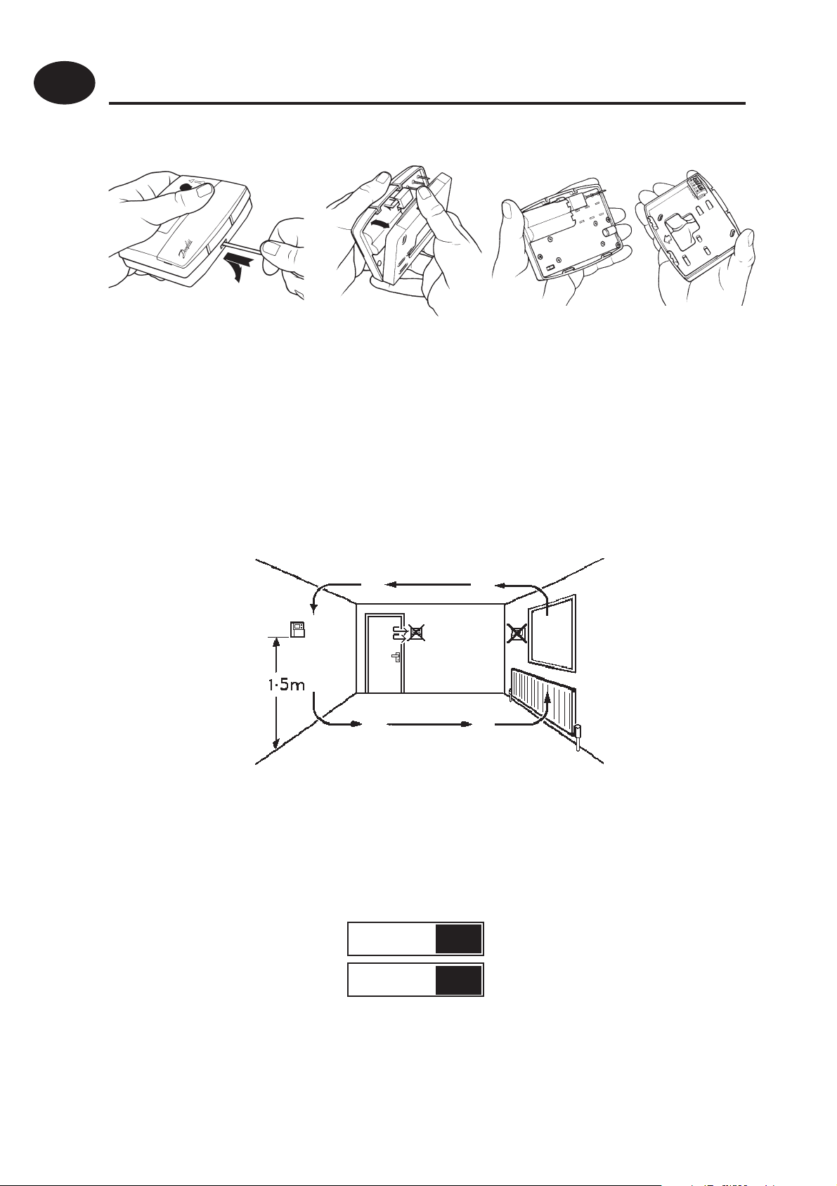
Installation
First, remove the wallplate from the back of the unit.
From the top left hand corner of the wallplate, there must be
clearances of at least 15mm to the right, 15mm to the left, 30mm
above and 100mm below in order to mount the plug-in module.
Thermostat and Remote Room Sensor:
Fix at a height of approximately 1.5m from the oor, away from
draughts or heat sources such as radiators, open res or direct
sunlight.
Prior to mounting the unit the 2 DIL switches on the rear of the
unit have to be moved to the required position. The factory
presets are shown below.
Sw. No.
OFF
ON
Keyboard disabled
1
2
4
Reset disabled Reset enabled
Keyboard enabled
Page 5
Cable Access
Battery Installation
When installing the batteries in the TP5000 Si and TP5000 Si RF please
GB
ensure that the correct polarity is observed as per the markings on the
inside of the battery compartment.
IMPORTANT: After installing the batteries press and release the
RESET button to start the unit. The display may appear blank until
this is done. Once the button is released the display will appear. All
date, time, programming and override settings are maintained for
the life of the product.
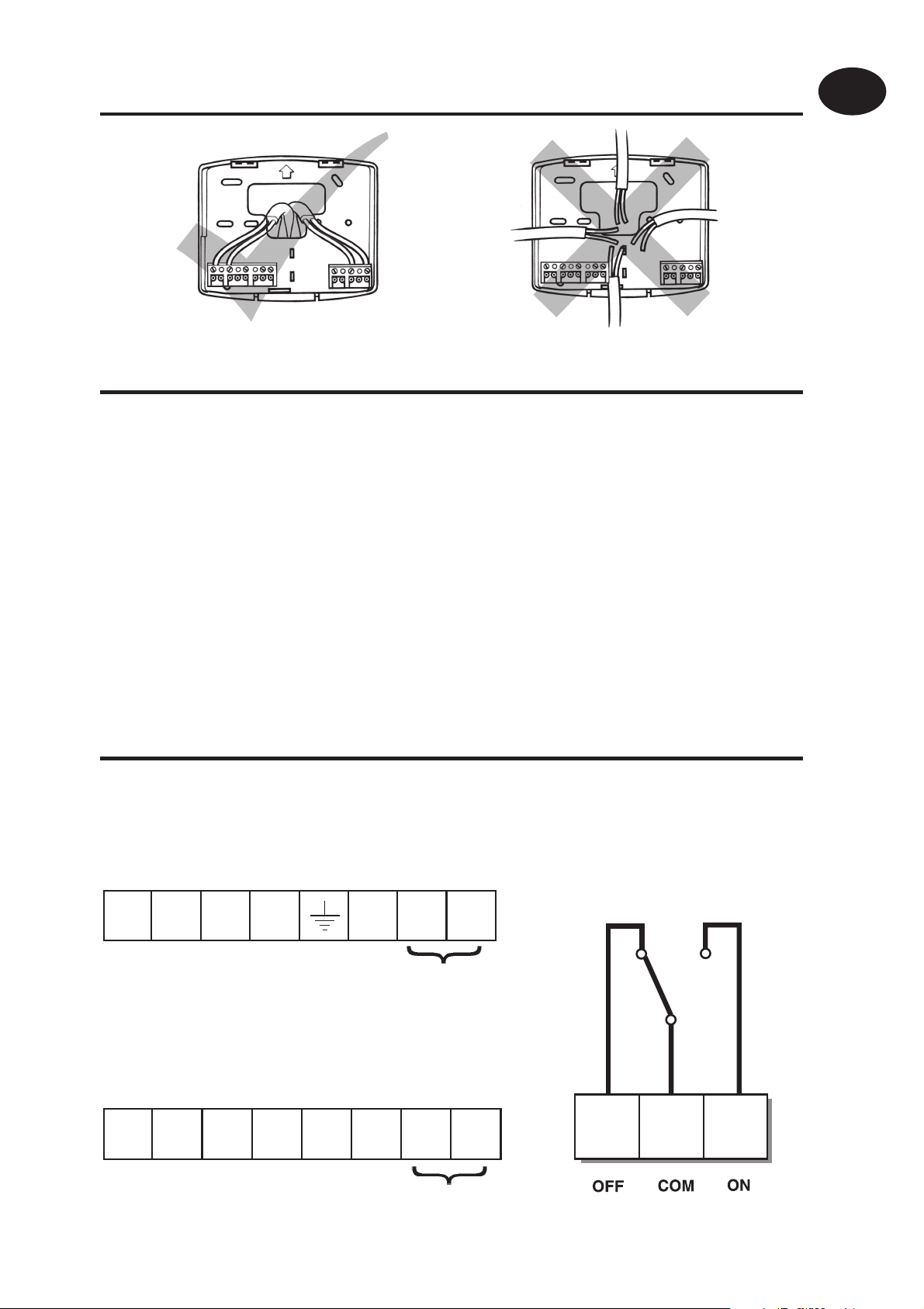
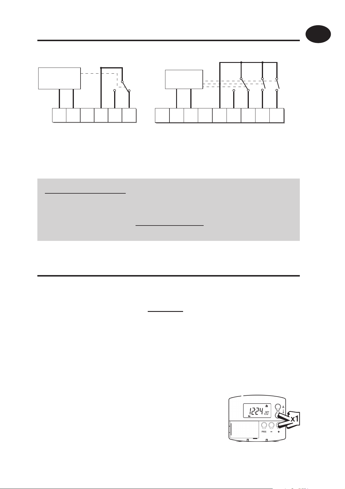
Wiring
Power Supply Connections
M 230V Models
Output Connections,
all hard wired models
Installation Instructions
N
M 24V Models
ADE
0V
L
B
24V
C
DE
Remote Sensor
(A version only)
Remote Sensor
(A version only)
1
2
3
5
Page 6
GB
/
/
Installation Instructions
Some existing thermostats will have a Neutral and/or Earth wire connected. These
are not required by the battery powered versions of the TP5000 Si and must NOT be
connected to any battery powered TP5000 Si terminals. Instead they should be made
!
electrically safe and coiled in the recess at the back of the TP5000 Si.
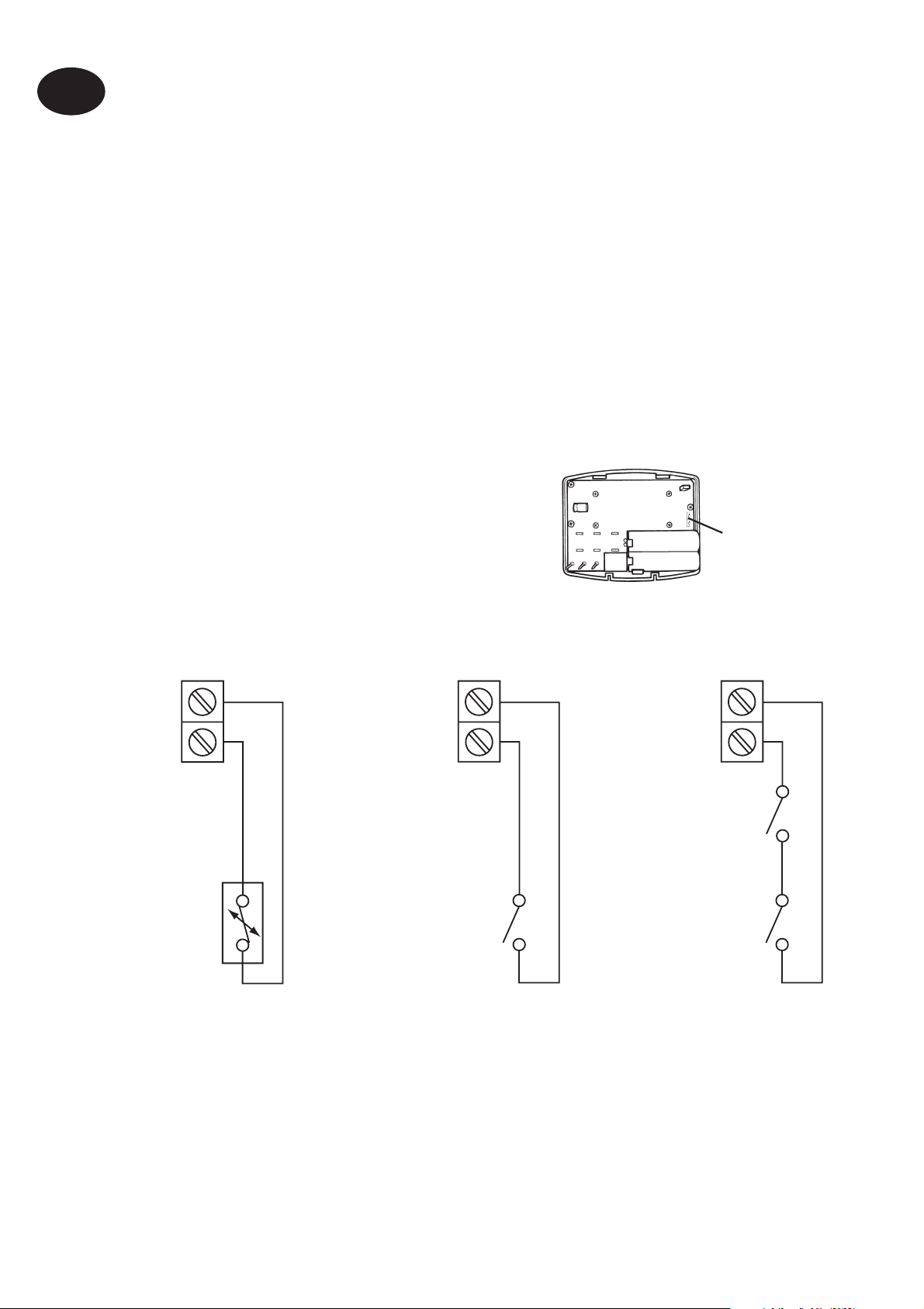
Models with remote sensor inputs
The TP5000A Si, TP5000A-RF Si and TP5000MA Si incorporate an input
which can be used to connect one of the following:
1) remote room temperature sensor (sold as accessory).
2) limit sensor, for example, oor temperature sensor (sold as
accessory).
3) window contacts, card reader contacts or teleswitch contacts.
See Installer Advanced Programming Options for set-up instructions.
Models with remote sensor inputs
Terminal block for remote control/
sensing is located on the circuit board
above the battery compartment.
S1/D
S2/E
S1/D
S2/E
Window or
teleswitch
contact
(NO or NC)
D
E
Remote
control
connections
Battery powered
verions
S1/D
S2/E
Window
contact (NC)
Teleswitch
contact (NC)
Con gured for
remote room
sensor or limit
sensor
Con gured for
window contact or
other contact such
as teleswitch
Con gured for
window contact
and other contact
such as teleswitch
Note:
Battery powered versions use S1 and S2.
Mains powered versions use D and E.
6
Page 7
RX Receiver Wiring (RF models only)
GB
RX1
ELECTRONICS
N
L
12
COM
3
ZONE
1 ON
4
ZONE
1 OFF
A
RX2 & RX3
ELECTRONICS
C1
B
L
N
345
2
COM
ZONE
1 ON
ZONE
1 OFF
ZONE
2 ON
6
ZONE
3 ON
1) For mains voltage operated systems link terminal 2 to mains live supply.
2) Power supply to unit must not be switched by timeswitch.
IMPORTANT
To ensure that the factory programmes are set and the microcomputer is operating correctly it is essential that you press and
TERMINAL 6
RX3 ONLY
Installation Instructions
hold the RESET button before you begin any commissioning or
programming.
Commissioning (RF models only)
If the thermostat and the receiver have been supplied together in
a combined pack, the units have been paired in the factory and no
commissioning is required (RX1 only).
To make the RX receiver learn the thermostat’s signal, follow steps 1-5
below.
Step 1
TP5000-RF Si - Reset the unit by pressing the recessed reset button.
Step 2
Press and hold V and + buttons for 3 seconds
(TP5000 RF Si now transmits unique signal
continuously for 3 minutes).
7
Page 8

GB
Installation Instructions
Step 3
RX1 - Press and hold buttons PROG and CH1 for 3
seconds until green light ashes once.
Step 4
RX2 (if applicable)
Stat 1 - perform steps 1-3 and 5.
Stat 2 -perform steps 1-2 and then press PROG and CH2 on RX2.
RX3 (if applicable)
Stat 1 - perform steps 1-3 and 5.
Stat 2 - perform steps 1-2 and then press PROG and CH2 on RX3 then
step 5.
Stat 3 - perform steps 1-2 and then press PROG and CH3 on RX3.
Step 5
TP5000Si-RF - Press V or Λ to select temperature - the unit will revert
back to operating mode.
Installer advanced
programming options
TP5000 Si incorporates a number of advanced features which can be
set by the user. These are accessed via a User Advanced Programming
Mode, please refer to User Advanced Programming in the user
instructions for details (see page 25).
Installer advanced programming options
TP5000 Si incorporates an additional number of advanced features
which can be set by the installer to improve the operating e ciency of
the system and where required, to change the user functionality of the
product. These are accessed via an Installer Advanced Programming
Mode. These settings are optional and need only be made if there is a
demand for the enhanced functions.
8
Page 9
Service Interval Timer
Instructions on how to access this feature are available from our
customer support desk. Please note these are only issued to boni- de
heating installers.
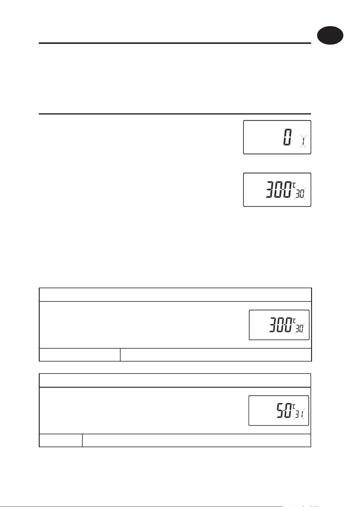
Entering Installer Advanced Programming Mode
To access the Installer Advanced Programming
Mode follow the steps below:
GB
a) Press and hold
enter User Advanced Programming, the display
will change to gure opposite.
b) Press and hold
to enter Installer Advanced Programming, the
display will change to gure opposite.
c) Use + and - keys to scroll backwards and forwards between options
then
on the right hand of the display indicates the number of the selected
option. The large characters display the option value selected.
d) To return to RUN, press and hold PROG until the display returns to
previous RUN mde.
Option 30 - Set upper limit of temperature range
This allows the upper limit of the thermostat setting
range to be electronically limited. Press + until
V and Λ keys to change the option settings. The ashing digit
V and PROG for 3 seconds to
V, Λ and PROG for 5 seconds
Installation Instructions
Option 30 is displayed, use V and Λ to select required
setting.
Setting 40 - 5°C (Factory setting is 30°C)
Option 31 - Set lower limit of temperature range
This allows the lower limit of the thermostat setting
range to be electronically limited. Press + until
Option 31 is displayed, use V and Λ to select required
setting.
Setting 5 - 40°C (Factory setting is 5°C)
9
Page 10
GB
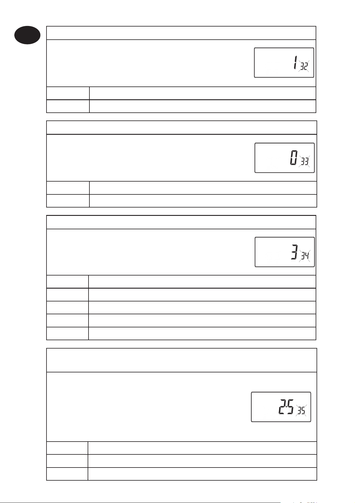
Option 32 - Enable O at lower limit
This enables an OFF function to be selected if a set
point below the lower limit is selected. Press + until
Option 32 is displayed, use
setting.
Setting 0 Disabled
Setting 1 Enabled (factory setting)
Option 33 - Enable On at upper limit
This enables an ON function to be selected if a set
point above the upper limit is selected. Press + until
Option 33 is displayed, use
setting.
Installation Instructions
Setting 0 Disabled (factory setting)
Setting 1 Enabled
Option 34 - Select On/O or Chrono-proportional
This allows the thermostat to be set to run in On/O
V and Λ to select required
V and Λ to select required
mode or for a chrono-proportional cycle rate to be
selected. Press + until Option 34 is displayed, use V
and Λ to select required setting.
0 On/O
3 3 cycles per hour
6 6 cycles per hour (factory setting)
9 9 cycles per hour
12 12 cycles per hour
Option 35 - Set integration time (Option 34 set to 3, 6, 9 or 12)
(seek advice prior to adjusting)
This adjusts the integration time of the PI algorithm
to increase control accuracy. It is only active if
option 34 has been set to Chrono 3, 6, 9 or 12.
It should only be adjusted after seeking advice
10
from the manufacturer. Press + until Option 35 is
displayed, use
2.5 Integration time set to 2.5% (factory setting)
5 Integration time set to 5%
10 Integration time set to 10%
V and Λ to select required setting.
Page 11

Option 36 - Set temperature override rule
This establishes the degree of temperature override
available to the user. Press + until Option 36 is
GB
displayed, use
Setting 0 No limit (factory setting)
Setting 1 Limited to ±2°C
Setting 2 No override allowed
Option 37 - Set time duration of override rule
(Option 36 set to 1 or 2)
This establishes the duration of a temperature
override available to the user. Press + until Option 37
is displayed, use V and Λ to select required setting.
Setting 0 Next event (factory setting)
Setting 1 1 hour
Setting 2 2 hours
Setting 3 3 hours
Setting 4 4 hours
V and Λ to select required setting.
Installation Instructions
Option 38 - Relay state on low battery detect
(battery products only)
This establishes the position that the relay is driven to
when the unit shuts down due to low battery state.
Press + until Option 38 is displayed, use
select required setting.
Setting 0 Relay parked with output OFF (factory setting)
Setting 1 Relay parked with output ON
Option 40 - Number of Events per Day
This sets the thermostat to operate with either 2, 4 or
6 switching events per day or to run it in stat mode.
Press + until option 40 is displayed, use Λ or V to
select required setting.
1 Stat mode
V and Λ to
2 Two switching events per day
4 Four switching events per day (Factory setting)
6 Six switching events per day
11
Page 12

GB
Installation Instructions
Option 41 - Operating Mode (5/2 day or 24 hour)
This sets the thermostat to operate using either
5/2 day or 24 hour mode. Press + until option 41 is
displayed, use Λ or V to select required setting.
5-2 5/2 day (Factory setting)
24 24 hour
Option 70 - Keyboard disable rules
This establishes the degree of functionality of the
keyboard available to the user. It is only active if DIL
switch 1 is set to “Disabled”. Press + until Option 70 is
displayed, use V and Λ to select required setting.
Setting 0 Normal lock: Programming functions locked (factory setting)
Setting 1 Full lock: All keys are disabled
Option 71 - Random start rules (24V/230 Volt models only)
This enables a random start on power-up following a
power cut to reduce load on the electrical network.
Random delay is in the range of 2 - 90 seconds. Press
+ until Option 71 is displayed, use V and Λ to select
required setting.
Setting 0 Disabled (factory setting)
Setting 1 Enabled
Option 72 - Owner site reference number
This enables multi-site owners to store a site reference
number in the thermostat. Press + until Option 72 is
displayed, use V and Λ to select required setting.
Setting Any value between 00 and 99 can be set
Factory setting is 00
12
Option 73 - Owner thermostat reference number
This enables site owners to store a thermostat reference
number in the thermostat. Press + until Option 73 is
displayed, use V and Λ to select required setting.
Setting Any value between 000 and 999 can be set
Factory setting is 000
Page 13

Option 74 - Date format for calendar clock
This allows date format to be chosen. Press +
until Option 74 is displayed, use V and Λ to select
required setting.
Setting 0 European format (dd/mm/yy), (Factory setting)
Setting 1 North American format (mm/dd/yy)
Option 81 - Thermostat calibration bias
This allows the thermostat calibration to be biased
by up to ±1.5°C. Press + until Option 81 is displayed,
use V and Λ to select required setting.
Setting Any value between ±1.5 in 0.5°C steps (Factory setting is 0°C)
Option 90 - De ne remote sensor type, “A” models only
This allows type of remote sensor input type to be
GB
Installation Instructions
de ned. Press + until Option 90 is displayed, use V
and Λ to select required setting.
Setting 0 No remote sensor tted (Factory setting)
Setting 1 Remote room or duct sensor tted, internal sensor disabled,
Setting 2 Remote limit sensor tted, refer to option 93 to de ne set-
point
Setting 3 Con gured as digital input for window, card reader or
teleswitch, refer to option 94 to de ne o/c or s/c.
Option 93 - Set limit sensor set-point, “A” models only,
(option 90 set to 2)
This allows the thermostat limit sensor to be set,
typical application is oor heating. Press + until
Option 93 is displayed, use V and Λ to select
required setting. If the temperature sensed by
the limit sensor exceeds the limit setting the
output will be turned o until the temperature
has dropped by 2°C. “F10” will ash in the display
while the output is disabled.
Setting Any value between 20 - 50°C (Factory setting is 27°C)
13
Page 14

GB
Installation Instructions
Option 94 - Con gure digital input switch type, “A” models only,
(option 90 set to 3)
This allows switch type of digital input to be
con gured. Press + until Option 94 is displayed,
use V and Λ to select required setting.
Setting 0 Contacts NC, open circuit contact to force unit into
thermostat mode, short circuit contacts to return to normal
operation
Setting 1 Contacts NO, short circuit contacts to force unit into
thermostat mode, open circuit contacts to return to normal
operation (Factory setting)
14
Page 15

What is a programmable room thermostat?
... an explanation for householders
A programmable room thermostat is both a programmer and a room thermostat. A
programmer allows you to set ‘On’ and ‘O ’ time periods to suit your own lifestyle. A
room thermostat works by sensing the air temperature, switching on the heating when
the air temperature falls below the thermostat setting, and switching it o once this set
temperature has been reached.
So, a programmable room thermostat lets you choose what times you want the heating
to be on, and what temperature it should reach while it is on. It will allow you to select
di erent temperatures in your home at di erent times of the day (and days of the week)
to meet your particular needs.
Turning a programmable room thermostat to a higher setting will not make the room
heat up any faster. How quickly the room heats up depends on the design of the heating
system, for example, the size of boiler and radiators.
Neither does the setting a ect how quickly the room cools down. Turning a
programmable room thermostat to a lower setting will result in the room being
controlled at a lower temperature, and saves energy.
The way to set and use your programmable room thermostat is to nd the lowest
temperature settings that you are comfortable with at the di erent times you have
chosen, and then leave it alone to do its job. The best way to do this is to set low
temperatures rst, say 18°C, and then turn them up by one degree each day until you
are comfortable with the temperatures. You won’t have to adjust the thermostat further.
Any adjustments above these settings will waste energy and cost you more money.
If your heating system is a boiler with radiators, there will usually be only one
programmable room thermostat to control the whole house. But you can have di erent
temperatures in individual rooms by installing thermostatic radiator valves (TRVs) on
individual radiators. If you don’t have TRVs, you should choose a temperature that is
reasonable for the whole house. If you do have TRVs, you can choose a slightly higher
setting to make sure that even the coldest room is comfortable, then prevent any
overheating in other rooms by adjusting the TRVs.
The time on the programmer must be correct. Some types have to be adjusted in spring
and autumn at the changes between Greenwich Mean Time and British Summer Time.
You may be able to temporarily adjust the heating programme, for example, ‘Override’,
‘Advance’ or ‘Boost’. These are explained in the manufacturer’s instructions.
Programmable room thermostats need a free ow of air to sense the temperature, so
they must not be covered by curtains or blocked by furniture. Nearby electric res,
televisions, wall or table lamps may prevent the thermostat from working properly.
GB
User Instructions
15
Page 16

GB
User Instructions
User Instructions
An introduction to your
programmable room thermostat
Your programmable room thermostat allows you to programme
di erent temperatures at di erent time periods. You can programme
one set of times and temperatures for week days with a di erent
set of temperatures for weekend days, this is referred to as 5/2 day
operation.
The thermostat can also be set up by your installer to provide one set
of times and temperatures that are repeated each day of the week. This
is referred to as 24 hour operation.
The thermostat can also be set by you to provide two di erent
programming blocks which can then be assigned to any day of the
week, this is referred to as A/B programme operation.
All thermostats can be set by your installer to provide up 2, 4 or 6 time
and temperature settings each day.
All thermostats feature useful overrides, including a programmable
frost setting.
Your thermostat has some advanced features which the installer will
set-up if they are required. There are also a number of advanced features
which can be set up by you. These advanced settings alter the way that
your thermostat operates, some also a ect the programming functions
and the user overrides. Please read the User Advanced Programming
instructions before programming the unit (see page 25).
Preset programmes
Your TP5000 Si comes ready programmed with a set of operating times
and temperatures which suit most people. Please remember that some
of the options available will depend on how the installer has set up the
unit.
16
Page 17

Weekdays (Mon-Fri) Weekend (Sat-Sun)
Event Time Temp. °C Event Time Temp. °C
1 06:30 20 1 07:30 20
2 08:30 15 2 09:30 20
3 11:30 20 3 11:30 20
4 13:30 15 4 13:30 20
5 16:30 21 5 16:30 21
6 22:30 15 6 22:30 15
GB
Note: these are also times for
Block “A” programmes
Note: If set up for 4 events per day, events 3 & 4 are skipped. If set up for
2 events per day, events 2, 3, 4 & 5 are skipped. In both cases the events
are re-numbered.
Note: these are also times for
Block “B” programmes
Before you start
Open the ap on the front of the programmer and
press the RESET button with a non-metallic object
until the display goes blank. This will ensure that
the micro-computer in the product is operating
correctly.
RESET
User Instructions
Customising the display
For the sake of clarity, the instructions assume that the display setting
uses a 24 hour clock, °C and that days of the week are shown as text.
All of these settings can be personalised after the thermostat has been
programmed, see pages 22 - 24.
Setting the correct date and time
Your TP5000 Si incorporates a real time clock with calendar function that
automatically changes time in both Spring and Autumn. The time and
date is set in the factory for the UK time zone, and does not normally
require adjustment. If you live in another time zone refer to “Time zone
o set” on page 26. However, should it be found necessary to adjust
time or date for any other reason refer to the following instructions.
17
Page 18

GB
User Instructions
Setting the date
Press and hold Λ and PROG for 3 seconds, to display
date in dd/mm/yy format.
The YEAR number will ash, use Λ or V to correct
the year.
Use - or + to move to MONTH, then use Λ or V to
correct month.
Use - or + to move to DATE in month, then use Λ or
V to correct day in month.
If you attempt to select an invalid date the unit software will reject it
and apply the nearest valid date. It is recommended that date is set in
the order, yy/mm/dd.
Setting the correct time
After setting the date press PROG to display the
time. The time display will ash on and o .
Use the + and - buttons to set the correct
time (press and hold to change in 10 min.
increments).
Setting the correct day
The day of the week is set automatically. Press
PROG to return to normal operation (RUN).
18
Page 19

Accepting the preset programmes
If you are happy with the preset times shown in the table on page
17you need take no further action.
Changing the preset programmes
Before you change the preset programmes
Your installer will have set the unit to operate in one of the following
modes:
5/2 day - one set of programmes for weekdays and another for
weekends (page 19-20).
24 hr - one set of programmes for the whole of the week (page 20).
GB
User Instructions
Alternatively
A/B - The unit can also be set by you to provide two programme
blocks, either of which can be applied to di erent days of the week.
If this is required refer to page 21 for instructions on how to turn on
this feature.
Please Note
The unit must be programmed in sequence, event times cannot be
set out of sequence.
If you want to leave a preset time as it is, simply press PROG to
move to the next setting.
If you want to return the unit to RUN, press PROG and hold until the
display returns to the previous RUN mode. Alternatively leave alone
and the unit will automatically return to RUN after 2 minutes.
Your installer will have set your unit to programme 6, 4 or 2 events
per day. This will determine the number of events per day that you
are able to programme.
Changing the preset programmes in 5/2 day mode
For Weekdays
a) Press PROG until the rst preset time and
temperature (Event 1 Days MON, TUE, WED,
THU, FRI) appears in display.
19
Page 20

GB
User Instructions
b) Use the + and - buttons to adjust the TIME (press and hold to
change in 10 minute increments).
c) Use the Λ and V buttons to adjust the required TEMPERATURE.
d) Press PROG to move to the next preset time
and temperature (Event 2).
e) Repeat steps b, c, & d to programme the
remaining weekday events.
For Weekends
Press PROG until the rst preset time and
temperature (Event 1 Days SAT, SUN) appears in
display.
Repeat steps b, c, & d above to programme the remaining weekend
events.
Changing the preset programmes in 24 hour mode
a) Press PROG until the rst preset time and
temperature (Event 1 for all days of the week)
appears in display.
b) Use the + and - buttons to adjust the TIME (press and hold to
change in 10 min increments).
c) Use the Λ and V buttons to adjust the required TEMPERATURE.
d) Press PROG to move to the next preset time
and temperature (Event 2).
e) Repeat steps b, c, & d to programme the
remaining events.
20
Page 21

Changing preset programmes for AB programming
(Installer setting must be in 5/2 day mode)
Press and hold PROG and V for 3 seconds. The
display will change to the gure opposite. This
will take you into User Advanced Programming
option 1.
Use Λ and V keys to enable or disable the function
(1=enabled, 0=disabled).
Press PROG for 5 seconds until the display returns
to previous RUN mode.
Press PROG once, the display will change to show
the default days assigned to programme “A” (days
MON, TUE, WED, THU, FRI).
GB
User Instructions
Use the + and - keys to scroll forwards or backwards
through the days of the week.
To deselect a day press V, (for example TUE). To
select a day press Λ (for example SUN).
Any deselected days are automatically assigned to programme “B”.
Programming “A” programme days and events
a) Press PROG until the rst preset time and
temperature (Event 1 for Programme A)
appears in display.
b) Use the + and - buttons to adjust the TIME
(press and hold to change in 10 minute increments).
c) Use the Λ and V buttons to adjust the required TEMPERATURE.
d) Press PROG to move to the next preset time and temperature
(Event 2).
e) Repeat steps b, c, & d to programme the remaining events.
21
Page 22

GB
User Instructions
Programming “B” programme days and events
a) Press PROG until the rst preset time and
temperature (Event 1 for Programme B)
appears in the display.
b) Use the + and - buttons to adjust the TIME (press and hold to
change in 10 minute increments).
c) Use the Λ and V buttons to adjust the required TEMPERATURE.
d) Press PROG to move to the next preset time and temperature
(Event 2).
e) Repeat steps b, c, & d to programme the remaining events.
Running the programme
Press PROG to return to previous RUN mode.
The heating will now follow the times and
temperatures programmed.
User Overrides
Altering the display to show time or temperature
Press + and - together to
change between settings.
Temporarily alter current programmed temperature
Press Λ or V until required temperature is displayed. Please note that
your installer may have restricted both upper and lower temperature
settings and the temperature override limits.
22
Page 23

This override will automatically be cancelled at the beginning of the
next programmed event. Please note that your installer may have
restricted the duration of the override to something other than next
event. In this case the override arrow will ash to indicate a timed
override is active during the next event
To change day of week legends from numbers to text
Press Λ and - together to toggle between day numbers and text.
To change time display between 12 hour and 24
hour clock
Press Λ and + together to toggle between 12 and 24 hour clock.
GB
User Instructions
To change between °C and °F scaling
Press V and - together to toggle between °C and °F temperature
scaling.
Thermostat mode
a) A constant temperature of between 5-30°C can be selected if
required. This can provide frost protection for periods away from
home, it can also be used to provide untimed higher temperatures
if, for example, a family member is sick.
b) Press Λ and V together to enter thermostat mode. The default
setting is 5°C, but this can be reprogrammed, see User Advanced
Programming, step 10, (page 27).
c) A frost protection symbol (snow ake in a
shield) will appear in the display when the
selected temperature is equal to or less than the
programmed frost protection setting.
d) Use the Λ or V buttons to change the temperature away from the
programmed frost protection temperature to another value.
e) To return to automatic programming press both Λ and V together.
23
Page 24

GB
User Instructions
Changing the clock forwards and backwards
This is handled automatically, however, if the manual changeover has
been selected (User Advanced Programming step 3 on page 26) follow
the instructions below.
To change from Summer to Winter (clocks back)
With clock display showing, press and hold - button until time moves
back.
To change from Winter to summer (clocks forward)
With clock display showing, press and hold + button until time moves
forward.
Remote override into and out of thermostat mode
Selected models are available with a feature which allows a telephone
activated switch or window contacts to step the unit into or out of
thermostat mode.
The required temperature to be maintained when the building is
unoccupied, or when windows are open, must rst be set up in User
Advanced Programming, step 10, (page 27).
To locally override this feature press both Λ and V together.
Delay start feature
Your thermostat includes an optional delay start feature to hold o
the heating for a time on mild days when the room temperature at the
start of an event is close to the programmed value. If you have enabled
this function it can be overridden by pressing either Λ or V buttons.
To enable this feature, please refer to User Advanced Programming,
step 11, (page 27).
When this function is active, the set temperature will ash on the
display and an hourglass symbol will be displayed.
24
Page 25

Optimum start control (OSC)
Your thermostat includes an optional optimum start control. This feature
allows you to set the time at which you require a room temperature by.
The thermostat then calculates how soon before the event time the
system must be turned up to ensure that the room is at the temperature
by the required time. A full description of this and how to enable it and
set it up is given in User Advanced Programming, steps 12 & 13, (page
28). When this function is active, the set temperature will ash on the
GB
display
Battery replacement (battery models only)
When batteries are low a battery symbol will
appear on the display. You have 15 days to replace
the batteries before the unit shuts down. When
replacing batteries ensure that only high quality
alkaline cells are use.
IMPORTANT: After replacing the batteries press and release the RESET
button to restart the unit. All date, time, programming and override
settings are maintained for the life of the product.
User Advanced
User Instructions
Programming Options
Important: The thermostat has been set in the factory to suit most
situations, however, there are additional optional settings which can
improve the comfort, convenience and energy e ectiveness of your
thermostat. These are set in the User Advanced Programming and
Installer Advanced Programming modes.
25
Page 26

GB
User Instructions
To access User Advanced Programming
Press and hold V and PROG for 3 seconds. This will take you into
User Advanced Programming. Use + and - keys to scroll backwards
and forwards between options then Λ and V keys to change option
settings. The ashing digit on the right hand of the display indicates
the number of the selected option.
Option 1 - Enable or disable A/B programming
(option 41 set to 5+2)
This enables or disables the A/B programming option.
Press + until Option 1 is displayed, use Λ and V to
select required setting.
Setting 0
Setting 1 Enabled: activates A/B programming
Option 3 - Calendar clock rules
This establishes the rules that the automatic calendar
clock follows to calculate changes between summer
and winter time. Press + until Option 3 is displayed,
use Λ and V to select required setting
Setting 0 Disabled.
Setting 1
Setting 2 European rules. (Factory Setting)
Setting 3 USA rules (2007 onwards)
Setting 4 USA rules (pre-2007)
Disabled, unit operates as 5+2 or 24 hour product
depending on installer settings (factory setting)
Manual: user must change using + to advance and - to
retard displayed time.
26
Option 4 - Time zone o set
This feature allows the time zone to be established
and corrects time display. Press + until Option 4 is
displayed, use Λ and V to select required setting
UK models: this feature should be left at the factory setting
Setting 0
of 0.
Central European time models: this feature should be left
Setting 1
at the factory setting of +1:00.
-12 Hours +14 Hours
Rest of World: use Λ and V keys to select o set from Universal time
(GMT) for the location in which the thermostat is being installed.
Page 27

Option 10 - Frost/ thermostat mode setting
This feature allows the default frost/thermostat
mode temperature to be set. Press + until Option 10
is displayed, use Λ and V to select required setting.
5-40°C - Factory setting is 5°C, but can be changed to any value
between 5-40°C.
Option 11 - Start-up method
Your thermostat can start up the system in three
GB
di erent ways. Press + until Option 11 is displayed,
use Λ and V to select required setting.
Setting 0 Normal: Heating is turned up or down at the programmed
times.
Setting 1 Optimum start control (OSC) (or Comfort Setting): This
allows you to programme the time at which you would like
to be up to the required temperature. The thermostat then
calculates how soon before the required time the heating
is turned up. This will vary with weather conditions ranging
from a maximum of 120 minutes to 0 minutes before
the programmed event time. This setting must be used
together with option 12 to match the optimiser setting to
the building in which it is installed.
Setting 2 Delay start (or Economy Setting): This is an alternative to
OSC. Set the event times in the normal way taking into
account the time that the building takes to heat on an
User Instructions
average day. The thermostat monitors switch on time,
actual temperature and wanted temperature and delays
the start of the heating if the actual temperature is close to
the programmed temperature.
27
Page 28

GB
User Instructions
Option 12 - Optimum start control pre-heat setting
(Option 11 set to 1)
Press + until Option 12 is displayed, use Λ and V
to select required setting (only active if Option 11
is set to 1).
The optimum start control must be adjusted to match the building
energy characteristics. Use the Λ and V keys to selected the required
pre-heat period. The table below suggests typical settings.
If the building fails to reach temperature on time, increase the setting
by 15 minute steps each day until the correct setting is found.
If the building reaches temperature ahead of time, decrease the
setting by 15 minute steps each day until the correct setting is found.
0:15
0:30
0:45
1:00
15 mins, warm air systems, well insulated building.
30 mins, warm air systems, well insulated building.
45 mins, warm air system poorly insulated building.
60 mins, radiator system, light weight well insulated building.
(Factory setting)
1:15
1:30
1:45
2:00
75 mins, radiator system, light weight medium insulation.
90 mins, radiator system, medium weight poorly insulation.
105 mins, radiator system, heavy weight building, well insulated.
120 mins, radiator system, heavy weight building, poorly insulated.
Option 13 - Optimum start control/Delayed start event setting
(Option 11 set to 1 or 2)
The Optimum start or delayed start control can
be applied to event 1 only or to each event of the
day which requires a higher temperature than the
28
previous event. Press + until Option 13 is displayed,
use Λ and V to select required setting (only active if
Option 11 is set to 1 or 2).
Setting 0 Applies only to rst event of day. (Factory setting)
Setting 1 Applies to each event of the day that requires a higher
temperature compared to previous event.
Page 29

Overview of installer selectable features which
may a ect the operation of your thermostat
Temperature range limitation
This allows the installer to programme both upper and lower
temperature limits. It may limit the upper and lower temperature that
you are able to set on the thermostat.
Temperature override limitation
This allows the installer to limit the number of degrees that you can
override the programmed temperature by, it also allows the installer
to set rules regarding how long a temperature override will remain in
place.
GB
User Instructions
Keyboard lock
This allows the installer to limit or lock the keyboard to prevent
unauthorised changes to programme values and limits overrides.
What happens to the unit when batteries fail
If batteries are not changed within 15 days of a low battery warning,
the unit shuts down. In normal circumstances the thermostat turns o
the valve or the boiler it is controlling. In extreme climates turning o
the heating is likely to result in the building freezing up. To prevent this,
the installer can set up the unit to turn the heating ON rather than turn
OFF on battery failure. This will consume more fuel but will prevent
damage occurring to the building. If appropriate please check that the
installer has set this function correctly.
Please note: If you replace the batteries and the LCD does not come
on immediately please check battery orientation. Do not leave
batteries in the product if the display is not active.
If, after changing the batteries, the screen remains blank it is
necessary to carry out a partial reset. See page 30 for details.
29
Page 30

GB
Service Interval Timer
If the property is owned by a landlord he
may, for gas safety reasons, have instructed
the installer to set the service interval timer.
If set, 28 days prior to the service due date,
a visual and audible warning will start each
day at noon. The audible warning will last
for 10 seconds and will be repeated every
User Instructions
hour until a button is pressed to cancel it.
If cancelled the alarm will recommence the
following day at noon.
If the boiler is not serviced before the due date, a visual and audible
warning will start each day at noon. The audible warning will last for
1 minute and will be repeated every hour until a button is pressed to
cancel it. If cancelled the alarm will recommence the following day
at noon.
In addition, all overrides and programming buttons will be disabled
and the heating may operate for a limited amount of time each
hour.
The installer may cancel or reset the service interval timer as part of
the boiler service.
This is a gas safety feature that can only be accessed by an installer.
Service Interval Date
Resetting the unit
Partial reset: Press RESET (used to restart micro-computer) if display
freezes for any reason. This does not reset any programme, clock or
date. It is recommended that this is done at time of installation.
User full reset: Press RESET whilst holding down PROG button. This
resets event times and any User Advanced Programme setting, but
does not reset time or date.
Installer full reset: This is only available to the installer. In addition
to the above all of the Installer Advanced Programming settings are
returned to factory settings, however, time, date and service due date
are not reset.
30
Page 31

Settings Reference
Note to installers:
Please use this table to record changes to default settings.
Installer Settings
Option Description Installer Set Value
30 Set upper limit of temperature range
31 Set lower limit of temperature range
32 Enable O at lower limit
33 Enable On at upper limit
34 Select On/O or Chrono-proportional
35 Set Integration Time
36 Set temperature override rule
37 Set time duration of override rule
GB
Settings Reference
38 Relay state on low battery detect
(battery products only)
40 Number of events per day
41 Operating mode (5/2 day or 24 hour)
70 Keyboard disable rules
71 Random start rules (24V/230V only)
72 Owner site reference number
73 Owner thermostat reference number
74 Date format for calendar clock
81 Thermostat calibration bias
90 De ne remote sensor type (“A” models only)
93 Set limit sensor set-point (“A” models only)
94 Con gure digital input switch (“A” models only)
User Settings
Option Description Installer Set Value
1 Enable or disable A/B programming
3 Calendar Clock Rules
4 Time zone o set
10 Frost/Thermostat mode setting
11 Start-up method
12 Optimum start control pre-heat setting
13 Optimum start control/Delayed start event
setting
31
Page 32

Still having problems?
Call your local heating engineer:
Name:
Tel:
For problems relating to your heating controls ...
Visit our website:
www.danfoss-randall.co.uk
Email our technical department:
drl_technical@danfoss.com
Call our technical department
0845 121 7505
(8.45-5.15 Mon-Thurs, 8.45-4.45 Fri)
For a large print version of these instructions
please contact the Marketing Services
Department on 0845 121 7400.
32
Part No. 40798v02s3-00 02/08
Danfoss Randall Ltd
Ampthill Road
Bedford
MK42 9ER
Tel: 01234 364621
Fax: 01234 219705
 Loading...