

Page 1
Instructions
Danfoss reciprocating compressors
MT / MTZ / NTZ / VTZ
English / English p. 2
Français / French p. 4
Deutsch / German p. 6
Español / Spanish p. 8
Italiano / Italian p. 10
Português (Brasil) / Brazilian Portuegese p. 12
Polski / Polish p. 14
Dansk / Danish
Svenska / Swedish
Português / Portuguese
Nederlands / Dutch
Gaeilge / Irish
Suomi / Finnish
Lietuviu kalba / Lithuanian
Latviesu valoda / Latvian
Eesti / Estonian
Elinika / Greek
Slovenčina / Slovak
Slovenščina / Slovene
中文 / Chinese
български (Bălgarski) / Bulgarian
Română / Romanian
Magyar / Hungarian
Čeština / Czech
http://instructions.cc.danfoss.com
© Danfoss | DCS (CC) | 2018.03
8510196P04H - FRCC.PI.049.A4.ML | 1
Page 2
Instructions
HM8-40
15 Nm
15 Nm
HM12-50
Danfoss reciprocating compressors
MT / MTZ / NTZ / VTZ
C
C
R
S
S
R
Never operate compressors without
terminal cover tted
1" : 80 Nm
1"1/4 : 90 Nm
1"3/4 : 110 Nm
A
B
C
230 V
TH
230 V
TH
RC
SR
5
2
RC
1
SC
1 ~ PSC
C
IOL
S
R
~ CSR
1
C
IOL
S
R
IOL
D
E
F
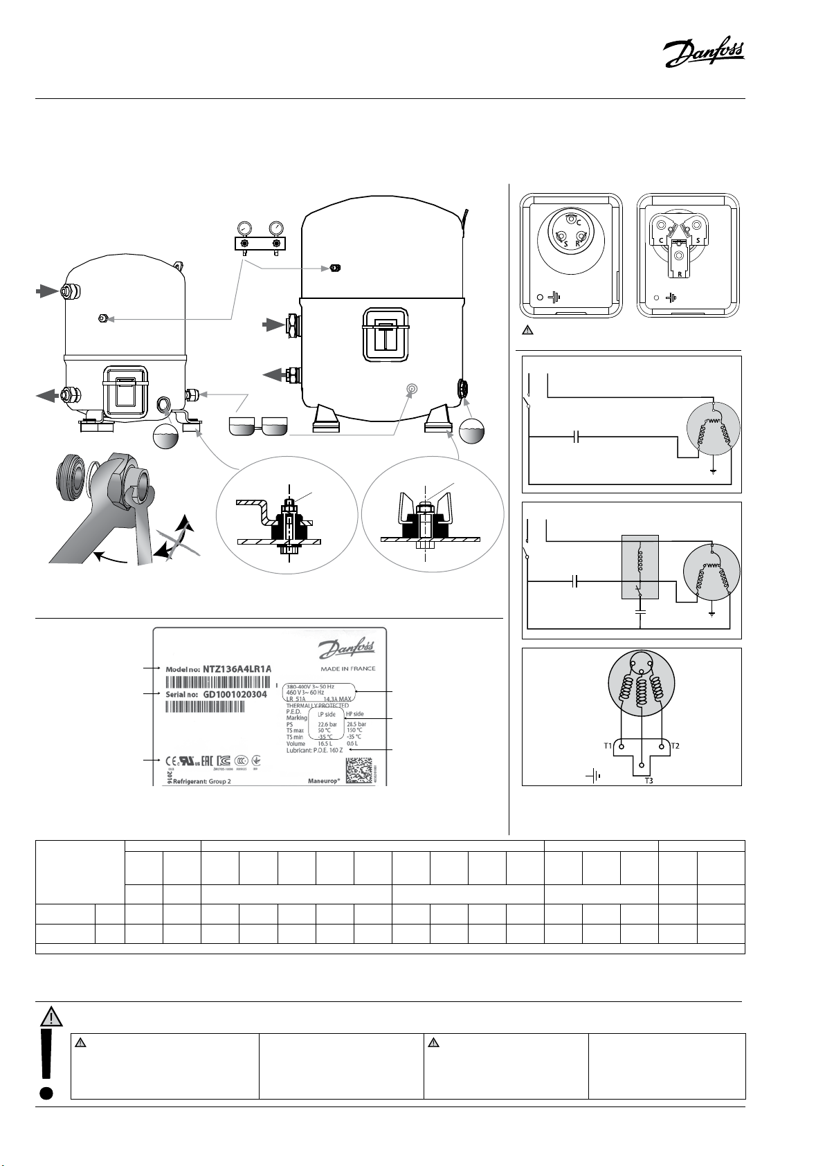
A: Model number D: Supply voltage, Starting current & Maximum current
B: Serial number E: Housing service pressure
C: Certication logo: Contact Danfoss F: Factory charged lubricant
MT MTZ VTZ NTZ
7.87 -
22.6
0.06 -
4.72
R404A /
R452A R448A R449A R513A R407C R134a
R507
13.2 -
12.5 -
27.3
0.84 -
6.69
11.7 -
26.0
0.6 -
6.08
27.7
1.04 -
7.2
Refrigerant
Oil
High side
pressure range
Low side
pressure range
R22 R417A* R407A** R407C R407F** R134a
160PZ-
160P
175PZ*
10.9 -
9.32 -
11.6 -
bar (g)
bar (g)
27.7
1.01 -
6.89
25.5
0.54 -
5.66
25.8
0.53 -
5.94
12.5 -
29.4
1.43 -
6.55
175PZ-160PZ 175PZ 160PZ 175PZ
12.1 -
24.0
0.99 -
6.25
Discharge temperature must be kept lower than 130°C
11.7 -
25.9
0.6 -
6.07
TH : Thermostat SR : Start Relay
SC : Start Capacitor RC : Run Capacitor
IOL : Motor Protector
8.37 -
23.36
0.21 -
5.12
* When MT compressors are used with R417A, the factory charged mineral oil 160P must be replaced by polyolester oil 160PZ-175PZ.
** R407A and R407F are not used for China Market.
Installation and servicing of the compressor by qualied personnel only. Follow these instructions and sound refrigeration engineering practice relating to
installatio n, commissioning, maintenance and service.
The compressor is delivered under
nitrogen gas pressure (between 0.3
and 0.7 bar) and hence cannot be
connected as is; refer to the «assembly»
section for further details.
Under all circumstances, the
EN378 (or other applicable local safety
regulation) requirements must be
fullled.
The compressor must only be used for its
designed purpose(s) and within its scope of
application (refer to «operating limits»).
Consult Application guidelines and datasheet available from cc.danfoss.com
2 | © Danfoss | DCS (CC) | 2018.03
R404A/
R452A
R507
7.8 -
7.87 -
9.89 -
29.4
1.43 -
6.55
20.2
0.64 -
3.88
27.7
1.04 -
6.06
12.5 -
24.2
0.18 -
2.99
The compressor must be handled
with caution in the vertical position
(maximum oset from the vertical :
15°)
8510196P04H - FRCC.PI.049.A4.02
R404A/
R507
175PZ-
160Z/MPZ
13.2 -
27.7
0.05 -
3.34
Page 3

Instructions
1 - Introduction
These instructions pertain to the Maneurop® MT,
MTZ,VTZ & NTZ compressors used for refrigeration systems. They provide necessary information regarding safety and proper usage of this
product.
2 – Handling and storage
• Handle the compressor with care. Use the
dedicated handles in the packaging. Use the
compressor lifting lug and use appropriate
and safe lifting equipment.
• Store and transport the compressor in an
upright position.
• Store the compressor between -35°C and
50°C.
• Don’t expose the compressor and the packaging to rain or corrosive atmosphere.
3 – Safety measures before assembly
Never use the compressor in a ammable at-
mosphere.
• The compressor ambient temperature may
not exceed 50°C during o-cycle.
• Mount the compressor on a horizontal at
surface with less than 3° slope.
• Verify that the power supply corresponds to
the compressor motor characteristics (see
nameplate).
• When installing MTZ,VTZ or NTZ, use equipment specically reserved for HFC refrigerants
which was never used for CFC refrigerants.
• Use clean and dehydrated refrigeration-grade
copper tubes and silver alloy brazing material.
• Use clean and dehydrated system components.
• The piping connected to the compressor must
be exible in 3 dimensions to dampen vibrations.
4 - Assembly
• Slowly release the nitrogen holding charge
through the schrader port.
• Remove the gaskets when brazing rotolock
connectors.
• Always use new gaskets for assembly.
• Connect the compressor to the system as
soon as possible to avoid oil contamination
from ambient moisture.
• Avoid material entering into the system while
cutting tubes. Never drill holes where burrs
cannot be removed.
• Braze with great care using state-of-the-ar t technique and vent piping with nitrogen gas ow.
• Connect the required safety and control devices. When the schrader port is used for this,
remove the internal valve.
5 – Leak detection
Never pressurize the circuit with oxygen or
dry air. This could cause re or explosion.
• Do not use dye for leak detection.
• Perform a leak detection test on the complete
system.
• The low side test pressure must not exceed 25
bar.
• When a leak is discovered, repair the leak and
repeat the leak detection.
6 – Vacuum dehydration
• Never use the compressor to evacuate the
system.
• Connect a vacuum pump to both the LP & HP
sides.
• Evacuate the system to a pressure of 500 µm
Hg (0.67 mbar) absolute.
• Do not use a megohmmeter nor apply power
to the compressor while it is under vacuum as
this may cause internal damage.
Danfoss can accept no responsibility for possible errors in catalogues, brochures and other printed material. Danfoss reserves the right to alter its products without notice. This
also applies to products already on order provided that such alterations can be made without subsequential changes being necessary in specications already agreed. All trademarks in this material are property of the respective companies. Danfoss and the Danfoss logotype are trademarks of Danfoss A/S. All rights reserved.
8510196P04H - FRCC.PI.049.A4.02
7 – Electrical connections
• Switch o and isolate the main power supply.
See overleaf for wiring details.
• The compressor is protected against excess
current and temperature by an internal overload protector. Follow local regulations regarding power line protection. The compressor
must be connected to earth.
• All electrical components must be selected as per
local standards and compressor requirements.
8 – Filling the system
• Keep the compressor switched o.
• Fill the refrigerant in liquid phase into the
condenser or liquid receiver. The charge must
be as close as possible to the nominal system
charge to avoid low pressure operation and
excessive superheat.
• Keep the refrigerant charge below 2.5 kg per
compressor cylinder if possible. Above this
limit; protect the compressor against liquid
ood-back with a pump-down cycle or suction line accumulator.
• Never leave the lling cylinder connected to
the circuit to avoid overlling.
9 – Verification before commissioning
Use safety devices such as safety pressure
switch and mechanical relief valve in compliance
with both generally and locally applicable regulations and safety standards. Ensure that they
are operational and properly set.
Check that the settings of high-pressure swit-
ches and relief valves don’t exceed the maximum
service pressure of any system component.
• A low-pressure switch is recommended to
avoid vacuum operation. Minimum setting
0.1 bar.
• Verify that all electrical connections are properly fastened and in compliance with local
regulations.
• When a crankcase heater is required, it must be
energized at least 12 hours before initial startup and start-up after prolonged shutdown.
10 – Start-up
• All service valves must be in the open position.
• Balance the HP/LP pressure.
• Energize the compressor. It must start
promptly. If it does not, switch it o
immediately. Possible single phase miswiring
can cause burn-out within seconds.
• If the compressor does not start, check wiring
conformity and voltage on terminals.
• If the internal overload protector trips out, it
must cool down to 60°C to reset. Depending
on ambient temperature, this may take up to
several hours.
11 – Check with running compressor
• Check current draw and voltage.
• Check suction superheat to reduce risk of
slugging.
• When a sight glass is provided observe the oil
level at start and during operation to conrm
that the oil level remains visible.
• Respect the operating limits as printed overleaf.
• Check all tubes for abnormal vibration. Movements in excess of 1.5 mm require corrective
measures such as tube brackets.
• When needed, additional refrigerant in the
liquid phase may be added in the low-pressure
side as far as possible from the compressor.
The compressor must be operating during
this process.
• Do not overcharge the system.
• Never release refrigerant to the atmosphere.
• Before leaving the installation site, carry out
a general installation inspection regarding
cleanliness, noise and leak detection.
• Record type and amount of refrigerant charge
as well as operating conditions as a reference
for future inspections.
12 - Maintenance
Internal pressure and surface temperature
are dangerous and may cause permanent injury.Maintenance operators and installers require
appropriate skills and tools. Tubing temperature
may exceed 100°C and can cause severe burns.
Ensure that periodic service inspections to
ensure system reliability and as required by local
regulations are performed.
To prevent system related compressor problems,
following periodic maintenance is recommended:
• Verify that safety devices are operational and
properly set.
• Ensure that the system is leak tight.
• Check the compressor current draw.
• Conrm that the system is operating in a way
consistent with previous maintenance records and ambient conditions.
• Check that all electrical connections are still
adequately fastened.
• Keep the compressor clean and verify the absence of rust and oxidation on the compressor shell, tubes and electrical connections.
13 - Warranty
Always transmit the model number and serial number with any claim led regarding this product.
The product warranty may be void in following
cases:
• Absence of nameplate.
• External modications; in particular, drilling,
welding, broken feet and shock marks.
• Compressor opened or returned unsealed.
• Rust, water or leak detection dye inside the
compressor.
• Use of a refrigerant or lubricant not approved
by Danfoss.
• Any deviation from recommended instructions pertaining to installation, application or
maintenance.
• Use in mobile applications.
• Use in explosive atmospheric environment.
• No model number or serial number transmitted with the warranty claim.
14 – Disposal
Danfoss recommends that compressors
and compressor oil should be recycled
by a suitable company.
© Danfoss | DCS (CC) | 2018.03 | 3
 Loading...