

Page 1
Pocket Guide
VLT® Soft Starter
– the single speed drive
Page 2

Page 3

Contents
Soft Starter Selection Guide
Warnings .................................................................................................................................... 5
Common Applications .......................................................................................................... 6
MCD Soft Starter Features and Specications ............................................................. 8
Current Ratings ........................................................................................................................11
Soft Starter Sizing ................................................................................................................. 13
FAQs
Adaptive Acceleration Control ......................................................................................... 14
AC53 Utilisation Codes ...................................................................................................... 15
Auto-Transformer Starters ............................................................................................... 16
Fault nding ............................................................................................................................. 16
Braking ....................................................................................................................................... 17
Bypass Contactor ................................................................................................................. 18
Cabling ..................................................................................................................................... 19
Extreme Conditions ............................................................................................................ 21
Flying Loads ........................................................................................................................... 22
Harmonics .............................................................................................................................. 22
IP Ratings ................................................................................................................................ 23
NEMA Ratings ........................................................................................................................ 24
Inside delta Connection .....................................................................................................25
Key Benets ........................................................................................................................... 26
Line Contac tor ...................................................................................................................... 27
Minimum Start Current ..................................................................................................... 28
Multiple Motors .................................................................................................................... 29
Power factor correction .................................................................................................... 30
Motor Thermal Capacity ................................................................................................... 30
Jog ............................................................................................................................................... 31
Reversing ................................................................................................................................ 31
Sealed Enclosures ................................................................................................................ 32
Primary Resistance Starters ............................................................................................. 32
Short Circuit Protection, Type 1 ...................................................................................... 33
Short Circuit Protection, Type 2 .......................................................................................34
Semiconductor Fuse Selection, Type 2 ........................................................................ 35
Slip-Ring Motors .................................................................................................................. 38
Soft Braking ........................................................................................................................... 39
Danfoss Drives · DKDD.PB.551.A1.02 | 3
Page 4

Star/Delta Starters ............................................................................................................... 40
Thermal Model Protection ............................................................................................... 42
Two Speed Motors .............................................................................................................. 43
Types of Soft Starter ........................................................................................................... 44
MCD Bus Options
MCD Bus Options – General Notes ................................................................................ 45
MCD 500 with MCD Remote Operator Option .......................................................... 46
MCD 500 Modbus Option ................................................................................................. 48
MCD 500 DeviceNet Option ............................................................................................. 49
MCD 500 PROFIBUS Option .............................................................................................. 50
MCD 500 USB Option ........................................................................................................... 51
MCD 200 with MCD Remote Operator Option .......................................................... 52
MCD 200 Modbus Option .................................................................................................. 53
MCD 200 DeviceNet Option .............................................................................................. 55
MCD 200 Probus Option .................................................................................................. 56
MCD 200 USB Option ........................................................................................................... 57
Glossary
Glossar y ....................................................................................................................................58
Abbreviations .........................................................................................................................63
4 | Danfoss Drives · DKDD.PB.551.A1.02
Page 5

Warnings
Soft starter selection requires information on the
intended application, the features required, and
the curre nt rating of the associated motor.
For applications with extreme or unusual conditions, consult the
relevant Design Guide and/or your supplier.
For example:
• High altitude installation (> 1000 m)
• High ambient temperatures (> 40˚ C)
• High and/or frequent operating overloads
• High start frequency
• Slip-ring motor operation
• Part speed operation
• Horizontal mounting of the starter
Danfoss Drives · DKDD.PB.551.A1.02 | 5
Page 6
Common Applications
This table lists common applications for soft starters, and their
nominal duty ratings.
Application Normal Heavy Severe
Agitator •
Auger •
Blower (axial fan) •
Bottle Washer •
Centrifuge •
Chipper •
Compressor, centrifugal (rotary) •
Compressor (reciprocating, unloaded) •
Compressor (screw, unloaded) •
Conveyor (loaded) •
Conveyor (unloaded) •
Crusher, cone •
Crusher, jaw •
Crusher, rotary (unloaded) •
Debarker •
Drilling machine •
Dust collector •
Edger •
Escalator •
Fan, centrifugal (damped) •
Fan, centrifugal (undamped) •
Grinder •
Hydraulic power pack •
Mill, ball •
Mill, hammer •
Mill, roller •
Milliscreen •
6 | Danfoss Drives · DKDD.PB.551.A1.02
Page 7

Application Normal Heavy Severe
Mixer (low viscosity) •
Mixer (high viscosity) •
Pelletiser •
Planer •
Press •
Pump, bore •
Pump, centrifugal •
Pump, positive displacement •
Pump, slurry •
Pump, submersible •
Pump, vacuum •
Re-pulper •
Rotary table •
Sander •
Saw, band •
Saw, circular •
Shredder •
Separator, liquids •
Separator, solids •
Slabber •
Slicer •
Travelato r •
Tumbler/Dryer •
Vibrating screen •
Winch •
Wire draw machine (hydraulic) •
Danfoss Drives · DKDD.PB.551.A1.02 | 7
Page 8
MCD Soft Starter Features and Specications
MCD 500
• Soft start: Current limit, Current
ramp, Kickstart, AAC Adaptive
Acceleration Control
• Soft stop: Timed voltage ramp,
AAC Adaptive Control, DC brake
• Motor protection: Motor connection, Power loss, Phase loss, Mains
frequency, Current imbalance,
Motor thermistor, Motor overload
• System protection:
Phase sequence, Excess start time,
Undercurrent, Instantaneous
overcurrent, Bypass relay overload,
Heatsink temperature
• Metering: Current, Motor
temperature, Motor kW, motor kVA,
Motor pf
• Control option: Local control
panel plus remote inputs/outputs.
Dedicated output for MCD LCP 501
• Network communication: options
for DeviceNet, Modbus, PROFIBUS
and USB
• Bypass:
7.5 ~ 500 kW internally bypassed;
630 ~ 800 kW dedicated terminals
for external bypass connection
MCD 500
• Current: 7.5 kW ~ 800 kW @400 V
• Mains voltage: 200 ~ 690 VAC
• Supply frequency: 50/60 Hz
• Enclosure: 7.5 ~ 55 kW IP 20,
60 ~ 800 kW IP 00
Control Panel VLT® LCP 501
• Same user interface as
VLT® Soft Starter MCD 500
• Plug & play with MCD 500
• Copy/ paste of parameters
• Multiple monitoring setup
• Door-mount kit – 3 m cable
• IP 65 (NEMA 12)
8 | Danfoss Drives · DKDD.PB.551.A1.02
Page 9
MCD 2 01
• Soft start/stop:
Timed voltage ramp
• Motor protection: not included
• System protection:
not included
• Metering: not included
• Start/stop control: via inputs or via
optional controller
• Network communication: optional
• Bypass: Internally bypassed
MCD 202
• Soft start: Current limit
• Soft stop: Timed voltage ramp
• Motor protection:
Thermistor, Motor overload,
Phase imbalance
• System protection: Phase rotation,
Excess start time, Bypass overload
& Instantaneous overload
• Metering: optional extra
• Start/stop control: via inputs or via
optional controller
• Network communication: optional
• Bypass: Internally bypassed
MCD 201 and MCD 202
• Current: 7.5 kW ~ 110 kW @400 V
• Mains voltage: 200 ~ 575 VAC
• Supply frequency: 45 ~ 66 Hz
• Enclosure: 7.5 ~ 55 kW IP 20,
75 ~ 110 kW IP00
Danfoss Drives · DKDD.PB.551.A1.02 | 9
Page 10
MCD 100
• Micro Soft Start Controller for
motors up to 11 kW
• Extremely robust SCR design with
heavy ratings as standard
• Unlimited number of starts per hour
• Contactor style design for easy
selection, installation and commissioning
MCD 100
• Current: 1.5 kW ~ 11 kW @400 V
• Mains voltage: 208 ~ 600 VAC
• Control voltage: 24 – 480 VAC/VDC
• Enclosure: 1.5 ~ 11 kW IP 20
10 | Danfoss Drives · DKDD.PB.551.A1.02
Page 11
Current Ratings
These duty ratings dene the load requirements , not
the starter capabilities. Starter capability is specied
separately in User Manua ls, Product Guides and
WinStar t. Use these charts to select a soft starter for a
particular application.
Normal Heavy Severe
MCD 5-0 021B 21 (32) 17 (26) 15 (22)
MCD5 -0037B 37 (56) 31 (47) 26 (39)
MCD5-0043B 43 (65) 37 (56) 30 (45)
MCD5-0053B 53 (80) 46 (69) 37 (55)
MCD5-0 068B 68 (102) 55 (83) 47 (7 1)
MCD5-0084B 8 4 (126 ) 69 (10 4) 58 (87)
MCD5-0 089B 89 (134) 74 (112 ) 61 (92)
MCD5-0105B 105 (15 8) 95 (143) 7 8 (117 )
MCD 5-0131B 131 (197) 106 (159) 9 0 (136)
MCD5 -0141B 141 ( 212) 121 (181) 97 (14 6)
MCD5-0195B 195 (293) 160 ( 241) 134 (201)
MC D5- 0215B 215 (323) 178 (268) 149 (22 3)
MCD5-0245C 255 (383) 201 (302) 176 (264)
MCD5-0245B 245 (368) 19 4 (2 91) 169 (2 54)
MCD 5-0331B 331 (497 ) 266 (400) 229 (343)
MCD5-0360C 360 (540) 310 (465) 263 (395)
MCD5-0380C 380 (570) 359 (539) 299 (449)
MCD5- 0396B 396 (594) 318 (478) 27 3 (410)
MCD5-0428C 430 (645) 368 (552) 309 (4 63)
MCD5-0469B 469 (704) 383 (575) 326 (49 0)
MCD5-0525B 525 (787) 425 (637) 364 (546)
MCD5-0595C 620 (930) 540 ( 810) 434 (651)
MCD5 -0619 C 650 (975) 561 (8 42) 455 (683)
MCD5-0632B 632 (948) 512 (768) 438 (658)
MCD5-0790C 790 ( 1185 ) 714 (1072) 579 (869)
MCD5-0744B 744 (1116) 606 (910) 516 ( 774)
MCD5-0826B 826 (1239) 684 (1026) 571 (857)
MCD5-0927C 930 (1395) 829 (12 44) 6 61 (992 )
MCD5-09 61B 961 (14 41) 7 96 (119 4) 664 (997)
Danfoss Drives · DKDD.PB.551.A1.02 | 11
Page 12
Normal Heavy Severe
MC D5-12 00C 1200 (1800) 1200 (1800) 1071 (1607)
MCD5-1400C 1410 (2115) 1319 (197 9) 111 4 (16 71)
MCD5 -1600 C 1600 (2400) 1600 (2400) 13 53 (203 0)
All ratings are for bypassed operation.
Brackets denote ratings for inside delta connection.
Normal Heavy Severe
MCD 201-007 18 17
MCD 201-015 34 30
MCD 201-018 42 36
MCD 201-022 48 40
MCD 201-030 60 49
MCD 201-037 74 65
MCD 201-045 85 73
MCD 201-055 10 0 96
MCD 201-075 140 12 0
MCD 201-090 170 142
MCD 201-110 200 165
MCD 202- 007 18 17
MC D 202- 015 34 30
MCD 202-018 42 36
MCD 202- 022 48 40
MCD 202- 030 60 49
MCD 202-037 74 65
MCD 202- 045 85 73
MCD 202-055 10 0 96
MCD 202-075 140 12 0
MCD 202- 090 170 142
MCD 202- 110 200 165
Consult Danfoss
for suitability
Consult Danfoss
for suitability
12 | Danfoss Drives · DKDD.PB.551.A1.02
Page 13

Soft Starter Sizing
• Th e soft start er’s current ratin g at the required st art duty must b e at least equal to th e
motor’s nameplate rating. If the motor’s nameplate rating is not available, approximate
information is available from the following table.
Motor Power Current rating at dierent voltages
kW HP 220-230 V 380- 400 V 4 40 V 500 V 660-690 V
7.5 10 27 15 .5 13.7 12 8.9
11 15 39 22 20.1 18.4 14
15 20 52 30 26.5 23 17. 3
18.5 25 64 37 32.8 28.5 21. 3
22 30 75 44 39 33 25.4
25 35 85 52 45.3 39.4 30.3
30 40 103 60 51.5 45 34.6
37 50 12 6 72 64 55 42
45 60 150 85 76 65 49
55 75 18 2 10 5 90 80 61
75 100 240 13 8 125 10 5 82
90 125 295 17 0 14 6 129 98
110 150 356 205 178 156 11 8
132 18 0 425 245 215 187 14 0
140 19 0 450 260 227 200 145
147 200 472 273 236 2 07 15 2
150 205 483 28 0 246 210 15 9
160 220 520 300 256 220 170
185 250 595 342 295 263 20 0
200 270 626 370 321 281 215
220 300 700 408 353 310 235
250 340 800 460 4 01 360 274
257 350 826 475 412 365 280
280 380 900 510 450 400 305
295 400 948 546 473 416 320
300 410 980 565 4 81 420 325
315 430 990 584 505 4 45 337
335 450 110 0 620 518 472 355
355 480 115 0 636 549 50 0 370
375 500 118 0 670 5 75 527 395
400 545 12 50 710 611 540 410
425 580 133 0 760 650 574 4 45
445 60 0 140 0 790 680 595 455
450 610 1410 800 690 608 460
475 645 149 0 850 730 645 485
500 680 15 70 900 780 680 515
560 76 0 1750 1000 860 760 570
600 800 1875 10 85 937 825 625
650 870 2031 1176 1015 894 67 7
700 940 2187 126 6 1093 962 729
750 1000 2343 1357 1172 1031 781
800 1070 2499 1447 12 50 110 0 833
850 114 0 2656 1537 1328 11 68 885
900 1250 2812 162 8 140 6 12 37 937
950 127 5 2968 1718 1484 13 06 989
1000 1340 3124 180 9 156 2 13 75 10 41
Note: Inform ation is based on a 4- pole motor
Danfoss Drives · DKDD.PB.551.A1.02 | 13
Page 14
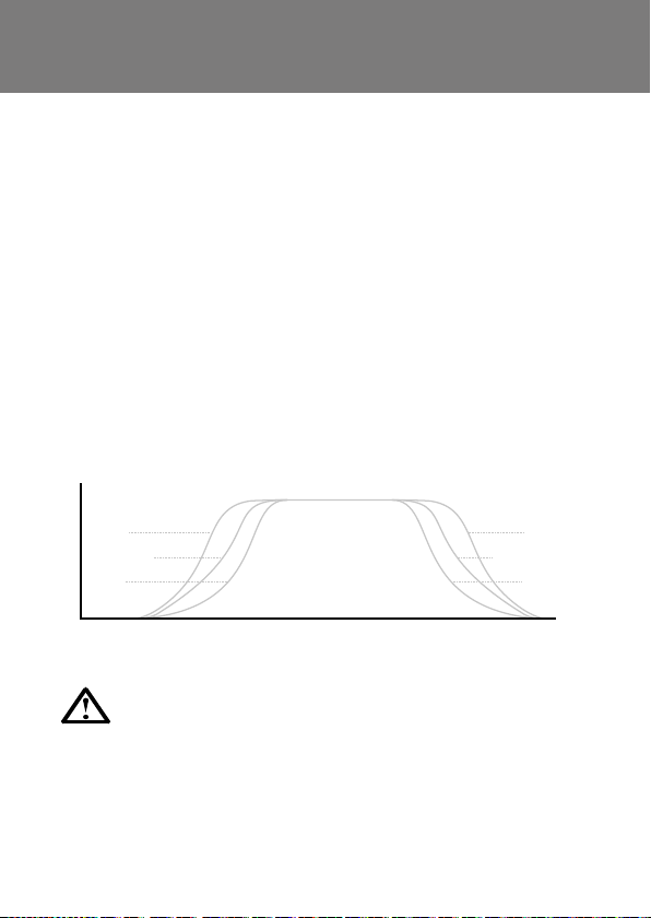
AAC: What is Adaptive Acceleration Control?
TIME
AAC is the next evolution in soft starter technology.
Using AAC, the soft starter learns your motor’s performance during
start and stop, then adjusts control to optimize performance.
The soft starter estimates the motor’s speed throughout each
AAC start and stop, and adjusts power to the motor to provide the
selected acceleration or deceleration profile.
AAC is largely unaffected by changes in load, and is particularly
suitable for pumping situations.
AAC offers three starting and stopping profiles: early, constant and
late acceleration/deceleration.
EARLY
CONSTANT
SPEED
LATE
AAC is only available on MCD 500 soft starters.
14 | Danfoss Drives · DKDD.PB.551.A1.02
LATE
CONSTANT
EARLY
Page 15
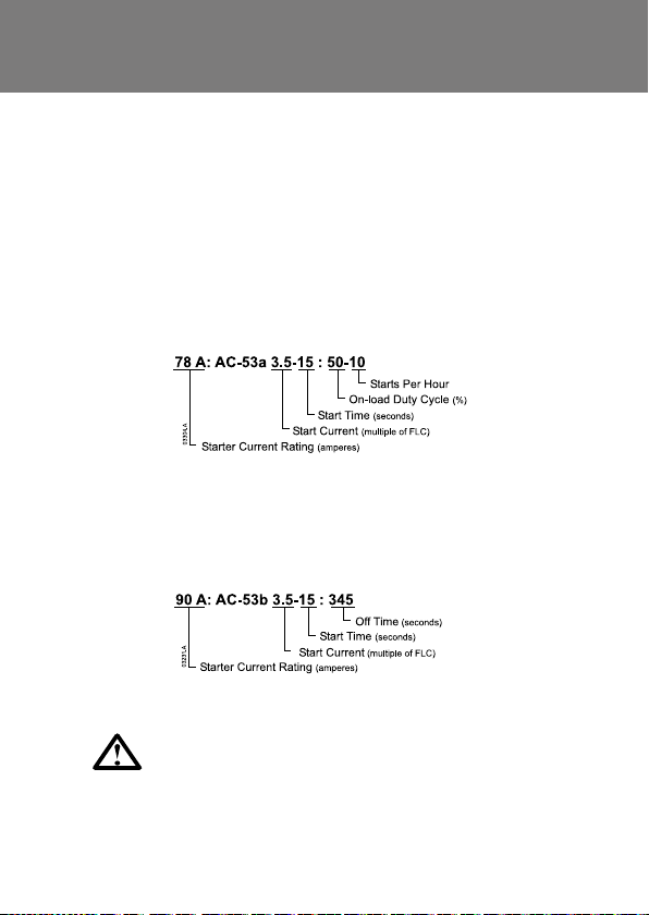
AC53 Utilisation Codes: What are AC53 Utilisation Codes?
AC53 utilisation codes describe the current rating for soft starters
under specied operating conditions.
The utilisation code determines the maximum motor size the
soft starter can be used with, under the specied conditions. The
current rating may change under dierent operating conditions.
AC53a: Non-bypassed soft starters
The rating depends on the number of starts per hour, the length
and current level of the start, and the percentage of the operating
cycle that the soft starter will be running (passing current).
AC53b: Bypassed soft starters
The rating depends on the number of starts per hour, the length
and current level of the start, and the amount of time the soft
starter will be o (not passing current) between starts.
Danfoss soft starters provide a relay output, which can
be used to control the main contactor. Ensure that the
inrush VA rating of the contactor coil does not exceed
the rating of the sof t starter’s relay input.
Danfoss Drives · DKDD.PB.551.A1.02 | 15
Page 16

Auto-Transformer Starters: How does soft start
compare to auto-transformer starting?
Soft starters are much more exible than auto-transformer starters
and provide a much smoother start, generally at a lower cost.
Auto-transformer starters cannot accommodate varying load
conditions (e.g. loaded or unloaded starts) and the start torque
cannot be freely adjusted to match motor and load characteristics.
Damaging torque and current transients still occur at the steps
between voltages, and auto-transformer starters are not capable
of providing soft stop. Auto-transformer starters are large and
expensive, especially if high start frequency is required.
Fault nding: What are the key questions?
To assist your service engineer, they require the following
information:
• Model and serial number of the soft starter
• Motor kW and FLC
• Main supply voltage and frequency
• Control voltage
• Application (e.g. pump, compressor)
• Time installed before failure
• Details of other soft starters on the supply bus. Are these failing?
• If the soft starter trips, details of the code and mode of operation
• The installation’s power and control schematic diagram
16 | Danfoss Drives · DKDD.PB.551.A1.02
Page 17
Braking:
What are DC braking and soft braking?
DC braking and soft braking both reduce motor stopping time,
unlike soft stopping which increases the stop time on frictional
loads.
DC braking uses DC injection to reduce the motor’s stopping time.
The soft starter slows the motor to approximately 70% of its full
running speed, then applies brake torque to stop the motor in the
selected braking time.
DC braking support is built into MCD 500 soft starters, and no
additional equipment is required. MCD 500 DC braking controls all
three phases, which reduces stress on the motor compared with
two phase braking solutions.
Soft braking uses reversing contactors on the input side of the
starter to start the motor in the reverse direction, which applies
braking torque to the load.
Soft braking causes less motor heating and provides more
braking torque for a given current than DC braking, and is better
for extremely high inertia loads (e.g. band saw and circular saw
applications).
Danfoss Drives · DKDD.PB.551.A1.02 | 17
Page 18
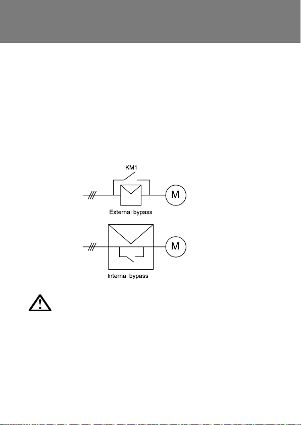
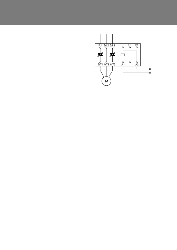
Bypass Contactors:
When should a bypass contactor be used?
Bypass contactors bridge out the SCRs when the motor is running
at full speed, eliminating heat dissipation during run. This allows
the soft starter to be installed in enclosures without the need for
forced-air cabinet ventilation.
If a soft starter is installed in a totally sealed enclosure (>IP 54) it
must be bypassed.
Bypass contactors should be AC1 rated for the motor FLC (the
bypass contactor does not carry start current).
Soft starters may be internally or externally bypassed:
MCD 200 sof t starters are i nternally bypas sed,
with built-in bypass relays.
MCD 500 sof t starters are i nternally bypas sed up to 500 kW.
Non-bypassed models include relay outputs to control an
external bypass contactor. Dedicated bypass terminals
mean moto r protection sti ll operates even when the sta rter
is bypassed.
18 | Danfoss Drives · DKDD.PB.551.A1.02
Page 19
Cabling: How is cable selected for
a soft starter installation?
Cable selection criteria depends on the circuit and the location of
the soft starter within the circuit.
1. Supply cable rating > nominal fuse/MCCB rating > motor FLC x 1.2
2. Inside delta motor circuit cable rating > motor FLC x 0.7
Installation factors (including grouping, ambient
temperature, method of installation and single or
parallel cabling) may aect the cable’s current rating.
Always follow the manufacturer’s guidelines and derate
appropriately.
Danfoss Drives · DKDD.PB.551.A1.02 | 19
Page 20

Cabling: What is the maximum allowable cable,
distance between a soft starter and the motor?
The maximum distance between the soft starter and motor
depends on the voltage drop and the cable capacitance.
Cable must be selected so that when the motor is running fully
loaded, the voltage drop at the motor terminals does not exceed
the limit specied in local electrical regulations.
For distances greater than 500 metres or when using parallel
cabling, cable capacitance may be a factor. If in doubt, please
contact Danfoss with details of the soft starter model, mains
voltage and frequency. If you want to use standard products, we
recommend using Line Reactors.
Calculation
The main point is to limit the di/dt so the SCR’s are not damage
with the inrush currents due to increase cable capacitance. The
output inductors must be installed as close to the soft starter as
possible.
The output inductors must be smaller than the inductance of the
motor.
Minimum rated current of coil, is stated from start current.
(Soft starter selection and application, normally 3 – 4,5 x FLC)
V
p
< L
di
(
dt
)
Vp Vp = V
di
dt
V Motor supply voltage
Ilr Locked rotor current
ω 2 × π × frequency
L
Coil Inductance
coil
20 | Danfoss Drives · DKDD.PB.551.A1.02
V
coil
(√3 I
) ω
LR
× √2
rms
100 A
.
1 μS
Page 21

Example:
Compressor (Reciprocating, start unloaded), start current limited to
3,5 x FLC, motor: 132 kW, 400 V, In: 226 A, Ilr: 7,5 x In.
Mains Supply: 400 V, 50 Hz-
L
= Motor Inductance =
max
400 V × √2
L
=
min
10 0 A
(
1 μS
)
= 5,66 μH
(√3 x I
V
) ω
LR
400
(√3 x 1695) × (2 × π × 50)
= 0,434 mH=
Minimum rated current = 226 x 3,5 = 791 A
Extreme Conditions: How can soft starters be selected
for extreme conditions?
Soft starter ratings are based on specic operating conditions.
These generally specify start time, start current, starts per
hour, duty cycle and environmental factors such as ambient
temperature and altitude. If the soft starter will be used outside
these conditions, the rating must be revised according to the
manufacturer’s instructions.
Ratings for Danfoss soft starters are published in the
soft starter’s Operating Instructions. Alternatively,
WinStar t can be used to model requirements outside the
published ratings.
Danfoss Drives · DKDD.PB.551.A1.02 | 21
Page 22

Flying Loads: Are soft starters suitable for use
with a ying load?
Soft starters can be used with ying loads (motors that are already
rotating), without any special wiring or conguration.
As a general rule, the faster the motor is rotating in the forward
direction, the shorter the start time will be.
If the motor is rotating in the reverse direction, it will be slowed to
a standstill before accelerating in the forward direction. In this case
allow for the extended start time when rating the soft starter.
Harmonics: Are harmonics an issue for
soft starter applications?
Harmonics are voltages and currents that create unwanted heating
in motors, cables and other equipment. Harmonics may also
disrupt operation of other electrical and electronic equipment.
Soft starters generate very low levels of harmonics, only during
starting or soft stopping. According to IEC 60947-4-2 (8.3.2.1.1),
“harmonic emissions are of short duration during starting, and
there are no signicant emissions in the FULL-ON state”. No special
considerations or ltering are required for soft start applications.
All MCD soft star ters comply with the EMC directive on
radiofrequency emissions and immunity.
22 | Danfoss Drives · DKDD.PB.551.A1.02
Page 23

IP ratings
IEC 60529 species protection ratings for enclosures.
The rst number describes the protection against solid objects, the
second number describes the level of protection against entry of
liquids. Example IP 20 is highlighted below.
IP Solids
0 No protection No protection.
Protected agains t solid objects
1
greater tha n 50 mm (e.g.
accidental touching by hand).
Protected agains t solid objects
2
greater tha n 12 mm (e.g. ngers).
Protected agains t solid objects
3
greater tha n 2.5 mm
(e.g. tools or w ires)
Protected agains t solid objects
4
greater tha n 1 mm
(e.g. tools an d small wires).
Limited protection against dust
5
(some ingress but no har mful
deposit).
6 Complete protection against dust.
7
8
Examples
• MCD200- 007 ~ MCD200-055 is IP 20
• MCD200- 075 ~ MCD200-110 is IP 00
IP 20 with optional finger guard kit,
Order code 175G9007
• MCD5-0 021 ~ MCD5-0105 is IP 20
• MCD5-0131 ~ MCD5-1600 is IP 00
Liquids
Protected agains t vertically falling
drops of water (e.g. condensation).
Protected agains t direct sprays of
water up to 15° from vertical .
Protected agains t sprays of water
up to 60° from vertical.
Limited pr otection agains t water
sprayed fr om all directions (limited
ingress permitted).
Limited pr otection agains t low
pressure jets of water from all directions (limited ingress permitted).
Protected agains t strong jets of
water (limited ingress permitted).
Protected agains t the eects of
immersi on in water between 15 cm
and 100 cm.
Protected agains t extended
immersion in water under pressure.
Order codes for finger guard kits are:
MCD5-0131~0215: 175G5662
MCD5-0245: 175G5663
MCD5-0360~0927: 175G5664
MCD5-1200~1600: 175G5665
MCD5-0245~0396B: 175G5730
MCD5-0469~0961B: 175G5731
Danfoss Drives · DKDD.PB.551.A1.02 | 23
Page 24

NEMA ratings
NEMA 250 is a product standard for enclosure design and
performance.
NEMA Protection against solid objects Approx. IP equivalent
1 Indoor, protection from contact. IP 23
Indoor, limited protection from
2
dirt and water.
Outdoor, some protection from rain,
3
sleet, windblow n dust and ice.
Outdoor, some protection from rain,
3R
sleet and i ce.
Indoor or outdoor, some protection from
4
windblown dust, rain, splashing water,
hose-directed water and ice.
Indoor or outdoor, some protection
from corrosion, windblown dust, rain,
4X
splashing water, hose-directed water
and ice.
Indoor or outdoor, some protection from
6
ice, hose -directed water, entry of wa ter
when submerged at limited depth.
Indoor, protection from dust, falling dirt
12
and dripping non-corrosive liquids.
Indoor, protection from dust, spraying
13
water, oil and non-corrosive liquids.
Warning:
Conversion from NEMA to IEC (IP) degrees of enclosure not to be
used for converting from IEC to NEMA.
Please refer to NEMA publication 250, 2003.
IP 30
IP 64
IP 32
IP 66
IP 66
IP 67
IP 55
IP 65
24 | Danfoss Drives · DKDD.PB.551.A1.02
Page 25

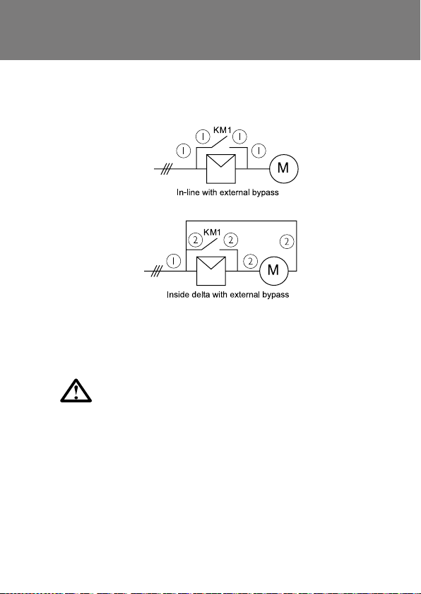
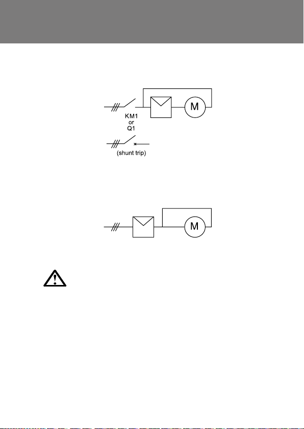
Inside delta Connection:
What is “inside delta” connection?
With inside delta (six wire connection), the soft starter SCRs are in
series with each motor winding so that the soft starter carries only
phase current, not line current. The soft starter can thus control a
motor with greater full load current than normal.
Inside delta connection is only possible with motors that allow
each end of all three motor windings to be connected separately,
and not all soft starters can be connected using inside delta. A line
contactor or shunt trip MCCB must always be used to disconnect
the motor and soft starter from the supply in the event of a trip.
Inside delta connection simplies replacement of star/delta starters
because the existing wiring can be used. In new installations,
inside delta connection may reduce the size and cost of the soft
starter, but there are additional costs for the line contactor/shunt
trip MCCB and extra cabling.
MCD 200 sof t starters cannot be installed using
inside delta connection.
MCD 500 sof t starters have built-in support for
inside delta connection.
Danfoss Drives · DKDD.PB.551.A1.02 | 25
Page 26

Key Benets: What are the key benets of soft start?
Soft start enhances motor start performance in many ways.
• The gradual application of voltage or current avoids the voltage
and current transients associated with electro-mechanical
reduced voltage starters.
• Acceleration is also smoother, as soft start avoids the torque
transients associated with electro-mechanical reduced voltage
starters.
• Constant current control gives higher torque as motor speed
increases, resulting in lower start currents and/or shorter start
times
• Start performance can be adjusted to suit the motor and load,
including exact control over the current limit.
• Soft starting provides reliable performance even with frequent
starts, or if load characteristics vary between starts (e.g. loaded
or unloaded).
Soft starters also provide a range of features not available from
other reduced voltage starters. This includes soft stop, which helps
eliminate water hammer and DC braking.
Other features such as built-in protection for the motor
and system, and metering and monitoring options, ca n
reduce the overall installed cost of the equipment and
reduce the long-term maintenance requirement.
26 | Danfoss Drives · DKDD.PB.551.A1.02
Page 27

Line Contactors: When should a line contactor be used?
Soft starters can be installed with or without a line contactor.
A line contactor disconnects the SCRs from the supply when the
motor is not in use. This isolates the soft starter, and protects the
SCRs from damage due to severe overvoltage (e.g. lightning strikes)
– SCRs are most susceptible to overvoltage damage when in the o
state. The soft starter is also isolated from the supply in the event
of a trip.
A line contactor may be required by local electrical regulations and
should be AC3 rated for the motor FLC.
The line contactor can be controlled via the soft star ter’s
relay output. The inrush VA rating of the contactor coil
must not exceed the rating of the soft starter’s relay
output.
Danfoss Drives · DKDD.PB.551.A1.02 | 27
Page 28

Minimum Start Current: What is the minimum start
current required by a soft starter?
Soft starters can limit start current to any specied level, but the
practical minimum depends on the motor and load. Reducing
the start current reduces the torque produced by the motor, so
the load will stall if the start current is too low. In order to start
successfully, the motor must produce more acceleration torque
than the load requires throughout the start.
Successful start:
Unsuccessful start:
Start current can be estimated based on previous experience, or
the motor and load speed/torque curves can be analysed for a
precise calculation.
28 | Danfoss Drives · DKDD.PB.551.A1.02
Page 29

Multiple motors: Can one soft starter be used
to control multiple motors?
A single soft starter can be used to control multiple motors, either
in sequence or in parallel, provided the soft starter is correctly
selected for the application.
Motors in sequence
For two or more motors in sequence, the soft starter must be
capable of bearing the total start duty.
Installation requires additional wiring, plus separate overload
protection and line and bypass contactors for each motor. The additional installation costs may be greater than the cost of individual
soft starters.
* This control method is complex and would require the use
of a PLC or smart relay.
Danfoss Drives · DKDD.PB.551.A1.02 | 29
Page 30

Power factor correction: Can power factor correction
be used with soft starters?
Power factor correction (PFC) capacitors can be used with soft
starters, provided they are switched in using a dedicated contactor
when the motor is running at full speed. PFC must always be
installed on the input side of the soft starter; connecting PFC
capacitors to the output of a soft starter causes resonance between
the inductance of the motor and the power factor capacitance,
resulting in severe overvoltage and equipment failure.
The contactor should be AC6 rated for the motor full load current.
PFC capacitors can be sized using the following formula:
kVA (Cap) = √_3 x V
x 0.8 x motor no load current
line
1000
Motor thermal capacity: What is it?
Thermal capacity, also called “maximum locked rotor time” or
“maximum DOL start time”, describes the maximum time a motor
can run at locked rotor current from cold. This information is
usually available from the motor datasheet.
The MCD 202 overload protection can be set to match the motors
thermal capability using the motors locked rotor time (cold).
30 | Danfoss Drives · DKDD.PB.551.A1.02
Page 31

Jog: What is the jog function?
Jog runs the motor at reduced speed, to allow alignment of the
load or to assist servicing. The motor can be jogged in either
forward or reverse direction. The maximum available torque
for jog is approximately 50% - 75% of motor full load torque
(FLT) depending on the motor. Available jog torque in reverse is
approximately 50% - 75% of the jog torque in forward direction.
This is ideal for positioning of loads such as mixers or hopper bins
ready for unloading.
Reversing: Can soft starters be used
to reverse motor direction?
On their own, soft starters cannot run motors in reverse direction
at full speed. However, an arrangement of forward and reverse
contactors can be used to provide the same effect.
MCD 500 soft starters offer a part speed function that runs the
motor at slow speed in either forward or reverse direction, without
a reversing contactor. Reverse operation is limited to short periods
at a fixed slow speed.
Danfoss Drives · DKDD.PB.551.A1.02 | 31
Page 32

Sealed enclosures: Can soft starters be installed
in sealed enclosures?
Soft starters can be installed in sealed enclosures, provided the
ambient temperature within the enclosure will not exceed the soft
starter’s rated temperature.
All heat generated within the enclosure must be dissipated, either by
ventilation or through the enclosure’s walls. This includes heat not
only from the soft starter but also from other components such as
fuses, cabling and switchgear. Heating from the soft starter can be
minimised by installing the starter in a bypassed conguration. To
minimise external heating, protect the enclosure from direct sunlight.
WinStart includes a function to help design enclosure ventilation.
Primary Resistance Starters: How does soft start
compare to primary resistance starting?
Soft starters are more exible and reliable than primary resistance
starters.
Primary resistance starters cannot accommodate varying load
conditions (e.g. loaded or unloaded starts) and the start torque cannot
be ne-tuned to match motor and load characteristics. Performance
may vary with multiple starts in close succession, because the start
prole changes as the resistance heats up. Damaging torque and
current transients still occur at the steps between voltages, and
primary resistance starters are not capable of providing sof t stop.
Primary resistance starters are large and expensive, and liquid
resistance starters require frequent maintenance.
32 | Danfoss Drives · DKDD.PB.551.A1.02
Page 33

Short Circuit Protection: What is required for Type 1 short
circuit protection of a soft starter?
Type 1 protection requires that in the event of a short circuit on the
output of a soft starter the fault must be cleared without risk of injury to
personnel. The soft starter may or may not be operational af ter the fault.
Type 1 protection is provided by HRC fuses or a MCCB within the motor
branch circuit, which must be able to bear the required motor start current.
Typical selection criteria are as follows:
Rating (% Motor FLC),
Start Current
Starter
type
MCD 200
MCD 500
* Consult the manufacturer’s specication.
Protection Type < 350% FLC
15 seconds
Fuse (non time delayed) 175 % 200%
Fuse (time delayed) 15 0% 175%
MCCB* 150 – 200%
Fuse (non time delayed) 150%
Fuse (time delayed) 12 5%
MCCB* 150 – 200%
> 350% FLC
15 seconds
Maximum fuse ratings for Type 1 motor protection are specied in
UL and IEC standards.
Fuse Rating (% Motor FLC)
Fuse (non-time delayed) 300%
Fuse (time delayed) 175%
Danfoss Drives · DKDD.PB.551.A1.02 | 33
Page 34

Short Circuit Protection: What is required for Type 2
short circuit protection of a soft starter?
Type 2 protection requires that in the event of a short circuit on
the output of a soft starter the fault must be cleared without risk of
injury to personnel or damage to the soft starter.
Type 2 protection is provided by semiconductor fuses, which must
be able to carry motor start current and have a total clearing I2t
less than the I2t of the soft starter SCRs.
Semiconductor fuses for Type 2 circuit protection are additional
to HRC fuses or MCCBs that form part of the motor branch circuit
protection.
Refer to the soft starter’s Design Guide for semiconductor fuse
recommendations.
34 | Danfoss Drives · DKDD.PB.551.A1.02
Page 35

Semiconductor Fuse Selection: Type 2
• Semiconductor fuses may be used with MCD soft starters. Use
of semiconductor fuses will provide Type 2 coordination and
reduce the potential of SCR damage due to transient overload
currents and short circuits. MCD soft starters have been tested
to achieve Type 2 coordination with semiconductor fuses. The
following table provides a list of suitable Bussman fuses. If
selecting alternate brands ensure the selected fuse has a lower
total clearing I2t rating than the SCR, and can carry start current
for the full start duration.
MCD 200
MCD200-007 17 0M-1 314 63 FE 1150
MCD 200 -015 170 M-1317 160 FE E 8000
MCD2 00- 018 17 0M-13 18 160 FEE 10500
MCD20 0-022 170M -1318 180 F M 15000
MCD20 0-030 170M -1319 180 F M 18000
MCD20 0-037 170M -1321 250 FM 512 00
MCD20 0-045 170M -1321 250 FM 80000
MCD20 0-055 170M -1321 250 FM 97000
MCD20 0-075 17 0M- 1322 500 FM M 168000
MCD20 0-090 17 0M- 302 2 500 FM M 245000
MC D20 0 -110 170M -3 022 500 FMM 320000
Bussmann Fuse
Square Body (170M)
200 ~575 V
Bussmann Fuse
Britis h Style (BS88)
Danfoss Drives · DKDD.PB.551.A1.02 | 35
SCR I
(A
2
t
2
s)
Page 36

• Semiconductor fuses listed below are manufactured by Bussman
and should be ordered directly from Bussman or their local
supplier. Instruction for selection for alternative semi-conductor
fuses is available from Danfoss.
1.1.1. Bussman Fuses – Square Body (170M)
MCD 500 SCR I2t (A2s)
MCD 5-0 021B 1150 170M13 14 17 0M1314 17 0M1314
MCD5 -0037B 8000 17 0M1316 17 0M1316 170M 1316
MCD5-0043B 105 00 170 M1318 170M1318 170M1318
MCD5-0053B 15000 170 M1318 170 M1318 170M1318
MCD5-00 68B 15000 170M1319 17 0M1319 170M1318
MCD5-00 84B 512000 170M 1321 170M1 321 170 M1319
MCD5-00 89B 80000 170 M1321 170 M1321 170 M1321
MCD5 -0105B 125000 170M13 21 17 0M1321 17 0M132 1
MCD 5-0131B 125000 170M1 321 17 0M132 1 17 0M1321
MCD 5-0 141B 320000 170M2621 170M2621 170M2621
MCD5-0195B 320000 170M2621 170M2621 170M2621
MCD 5- 0215B 320000 170M2621 170M2621 170M2621
MCD5- 0245B 320000 170M2621 170M2621 170M2621
MCD 5-03 31B 20200 0 17 0M 5011 170 M5 011 ––
MCD5- 0396B 320000 17 0M 6011 –– ––
MCD5-0469B 320000 170M6008* –– ––
MCD5- 0525B 781000 170 M6 013 170 M601 3 17 0M6 013
MCD5- 0632B 781000 170M 5015 17 0M5 015 ––
MCD 5- 0744B 1200000 17 0M5 017 170 M60 17 ––
MCD5-0 826B 2530000 170 M60 17 17 0M6 017 ––
MCD 5-0 961B 2530000 170M 6018 170 M6 013* ––
MCD5- 0245C 320000 170M2621 170M2621 170M2621
MCD5-036 0C 320000 17 0M6 010 170 M60 10 170 M601 0
MCD5-038 0C 320000 170M 60 11 17 0M6 011 ––
MCD5-0428C 320000 170 M6 011 17 0M 6011 ––
MCD5-0595C 1200000 170 M601 5 170 M6 015 170 M60 14
MCD 5-0 619C 1200000 170 M60 15 17 0M6 015 170 M60 14
MCD5- 0790C 2530000 17 0M6 017 170 M60 17 17 0M6 016
MCD5- 0927C 4500000 17 0M6 019 170 M60 19 17 0M6 019
MC D5-120 0C 4500000 17 0M6 021 –– ––
MCD 5-1410C 6480000 –– –– ––
MCD 5-160 0C 12500000 17 0M6 019* –– ––
Supply Voltage
≤ 440 VAC
Supply Voltage
≤ 575 VAC
Supply Voltage
≤ 690 VAC
* Two parallel connected fuses required per phase.
36 | Danfoss Drives · DKDD.PB.551.A1.02
Page 37

1.1.2. Bussman Fuses – British Style (BS88)
MCD 500 SCR I2t (A2s)
MCD 5-0 021B 1150 63FE 63FE 63FE
MCD5 -0037B 8000 120 FEE 120F EE 12 0FE E
MCD5-0043B 105 00 12 0FE E 120 FEE 120F EE
MCD5-0053B 15000 200 FEE 200 FEE 20 0FEE
MCD5-00 68B 15000 200 FEE 20 0FEE 2 00FEE
MCD5-00 84B 512000 2 00FEE 200FEE 200FEE
MCD5-00 89B 80000 280FM 280FM 28 0FM
MCD5 -0105B 125000 280FM 28 0FM 280FM
MCD 5-0131B 125000 280FM 2 80FM 280FM
MCD 5-0 141B 320000 450FM M 450FMM 450FM M
MCD5-0195B 320000 450FM M 450FMM 450FM M
MCD 5- 0215B 320000 450FMM 450 FMM 450FMM
MCD5- 0245B 320000 450FMM 45 0FMM 450FMM
MCD 5-03 31B 20200 0 315FM * –
MCD5- 0396B 320000 400FMM* –– ––
MCD5-0469B 320000 450FMM* –– ––
MCD5- 0525B 781000 500FMM* 500FMM * 5 00FMM*
MCD5- 0632B 781000 630FM M* –
MCD 5- 0744B 1200000 –– –– ––
MCD5-0 826B 2530000 –– –– ––
MCD 5-0 961B 2530000 –– –– ––
MCD5- 0245C 320000 450FMM 450 FMM 450FMM
MCD5-036 0C 320000 – –– ––
MCD5-038 0C 320000 400FM M* 400 FMM 400 FMM*
MCD5-0428C 320000 – –– ––
MCD5-0595C 1200000 6 30FMM* 630 FMM* ––
MCD 5-0 619C 1200000 630FMM* 630FMM* ––
MCD5- 0790C 2530000 –– –– ––
MCD5- 0927C 4500000 –– –– ––
MC D5-120 0C 4500000 –– –– ––
MCD 5-1410C 6480000 –– –– ––
MCD 5-160 0C 12500000 –– –– ––
Supply Voltage
≤ 440 VAC
Supply Voltage
≤ 575 VAC
– ––
– ––
Supply Voltage
≤ 690 VAC
* Two parallel connected fuses required per phase.
Danfoss Drives · DKDD.PB.551.A1.02 | 37
Page 38

Slip-Ring Motors: Are soft starters suitable for use
with slip-ring motors?
Soft starters are suitable for use with slip-ring motors provided that
the motor can still deliver the torque required to accelerate the
load. Soft starters are not suitable if the load requires extremely
high start torque, or if the slip-ring motor is intended to provide
speed control. When considering a soft starter for slip-ring
applications, a trial should be conducted to verify the performance.
To develop starting torque, some resistance must remain in the
rotor circuit during motor starting. This resistance must be bridged
out using a contactor (AC2 rated for rotor current) once the motor
is running close to full speed.
Rotor resistance (R) can be sized using the following formula:
Where VR = open circuit rotor voltage
IR = full load rotor current
38 | Danfoss Drives · DKDD.PB.551.A1.02
Page 39

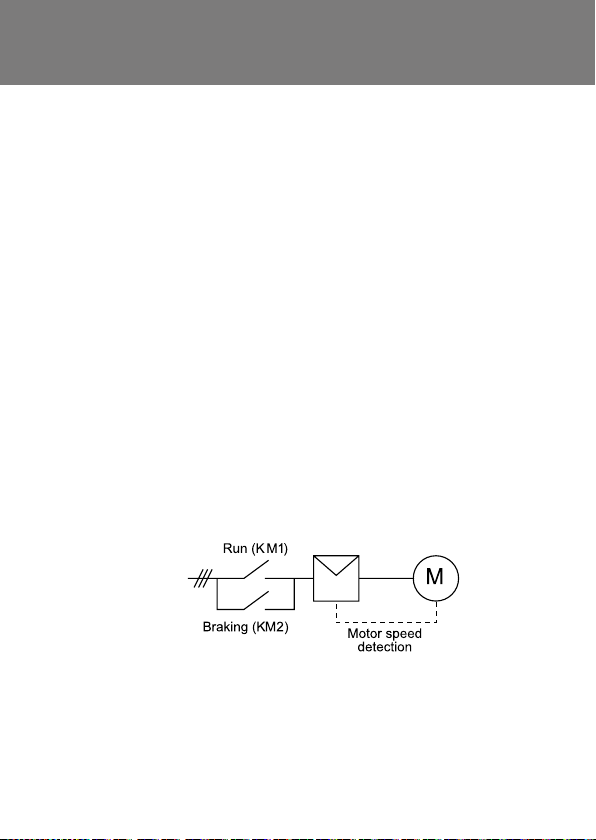
Soft Braking: What is soft braking?
Soft braking is a technique used by the soft starter to reduce
motor stopping time, unlike soft stopping which increases the stop
time on frictional loads. Soft braking requires the use of reversing
contactors.
When the soft starter receives a stop command, it operates the
reversing contactor connected on its input side to soft start the motor
in the reverse direction. This applies braking torque to the load.
Motor speed detection is required to shut down the braking at
motor standstill.
Soft starters can also use ‘DC braking’ to reduce the stopping time,
but soft braking causes less motor heating and provides more
braking torque for a given current, and is better for extremely high
inertia loads (e.g. band saw and circular saw applications).
Danfoss Drives · DKDD.PB.551.A1.02 | 39
Page 40

Star/Delta Starters: How does soft start compare
with star/delta starting?
Soft starters are much more flexible than star/delta starters and
provide a smooth start with no risk of transients.
Star/delta starters cannot accommodate varying load conditions
(e.g. loaded or unloaded starts) and the start torque cannot be
adjusted to match motor and load characteristics. In addition,
the open transition between star and delta connection causes
damaging torque and current transients. Star/delta starters are not
capable of providing soft stop.
However, star/delta starters may be cheaper than a soft starter and
they may limit the start current to a lower level than a soft starter
when used on an extremely light load. However, severe current
and torque transients may still occur.
40 | Danfoss Drives · DKDD.PB.551.A1.02
Page 41
Star/Delta Starters: Can soft starters be used
to replace star/delta starters?
If the soft starter supports inside delta connection, simply connect
it in place of the star/delta starter.
If the soft starter does not support inside delta connection,
connect the delta connection to the output side of the soft starter.
MCD 500 soft starters include built-in support
for inside delta connection.
Danfoss Drives · DKDD.PB.551.A1.02 | 41
Page 42

Thermal Model Protection: How is a motor thermal model
dierent from other forms of overload protection?
The motor thermal model used in MCD soft starters offers precise
motor protection normally only available from high-end motor
protection relays. The thermal model constantly models motor
temperature, based on information on the motor’s design
characteristics and actual operation. The thermal model accounts
for different heating and cooling rates when the motor is starting,
running or stopped. Accurate modelling allows the motor to be
used to its maximum potential without nuisance tripping.
The MCD 500 uses an advanced second order thermal
model, which models iron and copper losses separately.
This gives more prec ise modelling and provides greater
protection for the motor.
Compared with a motor thermal model, thermal overload relays
are less precise.
They do not account for iron loss or for different cooling rates at
different stages of motor operation, and cannot be adjusted to
match the characteristics of the individual motor because the mass
of the bimetal strips is fixed. The bimetal strips are also affected by
their own ambient temperature, which may be different from the
motor’s ambient temperature.
Thermal modelling is also superior to inverse time-current and
I2T electronic overloads, which do not account for iron loss or for
different cooling rates at different stages of motor operation. They
offer only limited adjustment and the trip curves do not closely
match motor heating. Inverse time-current protection also does
not allow for motor temperature before the overload.
42 | Danfoss Drives · DKDD.PB.551.A1.02
Page 43

Two-Speed Motors: Are soft starters suitable for use
with two-speed motors?
Soft starters are suitable for use with Dahlander and dual winding
motors, provided that separate motor protection is used for both
low and high speed operation.
Dual-winding motors have one shaft with two separate pole
congurations (e.g. 4 pole and 8 pole), providing two dierent
speeds. The speed is selected using external contactors (AC3
rated).
Dahlander motors are often used for two-speed compressor or
fan applications. The motor windings are externally congured
using contactors for high speed (dual star) and low speed (delta)
operation.
MCD 201 soft starters are designed for use with external
motor protection devices and are ideal for two-speed
motor applications. MCD 202 soft starters have motor
protection built in and are less suitable for two-speed
applications.
Danfoss Drives · DKDD.PB.551.A1.02 | 43
Page 44

Types of Soft Starter: What are the dierent types
of soft starters?
There are three dierent types of soft starter which oer dierent
features and control the motor in dierent ways.
1. Torque controllers control only one phase during start. This
reduces the torque shock at start but does not reduce start
current. Torque controllers must be used in conjunction with a
direct on-line starter.
2. Soft starters which control two phases can reduce start current
as well as eliminating torque transients, and are suitable for
normal and heavy duty loads, but not severe loads. The start
current on the uncontrolled phase is slightly higher than the two
controlled phases.
3. Soft starters which control all three phases provide the
maximum level of soft start control and are the only soft start
solution that is suitable for severe duty applications.
44 | Danfoss Drives · DKDD.PB.551.A1.02
Page 45

MCD Bus Options – General Notes
All bus options have the ability to:
• Control the soft starter
• Monitor the soft starter status
• Monitor the soft starter trip state
• Monitor the soft starter current (not available on MCD 201)
• Monitor the soft starter thermal model overload temperature
(not available on MCD 201)
Parameters can also be uploaded to or downloaded from MCD 500
soft starters on Modbus, DeviceNet or PROFIBUS networks.
In order for the MCD 500 to accept commands from the serial
network, the soft starter must be in Auto On mode and links must
be fitted to terminals 17 and 25 to 18. In Hand On mode, the starter
will not accept commands from the serial network but the starter’s
status can still be monitored.
The following information is a general guide to MCD 500 and MCD
200 bus options. Refer to the relevant installation instructions and
users manual for more detail.
Danfoss Drives · DKDD.PB.551.A1.02 | 45
Page 46

MCD 500 with Control Panel VLT® LCP 501
The VLT® LCP 501, Cat. No. 175G0096 ensures seamless plug and
play communication and control of VLT® Soft Starter MCD 500.
Full control and monitoring
The screen view set-up is selected from 7 standard views and one
user programmable.
Language selection:
English, Chinese, German, Spanish, Portuguese, French, Italian,
Russian.
The VLT® LCP 501 is connected to the MCD 500 by using a 3 m cable
using 9 pin (D-sub) plug and 3m cable provided with the IP 65
(NEMA 12) door-mount kit.
Control Panel VLT® LCP 501
• Same user interface as VLT® Soft Starter MCD 500
• Plug & play with MCD 500
• Copy/ paste of parameters
• Multiple monitoring setup
• Door-mount kit – 3 m cable
• IP 65 (NEMA 12)
The MCD LCP 501 (Cat. No: 175G0096) can be connected directly to
the dedicated output on MCD 500 (v10 and later). The LCP 501 can
be mounted up to 3 metres away from the starter, for control and
monitoring. The starter can be controlled and programmed from
either the remote LCP or the LCP on the starter. Both displays show
the same information.
46 | Danfoss Drives · DKDD.PB.551.A1.02
Page 47

MCD500
(Auto On mode)
Cat. No: 175G0096
Notes
• MCD LCP 501 includes one LCP and complete mounting kit (3
metre cable, gasket, screws).
• No set-up or configuration is required for the Control Panel VLT®
LCP 501. No external power is required.
• Control Panel VLT® LCP 501 can be used to transfer parameters
between multiple starters with the same software version.
• Control Panel VLT® LCP 501 is not compatible with MCD 200 soft
starters.
• Upgrade kit is available to enable use with MCD 500 v9 and
earlier.
Danfoss Drives · DKDD.PB.551.A1.02 | 47
Page 48

MCD 500 Modbus Option
This requires an MCD Modbus Module which clips onto the side of
the MCD 500 (Cat. No: 175G9000).
MCD
MCD500
(Auto On mode)
Notes:
• A single Modbus Module is required for each MCD 500.
• Modbus Module settings are provided using two 8-way DIP
switches on the module.
• Up to 31 Modbus Modules can be used as Modbus slave devices
on a single Modbus RTU network.
• The Modbus Module is powered by the MCD 500.
• For more information about operating the MCD Modbus Module,
refer to the Installation Instructions (MG.17.Fx.02), located at
www.danfoss.com/drives.
Modbus
Module
-
B6
GND
B7
+
B8
Cat. No: 175G9000
RS485
connection
onto a
Modbus
RTU
network
48 | Danfoss Drives · DKDD.PB.551.A1.02
Page 49

MCD 500 DeviceNet Option
This requires an MCD DeviceNet Module which clips onto the side
of the MCD 500 (Cat. No: 175G9002).
MCD
MCD500
(Auto On mode)
Notes
• A single DeviceNet Module is required for each MCD 500.
• DeviceNet node address (MAC ID) and data rate are selected
using three rotary switches on the DeviceNet Module.
• Up to 63 DeviceNet Modules can be used as DeviceNet slaves on
a single DeviceNet network.
• The DeviceNet Module is powered via the network cable.
• The MCD DeviceNet Module is ODVA tested and certified.
• For more information on the MCD DeviceNet Module, refer to the
Installation Instructions (MG.17.Hx.02), located at
www.danfoss.com/drives.
DeviceNet
Module
(V+)
RD
(CAN-H)
WH
(SHIELD)
(CAN-L)
BU
(V-)
BK
Cat. No: 175G9002
Standard 5-wire
connection onto a
DeviceNet network.
120 termination
resistors are required
at end of each end
of the network cable.
Danfoss Drives · DKDD.PB.551.A1.02 | 49
Page 50

MCD 500 Probus Option
This requires an MCD PROFIBUS Module which clips onto the side
of the MCD 500 (Cat. No: 175G9001).
MCD
MCD500
PROFIBUS
Module
Standard
DB9
connection
Cat. No: 175G9001
PROFIBUS DP
network cable
Notes:
• A single PROFIBUS Module is required for each MCD 500.
• The PROFIBUS node address is selected using two rotary
switches. Data rate is automatically detected.
• Up to 31 PROFIBUS Modules can be used as PROFIBUS slaves on a
single PROFIBUS DP network.
• The PROFIBUS Module requires an external 24 VDC auxiliary
supply.
• The MCD PROFIBUS Module is PROFIBUS tested and certified.
• For more information on the MCD PROFIBUS Module, refer to the
Installation Instructions (MG.17.Gx.02) at www.danfoss.com/
drives
50 | Danfoss Drives · DKDD.PB.551.A1.02
Page 51

MCD 500 USB Option
This is achieved using the MCD USB Module
(Cat. No: 175G9009).
MCD500
MCD
USB
Module
USB cable
Cat. No: 175G9009
Notes
• A single USB Module is required for each MCD 500
• The USB Module acts as a physical interface when using PC based
Master software such as WinMaster V4.x or MCT 10
• Driver software must be installed before the USB Module can be
used (supplied with the module on CD-ROM).
• For more information on the MCD USB Module, refer to the
Installation Instructions (MI.17.Cx.02) located at www.danfoss.
com/drives
PC
Danfoss Drives · DKDD.PB.551.A1.02 | 51
Page 52

MCD 200 with MCD Remote Operator Option
Cat. No: 175G9004
This requires an MCD Serial Interface Module which clips onto the
side of the MCD 200. It is supplied with the MCD Remote Operator
when ordering Cat. No: 175G9004.
MCD Remote Operator
RS485
Starter
-
GND GND
+
RS485
Network
B1
B2
B3
B6
B7
B8
-
+
MCD200
MCD
Serial
Interface
Module
69
GND
61
+
68
-
Notes
• A single MCD Remote Operator and MCD Serial interface Module
is required for each MCD 200.
• No set-up or conguration is required for operation.
• If two Remote Operators are required, the RS485 Network side
of the rst Remote Operator (terminals B6, B7, B8) must be connected to the RS485 Starter side of the second Remote Operator
(terminals B1, B2, B3). The rst Remote Operator is ordered using
Cat. No: 175G9004 and the second Remote Operator is ordered
using Cat. No: 175G3061.
• The Serial Interface Module is powered by the MCD 200. The
Remote Operator requires an external 18-30 VAC/DC auxiliary
supply.
• For more information on the MCD Remote Operator, refer to the
User Manual (MG.17.Ex.02)) located at www.danfoss.com/drives.
52 | Danfoss Drives · DKDD.PB.551.A1.02
Page 53

Cat. No: 175G9000
MCD 200 Modbus Option
There are two options to connect an MCD 200 to a Modbus network.
Option 1: Using an MCD Modbus Module (Cat. No: 175G9000)
MCD
MCD200
Notes
• A single Modbus Module is required for each MCD 200.
• Modbus Module settings are provided using two 8-way
DIP switches on the module.
• Up to 31 Modbus Modules can be used as Modbus slave devices
on a single Modbus RTU network.
• The Modbus Module is powered-up by the MCD 200.
• For more information about operating the MCD Modbus Module,
refer to the Installation Instructions (MG.17.Fx.02), located at
www.danfoss.com/drives.
Modbus
Module
-
B6
GND
B7
+
B8
RS485
connection
onto a
Modbus
RTU
network
Danfoss Drives · DKDD.PB.551.A1.02 | 53
Page 54

MCD 200 Modbus Option
Option 2: Using the MCD Remote Operator as a Modbus RTU
Gateway device (Cat. No: 175G9004)
MCD Remote Operator
RS485
Starter
B1
GND GND
B2
+
B3
Cat. No: 175G9004
RS485
Network
B6
B7
B8
-
+
RS485
connection
onto a
Modbus
RTU
network
MCD200
MCD
Serial
Interface
Module
69
GND
61
68
-
+
Notes:
• A single Remote operator and Serial Interface Module
is required for each MCD 200.
• Parameters 1 to 5 of the Remote Operator are used to set it up
as a Modbus slave device.
• Up to 31 Remote Operators can be used as Modbus slave devices
on a single Modbus network.
• The Serial Interface Module is powered via the MCD200. The
Remote Operator requires an external 18-30 VAC/DC auxiliary
supply.
• For more information about operating the MCD Remote Operator
as a Modbus RTU gateway, refer to the Installation Instructions
(MG.17.Fx.02), Appendix A, located at www.danfoss.com/drives.
54 | Danfoss Drives · DKDD.PB.551.A1.02
Page 55

MCD 200 DeviceNet Option
This requires an MCD DeviceNet Module which clips onto the side
of the MCD 200 (Cat. No: 175G9002).
MCD
MCD200
Notes
• A single DeviceNet Module is required for each MCD 200.
• DeviceNet node address (MAC ID) and data rate are selected
using three rotary switches on the DeviceNet Module.
• Up to 63 DeviceNet Modules can be used as DeviceNet slaves
on a single DeviceNet network.
• The DeviceNet Module is powered via the network cable.
• The MCD DeviceNet Module is ODVA tested and certied.
• For more information on the MCD DeviceNet Module, refer to the
Installation Instructions (MG.17.Hx.02), located at
www.danfoss.com/drives.
DeviceNet
Module
(V+)
RD
(CAN-H)
WH
(SHIELD)
(CAN-L)
BU
(V-)
BK
Cat. No: 175G9002
Standard 5-wire
connection onto a
DeviceNet network.
120 termination
resistors are required
at end of each end
of the network cable.
Danfoss Drives · DKDD.PB.551.A1.02 | 55
Page 56

MCD 200 Probus Option
This requires an MCD Probus Module which clips onto the side of
the MCD 200 (Cat. No: 175G9001).
MCD
MCD200
Profibus
Module
Standard
DB9
connection
Cat. No: 175G9001
Profibus DP
network cable
Notes:
• A single Probus Module is required for each MCD 200.
• Probus node address is selected using two rotary switches.
Data rate is automatically detected.
• Up to 31 Probus Modules can be used as Probus slaves
on a single Probus DP network.
• The Probus Module requires and external 24 VDC auxiliary supply.
• The MCD Probus Module is Probus tested and certied.
• For more information on the MCD Probus Module, refer to the
Installation Instructions (MG.17.Gx.02) at www.danfoss.com/drives.
56 | Danfoss Drives · DKDD.PB.551.A1.02
Page 57

MCD 200 USB Option
This is achieved using the MCD USB Module
(Cat. No: 175G9009).
MCD200
MCD
USB
Module
USB cable
Cat. No: 175G9009
Notes
• A single USB Module is required for each MCD 200
• The USB Module acts as a physical interface
when using PC based Master software such as
WinMaster V4.x or MCT10
• Driver software must be installed before the USB
Module can be used (supplied with the module
on CD-ROM).
• For more information on the MCD USB Module,
refer to the Installation Instructions (MI.17.Cx.02)
located at www.danfoss.com/drives
PC
Danfoss Drives · DKDD.PB.551.A1.02 | 57
Page 58

Glossary
AAC – Adaptive Acceleration Control. A new soft start control
technique that allows the soft starter to estimate the motor’s speed
and control it to match a selected acceleration or deceleration profile.
AC53 Utilisation Code – The specification of a soft starter’s
current rating and intended operating conditions.
Auger – a device which uses a screw-like mechanism to move
material or liquid, similar to the process that drives shavings up a
drill bit and out of a hole during drilling.
Blower – see Fan.
Bow thruster – a steering mechanism in large ships which uses
an impeller to force water through a tunnel in the bow below the
waterline, causing the ship to turn.
Centrifuge – a machine which separates materials of different
densities (e.g. solids from liquids or liquids from liquid mixtures).
Chipper – a machine which cuts large pieces of wood into chips.
Compressor, centrifugal – a machine which accelerates gas
through a housing then converts the velocity energy to pressure
energy. Normally used in heavy industrial applications.
Compressor, positive displacement – see Compressor, reciprocating.
Compressor, piston – see Compressor, reciprocating.
Compressor, reciprocating – a machine which compresses gas using
pistons driven by a crankshaf t. Small reciprocating compressors (up
to 30 HP) are suitable for intermittent use and are commonly found in
automotive applications. Larger units (up to 1000 HP) may be used for
large industrial applications.
Compressor, screw – a machine which forces gas into a smaller
space, using two meshed rotating positive-displacement screws.
Crusher – a machine which crushes material into smaller pieces.
Crusher, cone – a crusher consisting of two cones inside each other.
Material is fed into the top of the large, outer cone and is broken into
progressively smaller pieces by the rotation of the inverted inner cone.
58 | Danfoss Drives · DKDD.PB.551.A1.02
Page 59

Glossary
Crusher, jaw – a crusher with one fixed side and one moving “jaw”. The
crusher is wider at the top than the bottom, and material is fed in at the
top and moves down as it is broken into progressively smaller pieces.
Crusher, roller – a crusher with two horizontal rollers which rotate
in opposite directions, crushing the material into smaller pieces.
Current limit – (1) a method of soft starting a motor by limiting the
maximum amount of current the motor can draw during the start.
(2) The maximum amount of current the soft starter will allow a
motor to draw during a current limit start.
Current ramp – a method of soft starting a motor by gradually
increasing the amount of current from a specified point to the
current limit.
Debarker – a machine that strips bark from logs.
Decanter – a type of centrifuge.
Edger – a machine that cuts large pieces of timber into usable sizes.
Escalator – a type of conveyor which is used to move people up or
down, much like a moving staircase.
Fan, axial – a fan with blades that turn around a shaft, forcing air
along the shaft and across the axis of the fan.
Fan, centrifugal – a fan which pulls air in near the shaft and forces
it out through an opening in the outer edge of the fan casing. A
centrifugal fan produces more pressure for a given air volume than
an axial fan.
Fan, radial – see Fan, centrifugal.
Full load current – the amount of current a motor will draw when
operating fully loaded and at full speed.
Full load torque – the amount of torque a motor will produce
when operating fully loaded and at full speed.
Grinder – a machine which reduces the size of small particles
through compression and attrition. For machines operating on
larger items, see Crusher.
Danfoss Drives · DKDD.PB.551.A1.02 | 59
Page 60

Glossary
Gyratory crusher – see Crusher, cone.
Hydraulic power pack – A hydraulic pump which is used to supply
pressurised hydraulic fluid.
IP rating – a description of the soft starter’s level of physical
protection, according to IEC 60529.
Kickstart – a method of soft starting a motor which uses a high
level of current for a short period at the beginning of a current limit
or current ramp start.
Locked rotor current – the amount of current a motor will draw in
locked rotor situations, including full voltage starts. Locked rotor
current is described as a percentage of full load current.
Locked rotor time – the maximum amount of time a motor can
safely run at locked rotor current.
Locked rotor torque – the amount of torque a motor will produce
at locked rotor current (such as a full voltage start). Locked rotor
torque is described as a percentage of full load torque.
Mill, ball – a machine which grinds or mixes materials such as
ores, chemicals, ceramics and paints. The machine consists of a
horizontal cylinder which is rotated, causing the grinding medium,
commonly stainless steel balls, to repeatedly crush the material
inside into a powder.
Mill, hammer – a machine which crushes material into smaller
pieces. Hammers attached to rotating disks repeatedly strike the
material until it is small enough to fall through openings at the
bottom of the mill.
Mill, roller – a machine which crushes material into smaller pieces.
Material is passed between two horizontal rollers which rotate in
opposite directions, crushing the material into smaller pieces.
Milliscreen – a machine which separates solids from slurry, using
an inclined rotating drum with perforated sides.
Mixer – a machine which combines ingredients.
60 | Danfoss Drives · DKDD.PB.551.A1.02
Page 61

Glossary
Nameplate rating – See Full load current.
NEMA – a description of the soft starter’s physical format, accord-
ing to the National Electrical Manufacturers’ Association standard.
Pelletiser – a machine which turns powders into pellets.
Planer – a machine which draws boards over a cutting head to
reduce them to a specified thickness.
Press – a machine which changes the shape and internal structure
of metals (usually steel).
Pump – a machine which moves fluids.
Pump, bore – a submersible pump with a small diameter, suitable
for operation down bores.
Pump, centrifugal – a pump with an impeller which causes fluid
to rotate and move from the inlet to the outlet under its own
momentum. The fluid’s velocity increases as it progresses through
the impeller passage. Diffuser, ring or volute cavities reduce the
velocity of the fluid and convert the energy into pressure energy.
Pump, positive displacement – a pump which reduces the
volume of the pump chamber to cause the fluid to move. Positive
displacement pumps may be used for viscous fluids, and include
rotary (lobe, screw or gear pump) and reciprocating (piston or
diaphragm pump) types.
Pump, slurry – a centrifugal pump for pumping slurry.
Pump, submersible – a pump which is submerged in the fluid to
be pumped. The sealed motor is close-coupled to the pump body.
Pump, vacuum – a pump which removes gas from a sealed
chamber in order to create a partial vacuum. Multiple vacuum
pumps may be used together for a single application.
Re-pulper – a machine which re-pulps raw product for further
processing.
Rotary table – a large rotating table which is used to sort or move
material.
Danfoss Drives · DKDD.PB.551.A1.02 | 61
Page 62

Glossary
Sander – a machine which smooths raw material by abrading the
surface.
Saw – a machine which uses a serrated edge to cut materials.
Saw, band – a saw where the cutting edge is a long, thin strip of
metal with teeth on one side, commonly used for ripping lumber.
Saw, circular – a saw where the cutting edge is a large rotating
disk with teeth on the outer edge.
Screw feed – see Auger.
Separator – a type of centrifuge.
Shredder – a machine that tears objects such as paper, plastic or
wood into smaller pieces.
Slabber – a machine consisting of several saws, which cuts edged
logs into smaller pieces before further processing.
Slicer – a machine that slices materials, normally using more than
one blade.
Travelat or – a type of conveyor which is used to move people
along a flat or inclined surface.
Tumbler – a machine which rotates to turn material over during
drying or other processes.
Vibrating screen – a machine which separates particles of different sizes by vibrating horizontally. Smaller particles fall through
gaps in the plane.
Winch – a machine which winds ropes or cables.
Wire draw machine – a machine which draws metal wire through
progressively narrower dies to create finer wire.
62 | Danfoss Drives · DKDD.PB.551.A1.02
Page 63

Abbreviations
AC – Alternating Current
DC – Direct Current
DOL – Direct On Line
FLC – Full Load Current
FLT – Full Load Torque
HRC – High Rupturing Capacity
IP – Ingress Protection
kW – Kilowatt
LRC – Locked Rotor Current
MCCB – Moulded Case Circuit Breaker
PFC – Power Factor Correction
SCR – Silicon Controlled Rectier
TVR – Time Voltage Ramp
Danfoss Drives · DKDD.PB.551.A1.02 | 63
Page 64

 Loading...