

Page 1

MAKING MODERN LIVING POSSIBLE
Programming Guide
VLT® AutomationDrive
Page 2

Contents
Contents
VLT® AutomationDrive Programming Guide
1 Introduction
1.1.1 Approvals 3
1.1.2 Symbols 3
1.1.3 Definitions 3
1.1.4 Electrical Wiring - Control Cables 8
2 How to Programme
2.1 The Graphical and Numerical Local Control Panels
2.1.1 The LCD-Display 12
2.1.3 Display Mode 14
2.1.4 Display Mode - Selection of Read-Outs 14
2.1.5 Parameter Set-Up 15
2.1.6 Quick Menu Key Functions 15
2.1.8 Main Menu Mode 18
2.1.9 Parameter Selection 18
2.1.10 Changing Data 19
2.1.11 Changing a Text Value 19
2.1.12 Changing 19
3
11
11
2.1.13 Infinitely Variable Change of Numeric Data Value 19
2.1.14 Value, Step-by-Step 19
2.1.15 Read-out and Programming of Indexed Parameters 20
2.1.16 Local Control Keys 21
2.1.17 Initialisation to Default Settings 21
3 Parameter Descriptions
3.2 Parameters: 0-** Operation and Display
3.3 Parameters: 1-** Load and Motor
3.4 Parameters: 2-** Brakes
3.5 Parameters: 3-** Reference/Ramps
3.6 Parameters: 4-** Limits/Warnings
3.7 Parameters: 5-** Digital In/Out
3.8 Parameters: 6-** Analog In/Out
3.9 Parameters: 7-** Controllers
3.10 Parameters: 8-** Communications and Options
3.11 Parameters: 9-** Profibus
3.12 Parameters: 10-** DeviceNet CAN Fieldbus
23
24
34
52
57
67
72
91
100
106
112
112
3.13 Parameters: 12-** Ethernet
3.14 Parameters: 13-** Smart Logic Control
3.15 Parameters: 14-** Special Functions
3.16 Parameters: 15-** Drive Information
MG33MF02 - VLT® is a registered Danfoss trademark
112
112
125
133
1
Page 3

Contents
VLT® AutomationDrive Programming Guide
3.17 Parameters: 16-** Data Read-outs
3.18 Parameters: 17-** Motor Feedb. Option
3.19 Parameters: 18-** Data Readouts 2
3.20 Parameters: 30-** Special Features
3.21 Parameters: 35-** Sensor Input Option
4 Parameter Lists
4.1.1 Conversion 154
4.1.2 Active/Inactive Parameters in Different Drive Control Modes 154
5 Troubleshooting
5.1.1 Warnings/Alarm Messages 192
Index
138
145
147
148
151
153
192
204
2 MG33MF02 - VLT® is a registered Danfoss trademark
Page 4
Introduction
VLT® AutomationDrive Programming Guide
1 Introduction
Programming Guide
Software
This Programming Guide can be used for all FC 300 frequency
converters with software version 6.7x.
The software version number can be seen from 15-43 Software
Version.
Table 1.1
version: 6.7x
1.1.1 Approvals
Table 1.2
1.1.2 Symbols
The following symbols are used in this manual.
WARNING
Indicates a potentially hazardous situation which, if not
avoided,
could result in death or serious injury.
CAUTION
Indicates a potentially hazardous situation which, if not
avoided,
may result in minor or moderate injury. It may
also be used to alert against unsafe practices.
CAUTION
Indicates
property-damage-only accidents.
NOTE
Indicates
with attention to avoid mistakes or operate equipment at
less than optimal performance.
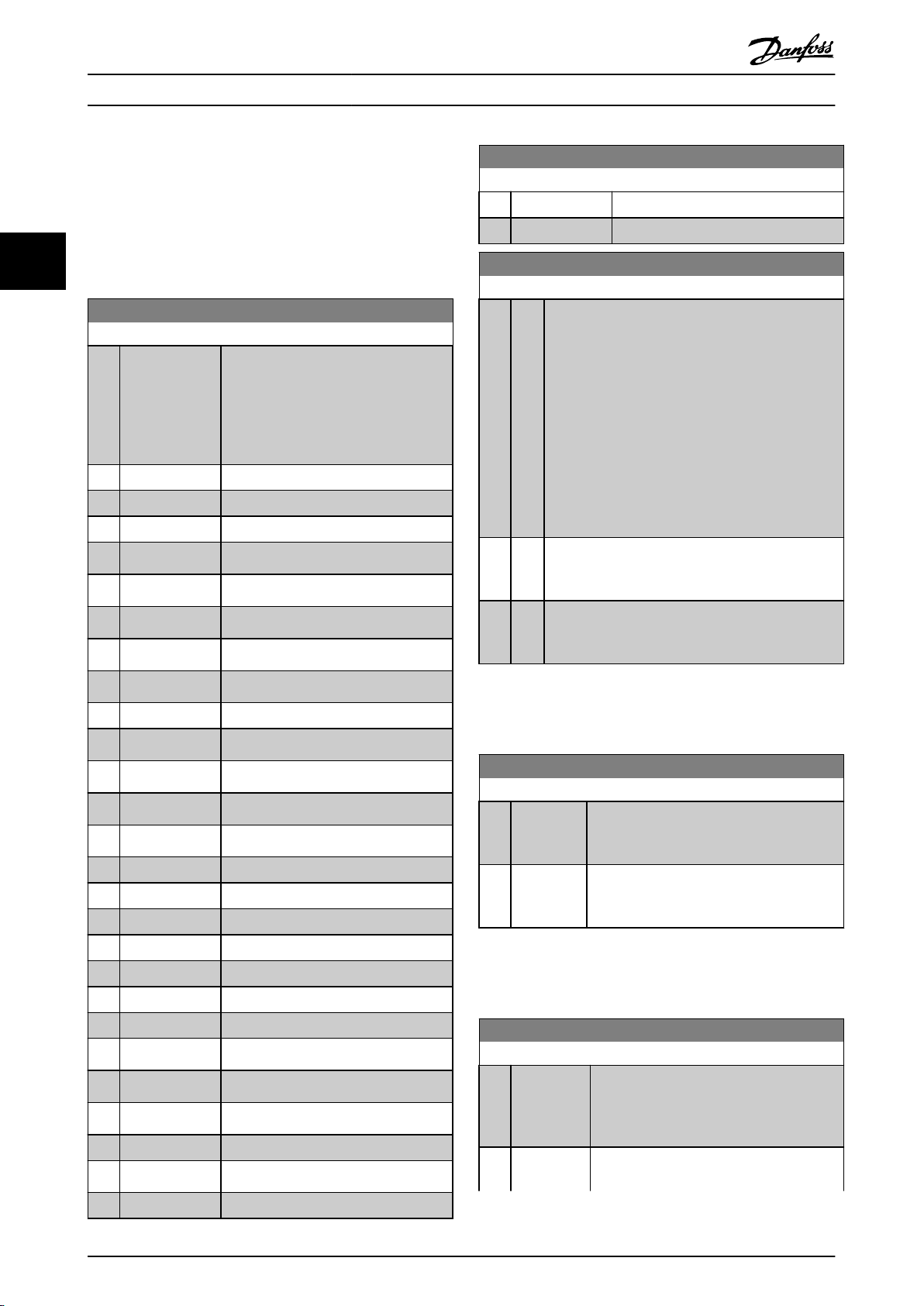
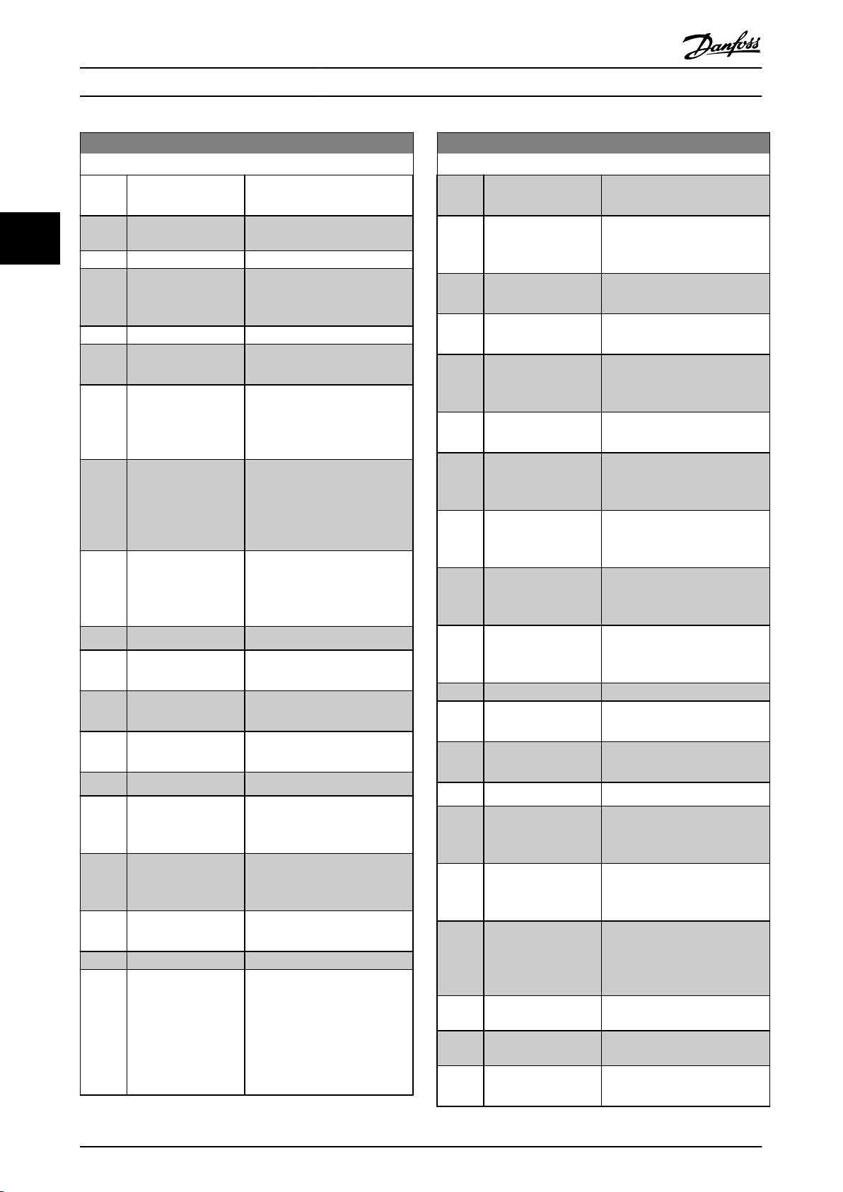
1.1.3 Definitions
Frequency converter
I
VLT,
Maximum output current.
a situation that may result in equipment or
highlighted information that should be regarded
MAX
I
VLT
,N
Rated output current supplied by the frequency converter.
U
VLT, MAX
Maximum output voltage.
Input
Control command
and stop the connected motor by means of LCP and
Start
digital inputs.
Functions are divided into two groups.
Functions in group 1 have higher priority than functions in
group 2.
Group 1 Reset, Coasting stop, Reset and Coasting stop,
Quick-stop,
Group 2 Start, Pulse start, Reversing, Start reversing, Jog
and
Table 1.3
DC braking, Stop and the [OFF] key.
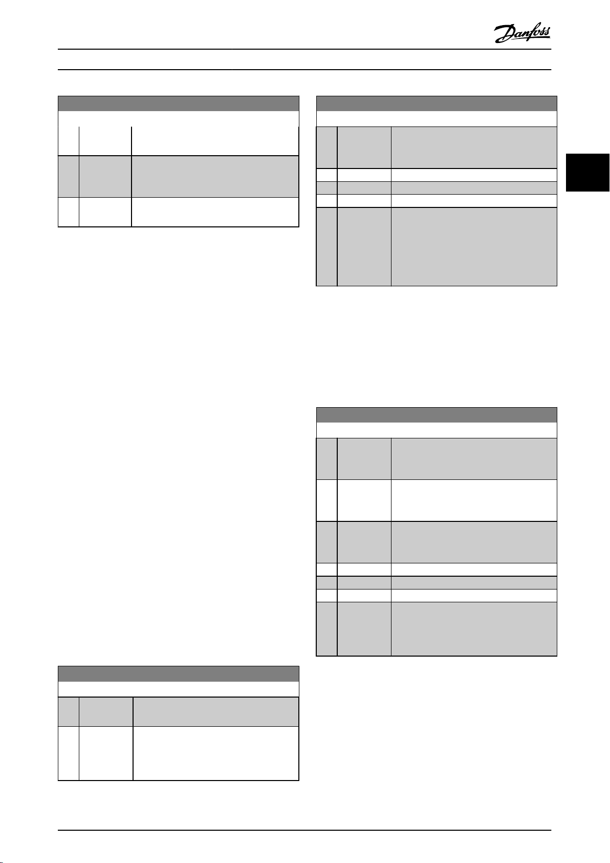
Freeze output
Motor
Motor Running
Torque
generated on output shaft and speed from zero
rpm to max. speed on motor.
f
JOG
Motor frequency when the jog function is activated (via
digital terminals).
f
M
Motor frequency.
f
MAX
Maximum motor frequency.
f
MIN
Minimum motor frequency.
f
M,N
Rated motor frequency (nameplate data).
I
M
Motor current (actual).
I
M,N
Rated motor current (nameplate data).
n
M,N
Rated motor speed (nameplate data).
n
s
Synchronous motor speed
2 ×
par
=
. 1 − 23 × 60
par
. 1 − 39
n
s
n
slip
s
Motor slip.
P
M,N
Rated motor power (nameplate data in kW or HP).
1 1
MG33MF02 - VLT® is a registered Danfoss trademark
3
Page 5
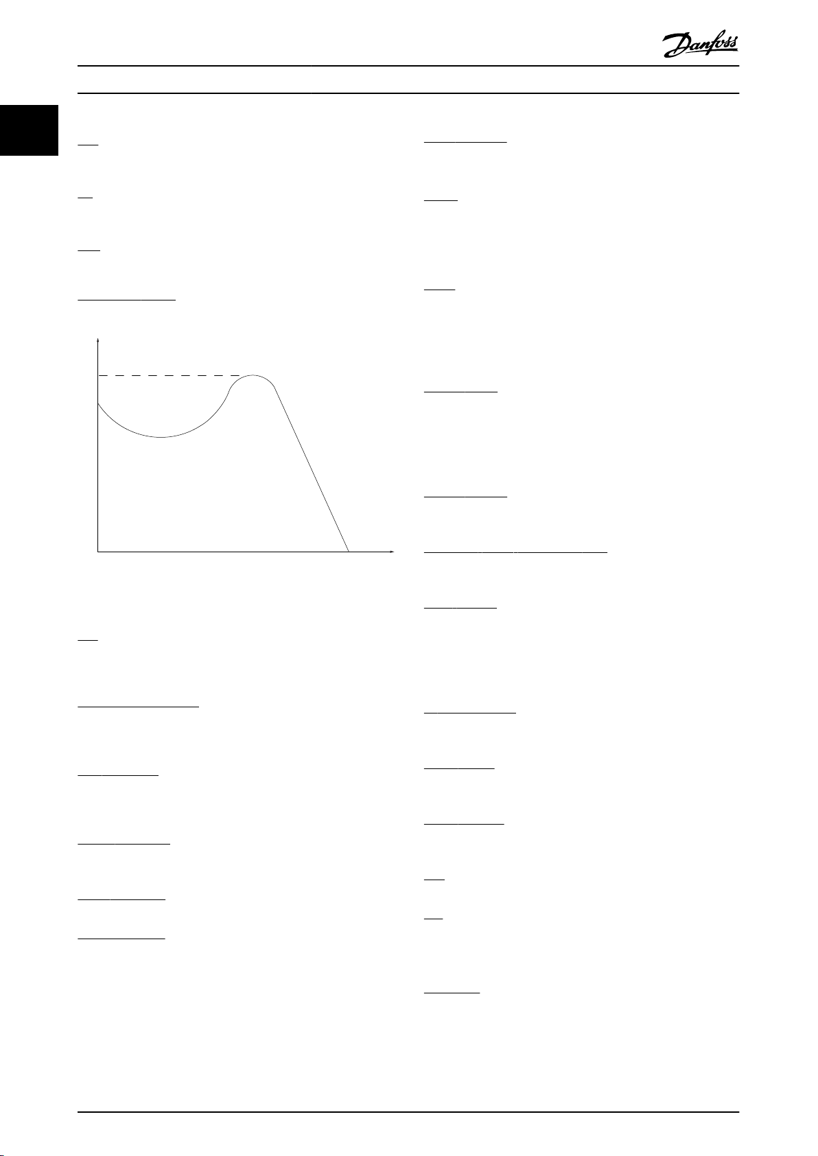
175ZA078.10
Pull-out
rpm
Torque
Introduction
VLT® AutomationDrive Programming Guide
11
T
M,N
Rated torque (motor).
Pulse Reference
pulse frequency signal transmitted to the digital inputs
A
(terminal 29 or 33).
U
M
Instantaneous motor voltage.
U
M,N
Rated motor voltage (nameplate data).
Break-away torque
Ref
MAX
Determines the relationship between the reference input
at
100% full scale value (typically 10 V, 20 mA) and the
resulting reference. The maximum reference value set in
3-03 Maximum Reference.
Ref
MIN
Determines the relationship between the reference input
0% value (typically 0 V, 0 mA, 4 mA) and the resulting
at
reference. The minimum reference value set in
3-02 Minimum Reference.
Miscellaneous
Analog Inputs
analog inputs are used for controlling various
The
functions of the frequency converter.
There are two types of analog inputs:
Current input, 0-20 mA and 4-20 mA
Voltage input, -10 to +10 V DC.
Analog Outputs
analog outputs can supply a signal of 0-20 mA, 4-20
The
mA.
Automatic Motor Adaptation, AMA
algorithm determines the electrical parameters for
AMA
Illustration 1.1
the connected motor at standstill.
Brake Resistor
brake resistor is a module capable of absorbing the
η
VLT
The efficiency of the frequency converter is defined as the
between the power output and the power input.
ratio
The
brake power generated in regenerative braking. This
regenerative braking power increases the intermediate
circuit voltage and a brake chopper ensures that the
power is transmitted to the brake resistor.
Start-disable command
stop command belonging to the group 1 control
A
commands - see this group.
Stop command
See
Control commands.
References
Analog Reference
A
signal transmitted to the analog inputs 53 or 54, can be
voltage or current.
Binary Reference
A
signal transmitted to the serial communication port.
Preset Reference
A
defined preset reference to be set from -100% to +100%
of the reference range. Selection of eight preset references
via the digital terminals.
CT Characteristics
Constant
torque characteristics used for all applications
such as conveyor belts, displacement pumps and cranes.
Digital Inputs
digital inputs can be used for controlling various
The
functions of the frequency converter.
Digital Outputs
frequency converter features two Solid State outputs
The
that can supply a 24 V DC (max. 40 mA) signal.
DSP
Signal Processor.
Digital
ETR
Electronic
Thermal Relay is a thermal load calculation
based on present load and time. Its purpose is to estimate
the motor temperature.
Hiperface
Hiperface®
®
is a registered trademark by Stegmann.
4 MG33MF02 - VLT® is a registered Danfoss trademark
Page 6

Introduction
VLT® AutomationDrive Programming Guide
Initialising
initialising is carried out (14-22 Operation Mode), the
If
frequency converter returns to the default setting.
Intermittent Duty Cycle
An intermittent duty rating refers to a sequence of duty
cycles. Each cycle consists of an on-load and an off-load
period. The operation can be either periodic duty or nonperiodic duty.
LCP
The Local Control Panel makes up a complete interface for
control and programming of the frequency converter. The
control panel is detachable and can be installed up to 3 m
from the frequency converter, i.e. in a front panel with the
installation kit option.
lsb
Least significant bit.
msb
Most significant bit.
MCM
Short for Mille Circular Mil, an American measuring unit for
cable cross-section. 1 MCM = 0.5067mm2.
On-line/Off-line Parameters
Changes
after the data value is changed. Changes to off-line
parameters are not activated until you enter [OK] on the
LCP.
Process PID
The
temperature, etc. by adjusting the output frequency to
match the varying load.
PCD
Process
Power Cycle
Switch
power on again.
Pulse Input/Incremental Encoder
An
information on motor speed. The encoder is used in
applications where great accuracy in speed control is
required.
RCD
Residual
Set-up
You
between the four parameter Set-ups and edit one Set-up,
while another Set-up is active.
SFAVM
Switching
Vector Modulation (14-00
to on-line parameters are activated immediately
PID control maintains the desired speed, pressure,
Control Data
off the mains until display (LCP) is dark – then turn
external, digital pulse transmitter used for feeding back
Current Device.
can save parameter settings in four Set-ups. Change
pattern called
Stator Flux oriented Asynchronous
Switching Pattern).
Slip Compensation
frequency converter compensates for the motor slip
The
by giving the frequency a supplement that follows the
measured motor load keeping the motor speed almost
constant.
Smart Logic Control (SLC)
SLC is a sequence of user defined actions executed
The
when the associated user defined events are evaluated as
true by the Smart Logic Controller. (Parameter group 13-**
Smart Logic Control (SLC).
STW
Status Word
FC Standard Bus
Includes RS-485 bus with FC protocol or MC protocol. See
8-30 Protocol.
Thermistor
temperature-dependent resistor placed where the
A
temperature is to be monitored (frequency converter or
motor).
Trip
state entered in fault situations, e.g. if the frequency
A
converter is subject to an over-temperature or when the
frequency converter is protecting the motor, process or
mechanism. Restart is prevented until the cause of the
fault has disappeared and the trip state is cancelled by
activating reset or, in some cases, by being programmed
to reset automatically. Trip may not be used for personal
safety.
Trip Locked
state entered in fault situations when the frequency
A
converter is protecting itself and requiring physical
intervention, e.g. if the frequency converter is subject to a
short circuit on the output. A locked trip can only be
cancelled by cutting off mains, removing the cause of the
fault, and reconnecting the frequency converter. Restart is
prevented until the trip state is cancelled by activating
reset or, in some cases, by being programmed to reset
automatically. Trip may not be used for personal safety.
VT Characteristics
Variable
VVC
If
Voltage Vector Control (VVC
and the stability, both when the speed reference is
changed and in relation to the load torque.
60° AVM
Switching
Modulation (14-00
Power Factor
The
torque characteristics used for pumps and fans.
plus
compared with standard voltage/frequency ratio control,
pattern called 60°
Switching Pattern).
power factor is the relation between I1 and I
plus
) improves the dynamics
Asynchronous Vector
RMS
.
1 1
MG33MF02 - VLT® is a registered Danfoss trademark
5
Page 7
Introduction
x U x I
cos
11
Power factor
=
3
x U x I
3
1
ϕ
RMS
The power factor for 3-phase control:
VLT® AutomationDrive Programming Guide
7. Please note that the frequency converter has
voltage sources than L1, L2 and L3, when
more
load sharing (linking of DC intermediate circuit)
or external 24 V DC are installed. Check that all
=
I1 x cos
I
RMS
ϕ1
=
I
RMS
I
1
since cos
ϕ1 = 1
The power factor indicates to which extent the frequency
converter imposes a load on the mains supply.
The lower the power factor, the higher the I
RMS
for the
same kW performance.
I
RMS
=
I
+
1
2
I
+
I
+ .. +
5
7
2
I
n
2
2
In addition, a high power factor indicates that the different
harmonic
currents are low.
The frequency converters' built-in DC coils produce a high
power factor, which minimizes the imposed load on the
mains supply.
Warning against unintended start
voltage sources have been disconnected and that
the necessary time has elapsed before
commencing repair work.
1. The motor can be brought to a stop by means of
digital commands, bus commands, references or
a local stop, while the frequency converter is
connected to mains. If personal safety considerations (e.g. risk of personal injury caused by
contact with moving machine parts following an
unintentional start) make it necessary to ensure
that no unintended start occurs, these stop
functions are not sufficient. In such cases the
mains supply must be disconnected or the Safe
WARNING
The voltage of the frequency converter is dangerous
whenever
motor, frequency converter or fieldbus may cause death,
serious personal injury or damage to the equipment.
Consequently, the instructions in this manual, as well as
national and local rules and safety regulations, must be
complied with.
Safety Regulations
connected to mains. Incorrect installation of the
1.
The mains supply to the frequency converter
must be disconnected whenever repair work is to
be carried out. Check that the mains supply has
been disconnected and that the necessary time
has elapsed before removing motor and mains
supply plugs.
2. [Off] does not disconnect the mains supply and
consequently it must not be used as a safety
switch.
3. The equipment must be properly earthed, the
user must be protected against supply voltage
and the motor must be protected against
overload in accordance with applicable national
NOTE
When using the Safe Stop function, always follow the
instructions in the section Safe Stop of the Design Guide.
Stop function must be activated.
2. The motor may start while setting the
parameters. If this means that personal safety
may be compromised (e.g. personal injury caused
by contact with moving machine parts), motor
starting must be prevented, for instance by use
of the Safe Stop function or secure disconnection
of the motor connection.
3. A motor that has been stopped with the mains
supply connected, may start if faults occur in the
electronics of the frequency converter, through
temporary overload or if a fault in the power
supply grid or motor connection is remedied. If
unintended start must be prevented for personal
safety reasons (e.g. risk of injury caused by
contact with moving machine parts), the normal
stop functions of the frequency converter are not
sufficient. In such cases the mains supply must be
disconnected or the Safe Stop function must be
activated.
and local regulations.
4. The earth leakage current exceeds 3.5 mA.
5. Protection against motor overload is not included
in the factory setting. If this function is desired,
set 1-90 Motor Thermal Protection to data value
ETR trip 1 [4] or data value ETR warning 1 [3].
6. Do not remove the plugs for the motor and
mains supply while the frequency converter is
4. Control signals from, or internally within, the
frequency
converter may in rare cases be
activated in error, be delayed or fail to occur
entirely. When used in situations where safety is
critical, e.g. when controlling the electromagnetic
brake function of a hoist application, these
control signals must not be relied on exclusively.
connected to mains. Check that the mains supply
has been disconnected and that the necessary
time has elapsed before removing motor and
mains plugs.
6 MG33MF02 - VLT® is a registered Danfoss trademark
Page 8

Introduction
VLT® AutomationDrive Programming Guide
WARNING
High Voltage
Touching
equipment has been disconnected from mains.
Also make sure that other voltage inputs have been
disconnected, such as external 24 V DC, load sharing
(linkage of DC intermediate circuit), as well as the motor
connection for kinetic back up.
Systems where frequency converters are installed must, if
necessary, be equipped with additional monitoring and
protective devices according to the valid safety regulations,
e.g law on mechanical tools, regulations for the prevention
of accidents etc. Modifications on the frequency converters
by means of the operating software are allowed.
NOTE
Hazardous
builder/ integrator who is responsible for taking necessary
preventive means into consideration. Additional
monitoring and protective devices may be included, always
according to valid national safety regulations, e.g. law on
mechanical tools, regulations for the prevention of
accidents.
the electrical parts may be fatal - even after the
situations shall be identified by the machine
1 1
NOTE
Lifts and Hoists:
Crane,
The controlling of external brakes must always have a
redundant system. The frequency converter can in no
circumstances be the primary safety circuit. Comply with
relevant standards, e.g.
Hoists and cranes: IEC 60204-32
Lifts: EN 81
Protection Mode
a hardware limit on motor current or dc-link voltage
Once
is exceeded the frequency converter will enter “Protection
mode”. “Protection mode” means a change of the PWM
modulation strategy and a low switching frequency to
minimize losses. This continues 10 s after the last fault and
increases the reliability and the robustness of the
frequency converter while re-establishing full control of the
motor.
In hoist applications “Protection mode” is not usable
because the frequency converter will usually not be able to
leave this mode again and therefore it will extend the time
before activating the brake – which is not recommendable.
The “Protection mode” can be disabled by setting
14-26 Trip Delay at Inverter Fault to zero which means that
the frequency converter will trip immediately if one of the
hardware limits is exceeded.
NOTE
is recommended to disable protection mode in hoisting
It
applications (14-26 Trip Delay at Inverter Fault = 0)
MG33MF02 - VLT® is a registered Danfoss trademark
7
Page 9
3 Phase
power
input
DC bus
Switch Mode
Power Supply
Motor
Analog Output
Interface
relay1
* relay2
ON=Terminated
OFF=Open
Brake
resistor
130BC931.10
91 (L1)
92 (L2)
93 (L3)
PE
88 (-)
89 (+)
50 (+10 V OUT)
53 (A IN)
54 (A IN)
55 (COM A IN)
0/4-20 mA
12 (+24V OUT)
13 (+24V OUT)
37 (D IN)
18 (D IN)
20 (COM D IN)
10Vdc
15mA 130/200mA
+ - + -
(U) 96
(V) 97
(W) 98
(PE) 99
(COM A OUT) 39
(A OUT) 42
(P RS-485) 68
(N RS-485) 69
(COM RS-485) 61
0V
5V
S801
0/4-20 mA
RS-485
RS-485
03
+10Vdc
0/-10Vdc -
+10Vdc
+10Vdc
0/4-20 mA
0/-10Vdc -
240Vac, 2A
24Vdc
02
01
05
04
06
240Vac, 2A
24V (NPN)
0V (PNP)
0V (PNP)
24V (NPN)
19 (D IN)
24V (NPN)
0V (PNP)
27
24V
0V
(D IN/OUT)
0V (PNP)
24V (NPN)
(D IN/OUT)
0V
24V
29
24V (NPN)
0V (PNP)
0V (PNP)
24V (NPN)
33 (D IN)
32 (D IN)
1 2
ON
S201
ON
21
S202
ON=0/4-20mA
OFF=0/-10Vdc +10Vdc
95
400Vac, 2A
P 5-00
21
ON
S801
(R+) 82
(R-) 81
*
*
: Chassis
: Earth
**
Introduction
VLT® AutomationDrive Programming Guide
11
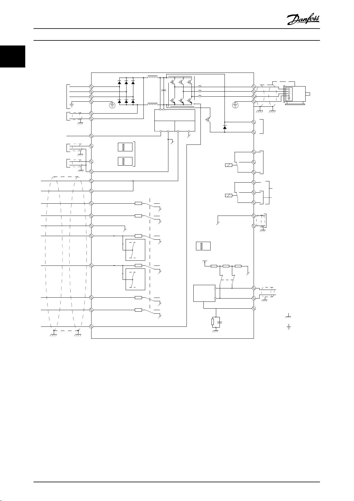
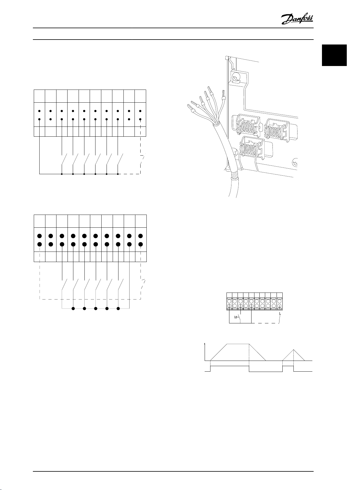
1.1.4 Electrical Wiring - Control Cables
Illustration 1.2 Basic Wiring Schematic Drawing.
A=Analog, D=Digital
Terminal
* Terminal 37 is not included in FC 301 (except frame size A1). Relay 2 and terminal 29 have no function in FC 301.
** Do not connect cable screen.
Very long control cables and analog signals may in rare cases and depending on installation result in 50/60 Hz earth loops
37 is used for Safe Stop. For Safe Stop installation instructions, refer to the Design Guide.
due to noise from mains supply cables.
If this occurs, it may be necessary to break the screen or insert a 100 nF capacitor between screen and chassis.
The digital and analog inputs and outputs must be connected separately to the common inputs (terminal 20, 55, 39) of the
frequency converter to avoid ground currents from both groups to affect other groups. For example, switching on the
digital input may disturb the analog input signal.
8 MG33MF02 - VLT® is a registered Danfoss trademark
Page 10
12 13 18 19 27 29 32 33 20 37
+24 VDC
0 VDC
130BT106.10
PNP (Source)
Digital input wiring
NPN (Sink)
Digital input wiring
12 13 18 19 27 29 32 33 20 37
+24 VDC
0 VDC
130BT107.11
130BA681.10
12 13 18 37
130BA155.12
322719 29 33 20
P 5-12 [0]
P 5-10 [8]
Start/Stop
+24V
Speed
Safe Stop
Start/Stop
[18]
Introduction
VLT® AutomationDrive Programming Guide
Input polarity of control terminals
Illustration 1.3
1 1
Illustration 1.5
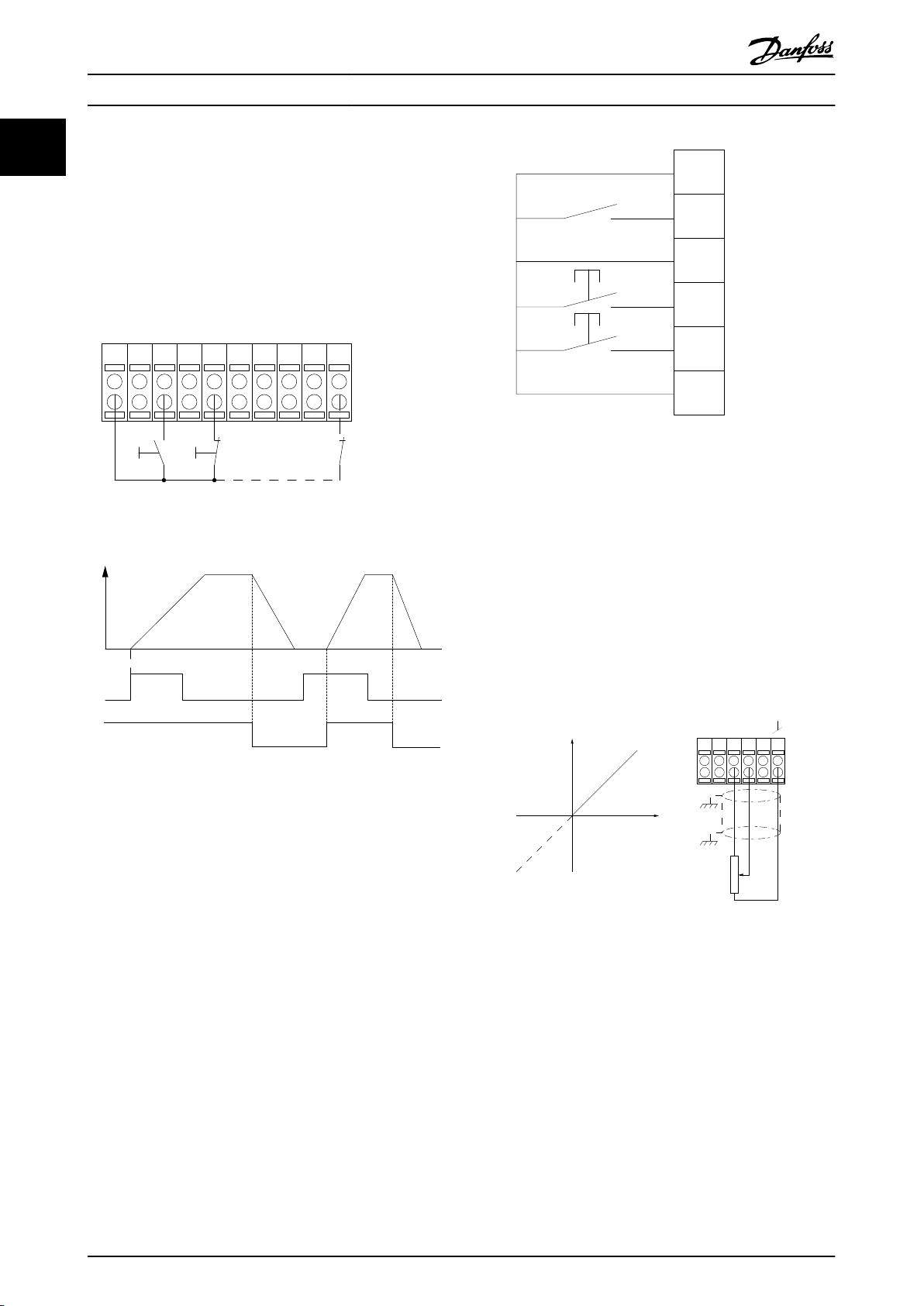
1.1.5 Start/Stop
Illustration 1.4
NOTE
Control cables must be screened/armoured.
See section on earthing of screened/armoured control
in the Design Guide for the correct termination of
cables
control cables.
Terminal 18 = 5-10
Terminal 18 Digital Input [8] Start
Terminal 27 = 5-12 Terminal 27 Digital Input [0] No
operation (Default coast inverse)
Terminal 37 = Safe stop (where available)
Illustration 1.6
MG33MF02 - VLT® is a registered Danfoss trademark
9
Page 11
12 13 18 37
130BA156.12
322719 29 33 20
P 5 - 12 [6]
P 5 - 10[9]
+24V
Speed
Start Stop inverse Safe Stop
Start (18)
Start (27)
12
18
27
29
32
37
+24V
Par. 5-10
Par. 5-12
Par. 5-13
Par. 5-14
130BA021.12
130BA154.11
555039 42 53 54
Speed RPM
P 6-15
1 kΩ
+10V/30mA
Ref. voltage
P 6-11 10V
Introduction
VLT® AutomationDrive Programming Guide
11
1.1.6 Pulse Start/Stop
Terminal 18 = 5-10
Terminal 18 Digital InputLatched start,
[9]
Terminal 27= 5-12 Terminal 27 Digital InputStop inverse, [6]
Terminal 37 = Safe stop (where available)
Illustration 1.8
1.1.8 Potentiometer Reference
Voltage reference via a potentiometer
Reference
Terminal 53, Low Voltage = 0 V
Terminal 53, High Voltage = 10 V
Terminal 53, Low Ref./Feedback = 0 RPM
Terminal 53, High Ref./Feedback = 1500 RPM
Switch S201 = OFF (U)
Source 1 = [1] Analog input 53 (default)
Illustration 1.7
1.1.7 Speed Up/Down
Terminals 29/32 = Speed up/down
Terminal
[9] (default)
Terminal 27 = 5-12 Terminal 27 Digital Input
Freeze reference [19]
Terminal 29 = 5-13 Terminal 29 Digital Input
Speed up [21]
Terminal 32 = 5-14 Terminal 32 Digital Input
Speed down [22]
NOTE
29 only in FC x02 (x=series type).
Terminal
18 = 5-10 Terminal 18 Digital Input Start
Illustration 1.9
10 MG33MF02 - VLT® is a registered Danfoss trademark
Page 12
Auto
on
Reset
Hand
on
O
Status
Quick
Menu
Main
Menu
Alarm
Log
Back
Cancel
Info
OK
Status
1(0)
1234rpm 10,4A 43,5Hz
Run OK
43,5Hz
On
Alarm
Warn.
130BA018.13
1
2
3
4
b
a
c
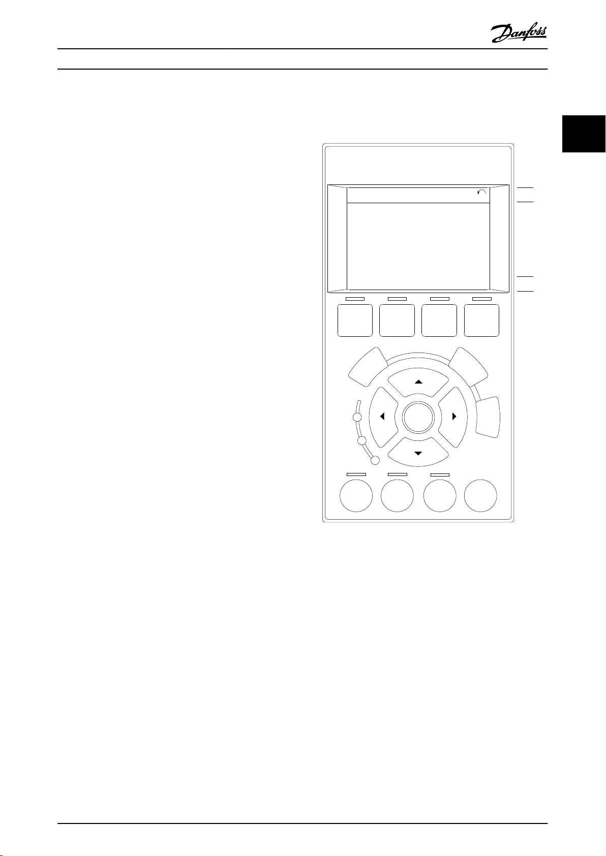
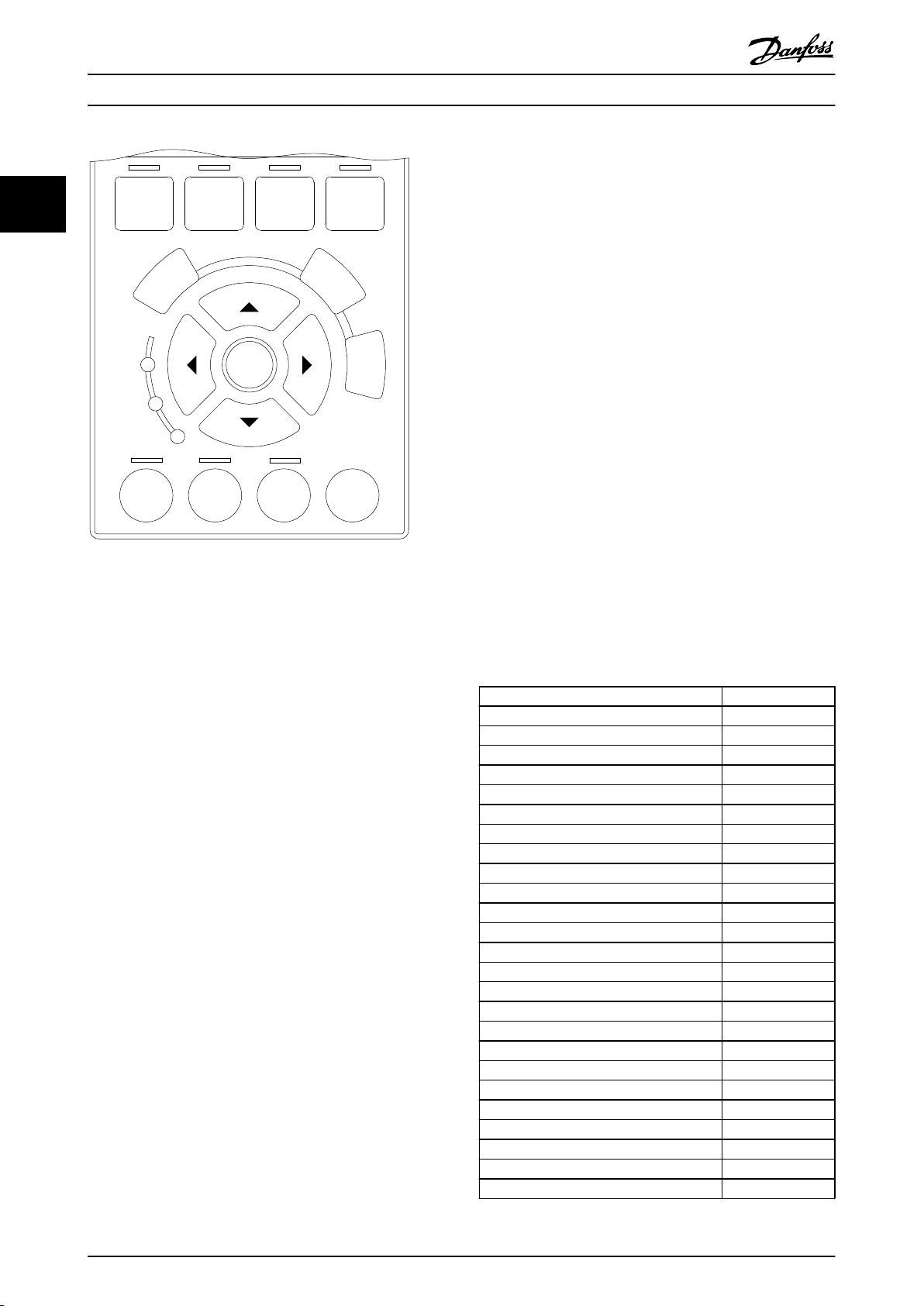
How to Programme
VLT® AutomationDrive Programming Guide
2 How to Programme
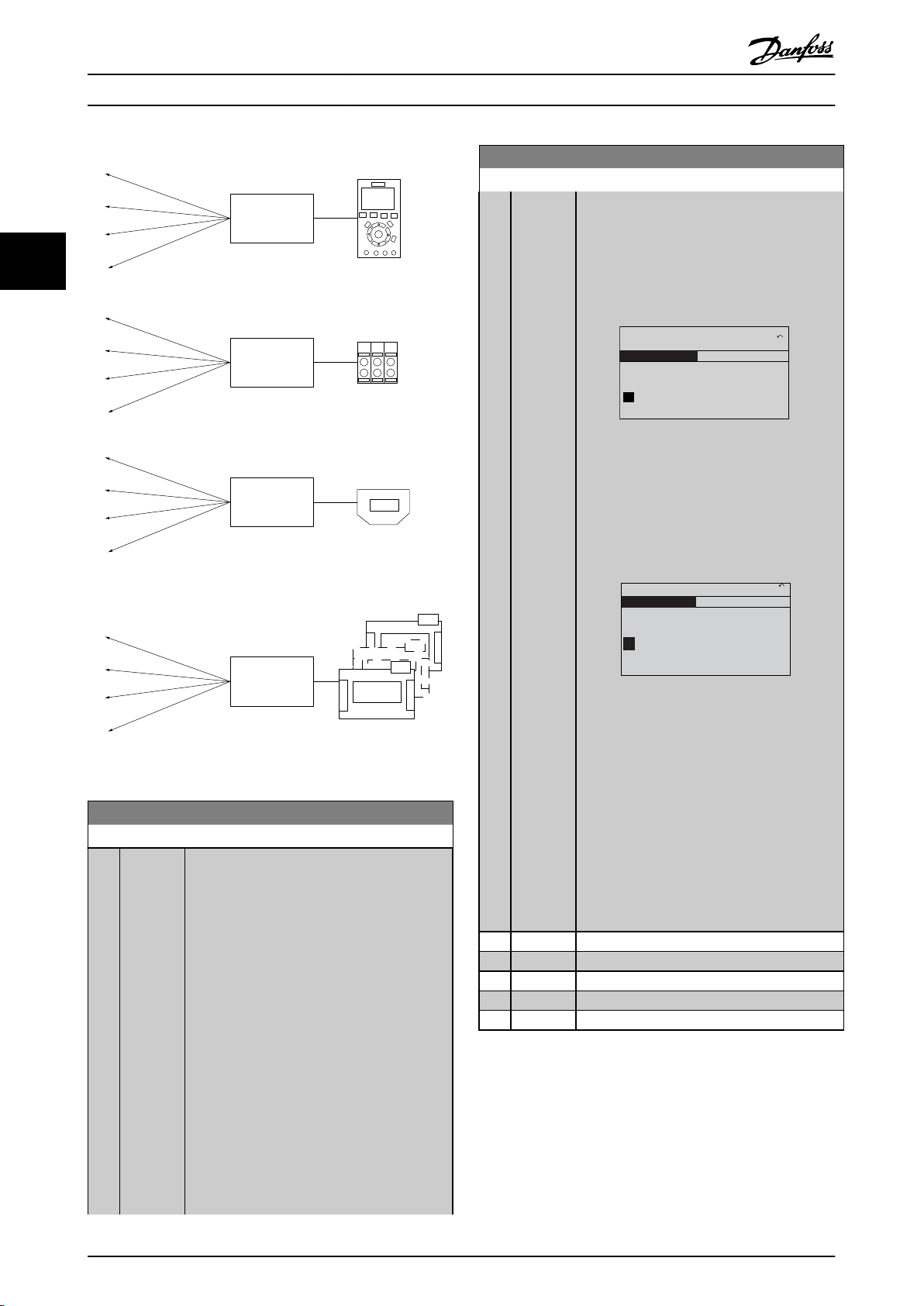
2.1 The Graphical and Numerical Local
Control Panels
The easiest programming of the frequency converter is
performed
to consult the frequency converter Design Guide, when
using the Numeric Local Control Panel (LCP 101).
The control panel is divided into four functional groups
All data is displayed in a graphical LCP display, which can
show up to five items of operating data while displaying
[Status].
by the Graphical LCP (LCP 102). It is necessary
1. Graphical display with Status lines.
2. Menu keys and indicator lights - changing
parameters and switching between display
functions.
3. Navigation keys and indicator lights (LEDs).
4. Operation keys and indicator lights (LEDs).
2 2
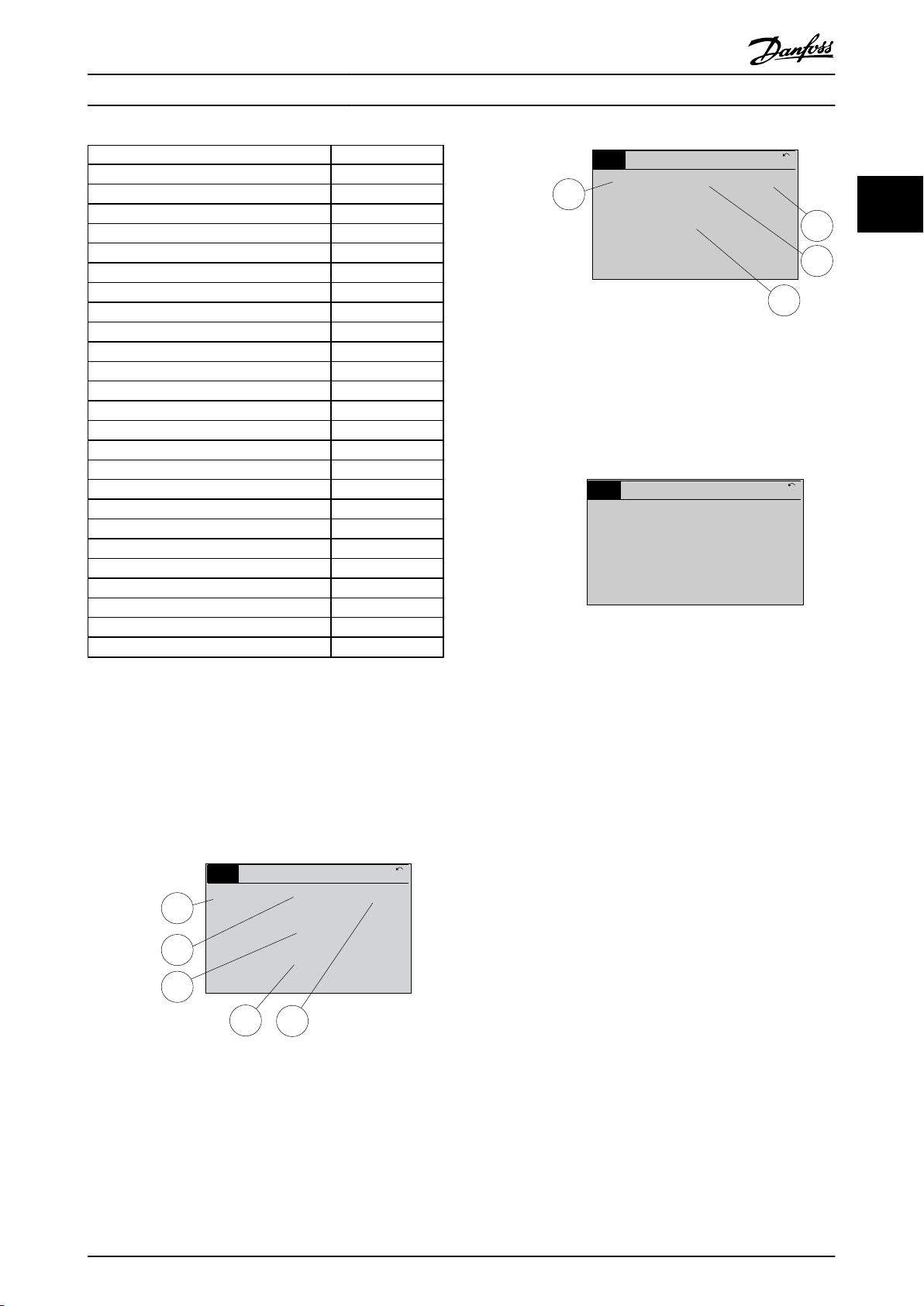
Display lines
a. Status line: Status messages displaying icons and
graphic.
b. Line 1-2: Operator data lines displaying data
defined or chosen by the user. By pressing
[Status], up to one extra line can be added.
c. Status line: Status messages displaying text.
Illustration 2.1
MG33MF02 - VLT® is a registered Danfoss trademark
11
Page 13
Top section
Middle section
Bottom section
Status
43 RPM
1.4 Hz
Auto Remote Running
! Pwr.card temp (W29)
2.9%
5.44 A 25.3kW
1(1)
130BP074.10
!
On
Warn.
Alarm
130BP044.10
130BP045.10
Status
Quick
Menu
Main
Menu
Alarm
Log
How to Programme
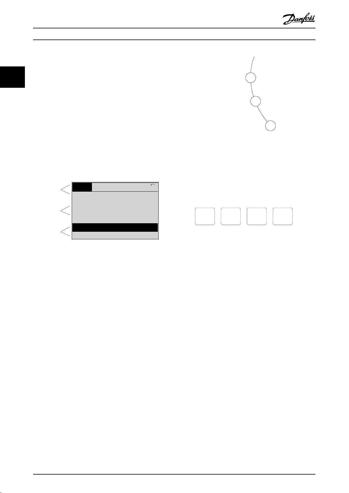
2.1.1 The LCD-Display
VLT® AutomationDrive Programming Guide
22
The LCD-display has back light and a total of 6 alphanumeric
rotation (arrow), the chosen Set-up as well as the
programming Set-up. The display is divided into 3 sections.
Top section shows up to 2 measurements in normal
operating status.
The top line in the Middle section shows up to 5
measurements with related unit, regardless of status
(except in the case of alarm/warning).
Bottom section always shows the state of the frequency
converter in Status mode.
lines. The display lines show the direction of
Illustration 2.3
Keys
LCP
The control keys are divided into functions. The keys
below the display and indicator lamps are used for
parameter Set-up, including choice of display indication
during normal operation.
Illustration 2.4
Illustration 2.2
[Status]
and/or the motor. Choose between 3 different readouts by
The Active Set-up (selected as the Active Set-up in
Active Set-up) is shown. When programming another
0-10
Set-up than the Active Set-up, the number of the
programmed Set-up appears to the right.
Display contrast adjustment
Press [Status] and [▲] for darker display
Press [Status] and [▼] for brighter display
Most parameter set-ups can be changed immediately via
the LCP, unless a password has been created via 0-60 Main
Menu Password or via 0-65 Quick Menu Password.
Indicator lights (LEDs)
If certain threshold values are exceeded, the alarm and/or
warning LED lights up. A status and alarm text appear on
the LCP.
The ON LED is activated when the frequency converter
receives mains voltage or via a DC bus terminal or 24 V
external supply. At the same time, the back light is on.
Green LED/On: Control section is working.
•
•
•
12 MG33MF02 - VLT® is a registered Danfoss trademark
Yellow LED/Warn.: Indicates a warning.
Flashing Red LED/Alarm: Indicates an alarm.
pressing the [Status] key: 5 line readouts, 4 line readouts
or Smart Logic Control.
Use [Status] for selecting the mode of display or for
changing back to Display mode from either the Quick
Menu mode, the Main Menu mode or Alarm mode. Also
use the [Status] key to toggle single or double read-out
mode.
[Quick Menu] allows quick access to different Quick Menus
such as
Use [Quick Menu] for programming the parameters
belonging to the Quick Menu. It is possible to switch
directly between Quick Menu mode and Main Menu mode.
[Main Menu] is used for programming all parameters.
It is possible to switch directly between Main Menu mode
and Quick Menu mode.
Parameter shortcut can be carried out by pressing down
the [Main Menu] key for 3 seconds. The parameter shortcut
allows direct access to any parameter.
indicates the status of the frequency converter
My Personal Menu
•
Quick Set-up
•
Changes Made
•
Loggings
•
Page 14

B
a
c
k
C
a
n
c
e
l
I
n
f
o
130BP046.10
Hand
on
O
Auto
on
Reset
How to Programme
VLT® AutomationDrive Programming Guide
[Alarm Log]
displays an Alarm list of the five latest alarms
(numbered A1-A5). To obtain additional details about an
alarm, use the arrow keys to manoeuvre to the alarm
number and press [OK]. Information is displayed about the
condition of the frequency converter before it enters the
alarm mode.
[Back] reverts to the previous step or layer in the
navigation structure.
[Cancel] last change or command will be cancelled as long
as the display has not been changed.
[Info] supplies information about a command, parameter,
or function in any display window. [Info] provides detailed
information whenever help is needed.
Exit info mode by pressing either [Info], [Back], or [Cancel].
Illustration 2.5
[Hand On]
enables control of the frequency converter via
the LCP. [Hand On] also starts the motor, and it is now
possible to enter the motor speed data by means of the
arrow keys. The key can be selected as [1] Enable or [0]
Disable via 0-40 [Hand on] Key on LCP
External stop signals activated by means of control signals
or a serial bus will override a “start” command via the LCP.
The following control signals will still be active when
[Hand On] is activated
[Hand on] - [Off] - [Auto On]
•
Reset
•
Coasting stop inverse
•
Reversing
•
Set-up select bit 0- Set-up select bit 1
•
Stop command from serial communication
•
Quick stop
•
DC brake
•
[Off] stops the connected motor. The key can be selected
as [1] Enable or [0] Disable via 0-41 [Off] Key on LCP. If no
external stop function is selected and the [Off] key is
inactive the motor can be stopped by disconnecting the
voltage.
2 2
Illustration 2.6
Illustration 2.7
Navigation Keys
The
four navigation keys are used to navigate between the
different choices available in [Quick Menu], [Main Menu]
and [Alarm Log]. Use the keys to move the cursor.
[OK] is used for choosing a parameter marked by the
cursor and for enabling the change of a parameter.
Local Control Key for local control are found at the bottom
of the LCP.
[Auto On] enables the frequency converter to be
controlled via the control terminals and/or serial communication. When a start signal is applied on the control
terminals and/or the bus, the frequency converter will
start. The key can be selected as [1] Enable or [0] Disable
via 0-42 [Auto on] Key on LCP.
NOTE
active HAND-OFF-AUTO signal via the digital inputs has
An
higher priority than the control keys [Hand On] – [Auto
On].
is used for resetting the frequency converter after
[Reset]
an alarm (trip). It can be selected as [1] Enable or [0]
Disable via 0-43 [Reset] Key on LCP.
The parameter shortcut can be carried out by holding
down the [Main Menu] key for 3 seconds. The parameter
shortcut allows direct access to any parameter.
2.1.2 Quick Transfer of Parameter Settings
between
Converters
Multiple Frequency
Once the set-up of a frequency converter is complete, we
Illustration 2.8
recommend
that you store the data in the LCP or on a PC
via MCT 10 Set-up Software Tool.
MG33MF02 - VLT® is a registered Danfoss trademark
13
Page 15
Auto
on
Reset
Hand
on
O
Status
Quick
Menu
Main
Menu
Alarm
Log
Back
Cancel
Info
OK
On
Alarm
Warn.
130BA027.10
How to Programme
VLT® AutomationDrive Programming Guide
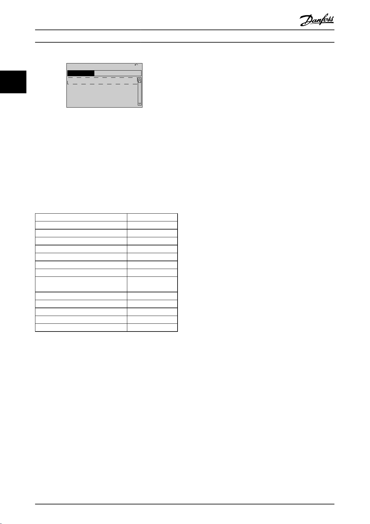
2.1.3 Display Mode
22
Illustration 2.9
storage in LCP
Data
1.
Go to 0-50 LCP Copy
2. Press the [OK] key
3. Select “All to LCP”
4. Press the [OK] key
All parameter settings are now stored in the LCP indicated
by the progress bar. When 100% is reached, press [OK].
NOTE
the motor before performing this operation.
Stop
Connect the LCP to another frequency converter and copy
parameter settings to this frequency converter as well.
the
Data transfer from LCP to frequency converter
1.
Go to 0-50 LCP Copy
3. Select “All from LCP”
2. Press the [OK] key
4. Press the [OK] key
The parameter settings stored in the LCP are now
transferred to the frequency converter indicated by the
progress bar. When 100% is reached, press [OK].
NOTE
Stop
the motor before performing this operation.
In normal operation, up to 5 different operating variables
be indicated continuously in the middle section: 1.1,
can
1.2, and 1.3 as well as 2 and 3.
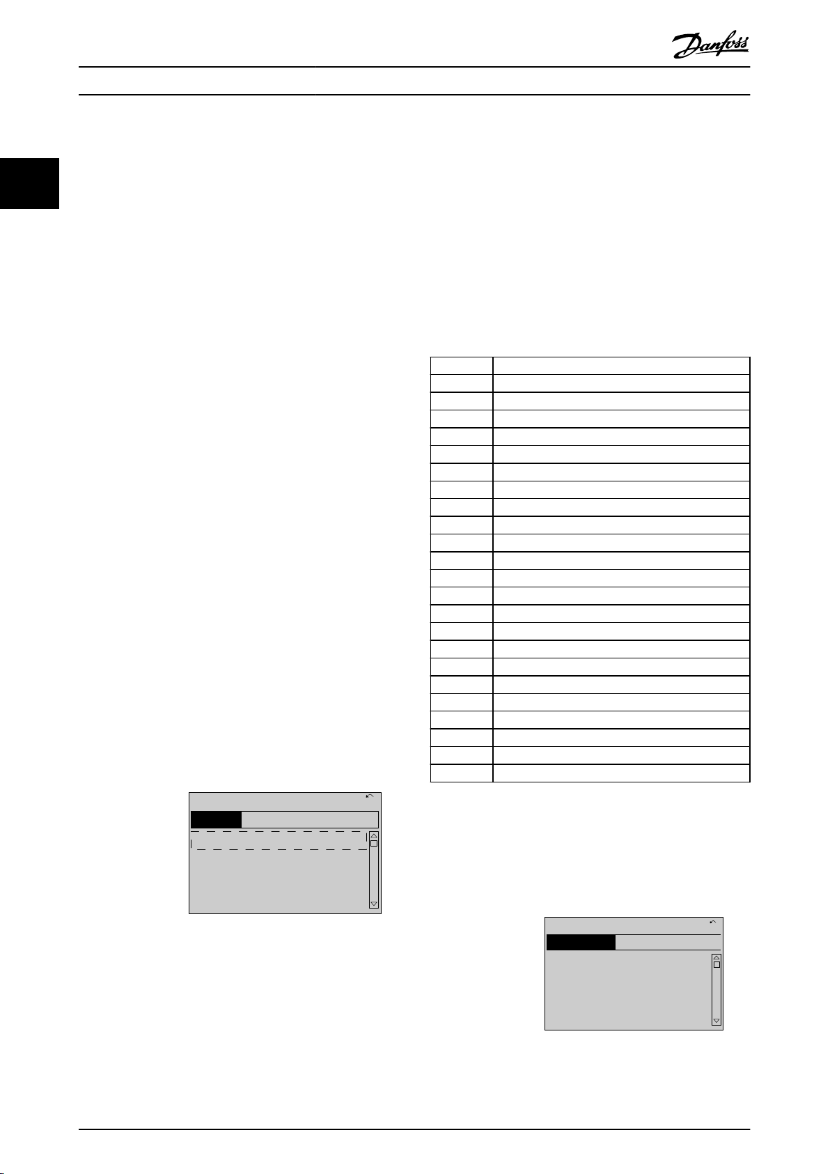
2.1.4 Display Mode - Selection of ReadOuts
It is possible to toggle between three status read-out
screens
by pressing the [Status] key.
Operating variables with different formatting are shown in
each status screen - see below.
Table 2.1 shows the measurements you can link to each of
the operating variables. When Options are mounted,
additional measurements are available. Define the links via
0-20 Display Line 1.1 Small, 0-21 Display Line 1.2 Small,
0-22 Display Line 1.3 Small, 0-23 Display Line 2 Large, and
0-24 Display Line 3 Large.
Each readout parameter selected in 0-20 Display Line 1.1
Small to 0-24 Display Line 3 Large has its own scale and
digits after a possible decimal point. By larger numeric
value of a parameter fewer digits are displayed after the
decimal point.
Ex.: Current readout 5.25A; 15.2A 105A.
Operating variable Unit
16-00 Control Word hex
16-01 Reference [Unit] [unit]
16-02 Reference [%] %
16-03 Status Word hex
16-05 Main Actual Value [%] %
16-10 Power [kW] [kW]
16-11 Power [hp] [HP]
16-12 Motor Voltage [V]
16-13 Frequency [Hz]
16-14 Motor Current [A]
16-16 Torque [Nm] Nm
16-17 Speed [RPM] [RPM]
16-18 Motor Thermal %
16-20 Motor Angle
16-30 DC Link Voltage V
16-32 Brake Energy /s kW
16-33 Brake Energy /2 min kW
16-34 Heatsink Temp. C
16-35 Inverter Thermal %
16-36 Inv. Nom. Current A
16-37 Inv. Max. Current A
16-38 SL Controller State
16-39 Control Card Temp. C
16-40 Logging Buffer Full
16-50 External Reference
14 MG33MF02 - VLT® is a registered Danfoss trademark
Page 16
1.1
2
3
1.3
1.2
130BP041.10
799 RPM
Auto Remote Ramping
1 (1)
36.4 kw7.83 A
0.000
53.2 %
Status
1.1
1.2
2
1.3
130BP062.10
207RPM
Auto Remote Running
1 (1)
24.4 kW5.25A
6.9
Hz
Status
130BP063.10
778 RPM
Auto Remote Running
1 (1)
4.0 kW0.86 A
State: 0 o 0 (o)
When: Do: -
Status
How to Programme
Operating variable Unit
16-51 Pulse Reference
16-52 Feedback [Unit] [Unit]
16-53 Digi Pot Reference
16-60 Digital Input bin
16-61 Terminal 53 Switch Setting V
16-62 Analog Input 53
16-63 Terminal 54 Switch Setting V
16-64 Analog Input 54
16-65 Analog Output 42 [mA] [mA]
16-66 Digital Output [bin] [bin]
16-67 Pulse Input #29 [Hz] [Hz]
16-68 Freq. Input #33 [Hz] [Hz]
16-69 Pulse Output #27 [Hz] [Hz]
16-70 Pulse Output #29 [Hz] [Hz]
16-71 Relay Output [bin]
16-72 Counter A
16-73 Counter B
16-80 Fieldbus CTW 1 hex
16-82 Fieldbus REF 1 hex
16-84 Comm. Option STW hex
16-85 FC Port CTW 1 hex
16-86 FC Port REF 1 hex
16-90 Alarm Word
16-92 Warning Word
16-94 Ext. Status Word
VLT® AutomationDrive Programming Guide
Illustration 2.11
screen III
Status
This state displays the event and action of the Smart Logic
Control. For further information, see section Smart Logic
Control.
Illustration 2.12
2 2
Table 2.1
Status
screen I
This read-out state is standard after start-up or initialization.
Use [INFO] to obtain information about the measurement
links to the displayed operating variables (1.1, 1.2, 1.3, 2
and 3).
See the operating variables shown in the screen below.
Illustration 2.10
Status screen II
the operating variables (1.1, 1.2, 1.3 and 2) shown in
See
the screen below.
In the example, Speed, Motor current, Motor power and
Frequency are selected as variables in the first and second.
MG33MF02 - VLT® is a registered Danfoss trademark
2.1.5 Parameter Set-Up
The frequency converter can be used for practically all
assignments,
which is why the number of parameters is
quite large. The frequency converter offers a choice
between two programming modes - a Main Menu and a
Quick Menu mode.
The former provides access to all parameters. The latter
takes the user through a few parameters making it
possible to start operating the frequency converter.
Regardless of the mode of programming, you can change
a parameter both in the Main Menu mode and in the
Quick Menu mode.
2.1.6 Quick Menu Key Functions
Pressing [Quick Menus] The list indicates the different
areas
contained in the Quick menu.
Select My Personal Menu to display the chosen personal
parameters. These parameters are selected in 0-25 My
Personal Menu. Up to 50 different parameters can be
added in this menu.
15
Page 17
130BC916.10
Q1 My Personal Menu
Q2 Quick Setup
Q4 Smart Setup
Q5 Changes Made
0RPM 0.00A 1(1)
Quick Menus
How to Programme
VLT® AutomationDrive Programming Guide
22
Illustration 2.13
Quick setup to go through a limited amount of
Select
parameters to get the motor running almost optimally. The
default setting for the other parameters considers the
desired control functions and the configuration of signal
inputs/outputs (control terminals).
The selection of parameter is effected by means of the
arrow keys. The parameters in the following table are
accessible.
Parameter Setting
0-01 Language
1-20 Motor Power [kW] [kW]
1-22 Motor Voltage [V]
1-23 Motor Frequency [Hz]
1-24 Motor Current [A]
1-25 Motor Nominal Speed [rpm]
5-12 Terminal 27 Digital Input [0] No function*
1-29 Automatic Motor Adaptation (AMA) [1] Enable complete
3-02 Minimum Reference [rpm]
3-03 Maximum Reference [rpm]
3-41 Ramp 1 Ramp up Time [sec]
3-42 Ramp 1 Ramp Down Time [sec]
3-13 Reference Site
Table 2.2
*
If terminal 27 is set to “no function”, no connection to
+24 V on terminal 27 is necessary.
Select Changes made to get information about:
the last 10 changes. Use the [▲] [▼] navigation
•
keys to scroll between the last 10 changed
parameters.
the changes made since default setting.
•
Select Loggings to get information about the display line
read-outs. The information is shown as graphs.
Only display parameters selected in 0-20 Display Line 1.1
Small and 0-24 Display Line 3 Large can be viewed. It is
possible to store up to 120 samples in the memory for
later reference.
16 MG33MF02 - VLT® is a registered Danfoss trademark
AMA
Page 18
Quick
Menu
OK
OK
OK
OK
OK
OK
OK
OK
OK
OK
OK
OK
OK
OK
How to Programme
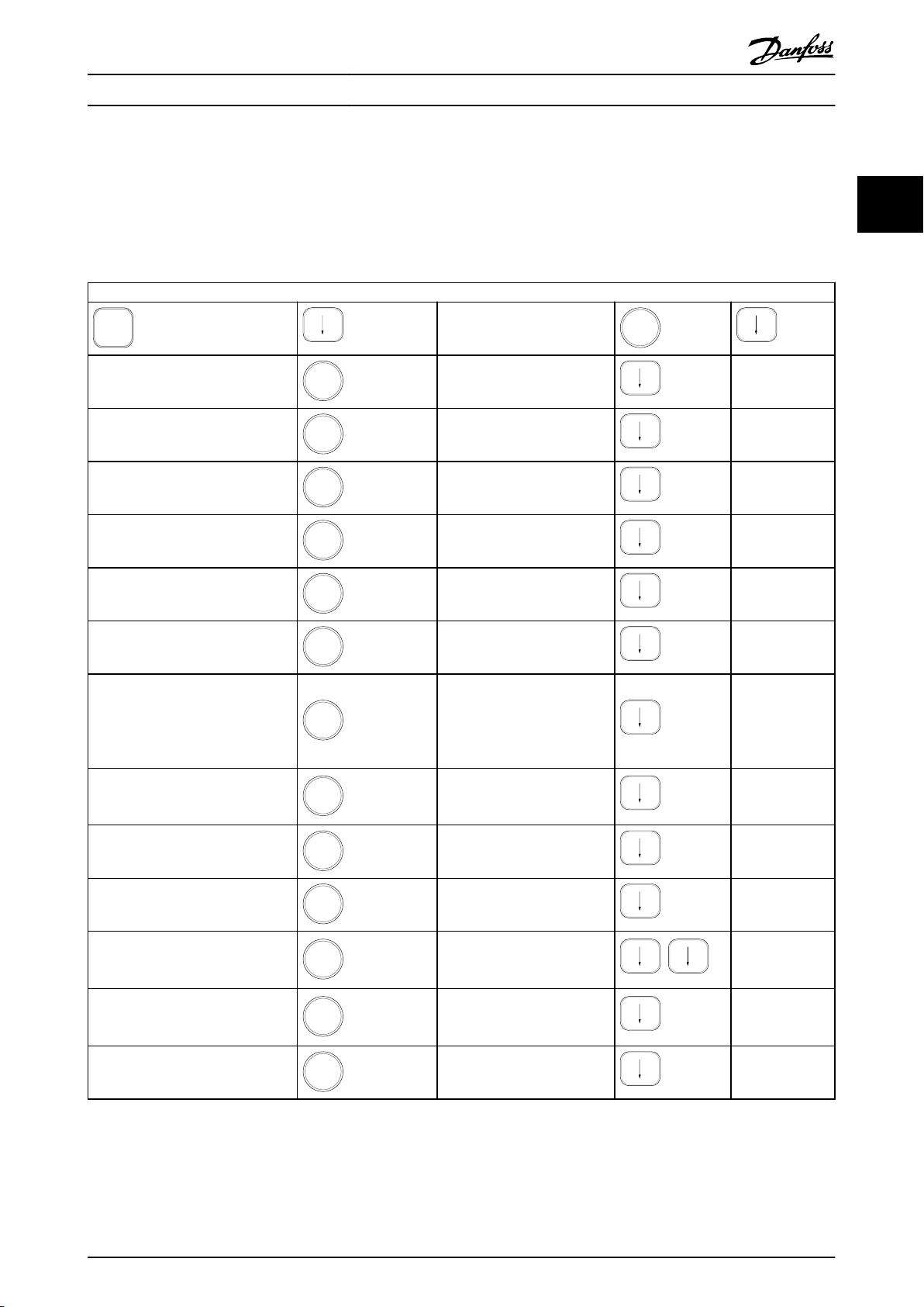
2.1.7 Initial Commissioning
VLT® AutomationDrive Programming Guide
The easiest way of carrying out the initial commissioning is
using the [Quick Menu] key and follow the quick set-up
by
procedure using LCP 102 (read Table 2.3Table 2.4 from left
to right). The example applies to open loop applications.
Press
0-01 Language
1-20 Motor Power [kW]
1-22 Motor Voltage
1-23 Motor Frequency
1-24 Motor Current
2 2
Q2 Quick Menu
Set language
Set Motor nameplate power
Set Nameplate voltage
Set Nameplate frequency
Set Nameplate current
1-25 Motor Nominal Speed
5-12 Terminal 27 Digital Input
1-29 Automatic Motor Adaptation
(AMA)
3-02 Minimum Reference
3-03 Maximum Reference
3-41 Ramp 1 Ramp up Time
3-42 Ramp 1 Ramp Down Time
3-13 Reference Site
Set Nameplate speed in RPM
If terminal default is Coast
inverse it is possible to change
this setting to No function. No
connection to terminal 27 is
then needed for running AMA
Set desired AMA function.
complete AMA is
Enable
recommended
Set the minimum speed of the
shaft
motor
Set the maximum speed of the
shaft
motor
Set the ramping up time with
reference
motor speed, n
to synchronous
s
Set the ramping down time
reference to synchronous
with
motor speed, n
s
Set the site from where the
reference
must work
Table 2.3
MG33MF02 - VLT® is a registered Danfoss trademark
17
Page 19
130BP066.10
1107 RPM
0 -
**
Operation/Display
1 -
**
Load/Motor
2 -
**
Brakes
3 -
**
Reference / Ramps
3.84 A 1 (1)
Main menu
130BP067.10
740RPM
0 -01 Language
[0] English
10.64A 1 [1]
0-0
*
Basic Settings
How to Programme
VLT® AutomationDrive Programming Guide
Another easy way of commissioning the drive is by using
Smart Application Setup (SAS), which can also be
the
found under the Quick Menu. Follow the indications on
22
the successive screens for setting-up the applications
listed.
All parameters can be changed in the Main Menu.
However,
depending on the choice of configuration
(1-00 Configuration Mode), some parameters can be
"missing". E.g. open loop hides all the PID parameters, and
other enabled options make more parameter groups
visible.
[Info] can be used throughout the SAS to see help
information for various selections, settings, and messages.
2.1.9 Parameter Selection
The following three applications are included:
In the Main menu mode, the parameters are divided into
Mechanical Brake
•
Conveyor
•
Pump/Fan
•
The following four field-busses can be selected:
Profibus
•
Profinet
•
DeviceNet
•
EthernetIP
•
NOTE
start conditions will be ignored while in the wizard.
The
NOTE
Smart Setup runs automatically on the first power-up
The
of the frequency converter or after a reset to factory
settings. If no action is taken, the SAS screen will automatically disappear after 10 min.
2.1.8 Main Menu Mode
Start the Main Menu mode by pressing [Main Menu]. The
read-out
The middle and bottom sections on the display show a list
of parameter groups which can be chosen by toggling [▲]
and [▼] keys.
shown below appears on the display.
groups. Select a parameter group with the navigation keys.
The following parameter groups are accessible:
Group no. Parameter group
0-** Operation/Display
1-** Load/Motor
2-** Brakes
3-** References/Ramps
4-** Limits/Warnings
5-** Digital In/Out
6-** Analog In/Out
7-** Controls
8-** Comm. and Options
9-** Profibus
10-** CAN Fieldbus
11-** Reserved Com. 1
12-** Reserved Com. 2
13-** Smart Logic
14-** Special Functions
15-** Drive Information
16-** Data Readouts
17-** Motor Feedb. Option
18-** Data Readouts 2
30-** Special Features
32-** MCO Basic Settings
33-** MCO Adv. Settings
34-** MCO Data Readouts
Table 2.4
After
selecting a parameter group, choose a parameter by
means of the navigation keys.
The middle section on the display shows the parameter
number and name as well as the selected parameter value.
Illustration 2.14
Each parameter has a name and number which remain the
regardless of the programming mode. In the Main
same
Menu mode, the parameters are divided into groups. The
first digit of the parameter number (from the left) indicates
the parameter group number.
18 MG33MF02 - VLT® is a registered Danfoss trademark
Illustration 2.15
Page 20
130BP068.10
740RPM
0 -01 Language
[0] English
10.64 A 1 [1]
0-0
*
Basic Settings
130BP069.10
1- 6*
113 RPM 1.78 A 1(1)
Load depen. setting
1 - 60 Low speed load
compensation
100%
130BP070.10
1 - 60 Low speed load
compensation
1 0%
Load depen. setting 1- 6*
729RPM 6.21A 1(1)
6
130BP073.10
635 RPM
1 - 71 Start Delay
00.0s
0.44 A 1 (1)
1- 7*
Start Adjustments
130BP072.10
957RPM
1-71 High starting torque time
0. s
11.58A 1 (1)
1-7*Start Adjustments
4
How to Programme
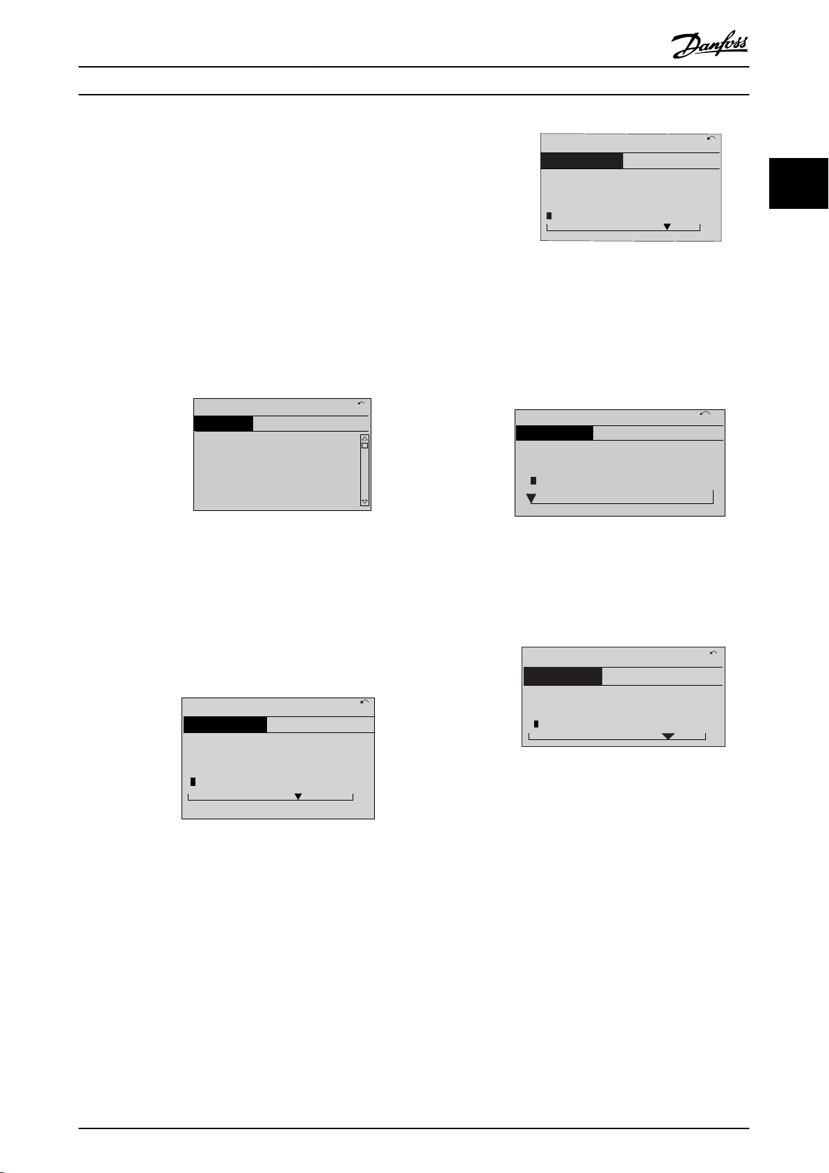
2.1.10 Changing Data
VLT® AutomationDrive Programming Guide
The procedure for changing data is the same in the Quick
and the Main menu mode. Press [OK] to change the
menu
selected parameter.
The procedure for changing data depends on whether the
selected parameter represents a numerical data value or a
text value.
2.1.11 Changing a Text Value
If the selected parameter is a text value, change the text
value
with the [▲] [▼] keys.
Place the cursor on the value to save and press [OK].
Illustration 2.16
2.1.12 Changing
If the chosen parameter represents a numeric data value,
the chosen data value by means of the [◀] [▶]
change
navigation keys as well as the [▲] [▼] navigation keys. Press
[◀] [▶] keys to move the cursor horizontally.
Illustration 2.18
2.1.13 Infinitely Variable Change of
Numeric
If the chosen parameter represents a numeric data value,
select
a digit with [◀] [▶].
Illustration 2.19
Change the selected digit infinitely variably with [▲] [▼].
The chosen digit is indicated by the cursor. Place the
cursor on the digit to save and press [OK].
Data Value
2 2
Illustration 2.17
Press [▲]
[▼] keys to change the data value. [▲] increases
the data value, and [▼] decreases the data value. Place the
cursor on the value to save and press [OK].
MG33MF02 - VLT® is a registered Danfoss trademark
Illustration 2.20
2.1.14 Value, Step-by-Step
Certain parameters can be changed step by step or
infinitely
1-22 Motor Voltage and 1-23 Motor Frequency.
The parameters are changed both as a group of numeric
data values and as numeric data values infinitely varying.
varying. This applies to 1-20 Motor Power [kW],
19
Page 21
130BA191.10
1
Auto
on
Reset
Hand
on
O
Menu
Status
Quick
Setup
Main
Menu
Back
2
3
4
OK
On
Alarm
Warn.
Setup
130BP077.10
22.8
rpm
Setup 1
How to Programme
VLT® AutomationDrive Programming Guide
2.1.15 Read-out and Programming of
Indexed
Parameters
22
Parameters are indexed when placed in a rolling stack.
15-30
Fault Log: Error Code to 15-32 Alarm Log: Time contain
a fault log which can be read out. Choose a parameter,
press [OK], and use [▲] [▼] to scroll through the value log.
Use 3-10 Preset Reference as another example:
Choose the parameter, press [OK], and use [▲] [▼] to scroll
through the indexed values. To change the parameter
value, select the indexed value and press [OK]. Change the
value by pressing [▲] [▼]. Press [OK] to accept the new
setting. Press [Cancel] to abort. Press [Back] to leave the
parameter.
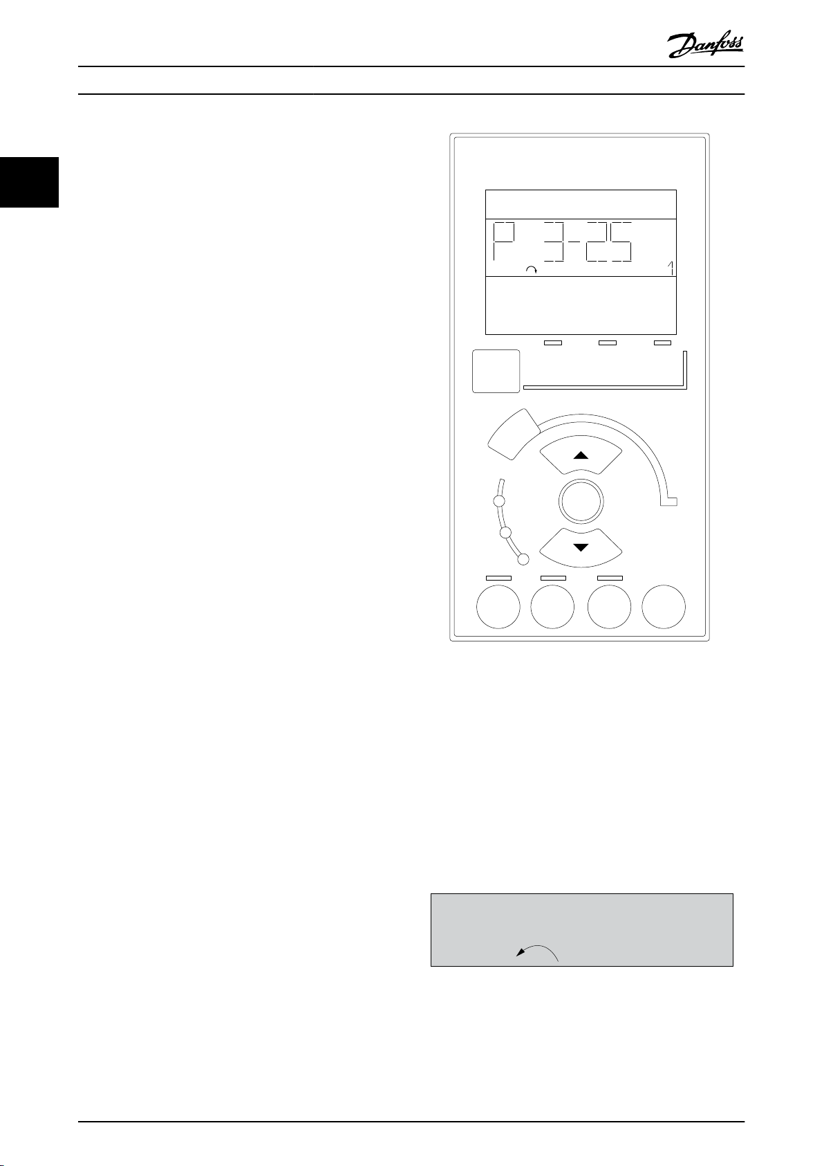
The following instructions are valid for the Numerical LCP
(LCP 101).
The control panel is divided into four functional groups:
1. Numerical display.
2. Menu keys and indicator lights - changing
parameters and switching between display
functions.
3. Navigation keys and indicator lights (LEDs).
4. Operation keys and indicator lights (LEDs).
Display line: Status messages displaying icons and numeric
value.
Indicator lights (LEDs)
Green LED/On: Indicates if control section is on.
•
Yellow LED/Wrn.: Indicates a warning.
•
Flashing red LED/Alarm: Indicates an alarm.
•
LCP keys
[Menu] Select one of the following modes:
Status
•
Quick Setup
•
Main Menu
•
Illustration 2.21
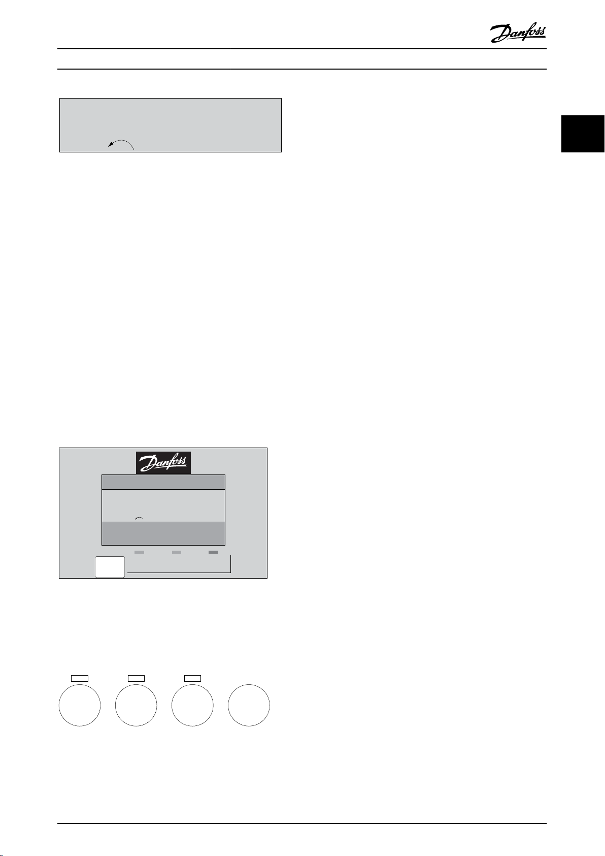
Mode
Status
Displays the status of the frequency converter or the
motor.
If an alarm occurs the NLCP automatically switches to
status mode.
A number of alarms can be displayed.
NOTE
Parameter copy is not possible with LCP 101 Numerical
Local Control Panel.
Illustration 2.22
20 MG33MF02 - VLT® is a registered Danfoss trademark
Page 22
Setup 1
130BP078.10
A 17
130BP079.10
Menu
Status Quick
Setup
Main
Menu
P 2-03
Setup 1
130BP046.10
Hand
on
O
Auto
on
Reset
How to Programme
Illustration 2.23
Main
Menu/Quick Setup is used for programming all
parameters or only the parameters in the Quick Menu (see
also description of the LCP 102 earlier in ).
The parameter values can be changed by pressing [▲] or
[▼] when the value is flashing.
Select Main Menu by pressing [Menu] a number of times.
Select the parameter group [xx-__] and press [OK]
Select the parameter [__-xx] and press [OK]
If the parameter is an array parameter select the array
number and press [OK]
Select the wanted data value and press [OK]
Parameters with functional choices display values such as
[1], [2], etc. For a description of the different choices, see
the individual description of the parameters in 3 Parameter
Descriptions
[Back] for stepping backwards
[▲] [▼] are used for manoeuvring between commands and
within parameters.
VLT® AutomationDrive Programming Guide
possible to enter the motor speed data by means of the
arrow
keys. The key can be selected as [1] Enable or [0]
Disable via 0-40 [Hand on] Key on LCP.
External stop signals activated by means of control signals
or a serial bus will override a 'start' command via the LCP.
The following control signals are still active when [Hand
On] is activated:
[Hand On] - [Off] - [Auto On]
•
Reset
•
Coasting stop inverse
•
Reversing
•
Set-up select lsb - Set-up select msb
•
Stop command from serial communication
•
Quick stop
•
DC brake
•
[Off] stops the connected motor. The key can be selected
as [1] Enable or [0] Disable via 0-41 [Off] Key on LCP.
If no external stop function is selected and the [Off] key is
inactive the motor can be stopped by disconnecting the
voltage.
[Auto On] enables the frequency converter to be
controlled via the control terminals and/or serial communication. When a start signal is applied on the control
terminals and/or the bus, the frequency converter will
start. The key can be selected as [1] Enable or [0] Disable
via 0-42 [Auto on] Key on LCP.
2 2
Illustration 2.24
2.1.16 Local Control Keys
Keys for local control are found at the bottom of the LCP.
Illustration 2.25
[Hand On] enables
the LCP. [Hand On] also starts the motor and it is now
control of the frequency converter via
NOTE
active HAND-OFF-AUTO signal via the digital inputs has
An
higher priority than the control keys [Hand On] [Auto On].
is used for resetting the frequency converter after
[Reset]
an alarm (trip). It can be selected as [1] Enable or [0]
Disable via 0-43 [Reset] Key on LCP.
2.1.17 Initialisation to Default Settings
Initialise the frequency converter to default settings in two
ways.
Recommended
1.
2. Press [OK]
3. Select “Initialisation”
4. Press [OK]
5. Cut off the mains supply and wait until the
initialisation (via 14-22 Operation Mode)
Select 14-22 Operation Mode
display turns off.
MG33MF02 - VLT® is a registered Danfoss trademark
21
Page 23

How to Programme
6. Reconnect the mains supply - the frequency
converter
22
14-22 Operation Mode initialises all except:
14-50 RFI Filter
8-30 Protocol
8-31 Address
8-32 FC Port Baud Rate
8-35 Minimum Response Delay
8-36 Max Response Delay
8-37 Max Inter-Char Delay
15-00 Operating Hours to 15-05 Over Volt's
15-20 Historic Log: Event to 15-22 Historic Log:
Time
15-30 Fault Log: Error Code to 15-32 Alarm Log:
Time
Manual initialisation
is now reset.
VLT® AutomationDrive Programming Guide
1. Disconnect from mains and wait until the display
turns off.
2. 2a Press [Status] - [Main Menu] - [OK] at
the same time while power up for LCP
102, Graphical Display
2b Press [Menu] while power up for LCP
101, Numerical Display
3. Release the keys after 5 s.
4. The frequency converter is now programmed
according to default settings.
This procedure initialises all except:
15-00 Operating Hours
15-03 Power Up's
15-04 Over Temp's
15-05 Over Volt's
NOTE
A
manual initialisation also resets serial communication, RFI
filter settings (14-50 RFI Filter) and fault log settings.
22 MG33MF02 - VLT® is a registered Danfoss trademark
Page 24

Parameter Descriptions
3 Parameter Descriptions
VLT® AutomationDrive Programming Guide
16-** Readout parameters
3.1 Parameter Selection
Parameters for FC 300 are grouped into various parameter
for easy selection of the correct parameters for
groups
optimized operation of the frequency converter.
0-** Operation and Display parameters
Basic Settings, set-up handling
•
Display and Local Control Panel parameters for
•
choosing readouts, setting up selections and
copying functions
1-** Load and Motor parameters includes all load and
motor related parameters
2-** Brake parameters
DC brake
•
Dynamic brake (Resistor brake)
•
Mechanical brake
•
Over Voltage Control
•
3-** References and ramping parameters includes DigiPot
function
17-**
Encoder Option parameters
18-** Readout 2 parameters
30-** Special Features
32-** MCO Basic Settings parameters
33-** MCO Adv. Settings parameters
34-** MCO Data Readouts
35-** Sensor Input Option parameters
Too see if a parameter can be used in a specific control
mode,
use the table in 4.1.2 Active/Inactive Parameters in
Different Drive Control Modes.
3 3
4-** Limits Warnings; setting of limits and warning
parameters
5-** Digital inputs and outputs includes relay controls
6-** Analog inputs and outputs
7-** Controls; Setting parameters for speed and process
controls
8-** Communication and option parameters for setting of
FC RS485 and FC USB port parameters.
9-** Profibus parameters
10-** DeviceNet and CAN Fieldbus parameters
12-** Ethernet parameters
13-** Smart Logic Control parameters
14-** Special function parameters
15-** Drive information parameters
MG33MF02 - VLT® is a registered Danfoss trademark
23
Page 25
Parameter Descriptions
VLT® AutomationDrive Programming Guide
3.2 Parameters: 0-** Operation and Display
Parameters related to the fundamental functions of the
frequency
ration of the LCP display.
33
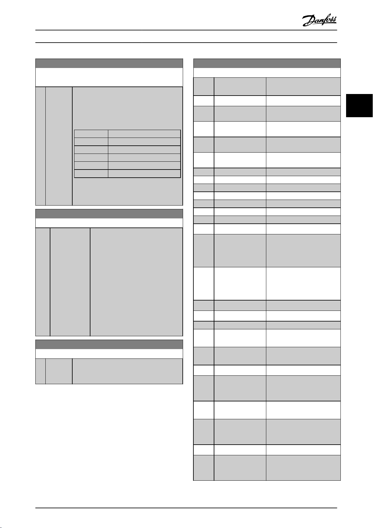
3.2.1 0-0* Basic Settings
converter, function of the LCP keys and configu-
0-01 Language
Option: Function:
[51] Bahasa Indonesia Part of Language package 2
[52] Hrvatski Part of Language package 3
0-02 Motor Speed Unit
Option: Function:
0-01 Language
Option: Function:
Defines the language to be used in the
The frequency converter can be
display.
delivered with 4 different language
packages. English and German are
included in all packages. English cannot
be erased or manipulated.
[0] * English Part of Language packages 1 - 4
The display showing depends on settings in
Motor Speed Unit and 0-03 Regional Settings. The
0-02
default setting of 0-02 Motor Speed Unit and
0-03 Regional Settings depends on which region of
the world the frequency converter is supplied to, but
can be re-programmed as required.
NOTE
Changing the Motor Speed Unit will reset certain
parameters to their initial value. It is
recommended to select the motor speed unit
[1] Deutsch Part of Language packages 1 - 4
[2] Francais Part of Language package 1
[3] Dansk Part of Language package 1
[4] Spanish Part of Language package 1
[5] Italiano Part of Language package 1
[6] Svenska Part of Language package 1
[0] RPM Selects display of motor speed variables and
[1] * Hz Selects display of motor speed variables and
first, before modifying other parameters.
parameters
terms of motor speed (RPM).
parameters
terms of output frequency to the motor (Hz).
(i.e. references, feedbacks and limits) in
(i.e. references, feedbacks and limits) in
[7] Nederlands Part of Language package 1
[10] Chinese Part of Language package 2
[20] Suomi Part of Language package 1
[22] English US Part of Language package 4
[27] Greek Part of Language package 4
[28] Bras.port Part of Language package 4
[36] Slovenian Part of Language package 3
[39] Korean Part of Language package 2
[40] Japanese Part of Language package 2
[41] Turkish Part of Language package 4
[42] Trad.Chinese Part of Language package 2
[43] Bulgarian Part of Language package 3
[44] Srpski Part of Language package 3
[45] Romanian Part of Language package 3
[46] Magyar Part of Language package 3
[47] Czech Part of Language package 3
[48] Polski Part of Language package 4
[49] Russian Part of Language package 3
NOTE
This
parameter cannot be adjusted while the motor is
running.
0-03 Regional Settings
Option: Function:
[0] * Interna-
tional
[1] US
Activates 1-20
the motor power in kW and sets the default
value of 1-23 Motor Frequency to 50Hz.
Activates 1-20
the motor power in HP and sets the default
value of 1-23 Motor Frequency to 60Hz.
Motor Power [kW] for setting
Motor Power [kW] for setting
NOTE
This
parameter cannot be adjusted while the motor is
running.
0-04 Operating State at Power-up (Hand)
Option: Function:
Selects the operating mode upon
reconnection of the frequency converter to
mains voltage after power down in Hand
(local) operation mode.
[0] Resume Restarts the frequency converter, maintaining
same and the same start/stop settings
the
[50] Thai Part of Language package 2
24 MG33MF02 - VLT® is a registered Danfoss trademark
Page 26
Parameter Descriptions
VLT® AutomationDrive Programming Guide
0-04 Operating State at Power-up (Hand)
Option: Function:
(applied by [Hand On/Off]) as before the
converter was powered down.
local reference, after mains voltage
the frequency converter.
[1] * Forced stop,
ref=old
[2] Forced stop,
ref=0
frequency
Restarts the frequency converter with a
saved
reappears and after pressing [Hand On].
Resets the local reference to 0 upon
restarting
3.2.2 0-1* Set-up Operations
Define and control the individual parameter setups.
The
frequency converter has four parameter setups that
can be programmed independently of each other. This
makes the frequency converter very flexible and able to
solve advanced control functionality problems, often
saving the cost of external control equipment. For example
these can be used to program the frequency converter to
operate according to one control scheme in one setup
(e.g. motor 1 for horizontal movement) and another
control scheme in another setup (e.g. motor 2 for vertical
movement). Alternatively they can be used by an OEM
machine builder to identically program all their factory
fitted frequency converters for different machine types
within a range to have the same parameters and then
during production/commissioning simply select a specific
setup depending on which machine the frequency
converter is installed on.
The active setup (i.e. the setup in which the frequency
converter is currently operating) can be selected in
0-10 Active Set-up and is displayed in the LCP. Using Multi
set-up it is possible to switch between setups with the
frequency converter running or stopped, via digital input
or serial communication commands. If it is necessary to
change setups whilst running, ensure 0-12 This Set-up
Linked to is programmed as required. Using 0-11 Edit Set-up
it is possible to edit parameters within any of the setups
whilst continuing the frequency converter operation in its
Active Setup which can be a different setup to that being
edited. Using 0-51 Set-up Copy it is possible to copy
parameter settings between the setups to enable quicker
commissioning if similar parameter settings are required in
different setups.
0-10 Active Set-up
Option: Function:
[1] * Set-up 1
[2] Set-up 2
[3] Set-up 3
[4] Set-up 4
[9] Multi Set-up Remote selection of set-ups using digital
Use 0-51
Set-up Copy to copy a set-up to one or all other
[1] Set-up 1
separate parameter set-ups within which all
parameters can be programmed.
inputs
This set-up uses the settings from 0-12 This
Set-up Linked to. Stop the frequency
converter before making changes to openand closed loop functions
to [4] Set-up 4 are the four
and the serial communication port.
set-ups. Stop the frequency converter before switching
between set-ups where parameters marked ‘not
changeable during operation’ have different values. To
avoid conflicting settings of the same parameter within
two different set-ups, link the set-ups together using
0-12 This Set-up Linked to. Parameters which are ‘not
changeable during operation’ are marked FALSE in the
parameter lists in 4 Parameter Lists.
0-11 Edit Set-up
Option: Function:
Select the set-up to be edited (i.e.
programmed)
active set-up or one of the inactive set-ups.
[0] Factory setup Cannot be edited but it is useful as a data
source
known state.
[1] * Set-up 1
[2] Set-up 2
[3] Set-up 3
[4] Set-up 4
[9] Active Set-up Can also be edited during operation. Edit
[1] Set-up 1
freely during operation, independently of
the active set-up.
chosen set-up from a range of sources:
the
LCP, FC RS-485, FC USB or up to five fieldbus
sites.
during operation; either the
to return the other set-ups to a
to [4] Set-up 4 can be edited
3 3
0-10 Active Set-up
Option: Function:
Select the set-up to control the frequency
converter
[0] Factory setup Cannot be changed. It contains the Danfoss
data
when returning the other set-ups to a
known state.
functions.
set, and can be used as a data source
MG33MF02 - VLT® is a registered Danfoss trademark
25
Page 27
130BA199.10
1
2
3
4
1
2
3
4
1
2
3
4
1
2
3
4
P 0-11
P 0-11
P 0-11
P 0-11
Set-up
Set-up
Set-up
Set-up
PLC Fieldbus
130BP075.10
0-12 This Set-up Linked to
0 RPM
0.00A
1(1)
Set-up Handling 0-1*
[1]
Setup 1
130BP076.10
0-12 This Set-up Linked to
0 RPM
0.00A
1(1)
Set-up Handling
0-1*
[2]
Setup 2
Parameter Descriptions
VLT® AutomationDrive Programming Guide
0-12 This Set-up Linked to
Option: Function:
Set-up 2 are synchronised (or ‘linked’). Synchro-
can be performed in two ways:
nisation
1. Change the edit set-up to Set-up 2 [2] in
33
0-11 Edit Set-up and set 0-12 This Set-up Linked
to to Set-up 1 [1]. This will start the linking
(synchronising) process.
Illustration 3.2
OR
While still in Set-up 1, copy Set-up 1 to Set-
2.
up 2. Then set 0-12 This Set-up Linked to to Set-
up 2 [2]. This will start the linking process.
Illustration 3.1
0-12 This Set-up Linked to
Option: Function:
26 MG33MF02 - VLT® is a registered Danfoss trademark
To enable conflict-free changes from one set-up
another during operation, link set-ups
to
containing parameters which are not
changeable during operation. The link will
ensure synchronising of the ‘not changeable
during operation’ parameter values when
moving from one set-up to another during
operation. ‘Not changeable during operation’
parameters can be identified by the label FALSE
in the parameter lists in the section Parameter
Lists.
0-12 This Set-up Linked to is used by Multi set-
up in 0-10 Active Set-up. Multi set-up is used to
move from one set-up to another during
operation (i.e. while the motor is running).
Example:
Use Multi set-up to shift from Set-up 1 to Setup 2 whilst the motor is running. Programme in
Set-up 1 first, then ensure that Set-up 1 and
[0] * Not linked
[1] Set-up 1
[2] Set-up 2
[3] Set-up 3
[4] Set-up 4
Illustration 3.3
After the link is complete, 0-13
Readout: Linked
Set-ups will read {1,2} to indicate that all ‘not
changeable during operation’ parameters are
now the same in Set-up 1 and Set-up 2. If there
are changes to a ‘not changeable during
operation’ parameter, e.g. 1-30 Stator Resistance
(Rs), in Set-up 2, they will also be changed
automatically in Set-up 1. A switch between
Set-up 1 and Set-up 2 during operation is now
possible.
Page 28
Parameter Descriptions
VLT® AutomationDrive Programming Guide
0-13 Readout: Linked Set-ups
Array [5]
Range: Function:
0 * [0 - 255 ] View a list of all the set-ups linked by means of
This Set-up Linked to. The parameter has one
0-12
index for each parameter set-up. The parameter
value displayed for each index represents which
set-ups are linked to that parameter set-up.
Index LCP value
0 {0}
1 {1,2}
2 {1,2}
3 {3}
4 {4}
Table 3.2 Example: Set-up 1 and Set-up 2 are
linked
0-14 Readout: Edit Set-ups / Channel
Range: Function:
0
N/A*
[-2147483648 2147483647
N/A]
View the setting of 0-11
each of the four different communication channels. When the number is
displayed in hex, as it is in the LCP, each
number represents one channel.
Numbers 1-4 represent a set-up number;
‘F’ means factory setting; and ‘A’ means
active set-up. The channels are, from
right to left: LCP, FC-bus, USB, HPFB1-5.
Example: The number AAAAAA21h
means that the FC bus selected Set-up 2
in 0-11 Edit Set-up, the LCP selected Setup 1 and all others used the active setup.
Edit Set-up for
0-15 Readout: actual setup
Range: Function:
0 * [0 - 255 ] Makes it possible to read out the active set-up,
when multi set-up is selected in 0-10 Active
also
Set-up.
3.2.3 0-2* LCP Display
Define the variables displayed in the Graphical Local
Control
Panel.
NOTE
Please
refer to 0-37 Display Text 1, 0-38 Display Text 2 and
0-39 Display Text 3 for information on how to write display
texts.
0-20 Display Line 1.1 Small
Option: Function:
Select a variable for display in
1, left position.
line
[0] * None No display value selected.
[953] Profibus Warning
Word
[1005] Readout Transmit
Counter
Error
[1006] Readout Receive Error
Counter
[1007] Readout Bus Off
Counter
[1013] Warning Parameter
[1230] Warning Parameter
[1472] VLT Alarm Word
[1473] VLT Warning Word
[1474] VLT Ext. Status Word
[1501] Running Hours
[1502] kWh Counter
[1600] Control Word Present control word
[1601] Reference [Unit] Total reference (sum of digital/
analog/preset/bus/freeze
catch up and slow-down) in
selected unit.
[1602] Reference % Total reference (sum of digital/
analog/preset/bus/freeze
catch up and slow-down) in
percent.
[1603] Status Word Present status word.
[1605] Main Actual Value [%] Actual value as a percentage.
[1609] Custom Readout
[1610] Power [kW] Actual power consumed by the
in kW.
motor
[1611] Power [hp] Actual power consumed by the
in HP.
motor
[1612] Motor Voltage Voltage supplied to the motor.
[1613] Frequency Motor frequency, i.e. the output
frequency
converter in Hz
[1614] Motor Current Phase current of the motor
measured
[1615] Frequency [%] Motor frequency, i.e. the output
frequency
converter in percent.
[1616] Torque [Nm] Actual motor torque in Nm
[1617] * Speed [RPM] Speed in RPM (revolutions per
minute)
speed in closed loop.
from the frequency
as effective value.
from the frequency
i.e. the motor shaft
ref./
ref./
3 3
MG33MF02 - VLT® is a registered Danfoss trademark
27
Page 29
Parameter Descriptions
VLT® AutomationDrive Programming Guide
0-20 Display Line 1.1 Small
Option: Function:
[1618] Motor Thermal Thermal load on the motor,
calculated
[1619] KTY sensor
33
[1620] Motor Angle
[1622] Torque [%] Present motor load as a
[1625] Torque [Nm] High
[1630] DC Link Voltage Intermediate circuit voltage in
[1632] Brake Energy /s Present brake power transferred
[1633] Brake Energy /2 min Brake power transferred to an
[1634] Heatsink Temp. Present heat sink temperature
[1635] Inverter Thermal Percentage load of the inverters.
[1636] Inv. Nom. Current Nominal current of the
[1637] Inv. Max. Current Maximum current of the
[1638] SL Controller State State of the event executed by
[1639] Control Card Temp. Temperature of the control card.
[1650] External Reference Sum of the external reference as
[1651] Pulse Reference Frequency in Hz connected to
[1652] Feedback [Unit] Reference value from
[1653] Digi Pot Reference
[1660] Digital Input Signal states form the 6 digital
temperature
percentage
torque.
the
to
Stated as an instantaneous
value.
external
mean power is calculated
continuously for the most
recent 120 s.
of
cut-out limit is 95 ±5 °C; cutting
back in occurs at 70 ±5 °C.
frequency
frequency
the
a
analog/pulse/bus.
the
33).
programmed
terminals
33). There are 16 bits in total,
but only six of them are used.
Input 18 corresponds to the
leftmost of the used bits. Signal
low = 0; Signal high = 1.
by the ETR function.
of the rated motor
frequency converter.
an external brake resistor.
brake resistor. The
the frequency converter. The
converter.
converter.
control.
percentage, i.e. the sum of
digital inputs (18, 19 or 32,
digital input(s).
(18, 19, 27, 29, 32 and
0-20 Display Line 1.1 Small
Option: Function:
[1661] Terminal 53 Switch
Setting
[1662] Analog Input 53 Actual value at input 53 either
[1663] Terminal 54 Switch
Setting
[1664] Analog Input 54 Actual value at input 54 either
[1665] Analog Output 42
[mA]
[1666] Digital Output [bin] Binary value of all digital
[1667] Freq. Input #29 [Hz] Actual value of the frequency
[1668] Freq. Input #33 [Hz] Actual value of the frequency
[1669] Pulse Output #27 [Hz] Actual value of impulses applied
[1670] Pulse Output #29 [Hz] Actual value of impulses applied
[1671] Relay Output [bin]
[1672] Counter A Application dependent (e.g. SLC
[1673] Counter B Application dependent (e.g. SLC
[1674] Prec. Stop Counter Display the actual counter value.
[1675] Analog In X30/11 Actual value at input X30/11
[1676] Analog In X30/12 Actual value at input X30/12
[1677] Analog Out X30/8
[mA]
[1678] Analog Out X45/1
[mA]
[1679] Analog Out X45/3
[mA]
[1680] Fieldbus CTW 1 Control word (CTW) received
Setting of input terminal 54.
= 0; Voltage = 1.
Current
a reference or protection
as
value.
Setting of input terminal 54.
= 0; Voltage = 1.
Current
reference or protection value.
as
Actual value at output 42 in
Use 6-50 Terminal 42 Output
mA.
to select the value to be shown.
outputs.
at terminal 29 as an
applied
impulse input.
at terminal 33 as an
applied
impulse input.
terminal 27 in digital output
to
mode.
terminal 29 in digital output
to
mode.
Control)
Control)
as reference or protection
either
value.
as reference or protection
either
value.
Actual value at output X30/8 in
Use 6-60 Terminal X30/8
mA.
Output to select the value to be
shown.
the Bus Master.
from
28 MG33MF02 - VLT® is a registered Danfoss trademark
Page 30
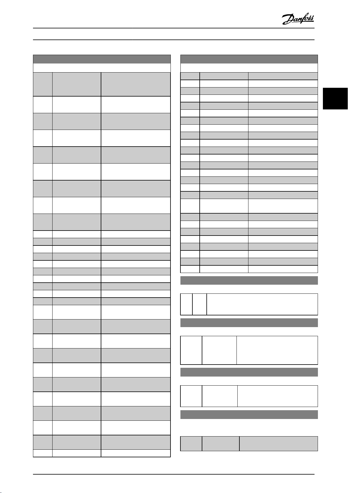
Parameter Descriptions
VLT® AutomationDrive Programming Guide
0-20 Display Line 1.1 Small
Option: Function:
[1682] Fieldbus REF 1 Main reference value sent with
word from the Bus
control
Master.
[1684] Comm. Option STW Extended fieldbus communi-
option status word.
cation
[1685] FC Port CTW 1 Control word (CTW) received
the Bus Master.
from
[1686] FC Port REF 1 Status word (STW) sent to the
Master.
Bus
[1690] Alarm Word One or more alarms in a Hex
code.
[1691] Alarm Word 2 One or more alarms in a Hex
code.
[1692] Warning Word One or more warnings in a Hex
code.
[1693] Warning Word 2 One or more warnings in a Hex
code.
[1694] Ext. Status Word One or more status conditions
a Hex code.
in
[3401] PCD 1 Write to MCO
[3402] PCD 2 Write to MCO
[3403] PCD 3 Write to MCO
[3404] PCD 4 Write to MCO
[3405] PCD 5 Write to MCO
[3406] PCD 6 Write to MCO
[3407] PCD 7 Write to MCO
[3408] PCD 8 Write to MCO
[3409] PCD 9 Write to MCO
[3410] PCD 10 Write to MCO
[3421] PCD 1 Read from
MCO
[3422] PCD 2 Read from
MCO
[3423] PCD 3 Read from
MCO
[3424] PCD 4 Read from
MCO
[3425] PCD 5 Read from
MCO
[3426] PCD 6 Read from
MCO
[3427] PCD 7 Read from
MCO
[3428] PCD 8 Read from
MCO
[3429] PCD 9 Read from
MCO
[3430] PCD 10 Read from
MCO
[3440] Digital Inputs
0-20 Display Line 1.1 Small
Option: Function:
[3441] Digital Outputs
[3450] Actual Position
[3451] Commanded Position
[3452] Actual Master Position
[3453] Slave Index Position
[3454] Master Index Position
[3455] Curve Position
[3456] Track Error
[3457] Synchronizing Error
[3458] Actual Velocity
[3459] Actual Master Velocity
[3460] Synchronizing Status
[3461] Axis Status
[3462] Program Status
[3470] MCO Alarm Word 1
[3471] MCO Alarm Word 2
[9913] Idle time
[9914] Paramdb requests in
queue
[9920] HS Temp. (PC1)
[9921] HS Temp. (PC2)
[9922] HS Temp. (PC3)
[9923] HS Temp. (PC4)
[9924] HS Temp. (PC5)
[9925] HS Temp. (PC6)
[9926] HS Temp. (PC7)
[9927] HS Temp. (PC8)
0-21 Display Line 1.2 Small
Option: Function:
[0] * None Select a variable for display in line 1, middle
The options are the same as listed for
position.
0-20 Display Line 1.1 Small.
0-22 Display Line 1.3 Small
Option: Function:
[30120] * Mains Current
[A]
Select a variable for display in line 1,
right
position. The options are the
same as listed for 0-20 Display Line 1.1
Small.
0-23 Display Line 2 Large
Option: Function:
[30100] * Output Current
[A]
Select a variable for display in line 2.
options are the same as listed for
The
0-20 Display Line 1.1 Small.
0-24 Display Line 3 Large
Select a variable for display in line 3.
Option: Function:
[30121] * Mains Frequency The options are the same as those
in 0-20 Display Line 1.1 Small.
listed
3 3
MG33MF02 - VLT® is a registered Danfoss trademark
29
Page 31

130BT105.11
0
Custom Readout (Value)
P 16-09
Custom Readout
Unit P 0-30
Max value
P 0-32
Min value
P 0-31
Motor Speed
Motor Speed
High limit
P 4-13 (RPM)
P 4-14 (Hz)
Quadratic Unit (Pressure)
Cubic Unit (Power)
Liniar
units only
Linear Unit (e.g. speed and flow)
Parameter Descriptions
VLT® AutomationDrive Programming Guide
0-25 My Personal Menu
Range: Function:
0
N/A*
33
3.2.4 0-3* LCP Custom Readout
It is possible to customize the display elements for various
purposes:
(Linear, squared or cubed depending on unit selected in
0-30 Custom Readout Unit) *Display Text. Text string stored
in a parameter.
Custom Readout
The calculated value to be displayed is based on settings
in 0-30 Custom Readout Unit, 0-31 Custom Readout Min
Value (linear only), 0-32 Custom Readout Max Value,
4-13 Motor Speed High Limit [RPM], 4-14 Motor Speed High
Limit [Hz] and actual speed.
Illustration 3.4
The relation will depend on the type of unit selected in
0-30
30 MG33MF02 - VLT® is a registered Danfoss trademark
[0 9999
N/A]
Define up to 50 parameters to appear in the Q1
Personal
Menu, accessible via the [Quick Menu]
key on the LCP. The parameters will be
displayed in the Q1 Personal Menu in the order
they are programmed into this array parameter.
Delete parameters by setting the value to ‘0000’.
For example, this can be used to provide quick,
simple access to just one or up to 50 parameters
which require changing on a regular basis (e.g.
for plant maintenance reasons) or by an OEM to
enable simple commissioning of their
equipment.
*Custom Readout. Value proportional to speed
Custom Readout Unit:
Unit Type Speed Relation
Dimensionless
Speed
Flow, volume
Flow, mass
Velocity
Length
Temperature
Pressure Quadratic
Power Cubic
Table 3.3
Linear
0-30 Unit for User-defined Readout
Option: Function:
It is possible to program a value to be shown in
display of the LCP. The value will have a
the
linear, squared or cubed relation to speed. This
relation will depend on the unit selected (see
table above). The actual calculated value can be
read in 16-09 Custom Readout, and/or shown in
the display be selecting Custom Readout [16-09]
in 0-20 Display Line 1.1 Small to 0-24 Display Line 3
Large.
[0] * None
[1] %
[5] PPM
[10] 1/min
[11] rpm
[12] Pulse/s
[20] l/s
[21] l/min
[22] l/h
[23] m³/s
[24] m³/min
[25] m³/h
[30] kg/s
[31] kg/min
[32] kg/h
[33] t/min
[34] t/h
[40] m/s
[41] m/min
[45] m
[60] °C
[70] mbar
[71] bar
[72] Pa
[73] kPa
[74] m WG
[80] kW
[120] GPM
[121] gal/s
[122] gal/min
[123] gal/h
Page 32

Parameter Descriptions
VLT® AutomationDrive Programming Guide
0-30 Unit for User-defined Readout
Option: Function:
[124] CFM
[125] ft³/s
[126] ft³/min
[127] ft³/h
[130] lb/s
[131] lb/min
[132] lb/h
[140] ft/s
[141] ft/min
[145] ft
[160] °F
[170] psi
[171] lb/in²
[172] in WG
[173] ft WG
[180] HP
0-31 Min Value of User-defined Readout
Range: Function:
0.00 CustomReadoutUnit*
[-999999.99 par. 0-32
CustomReadoutUnit]
This parameter sets the
min. value of the custom
defined readout (occurs at
zero speed). Only possible
to set different from 0 is
when selecting a linear unit
in 0-30 Unit for User-defined
Readout. For Quadratic and
Cubic units the minimum
value will be 0.
0-32 Custom Readout Max Value
Range: Function:
0-31 -
100.00 CustomReadoutUnit*
[ par.
999999.99
CustomReadoutUnit]
This parameter sets the max
value to be shown when
the speed of the motor has
reached the set value for
4-13 Motor Speed High Limit
[RPM] or 4-14 Motor Speed
High Limit [Hz] (depends on
setting in 0-02 Motor Speed
Unit).
0-38 Display Text 2
Range: Function:
0 * [0 - 0 ] Enter a text which can be viewed in the graphical
by selecting Display Text 2 [38] in
display
0-20 Display Line 1.1 Small, 0-21 Display Line 1.2
Small, 0-22 Display Line 1.3 Small, 0-23 Display Line 2
Large or 0-24 Display Line 3 Large.
0-39 Display Text 3
Range: Function:
0 * [0 - 0 ] Enter a text which can be viewed in the graphical
display
by selecting Display Text 3 [39] in
0-20 Display Line 1.1 Small, 0-21 Display Line 1.2
Small, 0-22 Display Line 1.3 Small, 0-23 Display Line 2
Large or 0-24 Display Line 3 Large.
3.2.5 0-4* LCP Keypad
Enable, disable and password protect individual keys on
LCP.
the
0-40 [Hand on] Key on LCP
Option: Function:
[0] * Disabled No effect when [Hand On] is pressed. Select [0]
Disabled
frequency converter in Hand on mode.
[1] * Enabled
[2] Password After pressing [Hand on] a password is required.
The LCP switches to Hand
when [Hand on] is pressed.
If
Personal Menu, define the password in 0-65 Quick
Menu Password. Otherwise define the password
in 0-60 Main Menu Password.
0-41 [Off] Key on LCP
Option: Function:
[0] * Disabled Avoids accidental stop of the frequency
converter.
[1] * Enabled
[2] Password
Avoids unauthorised stop. If 0-41
is included in the Quick Menu, then define the
password in 0-65 Quick Menu Password.
to avoid accidental start of the
on mode directly
0-40 [Hand on] Key on LCP is in included in My
[Off] Key on LCP
3 3
0-37 Display Text 1
Range: Function:
0 * [0 - 0 ] Enter a text which can be viewed in the graphical
by selecting Display Text 1 [37] in
display
0-20 Display Line 1.1 Small, 0-21 Display Line 1.2
Small, 0-22 Display Line 1.3 Small, 0-23 Display Line 2
Large or 0-24 Display Line 3 Large.
MG33MF02 - VLT® is a registered Danfoss trademark
0-42 [Auto on] Key on LCP
Option: Function:
[0] * Disabled Avoid accidental start of the frequency converter
Auto mode.
in
[1] * Enabled
[2] Password
Avoids unauthorised start in Auto mode. If
[Auto on] Key on LCP is included in the
0-42
Quick Menu, then define the password in
0-65 Quick Menu Password.
31
Page 33

Parameter Descriptions
VLT® AutomationDrive Programming Guide
0-43 [Reset] Key on LCP
Option: Function:
[0] * Disabled No effect when [Reset] is pressed. Avoids
accidental
[1] * Enabled
33
[2] Password
Avoids unauthorised resetting. If 0-43
on LCP is included in the Quick Menu, then
define the password in 0-65 Quick Menu
Password.
alarm reset.
[Reset] Key
3.2.6 0-5* Copy/Save
0-51 Set-up Copy
Option: Function:
[4] Copy to set-
4
up
[9] Copy to all Copies the parameters in the present set-up
Copies all parameters in the present
Programming Set-up (defined in
0-11 Programming Set-up) to Set-up 4.
to each of the set-ups 1 to 4.
over
3.2.7 0-6* Password
0-60 Main Menu Password
Range: Function:
Copy parameter settings between set-ups and to/from the
LCP.
0-50 LCP Copy
Option: Function:
[0] * No copy
[1] All to LCP Copies all parameters in all set-ups from
frequency converter memory to the
the
LCP memory.
[2] All from LCP Copies all parameters in all set-ups from
LCP memory to the frequency
the
converter memory.
[3] Size indep. from
LCP
[4] File from MCO
LCP
to
[5] File from LCP to
MCO
Copy only the parameters that are
independent
selection can be used to programme
several frequency converters with the
same function without disturbing motor
data.
of the motor size. The latter
100 * [0 - 999 ] Define the password for access to the Main
via the [Main Menu] key. If 0-61 Access
Menu
to Main Menu w/o Password is set to [0] Full
access, this parameter will be ignored.
0-61 Access to Main Menu w/o Password
Option: Function:
[0] * Full access
[1] LCP: Read only Prevent unauthorized editing of Main Menu
[2] LCP: No access Prevent unauthorized viewing and editing
[3] Bus: Read only Read-only functions for parameters on
[4] Bus: No access No access to parameters is allowed via
[5] All: Read only Read-only function for parameters on LCP,
[6] All: No access No access from LCP, Fieldbus or FC
Disables password defined in 0-60
Menu Password.
parameters.
Main Menu parameters.
of
and/or FC standard bus.
Fieldbus
and/or FC standard bus.
Fieldbus
or FC standard bus.
Fieldbus
standard
bus is allowed.
Main
NOTE
parameter cannot be adjusted while the motor is
This
running.
0-51 Set-up Copy
Option: Function:
[0] * No copy No function
[1] Copy to set-
1
up
[2] Copy to set-
2
up
[3] Copy to set-
3
up
Copies all parameters in the present
Programming Set-up (defined in
0-11 Programming Set-up) to Set-up 1.
Copies all parameters in the present
Programming Set-up (defined in
0-11 Programming Set-up) to Set-up 2.
Copies all parameters in the present
Programming Set-up (defined in
0-11 Programming Set-up) to Set-up 3.
access [0] is selected then 0-60 Main Menu Password,
If Full
0-65 Personal Menu Password and 0-66 Access to Personal
Menu w/o Password will be ignored.
NOTE
A
more complex Password protection is available for OEMs
upon request.
0-65 Quick Menu Password
Range: Function:
200 N/A* [-9999 -
N/A]
9999
Define the password for access to the
Quick Menu via the [Quick Menu] key.
If 0-66 Access to Quick Menu w/o
Password is set to [0] Full access, this
parameter will be ignored.
32 MG33MF02 - VLT® is a registered Danfoss trademark
Page 34
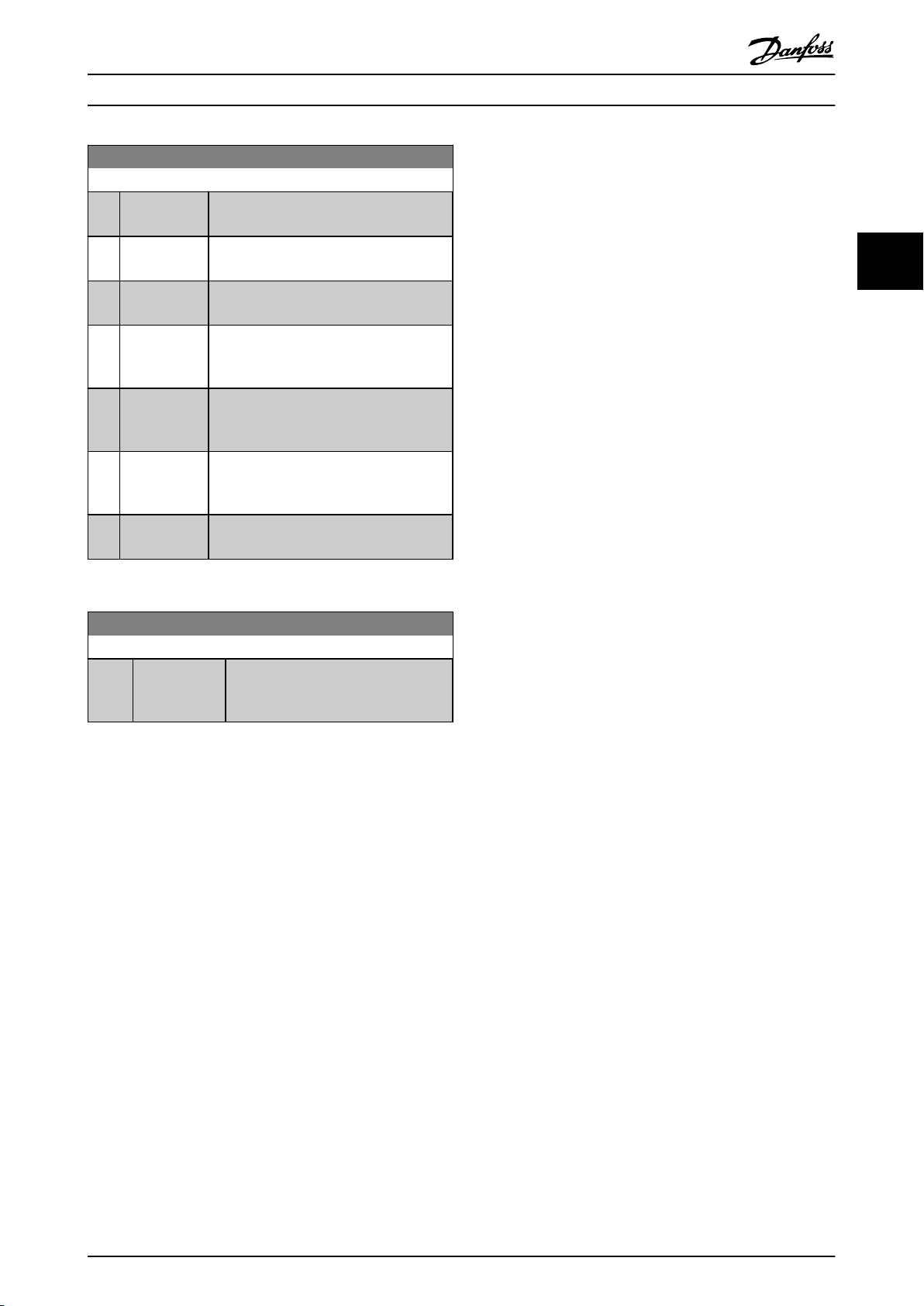
Parameter Descriptions
VLT® AutomationDrive Programming Guide
0-66 Access to Quick Menu w/o Password
Option: Function:
[0] * Full access
[1] LCP: Read only Prevents unauthorised editing of Quick
[2] LCP: No access Prevents unauthorised viewing and editing
[3] Bus: Read only Read only functions for Quick Menu
[4] Bus: No access No access to Quick Menu parameters is
[5] All: Read only read only function for Quick Menu
[6] All: No access No access from LCP, Fieldbus or FC
Disables the password defined in
Quick Menu Password.
0-65
parameters.
Menu
Quick Menu parameters.
of
parameters
standard bus.
allowed
bus.
parameters
bus.
standard
on Fieldbus and/ or FC
via Fieldbus and/ or FC standard
on LCP, Fieldbus or FC standard
bus is allowed.
3 3
Access to Main Menu w/o Password is set to [0] Full
If 0-61
access then this parameter will be ignored.
0-67 Bus Password Access
Range: Function:
0 N/A* [0 - 9999 N/A] Writing to this parameter enables users
to unlock the frequency converter from
bus/MCT 10 Set-up Software.
MG33MF02 - VLT® is a registered Danfoss trademark
33
Page 35
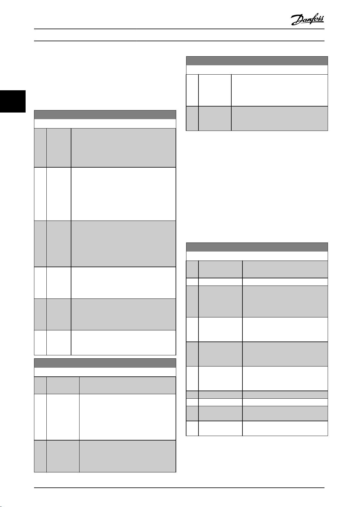
Parameter Descriptions
VLT® AutomationDrive Programming Guide
3.3 Parameters: 1-** Load and Motor
3.3.1 1-0* General Settings
Define whether the frequency converter operates in speed
or torque mode; and whether the internal PID
mode
33
control should be active or not.
1-00 Configuration Mode
Option: Function:
Select the application control principle to be
when a Remote Reference (i.e. via analog
used
input or fieldbus) is active. A Remote Reference
can only be active when 3-13 Reference Site is
set to [0] or [1].
[0] * Speed
open
loop
[1] Speed
closed
loop
[2] Torque Enables torque closed loop control with feed-
[3] Process Enables the use of process control in the
[4] Torque
open
loop
Enables speed control (without feedback signal
motor) with automatic slip compensation
from
for almost constant speed at varying loads.
Compensations are active but can be disabled
in the Load/Motor parameter group 1-0*. The
speed control parameters are set in parameter
group 7-0*.
Enables Speed closed loop control with feed-
Obtain full holding torque at 0 RPM.
back.
For increased speed accuracy, provide a
feedback signal and set the speed PID control.
The speed control parameters are set in
parameter group 7-0*.
Only possible with “Flux with motor
back.
feedback” option, 1-01 Motor Control Principle.
FC 302 only.
frequency
parameters are set in parameter groups 7-2*
and 7-3*.
Enables the use of torque open loop in VVC
mode
PID parameters are set in parameter group 7-1*.
converter. The process control
(1-01 Motor Control Principle). The torque
1-01 Motor Control Principle
Option: Function:
Select which motor control principle to
employ.
[0] * U/f special motor mode, for parallel connected
in special motor applications. When
motors
U/f is selected the characteristic of the
control principle can be edited in 1-55 U/f
Characteristic - U and 1-56 U/f Characteristic F.
[1] * VVC+ Voltage Vector Control principle suitable for
applications. The main benefit of
most
plus
VVC
operation is that it uses a robust
motor model.
+
1-01 Motor Control Principle
Option: Function:
[2] Flux
sensorless
[3] Flux w/
motor
feedb
Flux Vector control without encoder
feedback,
robustness against sudden load changes. FC
302 only.
very high accuracy speed and torque
control, suitable for the most demanding
applications. FC 302 only.
for simple installation and
The best shaft performance is normally achieved using
of the two Flux Vector control modes [2] Flux
either
sensorless and [3] Flux with encoder feedback.
NOTE
parameter cannot be adjusted while the motor is
This
running.
NOTE
overview of possible combinations of the settings in
An
1-00 Configuration Mode and 1-01 Motor Control Principle
can be found in 4.1.2 Active/Inactive Parameters in Different
Drive Control Modes.
1-02 Flux Motor Feedback Source
Option: Function:
Select the interface at which to receive
feedback
[0] Motor feedb. P1-02
[1] * 24V encoder A and B channel encoder, which can
be
terminals 32/33 only. Terminals 32/33
must be programmed to No operation.
[2] MCB 102 Encoder module option which can be
configured
FC 302 only.
[3] MCB 103 Optional resolver interface module
which
group 17-5*
[5] MCO Encoder 2 encoder interface 2 of the optional
programmable
305.
[6] Analog input 53
[7] Analog input 54
[8] Frequency input
29
[9] Frequency input
33
from the motor.
connected to the digital input
in parameter group 17-1*
can be configured in parameter
motion controller MCO
NOTE
This
parameter cannot be adjusted while the motor is
running.
34 MG33MF02 - VLT® is a registered Danfoss trademark
Page 36

Parameter Descriptions
VLT® AutomationDrive Programming Guide
1-03 Torque Characteristics
Option: Function:
Select the torque characteristic required.
and AEO are both energy saving
VT
operations.
[0] * Constant
torque
[1] Variable
torque
[2] Auto Energy
Optim.
Motor shaft output provides constant torque
variable speed control.
under
Motor shaft output provides variable torque
variable speed control. Set the
under
variable torque level in 14-40 VT Level.
Automatically optimises energy consumption
minimising magnetisation and frequency
by
via 14-41 AEO Minimum Magnetisation and
14-42 Minimum AEO Frequency.
NOTE
This
parameter cannot be adjusted while the motor is
running.
1-04 Overload Mode
Option: Function:
[0] * High torque Allows up to 160% over torque.
[1] Normal torque For oversized motor - allows up to 110%
torque.
over
NOTE
This
parameter cannot be adjusted while the motor is
running.
1-06 Clockwise Direction
This parameter defines the term “Clockwise” corresponding to
LCP direction arrow. Used for easy change of direction of
the
shaft rotation without swapping motor wires.
Option: Function:
converter is connected U ⇒
V⇒V, and W ⇒ W to motor.
[1] Inverse Motor shaft will turn in counter
clockwise
frequency converter is connected
U⇒U; V⇒V, and W⇒ W to motor.
direction when the
NOTE
This
parameter cannot be adjusted while the motor is
running.
1-07 Motor Angle Offset Adjust
This parameter will adjust the motor angle offset for an absolute
feedback device mounted on the motor.
position
Option: Function:
[0] Manual The frequency converter will use the motor angle
entered in 1-41 Motor Angle Offset.
offset
[1] Auto The frequency converter will automatically adjust
motor angle offset by running a determined
the
procedure.
NOTE
This
parameter is only valid when PM motors in Flux with
motor feedback are used and for FC 302 only.
U;
3 3
1-05 Local Mode Configuration
Option: Function:
Select which application configuration
mode (1-00 Configuration Mode), i.e.
application control principle, to use when a
Local (LCP) Reference is active. A Local
Reference can be active only when
3-13 Reference Site is set to [0] or [2]. By
default the local reference is active in Hand
Mode only.
[0] Speed open
loop
[1] Speed closed
loop
[2] * As mode par
1-00
1-06 Clockwise Direction
This parameter defines the term “Clockwise” corresponding to
LCP direction arrow. Used for easy change of direction of
the
shaft rotation without swapping motor wires.
Option: Function:
[0] * Normal Motor shaft will turn in clockwise
direction
when the frequency
3.3.2 1-1* Special Settings
NOTE
The
parameters within this parameter group cannot be
adjusted while the motor is running.
1-10 Motor Construction
Option: Function:
Select the motor design type.
[0] * Asynchron For asynchronous motors.
[1] PM, non salient
SPM
For salient or non-salient PM motors.
motors are divided into two groups,
PM
with either surface mounted (non salient)
or interior (salient) magnets.
MG33MF02 - VLT® is a registered Danfoss trademark
35
Page 37

Parameter Descriptions
VLT® AutomationDrive Programming Guide
1-11 Motor Model
Automatically sets the manufacturer’s values for the selected
If the default value [1] is used, settings must to be
motor.
determined manually, according to the choice in 1-10 Motor
Construction.
33
This parameter is FC 302 only.
Option: Function:
[1] Std. Asynchron
[2] Std. PM, non salient
[10] Danfoss OGD LA10
Default motor model when [0]*
Asynchron
Construction. Enter motor parameter
manually.
Selectable when [1]
SPM is selected in 1-10 Motor
Construction. Enter motor parameter
manually.
Selectable when [1]
SPM is selected in 1-10 Motor
Construction. Only available for T4, T5
in 1.5-3 kW. Settings are loaded
automatically for this specific motor.
See table for details.
is selected in 1-10 Motor
PM, non salient
PM, non salient
NOTE
This
parameter is FC 302 only.
1-16 High Speed Filter Time Const.
Range: Function:
is too short, the control gets
unstable.
1-17 Voltage filter time const.
Range: Function:
Size related* [0.001 - 1s]Reduces the influence of high
frequency
resonance in the calculation of
supply voltage. Without this filter, the
ripples in the currents can distort the
calculated voltage and affect the
stability of the system.
ripple and system
3.3.3 1-2* Motor Data
Parameter group 1-2* comprises input data from the
nameplate
on the connected motor.
NOTE
Changing
of other parameters.
the value of these parameters affects the setting
1-14 Damping Gain
Range: Function:
140%* [0 -
250
The damping gain will stabilize the PM machine
%]
in order to run the PM machine smooth and
stable. The value of Damping gain will control
the dynamic performance of the PM machine.
High damping gain will give high dynamic
performance and low damping gain will give low
dynamic performance. The dynamic performance
is related to the machine data and load type. If
the damping gain is too high or low the control
will become unstable.
1-15 Low Speed Filter Time Const.
Range: Function:
Size related* [0.01 - 20 s] This time constant is used below
rated speed. Obtain quick
10%
control through a short damping
time constant. However, if this value
is too short, the control gets
unstable.
1-16 High Speed Filter Time Const.
Range: Function:
Size related* [0.01 - 20 s] This time constant is used above
10% rated speed. Obtain quick
control through a short damping
time constant. However, if this value
NOTE
Motor Power [kW], 1-21 Motor Power [HP], 1-22 Motor
1-20
Voltage and 1-23 Motor Frequency will not have effect
when 1-10 Motor Construction = [1] PM, non salient SPM.
1-20 Motor Power [kW]
Range: Function:
4.00
kW*
[0.09 -
3000.00
kW]
Enter the nominal motor power in kW
according
The default value corresponds to the
nominal rated output of the unit.
This parameter cannot be adjusted while
the motor is running. This parameter is
visible in LCP if 0-03 Regional Settings is [0]
International.
to the motor nameplate data.
NOTE
Four sizes down, one size up from
nominal unit rating.
1-21 Motor Power [HP]
Range: Function:
4.00
hp*
[0.09 -
3000.00
Enter the nominal motor power in HP
hp]
according to the motor nameplate data.
The default value corresponds to the
nominal rated output of the unit. This
parameter is visible in LCP if
0-03 Regional Settings is [1] US
36 MG33MF02 - VLT® is a registered Danfoss trademark
Page 38

Parameter Descriptions
VLT® AutomationDrive Programming Guide
1-22 Motor Voltage
Range: Function:
500. V* [10. - 1000.V]Enter the nominal motor voltage
according
The default value corresponds to the
nominal rated output of the unit.
to the motor nameplate data.
1-23 Motor Frequency
Range: Function:
50.
Hz*
[20 1000
Hz]
Min - Max motor frequency: 20-1000 Hz.
Select
the motor frequency value from the
motor nameplate data. If a value different from
50 Hz or 60 Hz is selected, it is necessary to
adapt the load independent settings in
1-50 Motor Magnetisation at Zero Speed to
1-53 Model Shift Frequency. For 87 Hz operation
with 230/400 V motors, set the nameplate data
for 230 V/50 Hz. Adapt 4-13 Motor Speed High
Limit [RPM] and 3-03 Maximum Reference to the
87 Hz application.
1-24 Motor Current
Range: Function:
7.20 A* [0.10 - 10000.00A]Enter the nominal motor current
from the motor nameplate
value
data. The data are used for
calculating torque, motor protection
etc.
1-25 Motor Nominal Speed
Range: Function:
1420.
RPM*
[10 - 60000
RPM]
Enter the nominal motor speed value
the motor nameplate data. The
from
data are used for calculating motor
compensations. n
= ns - n
m,n
slip
1-26 Motor Cont. Rated Torque
Range: Function:
0 Nm* [0.1 -
10000.0
Enter the value from the motor nameplate
Nm]
data. The default value corresponds to the
nominal rated output. This parameter is
available when 1-10 Motor Construction is
set to [1] PM, non salient SPM, i.e. the
parameter is valid for PM and non-salient
SPM motors only.
1-29 Automatic Motor Adaptation (AMA)
Option: Function:
Activate the AMA function by pressing [Hand
after selecting [1] or [2]. See also the
on]
section Automatic Motor Adaptation in the
[0]*Off
[1] Enable
complete
AMA
[2] Enable
reduced
AMA
Design Guide. After a normal sequence, the
display will read: "Press [OK] to finish AMA".
After pressing the [OK] key the frequency
converter is ready for operation.
Performs AMA of the stator resistance RS,
rotor resistance Rr, the stator leakage reactance
X1, the rotor leakage reactance X2 and the
main reactance Xh. Do not select this option if
an LC filter is used between the frequency
converter and the motor.
FC 301: The Complete AMA does not include
Xh measurement for FC 301. Instead, the X
value is determined from the motor database.
RS is the best adjustment method (see 1-3*
Adv. Motor Data).
T4/T5 E and F Frames, T7 D, E and F Frames
will only run a Reduced AMA when the
complete AMA is selected. It is recommended
to obtain the Advanced Motor Data from the
motor manufacturer to enter into 1-31 Rotor
Resistance (Rr) through 1-36 Iron Loss Resistance
(Rfe) for best performance.
Performs a reduced AMA of the stator
resistance
Rs in the system only.
the
h
3 3
Note:
For
.
•
the best adaptation of the frequency
converter, run AMA on a cold motor.
AMA cannot be performed while the motor is
•
running.
AMA cannot be performed on permanent magnet
•
motors.
NOTE
This
parameter cannot be adjusted while the motor is
running.
1-29 Automatic Motor Adaptation (AMA)
Option: Function:
The AMA function optimises dynamic motor
performance
advanced motor parameters (1-30 Stator
Resistance (Rs) to 1-35 Main Reactance (Xh)) at
motor standstill.
by automatically optimising the
MG33MF02 - VLT® is a registered Danfoss trademark
NOTE
is important to set motor parameter group 1-2* Motor
It
Data correctly, since these form part of the AMA algorithm.
An AMA must be performed to achieve optimum dynamic
motor performance. It may take up to 10 min, depending
on the power rating of the motor.
NOTE
generating external torque during AMA.
Avoid
37
Page 39

130BA065.12
P 1-30
R
Fe
X
h
R'
r
R
s
U
1
I
1
P 1-33
P 1-34
P 1-31P 1-35P 1-36
X'
2δ
X
1δ
Parameter Descriptions
VLT® AutomationDrive Programming Guide
NOTE
one of the settings in parameter group 1-2* Motor Data
If
is changed, 1-30 Stator Resistance (Rs) to 1-39 Motor Poles,
the advanced motor parameters, will return to default
setting.
33
NOTE
will work problem-free on 1 motor size down,
AMA
typically work on 2 motor sizes down, rarely work on 3
sizes down and never work on 4 sizes down. Keep in mind
that the accuracy of the measured motor data will be
poorer when operating on motors smaller than nominal
frequency converter size.
3.3.4 1-3* Adv. Motor Data
Parameters for advanced motor data. The motor data in
Stator Resistance (Rs) to 1-39 Motor Poles must match
1-30
the relevant motor in order to run the motor optimally.
The default settings are figures based on common motor
parameter values from standard motors. If the motor
parameters are not set correctly, a malfunction of the
frequency converter system may occur. If the motor data is
not known, running an AMA (Automatic Motor Adaptation)
is recommended. See the Automatic Motor Adaptation
1-30 Stator Resistance (Rs)
Range: Function:
1.4000
Ohm*
[0.0140 -
140.0000
Ohm]
Set the stator resistance value.
Enter the value from a motor
data sheet or perform an AMA
on a cold motor.
1-31 Rotor Resistance (Rr)
Range: Function:
1.0000
Ohm*
[0.0100 -
100.0000
Ohm]
Fine-tuning Rr
performance. Set the rotor resistance value
using one of these methods:
1. Run an AMA on a cold motor.
2. Enter the Rr value manually.
3. Use the Rr default setting. The
will improve shaft
The frequency converter will
measure the value from the
motor. All compensations are
reset to 100%.
Obtain the value from the motor
supplier.
frequency converter establishes
the setting on the basis of the
motor nameplate data.
section in the Design Guide. The AMA sequence will adjust
all motor parameters except the moment of inertia of the
rotor and the iron loss resistance (1-36 Iron Loss Resistance
(Rfe)).
NOTE
Rotor Resistance (Rr) will not have effect when
1-31
1-10 Motor Construction = [1] PM, non salient SPM.
Parameter groups 1-3* and 1-4* cannot be adjusted while
the motor is running.
1-33 Stator Leakage Reactance (X1)
Range: Function:
Illustration 3.6 Motor equivalent diagram for an asynchronous
motor
NOTE
A
simple check of the X1 + Xh sum value is to divide the
4.0000
Ohm*
[0.0400 -
400.0000
Ohm]
Set the stator leakage reactance of the
using one of these methods:
motor
1. Run an AMA on a cold motor.
The frequency converter will
measure the value from the
motor.
2. Enter the X1 value manually.
Obtain the value from the
motor supplier.
3. Use the X1 default setting. The
frequency converter establishes
the setting on the basis of the
motor name plate data.
See Illustration 3.6.
line to line motor voltage by the sqrt(3) and divide this
value by the motor no load current. [VL-L/sqrt(3)]/INL = X1
+ Xh. These values are important to properly magnetize
the motor. For high pole motors it is highly recommended
to perform this check.
NOTE
1-33
Stator Leakage Reactance (X1) will not have effect
when 1-10 Motor Construction = [1] PM, non salient SPM.
38 MG33MF02 - VLT® is a registered Danfoss trademark
Page 40

Parameter Descriptions
VLT® AutomationDrive Programming Guide
1-34 Rotor Leakage Reactance (X2)
Range: Function:
4.0000
Ohm*
[0.0400 -
400.0000
Ohm]
Set the rotor leakage reactance of the
using one of these methods:
motor
1. Run an AMA on a cold motor.
The frequency converter will
measure the value from the
motor.
2. Enter the X2 value manually.
Obtain the value from the
motor supplier.
3. Use the X2 default setting. The
frequency converter establishes
the setting on the basis of the
motor name plate data.
See Illustration 3.6.
NOTE
Rotor Leakage Reactance (X2) will not have effect when
1-34
1-10 Motor Construction = [1] PM, non salient SPM.
1-35 Main Reactance (Xh)
Range: Function:
100.0000
Ohm*
[1.0000 -
10000.0000
Ohm]
Set the main reactance of the motor
one of these methods:
using
1. Run an AMA on a cold
motor. The frequency
converter will measure the
value from the motor.
2. Enter the Xh value manually.
Obtain the value from the
motor supplier.
3. Use the Xh default setting.
The frequency converter
establishes the setting on
the basis of the motor name
plate data.
1-37 d-axis Inductance (Ld)
Range: Function:
0 mH* [0 - 0
mH]
Enter the value of the d-axis inductance.
the value from the permanent magnet
Obtain
motor data sheet.
This parameter is only active when 1-10 Motor
Construction has the value [1] PM, non-salient
SPM (Permanent Magnet Motor).
For a selection with one decimal, use this
parameter. For a selection with three decimals,
use 30-80 d-axis Inductance (Ld).
FC 302 only.
1-38 q-axis Inductance (Lq)
Range: Function:
Size related* [0.000 - 1000
mH]
Set the value of the q-axis
inductance.
sheet.
3 3
See a motor data
1-36 Iron Loss Resistance (Rfe)
Range: Function:
10000.000
Ohm*
[0 -
10000.000
Ohm]
Enter the equivalent iron loss
resistance
compensate for iron loss in the
motor.
The RFe value cannot be found by
performing an AMA.
The RFe value is especially
important in torque control
applications. If RFe is unknown,
leave 1-36 Iron Loss Resistance (Rfe)
on default setting.
(RFe) value to
MG33MF02 - VLT® is a registered Danfoss trademark
39
Page 41

Magn. current
130BA045.11
Hz
Par.1-50
Par.1-51
100%
Par.1-52 RPM
Parameter Descriptions
VLT® AutomationDrive Programming Guide
1-39 Motor Poles
Range: Function:
4. N/A* [2 - 100 N/A] Enter the number of motor poles.
Poles ~nn@
33
2 2700-2880 3250-3460
4 1350-1450 1625-1730
6 700-960 840-1153
Table 3.4
The
table shows the number of poles for normal speed
50Hz ~nn@60Hz
ranges of various motor types. Define motors designed for
other frequencies separately. The motor pole value is
always an even number, because it refers to the total
number of poles, not pairs of poles. The frequency
converter creates the initial setting of 1-39 Motor Poles
based on 1-23 Motor Frequency and 1-25 Motor Nominal
Speed.
1-40 Back EMF at 1000 RPM
Range: Function:
500. V* [10. 9000
Set the nominal back EMF for the motor
V]
when running at 1000 RPM. This parameter
is only active when 1-10 Motor Construction
is set to [1] PM motor (Permanent Magnet
Motor).
FC 302 only.
1-47 Low Speed Torque Calibration
This parameter is used to optimize the torque estimate at low
When running open loop flux at low speed the estimated
speed.
torque is based on shaft power, P
that it is important to have the correct Rs. The Rs in this formula
must be equal to the loss in both motor, cable and frequency
converter. Sometimes it is not possible to adjust 1-30 Stator
Resistance (Rs) on each frequency converter to compensate for
cable length, frequency converter losses and temperature
deviation on motor. Therefore the frequency converter must be
able to calculate Rs when starting.
The parameter is only active when running PM motor in Flux
Open Loop.
= Pm - Rs * I2. This means
shaft
Option: Function:
[0] Off
[1] 1st start after pwr-upCalibrates at the first start-
up
after power up and
keeps this value until reset
by a power cycle.
[2] Every start Calibrates at every start-up,
compensating
change in motor
temperature since last startup.
for a possible
3.3.5 1-5* Load Indep. Setting
NOTE
When using PM motors, it is
recommended to use brake resistors.
1-41 Motor Angle Offset
Range: Function:
0
[-32768 -
N/A*
32767 N/A]
1-46 Position Detection Gain
Range: Function:
100 %* [20 - 200 %] Adjusts the amplitude of the test pulse
Enter the correct offset angle between the
PM motor and the index position (single-turn)
of the attached encoder or resolver. The
value range of 0 - 32768 corresponds to 0 - 2
* pi (radians). To obtain the offset angle
value: After frequency converter start-up
apply DC-hold and enter the value of
16-20 Motor Angle into this parameter.
This parameter is only active when
1-10 Motor Construction is set to [1] PM, nonsalient SPM (Permanent Magnet Motor).
position detection at start. Adjust
during
this parameter to improve the position
measurement.
1-50 Motor Magnetisation at Zero Speed
Range: Function:
100%* [0 -
300
%]
Use this parameter along with 1-51
Normal Magnetising [RPM] to obtain a different
thermal load on the motor when running at low
speed.
Enter a value which is a percentage of the rated
magnetizing current. If the setting is too low, the
torque on the motor shaft may be reduced.
Illustration 3.7
Min Speed
NOTE
1-50
Motor Magnetisation at Zero Speed will not have effect
when 1-10 Motor Construction = [1] PM, non salient SPM.
40 MG33MF02 - VLT® is a registered Danfoss trademark
Page 42
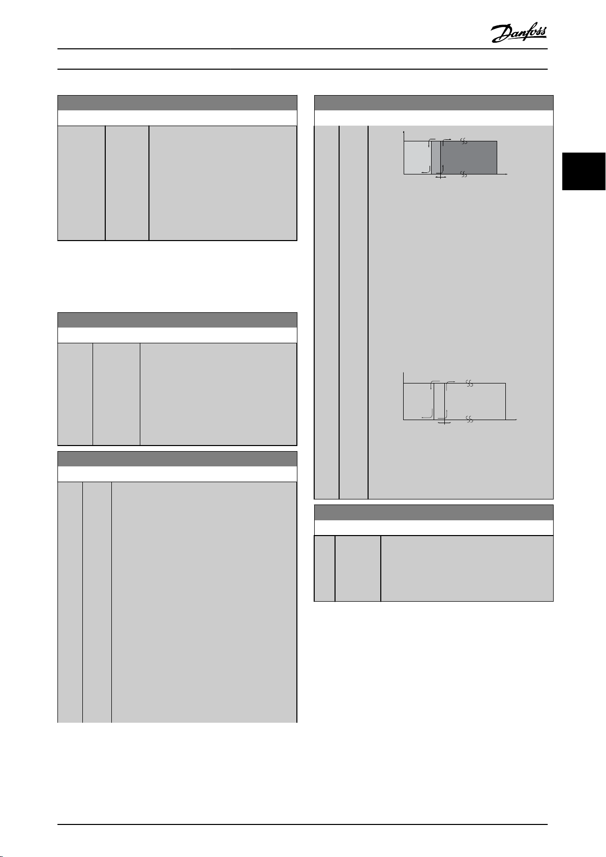
P 1-53
130BA146.11
f
out
f
N,M
x 0.125 f
N,M
x 0.1
Flux model 2Flux model 1
P 1-53
130BA147.10
x 0.1
Variable
current
model
Flux model 2
f
out
f
N,M
f
N,M
x 0.125
Parameter Descriptions
VLT® AutomationDrive Programming Guide
1-51 Min Speed Normal Magnetising [RPM]
Range: Function:
Size
related*
[10 - 300
RPM]
Set the required speed for normal
magnetising
current. If the speed is set
lower than the motor slip speed,
1-50 Motor Magnetisation at Zero Speed
and 1-51 Min Speed Normal Magnetising
[RPM] are of no significance.
Use this parameter along with
1-50 Motor Magnetisation at Zero Speed.
See Table 3.4.
NOTE
1-51
Min Speed Normal Magnetising [RPM] will not have
effect when 1-10 Motor Construction = [1] PM, non salient
SPM.
1-52 Min Speed Normal Magnetising [Hz]
Range: Function:
12.5 Hz* [0 - 250.0
Hz]
1-53 Model Shift Frequency
Range: Function:
0
[4.0
0
Hz*
Hz]
Set the required frequency for normal
magnetising
current. If the frequency is set
lower than the motor slip frequency,
1-50 Motor Magnetisation at Zero Speed is
inactive.
Use this parameter along with 1-50 Motor
Magnetisation at Zero Speed. See drawing
for 1-50 Motor Magnetisation at Zero Speed.
Flux Model shift
Enter the frequency value for shift between two
models for determining motor speed. Choose the
value based on settings in 1-00 Configuration Mode
and 1-01 Motor Control Principle. There are two
options: shift between Flux model 1 and Flux
model 2; or shift between Variable Current mode
and Flux model 2.FC 302 only.
This parameter cannot be adjusted while the
motor is running.
Flux Model 1 – Flux model 2
This model is used when 1-00 Configuration Mode
is set to Speed closed loop [1] or Torque [2] and
1-01 Motor Control Principle is set to Flux w/motor
feedback [3]. With this parameter it is possible to
make an adjustment of the shifting point where
FC 302 changes between Flux model 1 and Flux
model 2, which is useful in some sensitive speed
and torque control applications.
1-53 Model Shift Frequency
Range: Function:
Illustration 3.8 1-00
Speed closed loop or [2] Torque and 1-01 Motor
Control Principle = [3] Flux w/motor feedback
Variable Current - Flux model - Sensorless
This model is used when 1-00 Configuration Mode
is set to Speed open loop [0] and 1-01 Motor
Control Principle is set to Flux sensorless [2].
In speed open loop in flux mode, the speed is
determined from the current measurement.
Below f
x 0.1, the frequency converter runs on
norm
a Variable Current model. Above f
frequency converter runs on a Flux model.
Illustration 3.9 1-00
Speed open loop, 1-01 Motor Control Principle =
[2] Flux sensorless
Configuration Mode = [1]
x 0.125 the
norm
Configuration Mode = [0]
1-54 Voltage reduction in fieldweakening
Range: Function:
0 V* [0 - 100V]The value of this parameter will reduce the
maximal voltage available for the flux of the
motor in fieldweakning, giving more voltage
available for torque. Be aware that too high
value may give stall problems at high speed.
3 3
MG33MF02 - VLT® is a registered Danfoss trademark
41
Page 43

Motor Voltage
Par 1-55 [x]
Output Frequency
Par 1-56 [x]
1-55[5]
1-55[4]
1-55[3]
1-55[2]
1-55[1]
1-55[0]
1-56
[0]
1-56
[1]
1-56
[2]
1-56
[3]
1-56
[4]
1-56
[5]
130BA166.10
130BA046.11
60%
0%
100%
U
m
Changeover
f
out
Par.1-60 Par.1-61
Parameter Descriptions
VLT® AutomationDrive Programming Guide
1-55 U/f Characteristic - U
Range: Function:
0 V* [0.0 -
V]
1000.0
33
Enter the voltage at each frequency point to
manually form a U/f characteristic matching
the motor.
The frequency points are defined in 1-56 U/f
Characteristic - F.
This parameter is an array parameter [0-5]
and is only accessible when 1-01 Motor
Control Principle is set to [0] U/f.
1-59 Flystart Test Pulses Frequency
Range: Function:
-
Size
related*
Sets the frequency of the flystart test pulses
[ 0
0 %]
that are used to detect the motor direction.
100% means means 2 x fslip. Increase this
value to reduce the generated torque. For
PM motors this value is the percentage
nm,n of the free running PM motor. Above
this value flystart is always performed. Below
this value, the start mode is selected in
1-70 PM Start Mode
1-56 U/f Characteristic - F
This parameter is only available in VVC
plus
.
Range: Function:
0 Hz* [0 - 1000.0
Hz]
Enter the frequency points to manually
form
a U/f-characteristic matching the
motor.
The voltage at each point is defined in
1-55 U/f Characteristic - U.
This parameter is an array parameter [0-5]
and is only accessible when 1-01 Motor
Control Principle is set to [0] U/f.
3.3.6 1-6* Load Depend. Setting
1-60 Low Speed Load Compensation
Range: Function:
100 %* [0 - 300%]Enter the % value to compensate voltage in
to load when the motor is running
relation
at low speed and obtain the optimum U/f
characteristic. The motor size determines
the frequency range within which this
parameter is active.
Illustration 3.10
1-58 Flystart Test Pulses Current
Range: Function:
-
Size
related*
42 MG33MF02 - VLT® is a registered Danfoss trademark
Sets the current level for the flystart test
[ 0
0 %]
pulses that are used to detect the motor
direction. 100% means I
be big enough to avoid noise influence but
low enough to avoid affecting the accuracy
(current must be able to drop to zero before
the next pulse). Reduce the value to reduce
the generated torque.
Default is 30% for asynchronous motors, but
may vary for PM motors. For PM motors
adjusting the value will tune for back EMF and
d-axis inductance of the motor.
This parameter is only available in VVC
. Adjust the value to
m,n
plus
Motor size Change over
0.25 kW - 7.5 kW < 10 Hz
Table 3.5
Illustration 3.11
1-61 High Speed Load Compensation
Range: Function:
100 %* [0 - 300%]Enter the % value to compensate voltage in
to load when the motor is running
relation
at high speed and obtain the optimum U/f
characteristic. The motor size determines
.
the frequency range within which this
parameter is active.
Page 44

Parameter Descriptions
VLT® AutomationDrive Programming Guide
Motor size Change-over
0.25 kW - 7.5 kW > 10 Hz
Table 3.6
1-62 Slip Compensation
Range: Function:
100.%* [-500 500 %]
Enter the % value for slip compensation, to
compensate for tolerances in the value of
n
. Slip compensation is calculated automat-
M,N
ically, i.e. on the basis of the rated motor
speed n
This function is not active when 1-00 Configu-
ration Mode is set to [1] Speed closed loop or
[2] Torque Torque control with speed feedback
or when 1-01 Motor Control Principle is set to
[0] U/f special motor mode.
M,N
.
1-63 Slip Compensation Time Constant
Range: Function:
Size related* [0.05 - 5.00s]Enter the slip compensation reaction
A high value results in slow
speed.
reaction, and a low value results in
quick reaction. If low-frequency
resonance problems arise, use a
longer time setting.
NOTE
1-63 Slip Compensation Time Constant will not have effect
when 1-10 Motor Construction = [1] PM, non salient SPM.
NOTE
Resonance Dampening Time Constant will not have
1-65
effect when 1-10 Motor Construction = [1] PM, non salient
SPM.
1-66 Min. Current at Low Speed
Range: Function:
100%* [1. -
200.
Enter the minimum motor current at low speed,
%]
see 1-53 Model Shift Frequency. Increasing this
current improves motor torque at low speed.
1-66 Min. Current at Low Speed is enabled when
1-00 Configuration Mode [0] Speed open loop only.
The frequency converter runs with constant
current through motor for speeds below 10æHz.
For speeds above 10æHz, the motor flux model
in the frequency converter controls the motor.
4-16 Torque Limit Motor Mode andæ/æor
4-17 Torque Limit Generator Mode automatically
adjust 1-66 Min. Current at Low Speed. The
parameter with the highest value adjusts
1-66 Min. Current at Low Speed. The current
setting in 1-66 Min. Current at Low Speed is
composed of the torque generating current and
the magnetizing current.
Example: Set 4-16 Torque Limit Motor Mode to
100% and set 4-17 Torque Limit Generator Mode
to 60%. 1-66 Min. Current at Low Speed automatically adjusts to about 127%, depending on the
motor size.
FC 302 only.
3 3
1-64 Resonance Dampening
Range: Function:
100 %* [0 - 500
%]
Enter the resonance dampening value. Set
Resonance Dampening and
1-64
1-65 Resonance Dampening Time Constant to
help eliminate high-frequency resonance
problems. To reduce resonance oscillation,
increase the value of 1-64 Resonance
Dampening.
NOTE
1-64
Resonance Dampening will not have effect when
1-10 Motor Construction = [1] PM, non salient SPM.
1-65 Resonance Dampening Time Constant
Range: Function:
5 ms* [5 - 50 ms]
Resonance Dampening and
Set 1-64
1-65 Resonance Dampening Time Constant to
help eliminate high-frequency resonance
problems. Enter the time constant that
provides the best dampening.
1-67 Load Type
Option: Function:
[0] * Passive load For conveyers, fan and pump applications.
[1] Active load For hoisting applications, used in slip
compensation
[1] is selected, set 1-66 Min. Current at Low
Speed to a level which corresponds to
maximum torque.
at low speed. When Active Load
FC 302 only.
1-68 Minimum Inertia
Range: Function:
0.0048
kgm²*
[0.0001 par.
1-69
kgm²]
Needed for average inertia calculation.
Enter the minimum moment of inertia of
the mechanical system. 1-68 Minimum
Inertia and 1-69 Maximum Inertia are
used for pre-adjustment of the Proportional Gain in the speed control, see
30-83 Speed PID Proportional Gain.
FC 302 only.
NOTE
parameter cannot be adjusted while motor is running.
This
MG33MF02 - VLT® is a registered Danfoss trademark
43
Page 45
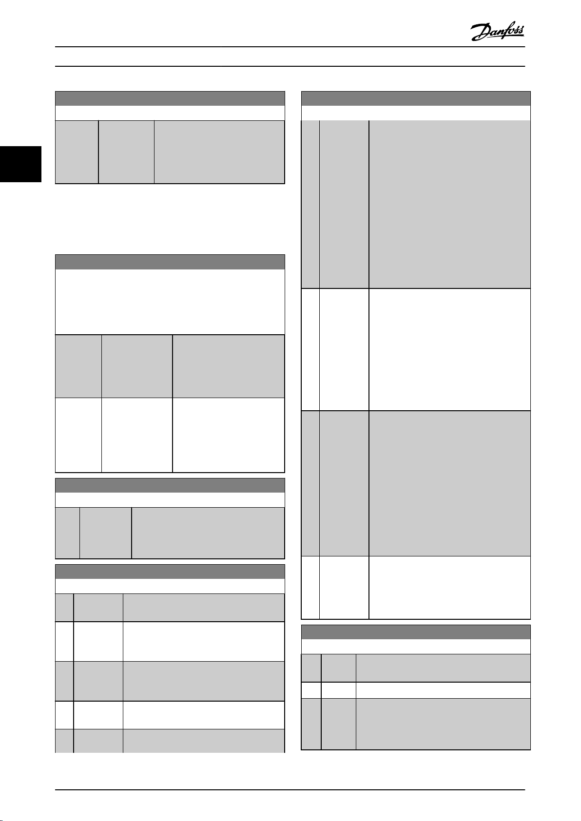
Parameter Descriptions
VLT® AutomationDrive Programming Guide
1-69 Maximum Inertia
Range: Function:
0.0048
kgm²*
[par. 1-68 -
kgm²]
0.4800
33
Active in Flux Open Loop only. Used
to compute the acceleration torque
at low speed. Used in the torque
limit controller.
FC 302 only.
NOTE
This
parameter cannot be adjusted while motor is running.
3.3.7 1-7* Start Adjustments
1-70 PM Start Mode
Select the PM motor start-up mode. This is done to initialize the
plus
control core for previously free running PM motor. Both
VVC
selections will estimate the speed and angle. Active for PM
motors in VVC
Option: Function:
[0] Rotor Detection Estimates the electrical angle
[1] Parking The Parking function applies
1-71 Start Delay
Range: Function:
0.0 s* [0.0 - 10.0 s] This parameter refers to the start function
1-72 Start Function
Option: Function:
[0] DC Hold/
delay
[1] DC Brake/
delay
[2]*Coast/delay
time
[3] Start speed
cw
time
time
plus
only.
of
the rotor and uses this as a
starting point. Standard
selection for AutomationDrive
applications.
current across the stator
DC
winding and rotates the rotor
to electrical zero position
(typically selected for HVAC
applications).
in 1-72 Start Function.
selected
Enter the time delay required before
commencing acceleration.
Select the start function during start delay.
This
parameter is linked to 1-71 Start Delay.
Energizes motor with a DC holding current
(2-00 DC Hold Current) during the start delay
time.
Energizes motor with a DC braking current
(2-01 DC Brake Current) during the start delay
time.
Motor coasted during the start delay time
off).
(inverter
Only possible with VVC
plus
.
1-72 Start Function
Option: Function:
Start
Start Speed
/Flux clockwise
[4] Horizontal
operation
[5] VVC+/Flux
clockwise
[6] Hoist Mech.
Rel
Brake
Connect the function described in 1-74
Speed [RPM] and 1-76 Start Current in the start
delay time.
Regardless of the value applied by the
reference signal, the output speed applies the
setting of the start speed in 1-74 Start Speed
[RPM] or 1-75 Start Speed [Hz] and the output
current corresponds to the setting of the start
current in 1-76 Start Current. This function is
typically used in hoisting applications without
counterweight and especially in applications
with a Cone-motor, where the start is
clockwise, followed by rotation in the
reference direction.
Only possible with VVC
obtaining the function described in
For
1-74 Start Speed [RPM] and 1-76 Start Current
during the start delay time. The motor rotates
in the reference direction. If the reference
signal equals zero (0), 1-74 Start Speed [RPM]
is ignored and the output speed equals zero
(0). The output current corresponds to the
setting of the start current in 1-76 Start
Current.
for the function described in 1-74
[RPM] only. The start current is calculated
automatically. This function uses the start
speed in the start delay time only. Regardless
of the value set by the reference signal, the
output speed equals the setting of the start
speed in 1-74 Start Speed [RPM].Start speed/
current clockwise [3] and VVC
[5] are typically used in hoisting applications.
Start speed/current in reference direction [4] is
particularly used in applications with counterweight and horizontal movement.
For utilizing mechanical brake control
functions, 2-24 Stop Delay to 2-28 Gain Boost
Factor. This parameter is only active when
1-01 Motor Control Principle is set to [3] Flux
w/ motor feedback (FC 302 only).
plus
.
plus
1-73 Flying Start
Option: Function:
This function makes it possible to catch a motor
which
is spinning freely due to a mains drop-out.
[0] * Disabled No function
[1] Enabled Enables the frequency converter to “catch” and
a spinning motor.
control
When 1-73 Flying Start is enabled, 1-71 Start Delay
and 1-72 Start Function have no function.
44 MG33MF02 - VLT® is a registered Danfoss trademark
Page 46
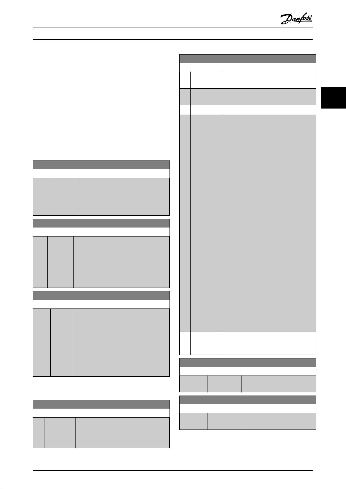
Parameter Descriptions
VLT® AutomationDrive Programming Guide
NOTE
parameter cannot be adjusted while motor is running.
This
NOTE
function is not recommended for hoisting
This
applications.
For power levels above 55 kW, flux mode must be used to
achieve the best performance.
NOTE
obtain the best flying start performance the advanced
To
motor data, 1-30 Stator Resistance (Rs) through 1-35 Main
Reactance (Xh), must be correct.
1-74 Start Speed [RPM]
Range: Function:
0 RPM* [0 - 600
RPM]
1-75 Start Speed [Hz]
Range: Function:
0 Hz* [0.0 -
Hz]
500.0
1-76 Start Current
Range: Function:
0.00A* [0.00 1-24
par.
A]
3.3.8 1-8* Stop Adjustments
Set a motor start speed. After the start
signal,
the output speed leaps to set value.
Set the start function in 1-72 Start Function
to [3], [4] or [5], and set a start delay time
in 1-71 Start Delay.
This parameter can be used for hoist
applications (cone rotor). Set a motor start
speed. After the start signal, the output
speed leaps to set value. Set the start
function in 1-72 Start Function to [3], [4] or
[5], and set a start delay time in 1-71 Start
Delay.
Some motors, e.g. cone rotor motors, need
extra current/starting speed to disengage the
rotor. To obtain this boost, set the required
current in 1-76 Start Current. Set 1-74 Start
Speed [RPM]. Set 1-72 Start Function to [3] or
[4], and set a start delay time in 1-71 Start
Delay.
This parameter can be used for hoist
applications (cone rotor).
1-80 Function at Stop
Option: Function:
[0]*Coast Leaves motor in free mode. The motor is
disconnected
[1] DC hold Energizes motor with a DC holding current
2-00 DC Hold Current).
(see
[2] Motor check Checks if a motor has been connected.
[3] Pre-
magnetizing
[4] DC Voltage
U0
Builds up a magnetic field while the motor
stopped. This allows the motor to produce
is
torque quickly at subsequent start
commands (asynchronous motors only). This
Pre-magnetizing function does not help the
very first start command. Two different
solutions are available to pre-magnetize the
machine for the first start command:
Sample rotor time constants =
(Xh+X2)/(6.3*Freq_nom*Rr)
1 kW = 0.2 s
10 kW = 0.5 s
100 kW = 1.7 s
1000 kW = 2.5 s
When the motor is stopped, the 1-55
Characteristic - U [0] parameter defines the
voltage at 0 Hz.
from the frequency converter.
1. Start the frequency converter
with a 0 RPM reference and wait 2
to 4 rotor time constants (see
below) before increasing the speed
reference.
2a. Set 1-71 Start Delay to the
desired pre-mag time (2 to 4 rotor
time constants - see below).
2b. Set 1-72 Start Function to either
[0] DC-hold or [1] DC-Brake.
Set the DC-hold or DC-brake
current magnitude (2-00 DC Hold
Current or 2-01 DC Brake Current) to
be equal to I_pre-mag = Unom/
(1.73 x Xh)
U/f
1-81 Min Speed for Function at Stop [RPM]
Range: Function:
Size related* [0 - 600 RPM] Set the speed at which to activate
Function at Stop.
1-80
3 3
1-80 Function at Stop
Option: Function:
Select the frequency converter function after
a stop command or after the speed is
ramped down to the settings in 1-81 Min
Speed for Function at Stop [RPM].
1-82 Min Speed for Function at Stop [Hz]
Range: Function:
Size related* [ 0.0 - 20.0 Hz] Set the output frequency at which
MG33MF02 - VLT® is a registered Danfoss trademark
activate 1-80 Function at Stop.
to
45
Page 47

Parameter Descriptions
VLT® AutomationDrive Programming Guide
1-83 Precise Stop Function
FC 302 only.
Option: Function:
[0]*Precise
ramp
33
[1] Cnt stop
with
[2] Cnt stop
w/o
[3] Speed
comp
stop
[4] Com cnt
stop
[5] Comp cnt
stop
r
Only optimal when the operational speed - of
stop
e.g. the conveyor belt - is constant. This is an
open loop control. Achieves high repetitive
precision at the stopping point.
Counts the number of pulses, typically from an
reset
encoder and generates a stop signal after a preprogrammed number of pulses - 1-84 Precise
Stop Counter Value - has been received at T29
or T33 [30].
This is a direct feedback with one-way closed
loop control.
The counter function is activated (starts timing)
at the edge of the start signal (when it changes
from stop to start). After each precise stop the
number of pulses counted during ramp down
to 0 RPM is reset.
Same as [1] but the number of pulses counted
reset
during ramp down to 0 rpm is deducted from
the counter value entered in 1-84 Precise Stop
Counter Value.
This reset function can for example be used to
compensate for the extra distance done during
ramping down and to reduce the impacts of
gradual wear of mechanical parts.
Stops at precisely the same point, regardless of
present speed, the stop signal is delayed
the
internally when the present speed is lower than
the maximum speed (set in 4-19 Max Output
Frequency).
The delay is calculated on the basis of the
reference speed of the frequency converter and
not on the basis of the actual speed. Please
therefore make sure that the frequency
converter has ramped up before you activate
the speed compensated stop.
Same as [3] but after each precise stop the
w/rst
number of pulses counted during ramp down
to 0 rpm is reset.
Same as [3] but the number of pulses counted
w/o
during ramp down to 0 rpm is deducted from
the counter value entered in 1-84 Precise Stop
Counter Value.
This reset function can for example be used to
compensate for the extra distance done during
ramping down and to reduce the impacts of
gradual wear of mechanical parts.
The Precise Stop Functions are advantageous in
applications
where high precision is required.
If you use a standard stop command the accuracy is
when using the precise stop function; it eliminates the task
dependence and increases the accuracy substantially.
time
The frequency converter tolerance is normally given by its
task time. However, by using its special precise stop
function the tolerance is independent of the task time
because the stop signal immediately interrupts the
execution of the frequency converter program. The precise
stop function gives a highly reproducible delay from the
stop signal is given until the ramping down starts. A test
must be done to find this delay as it is a sum of sensor,
PLC, frequency converter and mechanical parts.
To ensure optimum accuracy there should be at least 10
cycles during ramping down, see 3-42 Ramp 1 Ramp Down
Time, 3-52 Ramp 2 Ramp down Time, 3-62 Ramp 3 Ramp
down Time and 3-72 Ramp 4 Ramp Down Time.
The Precise Stop Function is set up here and enabled from
DI T29 or T33.
NOTE
parameter cannot be adjusted while the motor is
This
running.
1-84 Precise Stop Counter Value
Range: Function:
100000
N/A*
1-85 Precise Stop Speed Compensation Delay
Range: Function:
10 ms* [0 - 100
3.3.9 1-9* Motor Temperature
1-90 Motor Thermal Protection
Option: Function:
[0 - 999999999
N/A]
ms]
Enter the counter value to be
used
in the integrated precise
stop function, 1-83 Precise Stop
Function.
The maximum permissible
frequency at terminal 29 or 33 is
110 kHz.
Not used for selection [0] and [3]
in 1-83 Precise Stop Function
Enter the delay time for sensors, PLCs, etc.
use in 1-83 Precise Stop Function. In
for
speed compensated stop mode, the delay
time at different frequencies has a major
influence on the stop function.
Not used for selection [0], [1] and [2] in
1-83 Precise Stop Function
Thermal motor protection can be
implemented
using a range of techniques:
determined by the internal task time. That is not the case
46 MG33MF02 - VLT® is a registered Danfoss trademark
Page 48

1330
550
250
-20°C
175HA183.10
4000
3000
R
(Ω)
nominel
nominel -5°C
nominel +5°C
[°C]
Parameter Descriptions
VLT® AutomationDrive Programming Guide
1-90 Motor Thermal Protection
Option: Function:
a PTC sensor in the motor
Via
•
windings connected to one of the
analog or digital inputs
(1-93 Thermistor Source). See
3.3.10.1 PTC Thermistor Connection.
Via a KTY sensor in the motor
•
winding connected to an analog
input (1-96 KTY Thermistor Resource).
See 3.3.10.2 KTY Sensor Connection.
Via calculation (ETR = Electronic
•
Thermal Relay) of the thermal load,
based on the actual load and time.
The calculated thermal load is
compared with the rated motor
current I
frequency f
3.3.10.4 ATEX ETR.
Via a mechanical thermal switch
•
(Klixon type). See 3.3.10.5 Klixon.
For the North American market: The ETR
functions provide class 20 motor overload
protection in accordance with NEC.
[0] * No
protection
[1] Thermistor
warning
[2] Thermistor
trip
[3] ETR warning1Calculates the load when set-up 1 is active
[4] ETR trip 1 Calculates the load when set-up 1 is active
[5] ETR warning
2
[6] ETR trip 2
Continuously overloaded motor, when no
warning
or trip of the frequency converter is
required.
Activates a warning when the connected
thermistor
in the event of motor over-temperature.
Stops (trips) frequency converter when
connected
motor reacts in the event of motor overtemperature.
The thermistor cut-out value must be > 3
kΩ.
Integrate a thermistor (PTC sensor) in the
motor for winding protection.
and
the motor is overloaded. Programme a
warning signal via one of the digital outputs.
and
the motor is overloaded. Programme a
warning signal via one of the digital outputs.
The signal appears in the event of a warning
and if the frequency converter trips (thermal
warning).
or KTY-sensor in the motor reacts
thermistor or KTY sensor in the
activates a warning on the display when
stops (trips) frequency converter when
and the rated motor
M,N
. See 3.3.10.3 ETR and
M,N
1-90 Motor Thermal Protection
Option: Function:
[7] ETR warning
3
[8] ETR trip 3
[9] ETR warning
4
[10] ETR trip 4
NOTE
If
[20] is selected, follow strictly the instructions described
in the dedicated chapter of the VLT® AutomationDrive
design guide and the instructions given by the motor
manufacturer.
NOTE
If
[20] is selected, 4-18 Current Limit must be set to 150%.
3.3.10.1 PTC Thermistor Connection
Illustration 3.12 PTC Profile
Using a digital input and 10 V as power supply:
Example:
temperature is too high.
Parameter set-up:
Set 1-90 Motor Thermal Protection to [2] Thermistor Trip
Set 1-93 Thermistor Source to [6] Digital Input
The frequency converter trips when the motor
3 3
MG33MF02 - VLT® is a registered Danfoss trademark
47
Page 49

PTC / Thermistor
R
OFF
ON
<800 Ω
+10V
130BA152.10
>2.7 kΩ
12 13 18 37322719 29 33 20
5550
39 42 53 54
555039 42 53 54
R
<3.0 k Ω
>3.0 k Ω
+10V
130BA153.11
PTC / Thermistor
OFF
ON
0
500
1000
1500
2000
2500
3000
3500
4000
4500
-25 0 25 50 75 100 12 5 150
Temperature [°C]
Resistance [Ohm]
KTY type 1 KTY type 2 KTY type 3
130BB917.10
Parameter Descriptions
VLT® AutomationDrive Programming Guide
FC 302 can handle three types of KTY sensors, defined in
KTY Sensor Type. The actual sensor temperature can be
1-95
read out from 16-19 KTY sensor temperature.
33
Illustration 3.13
Using
an analog input and 10 V as power supply:
Example: The frequency converter trips when the motor
temperature is too high.
Parameter set-up:
Set 1-90 Motor Thermal Protection to [2] Thermistor Trip
Set 1-93 Thermistor Source to [2] Analog Input 54
Illustration 3.14
Input
Digital/analog
Digital 10 V
Analog 10 V
Table 3.7
NOTE
that the chosen supply voltage follows the specifi-
Check
cation of the used thermistor element.
3.3.10.2 KTY Sensor Connection
(FC 302 only)
KTY sensors are used especially in Permanent Magnet
Servo Motors (PM motors) for dynamic adjusting of motor
parameters as stator resistance (1-30 Stator Resistance (Rs))
for PM motors and also rotor resistance (1-31 Rotor
Resistance (Rr)) for asynchronous motors, depending on
winding temperature. The calculation is:
Rs=Rs
20° C
KTY sensors can be used for motor protecting (1-97
Threshold level).
Supply Voltage Threshold
x (1 + αcu x ΔT)
Ω where α
Cut-out
Values
< 800 Ω
- > 2.7 kΩ
< 3.0 kΩ - > 3.0 kΩ
= 0.00393
cu
KTY
Illustration 3.15 KTY Type Selection
KTY Sensor 1: 1 kΩ
at 100 °C (e.g. Philips KTY 84-1)
KTY Sensor 2: 1 kΩ at 25 °C (e.g. Philips KTY 83-1)
KTY Sensor 3: 2 kΩ at 25 °C (e.g. Infineon KTY-10
NOTE
If
the temperature of the motor is utilized through a
thermistor or KTY sensor the PELV is not complied with in
case of short circuits between motor windings and sensor.
In order to comply with PELV the sensor must be extra
isolated.
48 MG33MF02 - VLT® is a registered Danfoss trademark
Page 50
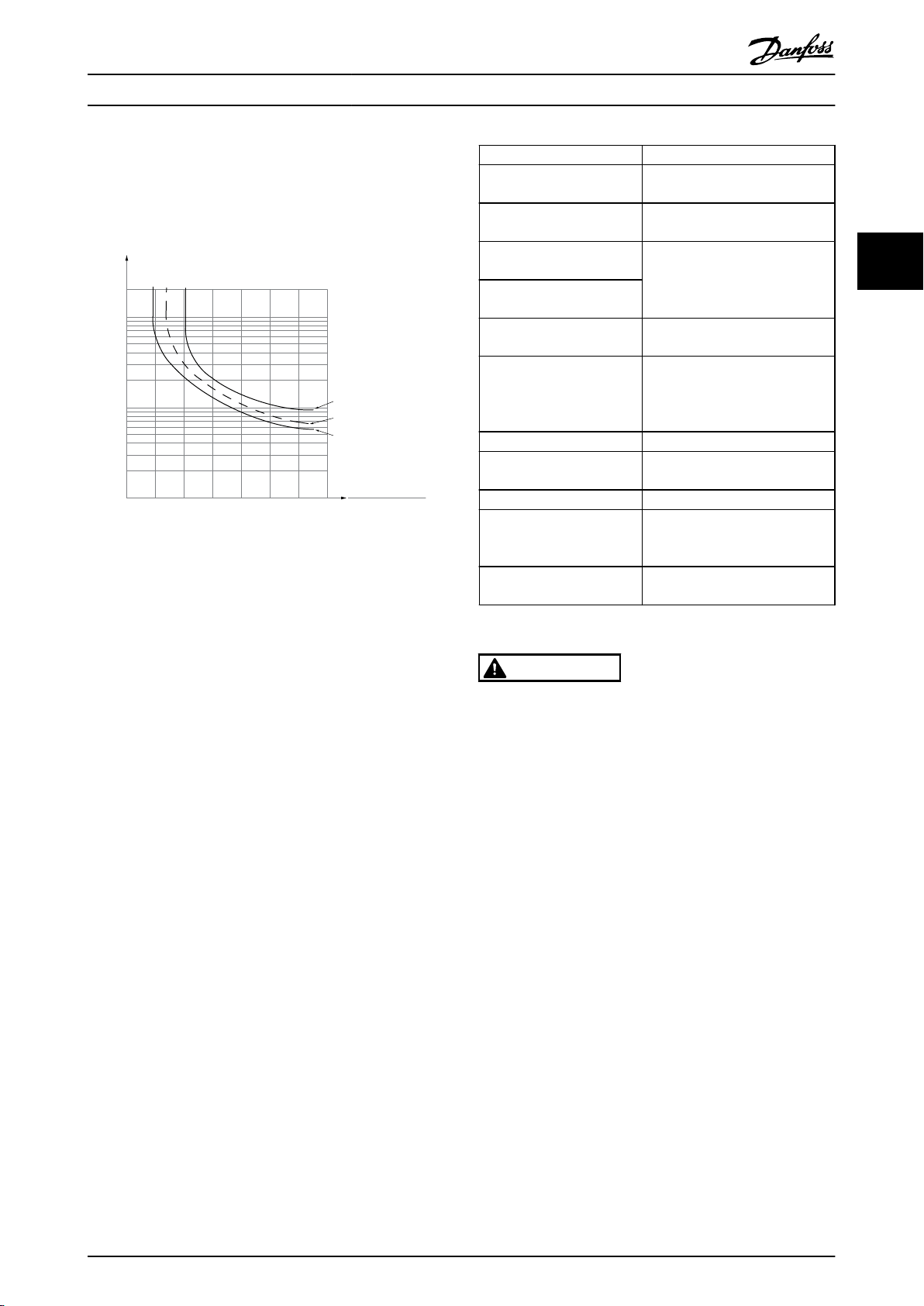
1.21.0 1.4
30
10
20
100
60
40
50
1.81.6 2.0
2000
500
200
400
300
1000
600
t [s]
175ZA052.12
f
OUT
= 2 x f
M,N
f
OUT
= 0.2 x f
M,N
f
OUT
= 1 x f
M,N
(par. 1-23)
IMN(par. 1-24)
I
M
Parameter Descriptions
VLT® AutomationDrive Programming Guide
3.3.10.3 ETR
The calculations estimate the need for a lower load at
speed due to less cooling from the fan incorporated
lower
in the motor.
Illustration 3.16 ETR Profile
3.3.10.4 ATEX ETR
Function Setting
1-90 Motor Thermal
Protection
1-94 ATEX ETR cur.lim. speed
reduction
1-98 ATEX ETR interpol.
freq.
points
1-99 ATEX ETR interpol
points
current
1-23 Motor Frequency
4-19 Max Output Frequency Motor name plate, possibly
4-18 Current Limit Forced to 150% by 1-90 [20]
5-15 Terminal 33 Digital
Input
5-19 Terminal 37 Safe Stop [4] PTC 1 Alarm
14-01 Switching Frequency Check that the default value fulfils
14-26 Trip Delay at Inverter
Fault
[20] ATEX ETR
20%
Motor name plate
Enter the same value as for
Max Output Frequency
4-19
for long motor cables,
reduced
sinus filter or reduced supply
voltage
[80] PTC Card 1
requirement from Motor name
the
plate. If not -use sine wave filter.
0
3 3
The B-option MCB 112 PTC Thermistor option offers ATEX
approved
monitoring of motor temperature. Alternatively,
an external ATEX approved PTC protection device can be
used.
NOTE
Only ATEX Ex-e approved motors may be used for this
function. See motor nameplate, approval certificate, data
sheet or contact motor supplier.
When controlling an Ex-e motor with “Increased Safety”, it
important to ensure certain limitations. The parameters
is
that must be programmed are presented in the following
application example.
MG33MF02 - VLT® is a registered Danfoss trademark
Table 3.8 Parameters
CAUTION
It is mandatory to compare the minimum switching
frequency
to the minimum switching frequency of the frequency
converter, the default value in 14-01 Switching Frequency. If
the frequency converter does not meet this requirement, a
sine wave filter must be used.
More information about ATEX ETR Thermal Monitoring can
be
3.3.10.5 Klixon
The Klixon type thermal circuit breaker uses a KLIXON
metal
by the current through the disc causes a trip.
Using a digital input and 24 V as power supply:
Example: The frequency converter trips when the motor
temperature is too high
Parameter set-up:
Set 1-90 Motor Thermal Protection to [2] Thermistor Trip
Set 1-93 Thermistor Source to [6] Digital Input
requirement stated by the motor manufacturer
found in the Application Note MN33G.
®
dish. At a predetermined overload, the heat caused
49
Page 51
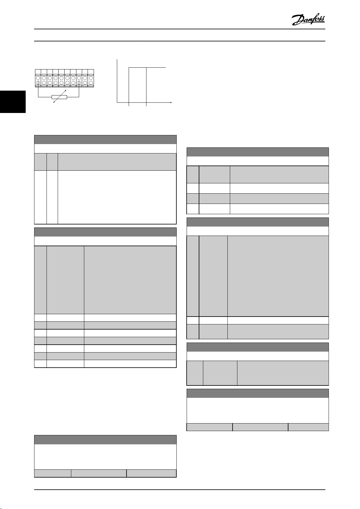
PTC / Thermistor
OFF
ON
+24V
12 13 18 3732
A
2719 29 33B20
GND
R<6.6 k Ω >10.8 k Ω
130BA151.11
Parameter Descriptions
VLT® AutomationDrive Programming Guide
The reaction for operating in Ex-e current limit must be
configured.
The frequency converter does not change anything
0%:
besides issuing warning 163 ATEX ETR cur.lim.warning.
>0%: The frequency converter issuing warning 163 and
reduces motor speed following ramp 2 (parameter group
33
3-5* Ramp 2).
Illustration 3.17
1-91 Motor External Fan
Option: Function:
[0] * No No external fan is required, i.e. the motor is derated at
low speed.
[1] Yes Applies an external motor fan (external ventilation), so
derating of the motor is required at low speed. The
no
upper curve in graph above (fout = 1 x fM,N) is
followed if the motor current is lower than nominal
motor current (see 1-24 Motor Current). If the motor
current exceeds nominal current, the operation time
still decreases as if no fan were installed.
1-93 Thermistor Source
Option: Function:
Select the input to which the thermistor
sensor) should be connected. An
(PTC
analog input option [1] or [2] cannot be
selected if the analog input is already in
use as a reference source (selected in
3-15 Reference 1 Source, 3-16 Reference 2
Source or 3-17 Reference 3 Source).
When using MCB 112, choice [0] None
must always be selected.
[0] * None
[1] Analog input 53
[2] Analog input 54
[3] Digital input 18
[4] Digital input 19
[5] Digital input 32
[6] Digital input 33
NOTE
parameter cannot be adjusted while the motor is
This
running.
NOTE
input should be set to [0] PNP - Active at 24 V in
Digital
5-00 Digital I/O Mode.
Example:
Actual reference = 50 RPM
1-94 ATEX ETR cur.lim. speed reduction = 20%
Resulting reference = 40 RPM
1-95 KTY Sensor Type
Option: Function:
Select the used type of KTY sensor. FC 302
only.
[0] * KTY Sensor 1
[1] KTY Sensor 2
[2] KTY Sensor 3
at 100 °C
1 kΩ
1 kΩ
at 25 °C
2 kΩ at 25 °C
1-96 KTY Thermistor Resource
Option: Function:
Selecting analog input terminal 54 to be used
KTY sensor input. Terminal 54 cannot be
as
selected as KTY source if otherwise used as
reference (see 3-15 Reference Resource 1 to
3-17 Reference Resource 3).
FC 302 only.
NOTE
Connection of KTY-sensor between term.
54 and 55 (GND). See Illustration 3.15.
[0] * None
[2] Analog
54
input
1-97 KTY Threshold level
Range: Function:
80 °C* [-40 - 140 °C] Select the KTY sensor threshold level for
thermal protection.
motor
FC 302 only.
1-98 ATEX ETR interpol. points freq.
FC 302 only.
visible if 1-90 Motor Thermal Protection is set to [20].
Only
Range: Function:
Size related* [ 0 - 1000.0 Hz]
0 %* [0 - 100 %]
50 MG33MF02 - VLT® is a registered Danfoss trademark
1-94 ATEX ETR cur.lim. speed reduction
FC 302 only.
visible if 1-90 Motor Thermal Protection is set to [20].
Only
Range: Function:
Enter the four frequency points [Hz] from the motor name
into this array. Together with 1-99 ATEX ETR interpol
plate
points current, these make up a table (f [Hz],I [%]).
Page 52

1 0 0 %
8 0 %
4 0 %
5 Hz 15 Hz 25 Hz 50 Hz
130BB909.10
Parameter Descriptions
VLT® AutomationDrive Programming Guide
NOTE
frequency/current limit points from the motor name
All
plate or motor data sheet must be programmed.
Illustration 3.18 Example of ATEX ETR thermal limitation curve.
x-axis:
fm [Hz]
y-axis: Im/I
x 100 [%]
m,n
3 3
1-98 ATEX ETR interpol. points
freq.
[0] = 5 Hz [0] = 40%
[1] = 15 Hz [1] = 80%
[2] = 25 Hz [2] = 100%
[3] = 50 Hz [3] = 100%
Table 3.9
operating points underneath the curve are allowed
All
1-99 ATEX ETR interpol
points
current
continuously. Above the line, however, only for a limited
time calculated as a function of the overload. In the event
of a machine current greater than 1.5 times the rated
current, shut down is immediate.
1-99 ATEX ETR interpol points current
FC 302 only.
Only
visible if 1-90 Motor Thermal Protection is set to [20] or [21].
Range: Function:
Size related* [0 - 100 %] Definition of thermal limitation curve.
example, see 1-98 ATEX ETR
For
interpol. points freq.
Use the four current points [A] from the motor name plate.
Calculate
current, Im/I
the values as percentage of nominal motor
x 100 [%], and enter into this array.
m,n
Together with 1-98 ATEX ETR interpol. points freq., these
make up a table (f [Hz],I [%]).
NOTE
All
frequency/current limit points from the motor name
plate or motor data sheet must be programmed.
MG33MF02 - VLT® is a registered Danfoss trademark
51
Page 53

Parameter Descriptions
VLT® AutomationDrive Programming Guide
3.4 Parameters: 2-** Brakes
3.4.1 2-0* DC-Brakes
Parameter group for configuring the DC brake and DC
functions.
hold
33
2-00 DC Hold Current
Range: Function:
50 %* [0 -
160.
Enter a value for holding current as a
%]
percentage of the rated motor current I
in 1-24 Motor Current. 100% DC holding current
corresponds to I
This parameter holds the motor function
(holding torque) or pre-heats the motor.
This parameter is active if DC hold is selected
in 1-72 Start Function [0] or 1-80 Function at
Stop [1].
M,N
.
M,N
set
NOTE
The
maximum value depends on the rated motor current.
Avoid 100 % current for too long. It may damage the
motor.
Low values of DC hold will produce larger than expected
currents with larger motor power sizes. This error will
increase as the motor power increases.
2-01 DC Brake Current
2-03 DC Brake Cut In Speed [RPM]
Range: Function:
set in 2-01
stop command.
DC Brake Current, upon a
2-04 DC Brake Cut In Speed [Hz]
Range: Function:
0.0 Hz* [0.0 - par. 4-14
Hz]
Set the DC brake cut-in speed for
activation
set in 2-01 DC Brake Current, upon a
stop command.
of the DC braking current
NOTE
2-04
DC Brake Cut In Speed [Hz] will not have effect when
1-10 Motor Construction = [1] PM, non salient SPM.
2-06 Parking Current
Range: Function:
50 %* [ 0 - 1000 %] Set current as percentage of rated motor
1-24 Motor Current. Will be used
current,
when enabled in 1-70 PM Start Mode.
2-07 Parking Time
Range: Function:
3 s* [0.1 - 60 s]
Set the duration of the Parking Current set in
Parking Current, once activated.
2-06
Range: Function:
50%* [0 -
1000.
Enter a value for current as a percentage of the
%]
rated motor current I
100% DC braking current corresponds to I
DC brake current is applied on a stop
command, when the speed is lower than the
limit set in 2-03 DC Brake Cut In Speed [RPM];
when the DC Brake Inverse function is active; or
via the serial communication port. The braking
current is active during the time period set in
2-02 DC Braking Time.
, see 1-24 Motor Current.
M,N
NOTE
The
maximum value depends on the rated motor current.
Avoid 100 % current for too long. It may damage the
motor.
2-02 DC Braking Time
Range: Function:
10.0 s* [0.0 - 60.0 s] Set the duration of the DC braking
current
set in 2-01 DC Brake Current, once
activated.
2-03 DC Brake Cut In Speed [RPM]
Range: Function:
0 RPM* [0 - par. 4-13
RPM]
Set the DC brake cut-in speed for
activation
of the DC braking current
M,N
.
3.4.2 2-1* Brake Energy Funct.
Parameter group for selecting dynamic braking parameters.
Only
valid for frequency converters with brake chopper.
2-10 Brake Function
Option: Function:
[0] * Off No brake resistor is installed.
[1] Resistor
brake
[2] AC brake Is selected to improve braking without using a
A brake resistor is incorporated in the system,
dissipation of surplus brake energy as heat.
for
Connecting a brake resistor allows a higher DC
link voltage during braking (generating
operation). The Resistor brake function is only
active in frequency converters with an integral
dynamic brake.
resistor. This parameter controls an
brake
overmagnetization of the motor when running
with a generatoric load. This function can
improve the OVC-function. Increasing the
electrical losses in the motor allows the OVC
function to increase the braking torque without
exceeding the over voltage limit. Please note
that AC brake is not as effective as dynamic
breaking with resistor.
AC brake is for VVC
open and closed loop.
plus
and flux mode in both
52 MG33MF02 - VLT® is a registered Danfoss trademark
Page 54

Parameter Descriptions
VLT® AutomationDrive Programming Guide
2-11 Brake Resistor (ohm)
Range: Function:
-
Size
related*
[ 5.00
65535.00
Ohm]
Set the brake resistor value in Ohms.
This value is used for monitoring the
power to the brake resistor in
2-13 Brake Power Monitoring. This
parameter is only active in frequency
converters with an integral dynamic
brake.
Use this parameter for values without
decimals. For a selection with two
decimals, use 30-81 Brake Resistor
(ohm).
2-12 Brake Power Limit (kW)
Range: Function:
Size
related*
[ 0.001
2000.000
kW]
-
2-12 Brake Power Limit (kW) is the expected
average power dissipated in the brake
resistor over a period of 120 s. It is used as
the monitoring limit for 16-33 Brake
Energy /2 min and thereby specifies when a
warning/ alarm is to be given.
To calculate 2-12 Brake Power Limit (kW),
the following formula can be used.
P
br,avg
P
the brake resistor, Rbr is the resistance of
the brake resistor. tbr is the active breaking
time within the 120 s period, Tbr.
Ubr is the DC voltage where the brake
resistor is active. This depends on the unit
as follows:
T2 units: 390 V
T4 units: 778 V
T5 units: 810 V
T6 units: 943 V/1099 V for D – F frames
T7 units: 1099 V
=
W
is the average power dissipated in
br,avg
NOTE
If
Rbr is not known or if Tbr is different
from 120 s, the practical approach is
to run the brake application, readout
16-33 Brake Energy /2 min and then
enter this + 20% in 2-12 Brake Power
Limit (kW).
2-13 Brake Power Monitoring
Option: Function:
This parameter is only active in frequency
converters
This parameter enables monitoring of the
power to the brake resistor. The power is
calculated on the basis of the resistance
with an integral dynamic brake.
2
U
V×tbrs
br
RbrΩ×Tbrs
2-13 Brake Power Monitoring
Option: Function:
Brake Resistor (ohm)), the DC link voltage,
(2-11
and the resistor duty time.
[0] * Off No brake power monitoring required.
[1] Warning Activates a warning on the display when the
transmitted over 120 s exceeds 100% of
power
the monitoring limit (2-12 Brake Power Limit
(kW) ).
The warning disappears when the transmitted
power falls below 80% of the monitoring limit.
[2] Trip Trips frequency converter and displays an
when the calculated power exceeds
alarm
100% of the monitoring limit.
[3] Warning
trip
and
If power monitoring is set to [0]
Activates both of the above, including
warning, trip and alarm.
Off or [1] Warning, the
brake function remains active, even if the monitoring limit
is exceeded. This may lead to thermal overload of the
resistor. It is also possible to generate a warning via a
relay/digital outputs. The measuring accuracy of the power
monitoring depends on the accuracy of the resistance of
the resistor (better than ±20%).
2-15 Brake Check
Option: Function:
Select type of test and monitoring function to
the connection to the brake resistor, or
check
whether a brake resistor is present, and then
display a warning or an alarm in the event of a
fault.
NOTE
The brake resistor disconnection function is
tested during power-up. However the brake
IGBT test is performed when there is no
braking. A warning or trip disconnects the
brake function.
The testing sequence is as follows:
The DC link ripple amplitude is
1.
measured for 300 ms without braking.
2. The DC link ripple amplitude is
measured for 300 ms with the brake
turned on.
3. If the DC link ripple amplitude while
braking is lower than the DC link ripple
amplitude before braking + 1%: Brake
check has failed by returning a warning
or alarm.
4. If the DC link ripple amplitude while
braking is higher than the DC link ripple
3 3
MG33MF02 - VLT® is a registered Danfoss trademark
53
Page 55

Parameter Descriptions
VLT® AutomationDrive Programming Guide
2-15 Brake Check
Option: Function:
amplitude before braking + 1%: Brake
is OK.
check
[0]*Off Monitors brake resistor and brake IGBT for a
33
[1] Warning Monitors brake resistor and brake IGBT for a
[2] Trip Monitors for a short-circuit or disconnection of
[3] Stop and
trip
[4] AC brake Monitors for a short-circuit or disconnection of
short-circuit
occurs, warning 25 appears.
short-circuit,
disconnection during power-up.
the
IGBT. If a fault occurs, the frequency converter
cuts out while displaying an alarm (trip locked).
Monitors for a short-circuit or disconnection of
the
IGBT. If a fault occurs, the frequency converter
ramps down to coast and then trips. A trip lock
alarm is displayed (e.g. warning 25, 27 or 28).
the
IGBT. If a fault occurs, the frequency converter
performs a controlled ramp-down. This option is
available for FC 302 only.
during operation. If a short-circuit
and runs a test for brake resistor
brake resistor, or a short-circuit of the brake
brake resistor, or a short-circuit of the brake
brake resistor, or a short-circuit of the brake
2-17 Over-voltage Control
Option: Function:
an over voltage on the DC link caused by
generative
[0] * Disabled No OVC required.
[1] Enabled (not
stop)
at
[2] Enabled Activates OVC.
Activates OVC except when using a stop
signal to stop the frequency converter.
power from the load.
NOTE
must not be enabled in hoisting applications.
OVC
2-18 Brake Check Condition
Range: Function:
[0] * At Power Up Brake check will be performed at power up
2-19 Over-voltage Gain
Range: Function:
100 %* [0 - 200 %] Select over-voltage gain.
3.4.3 2-2* Mechanical Brake
Parameters for controlling operation of an electromagnetic (mechanical) brake, typically required in hoisting
NOTE
Remove
Warning by cycling the mains supply. The fault must be
corrected first. For [0] Off or [1] Warning, the frequency
converter keeps running even if a fault is located.
a warning arising in connection with [0] Off or [1]
applications.
To control a mechanical brake, a relay output (relay 01 or
relay 02) or a programmed digital output (terminal 27 or
29) is required. Normally this output must be closed during
periods when the frequency converter is unable to ‘hold’
the motor, e.g. due to an excessive load. Select [32]
This parameter is only active in frequency converters with
integral dynamic brake.
an
2-16 AC brake Max. Current
Range: Function:
100.0 %* [0.0 - 1000.0 %] Enter the maximum permissible
when using AC brake to
current
avoid overheating of motor
windings.
Mechanical Brake Control for applications with an electromagnetic brake in 5-40 Function Relay, 5-30 Terminal 27
Digital Output, or 5-31 Terminal 29 Digital Output. When
selecting [32] Mechanical brake control, the mechanical
brake is closed from start up until the output current is
above the level selected in 2-20 Release Brake Current.
During stop, the mechanical brake activates when the
speed falls below the level specified in 2-21 Activate Brake
Speed [RPM]. If the frequency converter enters an alarm
condition or an over-current or over-voltage situation, the
NOTE
2-16 AC brake Max. Current will not have effect when
mechanical brake immediately cuts in. This is also the case
during safe stop.
1-10 Motor Construction = [1] PM, non salient SPM.
NOTE
2-17 Over-voltage Control
Option: Function:
Over-voltage control (OVC) reduces the risk
the frequency converter tripping due to
of
Protection
at Torque Limit and 14-26 Trip Delay at Inverter Fault) may
delay the activation of the mechanical brake in an alarm
condition. These features must be disabled in hoisting
applications.
mode and trip delay features (14-25 Trip Delay
54 MG33MF02 - VLT® is a registered Danfoss trademark
Page 56

Start
term.18
1=on
0=o
Shaft speed
Start delay time
on
o
Brake delay time
Time
Output current
Relay 01
Pre-magnetizing
current or
DC hold current
Reaction time EMK brake
Par 2-20
Release brake current
Par 1-76 Start current/
Par 2-00 DC hold current
Par 1-74
Start speed
Par 2-21
Activate brake
speed
Mechanical brake
locked
Mechanical brake
free
Par 1-71
Par 2-23
130BA074.12
Parameter Descriptions
VLT® AutomationDrive Programming Guide
3 3
Illustration 3.19 Mechanical Brake
2-20 Release Brake Current
Range: Function:
par.
16-37
A*
[0.00 par. 16-37
A]
Set the motor current for release of the
mechanical brake, when a start condition is
present. The default value is the maximum
current the inverter can provide for the
particular power size. The upper limit is
specified in 16-37 Inv. Max. Current.
NOTE
When Mechanical brake control output
is selected but no mechanical brake is
connected, the function will not work
by default setting due to too low
motor current.
2-21 Activate Brake Speed [RPM]
Range: Function:
0 RPM* [0 - 30000
RPM]
2-22 Activate Brake Speed [Hz]
Range: Function:
0 Hz* [0.0 - 5000.0 Hz] Set the motor frequency for activation
Set the motor speed for activation of
mechanical brake, when a stop
the
condition is present. The upper speed
limit is specified in 4-53 Warning Speed
High.
the mechanical brake, when a stop
of
condition is present.
MG33MF02 - VLT® is a registered Danfoss trademark
2-23 Activate Brake Delay
Range: Function:
0.0 s* [0.0 -
2-24 Stop Delay
Range: Function:
0.0 s* [0.0 - 5.0 s] Set the time interval from the moment
2-25 Brake Release Time
Range: Function:
0.20 s* [0.00 - 5.00s]This value defines the time it takes for
2-26 Torque Ref
Range: Function:
0.00 %* [0 - 0 %] The value defines the torque applied against
5.0
Enter the brake delay time of the coast after
s]
ramp-down time. The shaft is held at zero
speed with full holding torque. Ensure that the
mechanical brake has locked the load before
the motor enters coast mode. See Mechanical
Brake Control section in the Design Guide.
the motor is stopped until the brake
when
closes. This parameter is a part of the
stopping function.
mechanical brake to open. This
the
parameter must act as a time-out when
brake feedback is activated.
closed mechanical brake, before release
the
55
Page 57

Mech.
Brake
Gain
Boost
Relay
Torque
ref.
Motor
Speed
Premag Torque Ramp
Time
p. 2-27
Torque Ref. 2-26
Gain Boost Factor
p. 2-28
Brake
Release
Time
p. 2-25
Ramp 1 up
p. 3-41
Ramp 1 down
p. 3-42
Stop
Delay
p. 2-24
Activate
Brake
Delay
p. 2-23
1 2 3
130BA642.12
II
I
Parameter Descriptions
VLT® AutomationDrive Programming Guide
2-27 Torque Ramp Time
Range: Function:
0.2 s* [0.0 - 5.0 s] The value defines the duration of the torque
in clockwise direction.
ramp
2-28 Gain Boost Factor
Range: Function:
1.00 N/A* [1.00 - 4.00
N/A]
Only active in flux closed loop. The
function
ensures a smooth transition
from torque control mode to speed
33
control mode when the motor takes
over the load from the brake.
Illustration 3.20 Brake release sequence for hoist mechanical brake control
Activate brake delay: The frequency converter starts again from the mechanical brake engaged position.
I)
II) Stop delay: When the time between successive starts is shorter than the setting in 2-24 Stop Delay, the frequency converter starts
without applying the mechanical brake (e.g. reversing).
56 MG33MF02 - VLT® is a registered Danfoss trademark
Page 58

Parameter Descriptions
VLT® AutomationDrive Programming Guide
3.5 Parameters: 3-** Reference/Ramps
Parameters for reference handling, definition of limitations,
configuration of the reaction of the frequency
and
converter to changes.
3.5.1 3-0* Reference Limits
3-00 Reference Range
Option: Function:
Select the range of the reference signal and the
feedback
only, or positive and negative. The minimum
limit may have a negative value, unless [1] Speed
closed loop control or [3] Process is selected in
1-00 Configuration Mode.
[0] Min -
Max
[1] * -Max -
+Max
Select the range of the reference signal and the
feedback
only, or positive and negative. The minimum
limit may have a negative value, unless [1] Speed
closed loop control or [3] Process is selected in
1-00 Configuration Mode.
For both positive and negative values (both
directions,
3-01 Reference/Feedback Unit
Option: Function:
Select the unit to be used in Process PID Control
references
Mode must be either [3] Process or [8] Extended
PID Control.
[0] * None
[1] %
[2] RPM
[3] Hz
[4] Nm
[5] PPM
[10] 1/min
[12] Pulse/s
[20] l/s
[21] l/min
[22] l/h
[23] m³/s
[24] m³/min
[25] m³/h
[30] kg/s
[31] kg/min
[32] kg/h
[33] t/min
[34] t/h
[40] m/s
[41] m/min
[45] m
[60] °C
signal. Signal values can be positive
signal. Signal values can be positive
relative to 4-10 Motor Speed Direction).
and feedbacks. 1-00 Configuration
3-01 Reference/Feedback Unit
Option: Function:
[70] mbar
[71] bar
[72] Pa
[73] kPa
[74] m WG
[80] kW
[120] GPM
[121] gal/s
[122] gal/min
[123] gal/h
[124] CFM
[125] ft³/s
[126] ft³/min
[127] ft³/h
[130] lb/s
[131] lb/min
[132] lb/h
[140] ft/s
[141] ft/min
[145] ft
[150] lb ft
[160] °F
[170] psi
[171] lb/in²
[172] in WG
[173] ft WG
[180] HP
3-02 Minimum Reference
Range: Function:
0 ReferenceFeedbackUnit*
[-999999.999 -
3-03
par.
ReferenceFeedbackUnit]
Enter the Minimum
Reference. The Minimum
Reference is the lowest
value obtainable by
summing all references.
Minimum Reference is active
only when 3-00 Reference
Range is set to [0] Min.- Max.
The Minimum Reference
unit matches:
•
•
3 3
The choice of
configuration in
1-00 Configuration
Mode Configuration
Mode: for [1] Speed
closed loop, RPM;
for [2] Torque, Nm.
The unit selected
in 3-01 Reference/
Feedback Unit.
MG33MF02 - VLT® is a registered Danfoss trademark
57
Page 59

[P 5-13=Preset ref. bit 0]
Preset
[P 5-14=Preset ref. bit 1]
[P 5-15=Preset ref. bit 2]
10101010
76543210
29
12
(+24V)
11001100
32
11110000
33
130BA149.10
Parameter Descriptions
VLT® AutomationDrive Programming Guide
3-03 Maximum Reference
Range: Function:
1500.000
ReferenceFeedbackUnit*
33
3-04 Reference Function
Option: Function:
[0] * Sum Sums both external and preset reference
[1] External/Preset Use either the preset or the external
3.5.2 3-1* References
[par. 3-02 -
999999.999
ReferenceFeedbackUnit]
sources.
reference
Shift between external and preset via a
command or a digital input.
Enter the Maximum
Reference.
Reference is the highest
value obtainable by
summing all references.
The Maximum Reference
unit matches:
The choice of
•
configuration in
1-00 Configuration
Mode: for [1] Speed
closed loop, RPM;
for [2] Torque, Nm.
The unit selected
•
in 3-00 Reference
Range.
source.
The Maximum
Illustration 3.21
Preset ref. bit 2 1 0
Preset ref. 0 0 0 0
Preset ref. 1 0 0 1
Preset ref. 2 0 1 0
Preset ref. 3 0 1 1
Preset ref. 4 1 0 0
Preset ref. 5 1 0 1
Preset ref. 6 1 1 0
Preset ref. 7 1 1 1
Table 3.10 Preset Ref. Bit
3-11 Jog Speed [Hz]
Range: Function:
0 Hz* [0.0 - par.
Hz]
4-14
The jog speed is a fixed output speed at
which the frequency converter is running
when the jog function is activated.
See also 3-80 Jog Ramp Time.
Select the preset reference(s). Select Preset ref. bit 0/1/2
[16],
[17] or [18] for the corresponding digital inputs in
parameter group 5-1*.
3-10 Preset Reference
Array [8]
0-7
Range:
Range: Function:
0.00%* [-100.00 -
100.00
Enter up to eight different preset references
%]
(0-7) in this parameter, using array
programming. The preset reference is stated
as a percentage of the value Ref
(3-03 Maximum Reference) If a Ref
different from 0 (3-02 Minimum Reference) is
programmed, the preset reference is
calculated as a percentage of the full
reference range, i.e. on the basis of the
difference between Ref
Afterwards, the value is added to Ref
When using preset references, select Preset
ref. bit 0/1/2 [16], [17] or [18] for the
corresponding digital inputs in parameter
group 5-1*.
MAX
and Ref
MAX
MIN
MIN
.
MIN
3-12 Catch up/slow Down Value
Range: Function:
0.00%* [0.00 -
100.00
.
Enter a percentage (relative) value to be
%]
either added to or deducted from the actual
reference for Catch up or Slow down respectively. If Catch up is selected via one of the
digital inputs (5-10 Terminal 18 Digital Input to
5-15 Terminal 33 Digital Input), the percentage
(relative) value is added to the total reference.
If Slow down is selected via one of the digital
inputs (5-10 Terminal 18 Digital Input to
5-15 Terminal 33 Digital Input), the percentage
(relative) value is deducted from the total
reference. Obtain extended functionality with
the DigiPot function. See parameter group
3-9* Digital Potentiometer.
58 MG33MF02 - VLT® is a registered Danfoss trademark
Page 60

Relative
Z=X+X*Y/100
Resulting
actual
reference
Y
X
130BA059.12
Z
X
100
%
0-100
Z
Y
X+X*Y/100
P 3-14
130BA278.10
Parameter Descriptions
VLT® AutomationDrive Programming Guide
3-13 Reference Site
Option: Function:
Select which reference site to activate.
[0] * Linked to
/ Auto
Hand
[1] Remote Use remote reference in both Hand mode
[2] Local Use local reference in both Hand mode and
Use local reference when in Hand mode; or
remote reference when in Auto mode.
Auto mode.
and
mode.
Auto
NOTE
When set to [2] Local, the frequency
converter will start with this setting
again following a 'power down'.
3-14 Preset Relative Reference
Range: Function:
0.00%* [-100.00 -
100.00
Illustration 3.22
The actual reference, X, is increased or
%]
decreased with the percentage Y, set in
3-14 Preset Relative Reference. This results
in the actual reference Z. Actual reference
(X) is the sum of the inputs selected in
3-15 Reference 1 Source, 3-16 Reference 2
Source, 3-17 Reference 3 Source and
8-02 Control Source.
3-15 Reference Resource 1
Option: Function:
sum of these reference signals
the actual reference.
defines
[0] No function
[1] * Analog input 53
[2] Analog input 54
[7] Frequency input 29
[8] Frequency input 33
[11] Local bus reference
[20] Digital pot.meter
[21] Analog input X30-11 (General Purpose I/O Option Module)
[22] Analog input X30-12 (General Purpose I/O Option Module)
3-16 Reference Resource 2
Option: Function:
Select the reference input to be
for the second reference
used
signal. 3-15 Reference Resource 1,
3-16 Reference Resource 2 and
3-17 Reference Resource 3 define up
to three different reference signals.
The sum of these reference signals
defines the actual reference.
[0] No function
[1] Analog input 53
[2] Analog input 54
[7] Frequency input 29
[8] Frequency input 33
[11] Local bus reference
[20] * Digital pot.meter
[21] Analog input X30-11
[22] Analog input X30-12
3 3
Illustration 3.23
3-15 Reference Resource 1
Option: Function:
Select the reference input to be used
the first reference signal.
for
3-15 Reference Resource 1,
3-16 Reference Resource 2 and
3-17 Reference Resource 3 define up to
three different reference signals. The
3-17 Reference Resource 3
Option: Function:
[0] No function
[1] Analog input 53
[2] Analog input 54
[7] Frequency input 29
[8] Frequency input 33
[11] * Local bus reference
MG33MF02 - VLT® is a registered Danfoss trademark
[20] Digital pot.meter
[21] Analog input X30-11
[22] Analog input X30-12
Select the reference input to be
for the third reference signal.
used
3-15 Reference Resource 1,
3-16 Reference Resource 2 and
3-17 Reference Resource 3 define up
to three different reference signals.
The sum of these reference signals
defines the actual reference.
59
Page 61
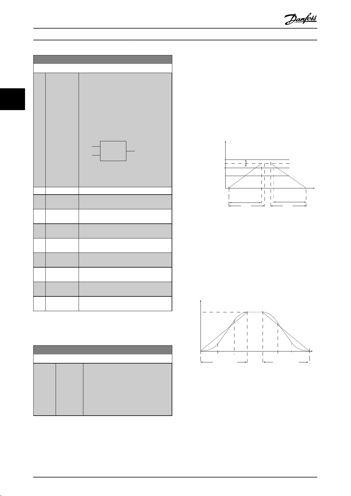
Relative
Z=X+X*Y/100
Resulting
actual
reference
Y
X
130BA059.12
Z
P 3-*2
Ramp (X) Down
Time (Dec)
P 4-13
High-limit
RPM
Reference
n
s
P 4-11
Low limit
t
dec
Time
P 3-*1
Ramp (X)Up
Time (Acc)
t
acc
130BA872.10
130BA168.10
Ramp (X) S-Ramp
Ratio at Accel.End
Jerk compensated
Ramp (X)
Up Time
Ramp (X)
S-Ramp
Ratio at
Accel.End
Linear
Speed
Ramp (X)
Down Time
Ramp (X)
S-Ramp
Ratio at
Dec.End
Ramp (X) S-Ramp
Ratio at Dec.End
Parameter Descriptions
VLT® AutomationDrive Programming Guide
3-18 Relative Scaling Reference Resource
Option: Function:
Select a variable value to be added to the
value (defined in 3-14 Preset Relative
fixed
Reference). The sum of the fixed and
33
variable values (labelled Y in the illustration
below) is multiplied with the actual
3.5.3 Ramps
Ramp 1
3-4*
For each of four ramps (parameter groups 3-4*, 3-5*, 3-6*
and
3-7*) configure the ramp parameters: ramp type,
ramping times (duration of acceleration and deceleration)
and level of jerk compensation for S ramps.
reference (labelled X in the illustration
below). This product is then added to the
actual reference (X+X*Y/100) to give the
Start by setting the linear ramping times corresponding to
the figures.
resultant actual reference.
Illustration 3.24
[0] * No function
[1] Analog input
53
[2] Analog input
Illustration 3.25
54
[7] Frequency
29
input
[8] Frequency
33
input
[11] Local bus
reference
[20] Digital
pot.meter
If S-ramps are selected then set the level of non-linear jerk
compensation
required. Set jerk compensation by defining
the proportion of ramp-up and ramp-down times where
acceleration and deceleration are variable (i.e. increasing or
decreasing). The S-ramp acceleration and deceleration
settings are defined as a percentage of the actual ramp
time.
[21] Analog input
X30-11
[22] Analog input
X30-12
NOTE
This
parameter cannot be adjusted while the motor is
running.
3-19 Jog Speed [RPM]
Range: Function:
150.
RPM*
[0 - par.
RPM]
4-13
Enter a value for the jog speed n
which is a fixed output speed. The
frequency converter runs at this speed
when the jog function is activated. The
maximum limit is defined in 4-13 Motor
Speed High Limit [RPM].
See also 3-80 Jog Ramp Time.
60 MG33MF02 - VLT® is a registered Danfoss trademark
JOG
,
Illustration 3.26
Page 62

Parameter Descriptions
VLT® AutomationDrive Programming Guide
3-40 Ramp 1 Type
Option: Function:
Select the ramp type, depending on
for acceleration/deceleration.
[0] * Linear
[1] S-ramp
Const
[2] S-ramp
Const
Jerk
Time
requirements
A linear ramp will give constant acceleration
during ramping. An S-ramp will give nonlinear acceleration, compensating for jerk in
the application.
Acceleration with lowest possible jerk.
S-ramp based on the values set in 3-41 Ramp
1 Ramp up Time and 3-42 Ramp 1 Ramp Down
Time.
NOTE
If
[1] S-ramp Const Jerk is selected and the reference during
ramping is changed the ramp time may be prolonged in
order to realize a jerk free movement which may result in
a longer start or stop time.
Additional adjustment of the S-ramp ratios or switching
initiators may be necessary.
3-41 Ramp 1 Ramp up Time
Range: Function:
3.00s* [0.01 -
3600.00
3-42 Ramp 1 Ramp Down Time
Range: Function:
3.00s* [0.01 -
3600.00
s]
3-45 Ramp 1 S-ramp Ratio at Accel. Start
Range: Function:
50 %* [1 - 99.%]Enter the proportion of the total ramp-up
Enter the ramp-up time, i.e. the acceleration
s]
time from 0 RPM to the synchronous motor
speed nS. Choose a ramp-up time such that
the output current does not exceed the
current limit in 4-18 Current Limit during
ramping. The value 0.00 corresponds to 0.01 s
in speed mode. See ramp-down time in
3-42 Ramp 1 Ramp Down Time.
t
s x
n
ref RPM
s x n
ref RPM
RPM
s
RPM
s
Par
. 3 − 41 =
Enter the ramp-down time, that is, the
deceleration
speed ns to 0 RPM. Choose a ramp-down time
such that no over-voltage arises in the inverter
due to regenerative operation of the motor,
and such that the generated current does not
exceed the current limit set in 4-18 Current
Limit. The value 0.00 corresponds to 0.01 s in
speed mode. See ramp-up time in 3-41 Ramp 1
Ramp up Time.
Par
. 3 − 42 =
time
acc
time from the synchronous motor
t
dec
(3-41 Ramp 1 Ramp up Time) in which
3-45 Ramp 1 S-ramp Ratio at Accel. Start
Range: Function:
the acceleration torque increases. The larger
percentage value, the greater the jerk
the
compensation achieved, and thus the lower
the torque jerks occurring in the application.
3-46 Ramp 1 S-ramp Ratio at Accel. End
Range: Function:
50 %* [1 - 99. %] Enter the proportion of the total ramp-up
(3-41 Ramp 1 Ramp up Time) in which
time
the acceleration torque decreases. The larger
the percentage value, the greater the jerk
compensation achieved, and thus the lower
the torque jerks in the application.
3-47 Ramp 1 S-ramp Ratio at Decel. Start
Range: Function:
50 %* [1 - 99. %] Enter the proportion of the total ramp-down
(3-42 Ramp 1 Ramp Down Time) where
time
the deceleration torque increases. The larger
the percentage value, the greater the jerk
compensation achieved, and thus the lower
the torque jerks in the application.
3-48 Ramp 1 S-ramp Ratio at Decel. End
Range: Function:
50 %* [1 - 99. %] Enter the proportion of the total ramp-down
(3-42 Ramp 1 Ramp Down Time) where
time
the deceleration torque decreases. The larger
the percentage value, the greater the jerk
compensation achieved, and thus the lower
the torque jerks in the application.
3.5.4 3-5* Ramp 2
Choosing ramp parameters, see parameter group 3-4*.
3-50 Ramp 2 Type
Option: Function:
Select the ramp type, depending on
for acceleration/deceleration. A
[0] * Linear
[1] S-ramp
Const
[2] S-ramp
Const
Jerk
Time
requirements
linear ramp will give constant acceleration
during ramping. An S-ramp will give nonlinear acceleration, compensating for jerk in
the application.
Acceleration with lowest possible jerk
S-ramp based on the values set in 3-51 Ramp
2 Ramp up Time and 3-52 Ramp 2 Ramp down
Time
3 3
MG33MF02 - VLT® is a registered Danfoss trademark
61
Page 63

Parameter Descriptions
VLT® AutomationDrive Programming Guide
NOTE
[1] S-ramp Const Jerk is selected and the reference during
If
ramping is changed the ramp time may be prolonged in
order to realize a jerk free movement which may result in
a longer start or stop time.
Additional adjustment of the S-ramp ratios or switching
33
initiators may be necessary.
3-57 Ramp 2 S-ramp Ratio at Decel. Start
Range: Function:
50 %* [1 - 99. %] Enter the proportion of the total ramp-down
(3-52 Ramp 2 Ramp down Time) where
time
the deceleration torque increases The larger
the percentage value, the greater the jerk
compensation achieved, and thus the lower
the torque jerks in the application.
3-51 Ramp 2 Ramp up Time
Range: Function:
3.00s* [0.01 -
3600.00
Enter the ramp-up time, i.e. the acceleration
s]
time from 0 RPM to the rated motor speed ns.
Choose a ramp-up time such that the output
current does not exceed the current limit in
4-18 Current Limit during ramping. The value
0.00 corresponds to 0.01 s in speed mode.
See ramp-down time in 3-52 Ramp 2 Ramp
down Time.
t
s x n
Par
. 3 − 51 =
acc
ref RPM
s
3-52 Ramp 2 Ramp down Time
Range: Function:
3.00s* [0.01 -
3600.00
s]
Enter the ramp-down time, i.e. the
deceleration
ns to 0 RPM. Choose a ramp-down time such
that no over-voltage arises in the inverter due
to regenerative operation of the motor, and
such that the generated current does not
exceed the current limit set in 4-18 Current
Limit. The value 0.00 corresponds to 0.01 s in
speed mode. See ramp-up time in 3-51 Ramp 2
Ramp up Time.
Par
. 3 − 52 =
time from the rated motor speed
t
s x n
dec
ref RPM
s
3-55 Ramp 2 S-ramp Ratio at Accel. Start
RPM
RPM
3-58 Ramp 2 S-ramp Ratio at Decel. End
Range: Function:
50 %* [1 - 99. %] Enter the proportion of the total ramp-down
time
(3-52 Ramp 2 Ramp down Time) where
the deceleration torque decreases. The larger
the percentage value, the greater the jerk
compensation achieved, and thus the lower
the torque jerks in the application.
3.5.5 3-6* Ramp 3
Configure ramp parameters, see 3-4*.
3-60 Ramp 3 Type
Option: Function:
Select the ramp type, depending on
for acceleration and
[0] * Linear
[1] S-ramp
Const
[2] S-ramp
Const
Jerk
Time
requirements
deceleration. A linear ramp will give constant
acceleration during ramping. An S-ramp will
give non-linear acceleration, compensating
for jerk in the application.
Accelerates with lowest possible jerk.
S-ramp based on the values set in 3-61 Ramp
3 Ramp up Time and 3-62 Ramp 3 Ramp down
Time
Range: Function:
50 %* [1 - 99. %] Enter the proportion of the total ramp-up
(3-51 Ramp 2 Ramp up Time) in which
time
the acceleration torque increases. The larger
the percentage value, the greater the jerk
compensation achieved, and thus the lower
the torque jerks in the application.
NOTE
If
[1] S-ramp Const Jerk is selected and the reference during
ramping is changed the ramp time may be prolonged in
order to realize a jerk free movement which may result in
a longer start or stop time.
Additional adjustment of the S-ramp ratios or switching
initiators may be necessary.
3-56 Ramp 2 S-ramp Ratio at Accel. End
Range: Function:
50 %* [1 - 99. %] Enter the proportion of the total ramp-up
(3-51 Ramp 2 Ramp up Time) in which
time
the acceleration torque decreases. The larger
the percentage value, the greater the jerk
compensation achieved, and thus the lower
the torque jerks in the application.
3-61 Ramp 3 Ramp up Time
Range: Function:
3.00 s* [0.01 -
3600.00
Enter the ramp-up time, i.e. the
s]
acceleration time from 0 RPM to the rated
motor speed ns. Choose a ramp-up time
such that the output current does not
exceed the current limit in 4-18 Current
Limit during ramping. The value 0.00
corresponds to 0.01 s in speed mode. See
62 MG33MF02 - VLT® is a registered Danfoss trademark
Page 64

Parameter Descriptions
VLT® AutomationDrive Programming Guide
3-61 Ramp 3 Ramp up Time
Range: Function:
ramp-down time in 3-62
down Time.
Ramp 3 Ramp
3-62 Ramp 3 Ramp down Time
Range: Function:
3.00s* [0.01 -
3600.00
s]
Enter the ramp-down time, i.e. the
deceleration
ns to 0 RPM. Choose a ramp-down time such
that no over-voltage arises in the inverter due
to regenerative operation of the motor, and
such that the generated current does not
exceed the current limit set in 4-18 Current
Limit. The value 0.00 corresponds to 0.01 s in
speed mode. See ramp-up time in 3-61 Ramp 3
Ramp up Time.
Par
. 3 − 62 =
time from the rated motor speed
t
s x n
ref RPM
RPM
s
dec
3-65 Ramp 3 S-ramp Ratio at Accel. Start
Range: Function:
50 %* [1 - 99. %] Enter the proportion of the total ramp-up
(3-61 Ramp 3 Ramp up Time) in which
time
the acceleration torque increases. The larger
the percentage value, the greater the jerk
compensation achieved, and thus the lower
the torque jerks in the application.
3-66 Ramp 3 S-ramp Ratio at Accel. End
Range: Function:
50 %* [1 - 99. %] Enter the proportion of the total ramp-up
(3-61 Ramp 3 Ramp up Time) in which
time
the acceleration torque decreases. The larger
the percentage value, the greater the jerk
compensation achieved, and thus the lower
the torque jerks in the application.
3-68 Ramp 3 S-ramp Ratio at Decel. End
Range: Function:
50 %* [1 - 99. %] Enter the proportion of the total ramp-
downdecel
Time) where the deceleration torque
decreases. The larger the percentage value,
the greater the jerk compensation achieved,
and thus the lower the torque jerks in the
application.
time (3-62 Ramp 3 Ramp down
3.5.6 3-7* Ramp 4
Configure ramp parameters, see parameter group 3-4*.
3-70 Ramp 4 Type
Option: Function:
Select the ramp type, depending on
for acceleration and
[0] * Linear
[1] S-ramp
Const
[2] S-ramp
Const
Jerk
Time
requirements
deceleration. A linear ramp will give constant
acceleration during ramping. An S-ramp will
give non-linear acceleration, compensating
for jerk in the application
Accelerates with lowest possible jerk.
S-ramp based on the values set in 3-71 Ramp
4 Ramp up Time and 3-72 Ramp 4 Ramp Down
Time.
NOTE
[1] S-ramp Const Jerk is selected and the reference during
If
ramping is changed the ramp time may be prolonged in
order to realize a jerk free movement which may result in
a longer start or stop time.
Additional adjustment of the S-ramp ratios or switching
initiators may be necessary.
3 3
3-67 Ramp 3 S-ramp Ratio at Decel. Start
Range: Function:
50 %* [1 - 99. %] Enter the proportion of the total ramp-down
(3-62 Ramp 3 Ramp down Time) where
time
the deceleration torque increases. The larger
the percentage value, the greater the jerk
compensation achieved, and thus the lower
the torque jerks in the application.
MG33MF02 - VLT® is a registered Danfoss trademark
3-71 Ramp 4 Ramp up Time
Range: Function:
3.00s* [0.01 -
3600.00
Enter the ramp-up time, i.e. the acceleration
s]
time from 0 RPM to the rated motor speed ns.
Choose a ramp-up time such that the output
current does not exceed the current limit in
4-18 Current Limit during ramping. The value
0.00 corresponds to 0.01 s in speed mode.
See ramp-down time in 3-72 Ramp 4 Ramp
Down Time.
Par
. 3 − 71 =
3-72 Ramp 4 Ramp Down Time
Range: Function:
3.00s* [0.01 -
3600.00
s]
Enter the ramp-down time, i.e. the
deceleration
ns to 0 RPM. Choose a ramp-down time such
time from the rated motor speed
t
acc
s x n
ref RPM
RPM
s
63
Page 65

130BA070.10
Time
P 3-80
RPM
P 4-13 RPM
high limit
P 1-25
Motor speed
Jog speed
P 3-19
P 3-80
Ramp up
(acc)
Ramp down
(dec)
t jog t jog
P 4-11 RPM
low limit
Parameter Descriptions
VLT® AutomationDrive Programming Guide
33
3-72 Ramp 4 Ramp Down Time
Range: Function:
3-80 Jog Ramp Time
Range: Function:
that no over-voltage arises in the inverter due
regenerative operation of the motor, and
to
such that the generated current does not
exceed the current limit set in 4-18 Current
Limit. The value 0.00 corresponds to 0.01 s in
speed mode. See ramp-up time in 3-71 Ramp 4
Ramp up Time.
t
s x n
Par
. 3 − 72 =
dec
ref RPM
RPM
s
3-75 Ramp 4 S-ramp Ratio at Accel. Start
Range: Function:
50 %* [1 - 99. %] Enter the proportion of the total ramp-up
(3-71 Ramp 4 Ramp up Time) in which
time
the acceleration torque increases. The larger
the percentage value, the greater the jerk
compensation achieved, and thus the lower
the torque jerks in the application.
3-76 Ramp 4 S-ramp Ratio at Accel. End
Range: Function:
50 %* [1 - 99. %] Enter the proportion of the total ramp-up
(3-71 Ramp 4 Ramp up Time) in which
time
the acceleration torque decreases. The larger
Illustration 3.27
the percentage value, the greater the jerk
compensation achieved, and thus the lower
the torque jerks in the application.
3-77 Ramp 4 S-ramp Ratio at Decel. Start
Range: Function:
50 %* [1 - 99. %] Enter the proportion of the total ramp-down
(3-72 Ramp 4 Ramp Down Time) where
time
Par
. 3 − 80 =
3-81 Quick Stop Ramp Time
Range: Function:
3.00s* [0.01 -
3600.00
jog speed
Δ
s]
t
the deceleration torque increases. The larger
the percentage value, the greater the jerk
compensation achieved, and thus the lower
the torque jerks in the application.
3-78 Ramp 4 S-ramp Ratio at Decel. End
Range: Function:
50 %* [1 - 99. %] Enter the proportion of the total ramp-down
(3-72 Ramp 4 Ramp Down Time) where
time
the deceleration torque decreases. The larger
the percentage value, the greater the jerk
compensation achieved, and thus the lower
the torque jerks in the application.
3.5.7 3-8* Other Ramps
3-80 Jog Ramp Time
Range: Function:
3.00s* [0.01 -
3600.00
64 MG33MF02 - VLT® is a registered Danfoss trademark
Enter the jog ramp time, i.e. the
s]
acceleration/deceleration time between 0
RPM and the rated motor frequency ns.
that the resultant output current
Ensure
required for the given jog ramp time does
not exceed the current limit in 4-18 Current
Limit. The jog ramp time starts upon
activation of a jog signal via the LCP, a
selected digital input, or the serial communication port. When jog state is disabled then
the normal ramping times are valid.
s x n
(
par
RPM
s
. 3 − 19)
RPM
jog
Enter the quick–stop ramp-down time, i.e.
the deceleration time from the synchronous
motor speed to 0 RPM. Ensure that no
resultant over-voltage will arise in the
inverter due to regenerative operation of the
motor required to achieve the given rampdown time. Ensure also that the generated
current required to achieve the given rampdown time does not exceed the current limit
(set in 4-18 Current Limit). Quick-stop is
activated by means of a signal on a selected
digital input, or via the serial communication
port.
Page 66

130BA069.10
Time
RPM
P 4-13 RPM
high limit
Reference
P 1-25
Motor speed
low limit
P 4-11 RPM
P 3-81
Qramp
Qstop
Speed
Time (s)
Inc
130BA158.11
P 3-95
Speed
Time (s)
Dec
Inc
130BA159.11
P 3-95
Parameter Descriptions
VLT® AutomationDrive Programming Guide
3.5.8 3-9* Digital Pot.Meter
The digital potentiometer function allows the user to
increase
set-up of the digital inputs using the functions Increase,
Decrease or Clear. To activate the function, at least one
digital input must be set up to Increase or Decrease.
or decrease the actual reference by adjusting the
3 3
Illustration 3.28
3-82 Quick Stop Ramp Type
Option: Function:
Select the ramp type, depending on
requirements
deceleration. A linear ramp will give
constant acceleration during ramping. An
S-ramp will give non-linear acceleration,
compensating for jerk in the application.
[0] * Linear
[1] S-ramp Const
Jerk
[2] S-ramp Const
Time
for acceleration and
3-83 Quick Stop S-ramp Ratio at Decel. Start
Range: Function:
50 %* [ 1
- 99%]Enter the proportion of the total ramp-down
time (3-42 Ramp 1 Ramp Down Time) where
the deceleration torque increases. The larger
the percentage value, the greater the jerk
compensation achieved, and thus the lower
the torque jerks in the application.
3-84 Quick Stop S-ramp Ratio at Decel. End
Range: Function:
50 %* [ 1 - 99 %] Enter the proportion of the total ramp-down
(3-42 Ramp 1 Ramp Down Time) where
time
the deceleration torque decreases. The larger
the percentage value, the greater the jerk
compensation achieved, and thus the lower
the torque jerks in the application.
MG33MF02 - VLT® is a registered Danfoss trademark
Illustration 3.29
Illustration 3.30
3-90 Step Size
Range: Function:
0.10 %* [0.01 -
200.00 %]
Enter the increment size required for
INCREASE/DECREASE, as a percentage of
the synchronous motor speed, ns. If
INCREASE/DECREASE is activated the
resulting reference will be increased/
decreased by the amount set in this
parameter.
3-91 Ramp Time
Range: Function:
1.00s* [0.00 -
3600.00 s]
Enter the ramp time, i.e. the time for
adjustment of the reference from 0% to
100% of the specified digital potentiometer
function (Increase, Decrease or Clear).
If Increase/ Decrease is activated for longer
than the ramp delay period specified in
3-95 Ramp Delay the actual reference will be
ramped up / down according to this ramp
time. The ramp time is defined as the time
used to adjust the reference by the step size
specified in 3-90 Step Size.
65
Page 67

Parameter Descriptions
VLT® AutomationDrive Programming Guide
3-92 Power Restore
Option: Function:
[0] * Off Resets the Digital Potentiometer reference to 0% after
up.
power
[1] On Restores the most recent Digital Potentiometer
33
reference
at power up.
3-93 Maximum Limit
Range: Function:
100 %* [-200 - 200%]Set the maximum permissible value for
resultant reference. This is advisable if
the
the Digital Potentiometer is used for fine
tuning of the resulting reference.
3-94 Minimum Limit
Range: Function:
-100 %* [-200 - 200%]Set the minimum permissible value for
resultant reference. This is advisable
the
if the Digital Potentiometer is used for
fine tuning of the resulting reference.
3-95 Ramp Delay
Range: Function:
0 N/A* [0 - 0
N/A]
Enter the delay required from activation of
digital potentiometer function until the
the
frequency converter starts to ramp the
reference. With a delay of 0 ms, the reference
starts to ramp as soon as INCREASE/
DECREASE is activated. See also 3-91 Ramp
Time.
66 MG33MF02 - VLT® is a registered Danfoss trademark
Page 68

Parameter Descriptions
VLT® AutomationDrive Programming Guide
3.6 Parameters: 4-** Limits/Warnings
3.6.1 4-1* Motor Limits
Define torque, current and speed limits for the motor, and
reaction of the frequency converter when the limits are
the
exceeded.
A limit may generate a message on the display. A warning
will always generate a message on the display or on the
fieldbus. A monitoring function may initiate a warning or a
trip, upon which the frequency converter will stop and
generate an alarm message.
4-10 Motor Speed Direction
Option: Function:
Select the motor speed direction(s) required.
this parameter to prevent unwanted
Use
reversing. When 1-00 Configuration Mode is
set to Process [3], 4-10 Motor Speed Direction is
set to Clockwise [0] as default. The setting in
4-10 Motor Speed Direction does not limit
options for setting 4-13 Motor Speed High
Limit [RPM].
[0] * Clockwise The reference is set to CW rotation. Reversing
(Default term 19) must be open.
input
[1] Counter
clockwise
[2] Both
directions
The reference is set to CCW rotation.
Reversing
closed. If Reversing is required with ‘Reverse’
input is open the motor direction can be
changed by 1-06 Clockwise Direction
Allows the motor to rotate in both directions.
input (Default term 19) must be
4-13 Motor Speed High Limit [RPM]
Range: Function:
3600.
RPM*
[par. 4-11 -
60000.
Enter the maximum limit for motor
RPM]
speed. The Motor Speed High Limit can
be set to correspond to the
manufacturer’s maximum rated motor
speed. The Motor Speed High Limit
must exceed the setting in 4-11 Motor
Speed Low Limit [RPM].
NOTE
Max.
output frequency cannot exceed 10% of the inverter
switching frequency (14-01 Switching Frequency).
4-14 Motor Speed High Limit [Hz]
Range: Function:
Size
related*
[ par.
4-12
par. 4-19
Hz]
Enter the maximum limit for motor speed.
-
The Motor Speed High Limit can be set to
correspond to the manufacturer’s
recommended maximum of the motor
shaft. The Motor Speed High Limit must
exceed the in 4-12 Motor Speed Low Limit
[Hz]. Only 4-13 Motor Speed High Limit
[RPM] or 4-14 Motor Speed High Limit [Hz]
will be displayed depending on other
parameters in the Main Menu and
depending on default settings dependant
on global location.
NOTE
Max.
output frequency cannot exceed 10% of the inverter
switching frequency (14-01 Switching Frequency).
3 3
NOTE
This
parameter cannot be adjusted while the motor is
running.
4-11 Motor Speed Low Limit [RPM]
Range: Function:
0 RPM* [0 - par.
4-13
RPM]
4-12 Motor Speed Low Limit [Hz]
Range: Function:
0 Hz* [0.0 - par.
Hz]
4-14
Enter the minimum limit for motor speed.
The Motor Speed Low Limit can be set to
correspond to the manufacturer’s
recommended minimum motor speed. The
Motor Speed Low Limit must not exceed
the setting in 4-13 Motor Speed High Limit
[RPM].
Enter the minimum limit for motor speed.
The Motor Speed Low Limit can be set to
correspond to the minimum output
frequency of the motor shaft. The Motor
Speed Low Limit must not exceed the
setting in 4-14 Motor Speed High Limit [Hz].
4-16 Torque Limit Motor Mode
Range: Function:
160.0 %*
Application
dependent*
[0.0 - 1000.0 %]
[Application
dependant]
This function limits the
torque on the shaft to
protect the mechanical
installation.
NOTE
Changing 4-16 Torque Limit Motor Mode when 1-00 Configu-
ration Mode is set to Speed open loop [0], 1-66 Min. Current
at Low Speed is automatically readjusted.
NOTE
torque limit reacts on the actual, non-filtrated torque,
The
including torque spikes. This is not the torque that is seen
from the or the as that is filtered.
MG33MF02 - VLT® is a registered Danfoss trademark
67
Page 69
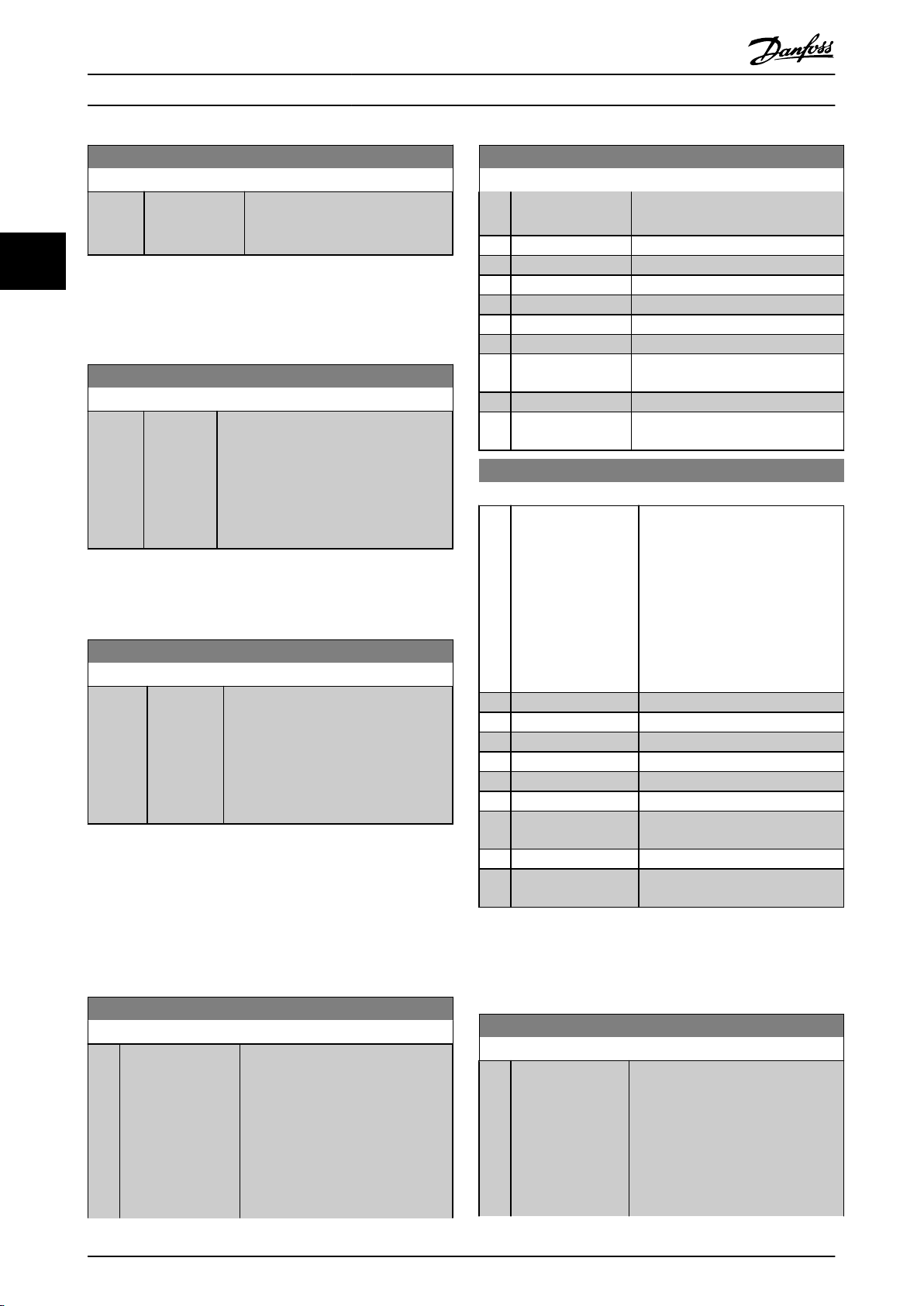
Parameter Descriptions
VLT® AutomationDrive Programming Guide
4-17 Torque Limit Generator Mode
Range: Function:
100.0 %* [0.0 - 1000.0 %] This function limits the torque on
shaft to protect the mechanical
the
installation.
33
NOTE
The
torque limit reacts on the actual, non-filtrated torque,
including torque spikes. This is not the torque that is seen
from the or the as that is filtered.
4-18 Current Limit
Range: Function:
160.0%* [1.0 -
1000.0
This is a true current limit function that
%]
continues in the oversynchronous range,
however due to field weakening the
motor torque at current limit will drop
accordingly when the voltage increase
stops above the synchronised speed of
the motor.
NOTE
[20] is selected in 1-90 Motor Thermal Protection,
If
4-18 Current Limit current limit must be set to 150%.
4-19 Max Output Frequency
Range: Function:
132.0
Hz*
[1.0 -
1000.0
Provides a final limit on the output
Hz]
frequency for improved safety in
applications where you want to avoid
accidental over-speeding. This limit is
final in all configurations (independent
of the setting in 1-00 Configuration
Mode).
NOTE
This parameter cannot be adjusted while the motor is
running.
4-20 Torque Limit Factor Source
Option: Function:
is in Speed
Loop.
[0] * No function
[2] Analog in 53
[4] Analog in 53 inv
[6] Analog in 54
[8] Analog in 54 inv
[10] Analog in X30-11
[12] Analog in X30-11
inv
[14] Analog in X30-12
[16] Analog in X30-12
inv
Open Loop or Speed Closed
4-21 Speed Limit Factor SourceOption
Option: Function:
Select an analog input for scaling
settings in 4-19 Max Output
the
Frequency from 0% to 100% (or vice
versa). The signal levels
corresponding to 0% and 100% are
defined in the analog input scaling,
e.g. parameter group 6-1*. This
parameter is only active when
1-00 Configuration Mode is in Torque
Mode.
[0] * No function
[2] Analog input 53
[4] Analog input 53 inv
[6] Analog input 54
[8] Analog input 54 inv
[10] Analog input X30-11
[12] Analog input X30-11
inv
[14] Analog input X30-12
[16] Analog input X30-12
inv
NOTE
output frequency cannot exceed 10% of the inverter
Max.
switching frequency (14-01 Switching Frequency).
4-20 Torque Limit Factor Source
Option: Function:
Select an analog input for scaling the
in 4-16 Torque Limit Motor
settings
Mode and 4-17 Torque Limit Generator
Mode from 0% to 100% (or inverse).
The signal levels corresponding to
0% and 100% are defined in the
analog input scaling, e.g. parameter
group 6-1*. This parameter is only
active when 1-00 Configuration Mode
68 MG33MF02 - VLT® is a registered Danfoss trademark
3.6.2 4-3* Motor Feedback Monitoring
The parameter group includes monitoring and handling of
motor
feedback devices as encoders, resolvers etc.
4-30 Motor Feedback Loss Function
Option: Function:
This function is used to monitor for
consistency
the feedback signal is available.
Select which reaction the frequency
converter should take if a feedback
fault is detected. The selected action
is to take place when the feedback
signal differs from the output speed
in feedback signal, i.e. if
Page 70
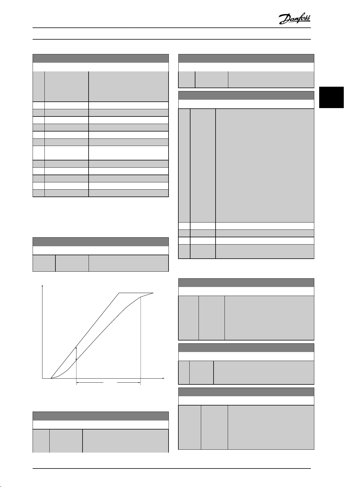
Time
[sec]
Speed
[rpm]
n
calc
n
actual
P 4-32
130BA221.10
P 4-31
Parameter Descriptions
VLT® AutomationDrive Programming Guide
4-30 Motor Feedback Loss Function
Option: Function:
by the value set in 4-31
Feedback Speed Error for longer than
the value set in4-32 Motor Feedback
Loss Timeout.
[0] Disabled
[1] Warning
[2] * Trip
[3] Jog
[4] Freeze Output
[5] Max Speed
[6] Switch to Open
Loop
[7] Select Setup 1
[8] Select Setup 2
[9] Select Setup 3
[10] Select Setup 4
[11] stop & trip
Warning 90 is active as soon as the value in 4-31
Motor
Motor
Feedback Speed Error is exceeded, regardless of the setting
of 4-32 Motor Feedback Loss Timeout. Warning/Alarm 61
Feedback Error is related to the Motor Feedback Loss
Function.
4-31 Motor Feedback Speed Error
Range: Function:
300 RPM* [1 - 600 RPM] Select the max allowed error in speed
speed vs. feedback).
(output
4-32 Motor Feedback Loss Timeout
Range: Function:
enabling the function selected in
Motor Feedback Loss Function.
4-30
4-34 Tracking Error Function
Option: Function:
This function is used to monitor that the
application
In Closed loop the speed reference to the PID
is compared to the encoder feedback (filtered)
In open loop the speed reference to the PID is
compensated for slip and compared to the
frequency that is sent to the motor
(16-13 Frequency).
The reaction will be activated if the measured
difference is more than specified in
4-35 Tracking Error for the time specified in
4-36 Tracking Error Timeout.
A tracking error in closed loop does not imply
that there is a problem with the feedback
signal! A tracking error can be the result of
torque limit at too big loads.
[0] * Disable
[1] Warning
[2] Trip
[3] Trip after
stop
follows the expected speed profile.
Warning/Alarm 78 Tracking Error is related to the Tracking
Error Function.
3 3
Illustration 3.31
4-32 Motor Feedback Loss Timeout
Range: Function:
0.05 s* [0.00 - 60.00s]Set the timeout value allowing the
speed error set in 4-31 Motor Feedback
Speed Error to be exceeded before
4-35 Tracking Error
Range: Function:
10 RPM* [1 - 600
RPM]
Enter the maximum permissible speed
between the motor speed and the
error
output of the ramp when not ramping. In
open loop the motor speed is estimated
and in closed loop it is the feedback from
encoder/resolver.
4-36 Tracking Error Timeout
Range: Function:
1 s* [0 - 60 s] Enter the time-out period during which an error
than the value set in 4-35 Tracking Error
greater
is permissible.
4-37 Tracking Error Ramping
Range: Function:
100 RPM* [1 - 600
RPM]
Enter the maximum permissible speed
error
between the motor speed and the
output of the ramp when ramping. In
open loop the motor speed is estimated
and in closed loop it is the feedback
from encoder/resolver.
MG33MF02 - VLT® is a registered Danfoss trademark
69
Page 71

130BA064.10
(P 4-18)
(P 4-51)
(P 4-50)
(P 4-11) (P 4-53)(P 4-52) (P 4-13)
I
HIGH
I
LOW
n
LOW
n
HIGH
n
motor
I
motor
REF
ON REF
IN RANGE
I
LIM
n
MAX
n
MIN
[RPM]
Parameter Descriptions
VLT® AutomationDrive Programming Guide
4-38 Tracking Error Ramping Timeout
Range: Function:
1 s* [0 - 60 s] Enter the time-out period during which an error
than the value set in 4-37 Tracking Error
greater
Ramping while Ramping is permissible.
33
4-39 Tracking Error After Ramping Timeout
Range: Function:
5 s* [0 - 60 s]
Enter the time-out period after ramping where
4-37
Tracking Error Ramping and 4-38 Tracking
Error Ramping Timeout are still active.
4-51 Warning Current High
Range: Function:
signal on terminal 27 or 29 (FC 302 only)
on relay output 01 or 02 (FC 302
and
only). Refer to Illustration 3.32.
4-52 Warning Speed Low
Range: Function:
0 RPM* [0 - par.
4-53
Enter the n
RPM]
speed exceeds this limit, the display reads
Speed Low. The signal outputs can be
value. When the motor
LOW
programmed to produce a status signal on
terminal 27 or 29 (FC 302 only) and on
3.6.3 4-5* Adjustable Warnings
Use these parameters to adjust warning limits for current,
reference and feedback.
speed,
Warnings are shown on the LCP, and can be programmed
to be outputs or to be read out via serial bus in the
Extended Status Word.
4-53 Warning Speed High
Range: Function:
par.
4-13
RPM*
[par.
4-52
par. 4-13
RPM]
relay output 01 or 02 (FC 302 only).
Enter the n
-
speed exceeds this limit, the display reads
value. When the motor
HIGH
Speed High. The signal outputs can be
programmed to produce a status signal on
terminal 27 or 29 and on relay output 01 or
02. Programme the upper signal limit of the
motor speed, n
, within the normal
HIGH
working range of the frequency converter.
Refer to Illustration 3.32.
Illustration 3.32 Adjustable Warnings
4-50 Warning Current Low
Range: Function:
0.00 A* [0.00 par.
A]
4-51 Warning Current High
Enter the I
4-51
current falls below this limit, the display
LOW
reads Current Low. The signal outputs can be
programmed to produce a status signal on
terminal 27 or 29 (FC 302 only) and on relay
output 01 or 02 (FC 302 only). Refer to
Illustration 3.32.
Range: Function:
par.
16-37
A*
[par. 4-50
- par.
16-37 A]
Enter the I
current exceeds this limit, the display
reads Current High. The signal outputs can
be programmed to produce a status
value. When the motor
value. When the motor
HIGH
4-54 Warning Reference Low
Range: Function:
-999999.999
N/A*
[-999999.999 par.
4-55 N/A]
Enter the lower reference limit.
When the actual reference falls
below this limit, the display
indicates Ref
outputs can be programmed
to produce a status signal on
terminal 27 or 29 (FC 302 only)
and on relay output 01 or 02
(FC 302 only).
4-55 Warning Reference High
Range: Function:
999999.999
N/A*
[par. 4-54 -
999999.999
N/A]
Enter the upper reference limit.
the actual reference
When
exceeds this limit, the display
reads Ref High. The signal
outputs can be programmed to
produce a status signal on
terminal 27 or 29 (FC 302 only)
and on relay output 01 or 02 (FC
302 only).
. The signal
LOW
70 MG33MF02 - VLT® is a registered Danfoss trademark
Page 72

Parameter Descriptions
VLT® AutomationDrive Programming Guide
4-56 Warning Feedback Low
Range: Function:
-999999.999
ReferenceFeedbackUnit*
[-999999.999 -
4-57
par.
ReferenceFeedbackUnit]
Enter the lower feedback
limit. When the feedback
falls below this limit, the
display reads Feedb Low.
The signal outputs can
be programmed to
produce a status signal
on terminal 27 or 29 (FC
302 only) and on relay
output 01 or 02 (FC 302
only).
4-57 Warning Feedback High
Range: Function:
999999.999
ReferenceFeedbackUnit*
[par. 4-56 -
999999.999
ReferenceFeedbackUnit]
Enter the upper
feedback
feedback exceeds this
limit, the display reads
Feedb High. The signal
outputs can be
programmed to produce
a status signal on
terminal 27 or 29 (FC
302 only) and on relay
output 01 or 02 (FC 302
only).
limit. When the
4-58 Missing Motor Phase Function
Displays alarm 30, 31 or 32 in the event of a missing motor
It is strongly recommended to enable to avoid motor
phase.
damage.
Option: Function:
[0] * Disabled The frequency converter does not issue a
motor phase alarm. Not
missing
recommended due to risk of motor damage.
[1] Trip 100 ms For a quick detection time and alarm in the
of a missing motor phase.
event
[2] Trip 1000 ms For a slow detection time and alarm in the
of a missing motor phase.
event
4-60 Bypass Speed From [RPM]
Array [4]
Range: Function:
0 RPM* [0 - par. 4-13
RPM]
Some systems call for avoiding certain
speeds due to resonance
output
problems in the system. Enter the
lower limits of the speeds to be
avoided.
4-61 Bypass Speed From [Hz]
Array [4]
Range: Function:
- par.
Size related* [ 0.0
4-14 Hz]
Some systems call for avoiding
certain output speeds due to
resonance problems in the system.
Enter the lower limits of the speeds
to be avoided.
4-62 Bypass Speed To [RPM]
Array [4]
Range: Function:
0 RPM* [0 - par. 4-13
RPM]
Some systems call for avoiding certain
speeds due to resonance
output
problems in the system. Enter the
upper limits of the speeds to be
avoided.
4-63 Bypass Speed To [Hz]
Array [4]
Range: Function:
0 Hz* [0.0 - par. 4-14
Hz]
Some systems call for avoiding certain
speeds due to resonance
output
problems in the system. Enter the upper
limits of the speeds to be avoided.
3 3
NOTE
This
parameter cannot be adjusted while the motor is
running.
3.6.4 4-6* Speed Bypass
Some systems call for avoiding certain output frequencies
or
speeds, due to resonance problems in the system. A
maximum of four frequency or speed ranges can be
avoided.
MG33MF02 - VLT® is a registered Danfoss trademark
71
Page 73

Parameter Descriptions
VLT® AutomationDrive Programming Guide
3.7 Parameters: 5-** Digital In/Out
3.7.1 5-0* Digital I/O Mode
Parameters for configuring the input and output using
and PNP.
NPN
33
5-00 Digital I/O Mode
Option: Function:
Digital inputs and programmed digital outputs are
for operation either in PNP or NPN
PNP systems
NPN
[0] * PNP
[1] NPN
pre-programmable
systems.
Action on positive directional pulses (↕).
are pulled down to GND.
Action on negative directional pulses (↕).
systems are pulled up to + 24 V, internally in the
frequency converter.
NOTE
Once
this parameter has been changed, it must be
activated by performing a power cycle.
5-01 Terminal 27 Mode
Option: Function:
[0] * Input Defines terminal 27 as a digital input.
[1] Output Defines terminal 27 as a digital output.
NOTE
parameter cannot be adjusted while the motor is
This
running.
5-02 Terminal 29 Mode
Option: Function:
[0] * Input Defines terminal 29 as a digital input.
[1] Output Defines terminal 29 as a digital output.
This parameter is available for FC 302 only.
3.7.2 Digital Inputs
The digital inputs are used for selecting various functions
in the frequency converter. All digital inputs can be set to
the following functions:
Digital input function Select Terminal
No operation [0] All *term 32, 33
Reset [1] All
Coast inverse [2] All *term 27
Coast and reset inverse [3] All
Quick stop inverse [4] All
DC-brake inverse [5] All
Stop inverse [6] All
Start [8] All *term 18
Digital input function Select Terminal
Latched start [9] All
Reversing [10] All *term 19
Start reversing [11] All
Enable start forward [12] All
Enable start reverse [13] All
Jog [14] All *term 29
Preset reference on [15] All
Preset ref bit 0 [16] All
Preset ref bit 1 [17] All
Preset ref bit 2 [18] All
Freeze reference [19] All
Freeze output [20] All
Speed up [21] All
Speed down [22] All
Set-up select bit 0 [23] All
Set-up select bit 1 [24] All
Precise stop inverse [26] 18, 19
Precises start, stop [27] 18, 19
Catch up [28] All
Slow down [29] All
Counter input [30] 29, 33
Pulse input Edge Trigged [31] 29, 33
Pulse input Time Based [32] 29, 33
Ramp bit 0 [34] All
Ramp bit 1 [35] All
Latched precise start [40] 18, 19
Latched precise stop
inverse
External interlock [51]
DigiPot Increase [55] All
DigiPot Decrease [56] All
DigiPot Clear [57] All
Digipot Hoist [58] All
Counter A (up) [60] 29, 33
Counter A (down) [61] 29, 33
Reset Counter A [62] All
Counter B (up) [63] 29, 33
Counter B (down) [64] 29, 33
Reset Counter B [65] All
Mech. Brake Feedb. [70] All
Mech. Brake Feedb. Inv. [71] All
PID Error Inv. [72] All
PID Reset I-part [73] All
PID enable [74] All
MCO Specific [75]
PTC Card 1 [80] All
Profidrive OFF2 [91]
Profidrive OFF3 [92]
Start edge triggered [98]
Safe Option Reset [100]
Table 3.11 Digital Input Function
[41] 18, 19
72 MG33MF02 - VLT® is a registered Danfoss trademark
Page 74

Parameter Descriptions
VLT® AutomationDrive Programming Guide
FC 300 standard terminals are 18, 19, 27, 29, 32 and 33.
101 terminals are X30/2, X30/3 and X30/4.
MCB
Terminal 29 functions as an output only in FC 302.
Functions dedicated to only one digital input are stated in
the associated parameter.
All digital inputs can be programmed to these functions:
[0] No
operation
[1] Reset Resets frequency converter after a TRIP/
[2] Coast
inverse
[3] Coast and
reset inverse
[4] Quick stop
inverse
[5] DC-brake
inverse
[6] Stop inverse Stop Inverted function. Generates a stop
No reaction to signals transmitted to the
terminal.
ALARM. Not all alarms can be reset.
(Default Digital input 27): Coasting stop,
input (NC). The frequency converter
inverted
leaves the motor in free mode. Logic ‘0’
⇒coasting stop.
Reset and coasting stop Inverted input (NC).
Leaves motor in free mode and resets
frequency converter. Logic ‘0’ ⇒ coasting stop
and reset.
Inverted input (NC). Generates a stop in
accordance
3-81 Quick Stop Ramp Time. When motor
stops, the shaft is in free mode. Logic ‘0’ ⇒
Quick-stop.
Inverted input for DC braking (NC). Stops
motor
a certain time period. See 2-01 DC Brake
Current to 2-03 DC Brake Cut In Speed [RPM].
The function is only active when the value in
2-02 DC Braking Time is different from 0.
Logic ’0’ => DC braking.
function
from logical level ‘1’ to ‘0’. The stop is
performed according to the selected ramp
time (3-42 Ramp 1 Ramp Down Time,
3-52 Ramp 2 Ramp down Time, 3-62 Ramp 3
Ramp down Time, 3-72 Ramp 4 Ramp Down
Time).
with quick-stop ramp time set in
by energizing it with a DC current for
when the selected terminal goes
NOTE
When the frequency converter is at the
torque limit and has received a stop
command, it may not stop by itself. To
ensure that the frequency converter
stops, configure a digital output to
Torque limit & stop [27] and connect this
digital output to a digital input that is
configured as coast.
[8] Start (Default Digital input 18): Select start for a
[9] Latched
start
start/stop
= stop.
The motor starts, if a pulse is applied for min.
2ms.
activated or a reset command (via DI) is
given.
command. Logic ‘1’ = start, logic ‘0’
The motor stops when Stop inverse is
[10] Reversing (Default Digital input 19). Change the
direction
‘1’ to reverse. The reversing signal only
changes the direction of rotation. It does not
activate the start function. Select both
directions in 4-10 Motor Speed Direction. The
function is not active in process closed loop.
[11] Start
reversing
[12] Enable start
forward
[13] Enable start
reverse
[14] Jog (Default Digital input 29): Use to activate jog
[15] Preset
reference
[16] Preset ref
0
bit
[17] Preset ref
1
bit
[18] Preset ref
2
bit
Preset ref. bit 2 1 0
Preset ref. 0 0 0 0
Preset ref. 1 0 0 1
Preset ref. 2 0 1 0
Preset ref. 3 0 1 1
Preset ref. 4 1 0 0
Preset ref. 5 1 0 1
Preset ref. 6 1 1 0
Preset ref. 7 1 1 1
Table 3.12 Preset Ref. Bit
[19] Freeze
ref
[20] Freeze
output
Used for start/stop and for reversing on the
same
the same time.
Disengages the counterclockwise movement
and
Disengages the clockwise movement and
allows
speed.
Shifts between external reference and preset
on
reference. It is assumed that [1] External/preset
has been selected in 3-04 Reference Function.
Logic '0' = external reference active; logic '1'
= one of the eight preset references is active.
Preset ref. bit 0,1, and 2 enables a choice
between one of the eight preset references
according to Table 3.12.
Same as Preset ref bit 0 [16].
Same as Preset ref bit 0 [16].
Freezes the actual reference, which is now the
point of enable/condition for Speed up and Speed
down to be used. If Speed up/down is used, the
speed change always follows ramp 2 (3-51 Ramp 2
Ramp up Time and 3-52 Ramp 2 Ramp down Time)
in the range 0 - 3-03 Maximum Reference.
Freezes the actual motor frequency (Hz), which is
the point of enable/condition for Speed up
now
and Speed down to be used. If Speed up/down is
used, the speed change always follows ramp 2
(3-51 Ramp 2 Ramp up Time and 3-52 Ramp 2
Ramp down Time) in the range 0 - 1-23 Motor
Frequency.
of motor shaft rotation. Select Logic
wire. Signals on start are not allowed at
allows for the clockwise direction.
for the counterclockwise direction.
See 3-11 Jog Speed [Hz].
3 3
MG33MF02 - VLT® is a registered Danfoss trademark
73
Page 75

Pulse
Sample time
130BB463.10
Parameter Descriptions
VLT® AutomationDrive Programming Guide
NOTE
Freeze output is active, the frequency
When
[27] Precise
start,
converter cannot be stopped via a low ‘start
[8]’ signal. Stop the frequency converter via a
terminal programmed for Coasting inverse [2]
or Coast and reset, inverse.
33
[21] SpeedupSelect Speed up and Speed down if digital control
of the up/down speed is desired (motor potentiometer). Activate this function by selecting either
Freeze reference or Freeze output. When Speed
up/down is activated for less than 400 msec. the
resulting reference will be increased/ decreased by
0.1 %. If Speed up/down is activated for more than
400 msec. the resulting reference will follow the
setting in ramping up/ down parameter 3-x1/ 3-x2.
Shut down Catch up
Unchanged speed 0 0
Reduced by %-value 1 0
Increased by %-value 0 1
Reduced by %-value 1 1
Table 3.13
[22] Speed
down
[23] Set-up
select
0
[24] Set-up
select
1
[26] Precise
inv.
stop
Same as [21]
Select Set-up select bit 0 or Select Set-up select
bit
bit 1 to select one of the four set-ups. Set
0-10 Active Set-up to Multi Set-up.
(Default Digital input 32): Same as [23] Set-up
bit
select bit 0.
Sends an inverted stop signal when the precise
stop function is activated in 1-83 Precise Stop
Function.
Precise stop inverse function is available for
terminals 18 or 19.
Speed up.
[28] Catch up Increases reference value by percentage
[29] Slow
down
[30] Counter
input
[31] Pulse
edge
triggered
Use when Precise ramp stop [0] is selected in
stop
1-83 Precise Stop Function.
Precise start, stop is available for terminals 18
and 19.
Precise start makes sure that the angle that the
rotor turns from standing still to reference is the
same for each start (for same ramp time, same
set-point). This is the equivalent to the precise
stop where the angle that the rotor turns from
reference to standing still is the same for each
stop.
When using for 1-83 Precise Stop Function [1] or
[2]:
The frequency converter needs a Precise Stop
signal before the value of 1-84 Precise Stop
Counter Value is reached. If this is not supplied,
the frequency converter will not stop when the
value in 1-84 Precise Stop Counter Value is
reached.
Precise start, stop must be triggered by a Digital
Input and is available for terminals 18 and 19.
set in 3-12 Catch up/slow Down Value.
(relative)
Reduces reference value by percentage (relative)
in 3-12 Catch up/slow Down Value.
set
Precise stop function in 1-83
Function acts as Counter stop or speed
compensated counter stop with or without
reset. The counter value must be set in
1-84 Precise Stop Counter Value.
Counts the number of pulse flanks per sample
This gives a higher resolution at high
time.
frequencies, but is not as precise at lower
frequencies. Use this pulse principle for
encoders with very low resolution (e.g. 30 ppr).
Precise Stop
Illustration 3.33
[32] Pulse time
based
74 MG33MF02 - VLT® is a registered Danfoss trademark
Measures the duration between pulse flanks.
This
frequencies, but is not as precise at higher
frequencies. This principle has a cut-off
frequency which makes it unsuited for encoders
with very low resolutions (e.g. 30 ppr) at low
speeds.
gives a higher resolution at lower
Page 76
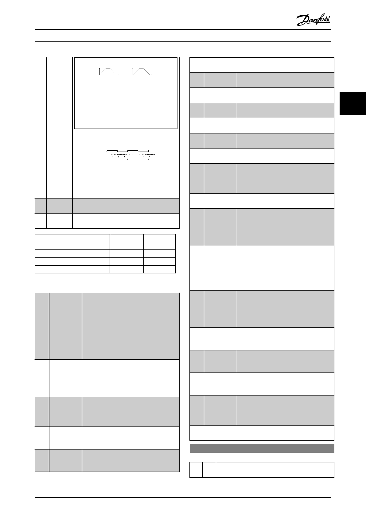
Speed [rpm] Speed [rpm]
Time[sec] Time[sec]a b
130BB462.10
Read Timer:
20 timer tides
Read Timer:
20 timer tides
Time Start
Time counter
Sample time
Timer
Pulse
130BB464.10
Parameter Descriptions
a: very low encoder
resolution
VLT® AutomationDrive Programming Guide
b: standard encoder
resolution
Table 3.14
Illustration 3.34
[34] Ramp bit0Enables a choice between one of the 4 ramps
available,
according to the table below.
[35] Ramp bit1Same as Ramp bit 0.
Preset ramp bit 1 0
Ramp 1 0 0
Ramp 2 0 1
Ramp 3 1 0
Ramp 4 1 1
Table 3.15 Preset Ramp Bit
[40] Latched
Precise
A latched Precise Start only requires a pulse
Start
of 3ms on T18 or T19.
When using for 1-83 [1] or [2]:
When the reference is reached, the
frequency converter will internally enable
the Precise Stop signal. This means that the
frequency converter will do the Precise
Stop when the counter value of 1-84 Precise
Stop Counter Value is reached.
[41] Latched
Precise
inverse
Sends a latched stop signal when the
Stop
precise stop function is activated in
1-83 Precise Stop Function. The Latched
Precise stop inverse function is available for
terminals 18 or 19.
[51] External
interlock
This function makes it possible to give an
fault to the drive. This fault is
external
treated in the same way as an internally
generated alarm.
[55] DigiPot
Increase
INCREASE signal to the Digital Potenti-
function described in parameter
ometer
group 3-9*
[56] DigiPot
Decrease
DECREASE signal to the Digital Potenti-
function described in parameter
ometer
group 3-9*
[57] DigiPot Clear Clears the Digital Potentiometer reference
described
in parameter group 3-9*
[60] Counter A (Terminal 29 or 33 only) Input for
increment
counting in the SLC counter.
[61] Counter A (Terminal 29 or 33 only) Input for
counting in the SLC counter.
[62] Reset
Counter
decrement
Input for reset of counter A.
A
[63] Counter B (Terminal 29 or 33 only) Input for
increment
counting in the SLC counter.
[64] Counter B (Terminal 29 or 33 only) Input for
counting in the SLC counter.
1-01 Motor Control Principle to [3] flux w/
[65] Reset
B
Counter
[70] Mech. Brake
Feedback
decrement
Input for reset of counter B.
Brake feedback for hoisting applications:
Set
motor feedback; set 1-72 Start Function to
[6] Hoist mech brake Ref.
[71] Mech. Brake
Feedback
[72] PID error
inverse
Inverted brake feedback for hoisting
inv.
applications
When enabled, it inverts the resulting error
the process PID controller. Available
from
only if "Configuration Mode" is set to
"Surface Winder", "Extended PID Speed OL"
or "Extended PID Speed CL".
[73] PID reset I-
part
When enabled, resets the I-part of the
PID controller. Equivalent to
Process
7-40 Process PID I-part Reset. Available only
if "Configuration Mode" is set to "Surface
Winder", "Extended PID Speed OL" or
"Extended PID Speed CL".
[74] PID enable When enabled, enables the extended
PID controller. Equivalent to
process
7-50 Process PID Extended PID. Available only
if "Configuration Mode" is set "Extended
PID Speed OL" or "Extended PID Speed CL".
[80] PTC Card 1 All Digital Inputs can be set to PTC Card 1
However, only one Digital Input must
[80].
be set to this choice.
[91] Profidrive
OFF2
The functionality is the same as the
according
control word bit of the Profibus/
Profinet option.
[92] Profidrive
OFF3
The functionality is the same as the
according
control word bit of the Profibus/
Profinet option.
[98] Start edge
triggered
Edge triggered start command. Keeps the
command alive, even if the input is
start
going back to low - can be used for a start
push-button.
[100] Safe Option
Reset
5-10 Terminal 18 Digital Input
Option: Function:
[8] * Start
Functions are described under parameter group 5-1*
Digital
Inputs
3 3
MG33MF02 - VLT® is a registered Danfoss trademark
75
Page 77

Parameter Descriptions
VLT® AutomationDrive Programming Guide
5-11 Terminal 19 Digital Input
Option: Function:
[10] * Reversing Functions are described under parameter group
Digital Inputs
5-1*
5-12 Terminal 27 Digital Input
33
Option: Function:
[2] * Coast inverse Functions are described under parameter
group
5-1* Digital Inputs
5-13 Terminal 29 Digital Input
Option: Function:
Select the function from the available digital input
and the additional options [60], [61], [63] and
range
[64]. Counters are used in Smart Logic Control
functions.This parameter is available for FC 302 only.
[14] * Jog Functions are described under parameter group 5-1*
Inputs
Digital
5-14 Terminal 32 Digital Input
Option: Function:
Select the function from the available digital
range.
input
[0] * No operation
Functions are described under 5-1*
Inputs
Digital
5-15 Terminal 33 Digital Input
Option: Function:
Select the function from the available digital
range and the additional options [60],
input
[61], [63] and [64]. Counters are used in
Smart Logic Control functions.
[0] * No operation
Functions are described under 5-1*
Inputs
Digital
5-16 Terminal X30/2 Digital Input
Option: Function:
[0] * No operation This parameter is active when option module
is installed in the frequency
MCB101
converter. Functions are described under
5-1* Digital Inputs
5-17 Terminal X30/3 Digital Input
Option: Function:
[0] * No operation This parameter is active when option module
is installed in the frequency
MCB101
converter. Functions are described under
5-1* Digital Inputs
5-18 Terminal X30/4 Digital Input
Option: Function:
[0] * No operation This parameter is active when option module
is installed in the frequency
MCB101
converter. Functions are described under
5-1* Digital Inputs
5-19 Terminal 37 Safe Stop
Option: Function:
[1]*Safe Stop
Alarm
[3] Safe Stop
Warning
[4] PTC 1 Alarm Coasts frequency converter when safe stop is
[5] PTC 1
Warning
[6] PTC 1 &
A
Relay
[7] PTC 1 &
W
Relay
[8] PTC 1 &
A/W
Relay
[9] PTC 1 &
W/A
Relay
Coasts frequency converter when safe stop is
activated.
input or fieldbus.
Coasts frequency converter when safe stop is
activated
reestablished, the frequency converter will
continue without manual reset.
activated.
input or fieldbus. Choice 4 is only available
when the MCB 112 PTC Thermistor Card is
connected.
Coasts frequency converter when safe stop is
activated
reestablished, the frequency converter will
continue without manual reset, unless a
Digital Input set to PTC Card 1 [80] is still
enabled. Choice 5 is only available when the
MCB 112 PTC Thermistor Card is connected.
This choice is used when the PTC option is
gated together with a Stop button through a
Safety relay to T-37. Coasts frequency
converter when safe stop is activated. Manual
reset from LCP, digital input or fieldbus.
Choice 6 is only available when the MCB 112
PTC Thermistor Card is connected.
This choice is used when the PTC option is
gated together with a Stop button through a
Safety relay to T-37. Coasts frequency
converter when safe stop is activated (T-37
off). When safe stop circuit is reestablished,
the frequency converter will continue without
manual reset, unless a Digital Input set to
PTC Card 1 [80] is (still) enabled. Choice 7 is
only available when the MCB 112 PTC
Thermistor Card is connected.
This choice makes it possible to use a
combination of Alarm and Warning. Choice 8
is only available when the MCB 112 PTC
Thermistor Card is connected.
This choice makes it possible to use a
combination of Alarm and Warning. Choice 9
is only available when the MCB 112 PTC
Thermistor Card is connected.
Manual reset from LCP, digital
(T-37 off). When safe stop circuit is
Manual reset from LCP, digital
(T-37 off). When safe stop circuit is
Choises 4 - 9 are only available when the MCB 112 PTC
Thermistor
Card is connected.
76 MG33MF02 - VLT® is a registered Danfoss trademark
Page 78
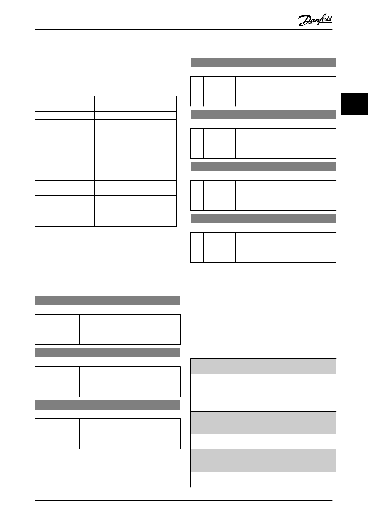
Parameter Descriptions
VLT® AutomationDrive Programming Guide
NOTE
Auto Reset/Warning is selected the frequency
When
converter opens up for automatic restart.
Function No. PTC Relay
No Function [0] - Safe Stop Alarm [1]* - Safe Stop [A68]
Safe Stop Warning [3] - Safe Stop [W68]
PTC 1 Alarm [4] PTC 1 Safe Stop
[A71]
PTC 1 Warning [5] PTC 1 Safe Stop
[W71]
PTC 1 & Relay A [6] PTC 1 Safe Stop
[A71]
PTC 1 & Relay W [7] PTC 1 Safe Stop
[W71]
PTC 1 & Relay A/W [8] PTC 1 Safe Stop
[A71]
PTC 1 & Relay W/A [9] PTC 1 Safe Stop
[W71]
Table 3.16 Overview of Functions, Alarms and Warnings
W means warning and A means alarm. For further information, see
Alarms and Warnings in section Troubleshooting in the Design Guide
or the Operating Instructions
-
-
Safe Stop [A68]
Safe Stop [W68]
Safe Stop [W68]
Safe Stop [A68]
5-23 Terminal X46/7 Digital Input
Option: Function:
[0] * No operation This parameter is active when option
moduleMCB
converter. Functions are described under
parameter group 5-1* Digital Inputs
113 is installed in the frequency
5-24 Terminal X46/9 Digital Input
Option: Function:
[0] * No operation This parameter is active when option module
MCB
113 is installed in the frequency
converter. Functions are described under
parameter group 5-1* Digital Inputs
5-25 Terminal X46/11 Digital Input
Option: Function:
[0] * No operation This parameter is active when option
moduleMCB
converter. Functions are described under
parameter group 5-1* Digital Inputs
113 is installed in the frequency
5-26 Terminal X46/13 Digital Input
Option: Function:
[0] * No operation This parameter is active when option module
113 is installed in the frequency
MCB
converter. Functions are described under
parameter group 5-1* Digital Inputs
3 3
A dangerous failure related to Safe Stop will give Alarm:
Dangerous Failure [A72].
Refer to in Table 5.3.
5-20 Terminal X46/1 Digital Input
Option: Function:
[0] * No operation This parameter is active when option module
MCB 113 is installed in the frequency
converter. Functions are described under
parameter group 5-1* Digital Inputs
5-21 Terminal X46/3 Digital Input
Option: Function:
[0] * No operation This parameter is active when option
moduleMCB
converter. Functions are described under
parameter group 5-1* Digital Inputs
113 is installed in the frequency
5-22 Terminal X46/5 Digital Input
Option: Function:
[0] * No operation This parameter is active when option
moduleMCB
converter. Functions are described under
parameter group 5-1* Digital Inputs
113 is installed in the frequency
3.7.3 5-3* Digital Outputs
The 2 solid-state digital outputs are common for terminals
27 and 29. Set the I/O function for terminal 27 in
5-01 Terminal 27 Mode, and set the I/O function for
terminal 29 in 5-02 Terminal 29 Mode.
NOTE
These
parameters cannot be adjusted while the motor is
running.
[0] No operation
[1] Control ready The control card is ready. E.g.: Feedback
[2] Drive ready The frequency converter is ready for
[3] Drive ready /
control
remote
[4] Enable / no
warning
[5] VLT running Motor is running and shaft torque
Default for all digital outputs and relay
outputs
a frequency converter where the
from
control is supplied by an external 24 V
(MCB 107) and the main power to the
unit is not detected.
operation
the control board.
The frequency converter is ready for
operation and is in [Auto On] mode.
Ready for operation. No start or stop
command
No warnings are active.
present.
and applies a supply signal on
is been given (start/disable).
MG33MF02 - VLT® is a registered Danfoss trademark
77
Page 79

Parameter Descriptions
VLT® AutomationDrive Programming Guide
[6] Running / no
warning
[7] Run in range /
warning
no
33
[8] Run on
reference
warning
[9] Alarm An alarm activates the output. There are
[10] Alarm or
warning
[11] At torque limit
[12] Out of current
range
[13] Below current,
low
[14] Above current,
high
[15] Out of range Output frequency is outside the
[16] Below speed,
low
[17] Above speed,
high
[18] Out of
feedback
[19] Below feedback
low
[20] Above feedback
high
[21] Thermal
warning
[22] Ready, no
thermal
warning
[23] Remote, ready,
no
warning
[24] Ready, no
over-/
voltage
[25] Reverse The motor runs (or is ready to run)
range
thermal
under
Output speed is higher than the speed
in 1-81 Min Speed for Function at Stop
set
[RPM]. The motor is running and there
are no warnings.
Motor is running within the programmed
current and speed ranges set in
4-50 Warning Current Low to 4-53 Warning
Speed High. There are no warnings.
Motor runs at reference speed. No
/ no
warnings.
warnings.
no
An alarm or a warning activates the
output.
The torque limit set in 4-16
Motor Mode or 4-17 Torque Limit
Generator Mode has been exceeded.
The motor current is outside the range
in 4-18 Current Limit.
set
Motor current is lower than set in
Warning Current Low.
4-50
Motor current is higher than set in
Warning Current High.
4-51
frequency
Speed Low and 4-53 Warning Speed High.
Output speed is lower than the setting in
4-52
Output speed is higher than the setting
in
Feedback is outside the range set in
4-56 Warning Feedback Low and
4-57 Warning Feedback High.
Feedback is below the limit set in
4-56
Feedback is above the limit set in
4-57
The thermal warning turns on when the
temperature
motor, the frequency converter, the
brake resistor, or the thermistor.
Frequency converter is ready for
operation
temperature warning.
Frequency converter is ready for
operation and is in [Auto On] mode.
There is no over-temperature warning.
Frequency converter is ready for
operation and the mains voltage is within
the specified voltage range (see General
Specifications section in the Design
Guide).
clockwise
clockwise when logic=1. The output
range set in 4-52 Warning
Warning Speed Low.
4-53 Warning Speed High.
Warning Feedback Low.
Warning Feedback High.
exceeds the limit in the
and there is no over-
when logic=0 and counter
Torque Limit
[26] Bus OK Active communication (no time-out) via
[27] Torque limit
stop
and
[28] Brake, no brake
warning
[29] Brake ready, no
fault
[30] Brake fault
(IGBT)
[31] Relay 123 Relay is activated when Control Word [0]
[32] Mechanical
control
brake
[33] Safe stop
activated
302 only)
[40] Out of ref
range
[41] Below reference
low
[42] Above
reference
[43] Extended PID
Limit
[45] Bus Ctrl Controls output via bus. The state of the
[46] Bus Ctrl On at
timeout
[47] Bus Ctrl Off at
timeout
[51] MCO controlled Active when a MCO 302 or MCO 305 is
[55] Pulse output
[60] Comparator 0 See parameter group 13-1*. If
(FC
high
changes as soon as the reversing signal is
applied.
serial communication port.
the
Use in performing a coasting stop and in
torque limit condition. If the frequency
converter has received a stop signal and
is at the torque limit, the signal is Logic
‘0’.
Brake is active and there are no
warnings.
Brake is ready for operation and there
no faults.
are
Output is Logic ‘1’ when the brake IGBT
short-circuited. Use this function to
is
protect the frequency converter if there
is a fault on the brake modules. Use the
output/relay to cut out the main voltage
from the frequency converter.
selected in parameter group 8-**.
is
Enables control of an external mechanical
brake, see description in the section
Control of Mechanical Brake, and
parameter group 2-2*
Indicates that the safe stop on terminal
37 has been activated.
Active when the actual speed is outside
in 4-52 Warning Speed Low to
settings
4-55 Warning Reference High.
Active when actual speed is below speed
reference
Active when actual speed is above speed
reference setting
output
Control. The output state is retained in
the event of bus time-out.
Controls output via bus. The state of the
output
Control. In the event of bus time-out the
output state is set high (On).
Controls output via bus. The state of the
output
Control. In the event of bus time-out the
output state is set low (Off).
connected.
option.
Comparator
output will go high. Otherwise, it will be
low.
setting.
is set in 5-90 Digital & Relay Bus
is set in 5-90 Digital & Relay Bus
is set in 5-90 Digital & Relay Bus
The output is controlled from
0 is evaluated as TRUE, the
78 MG33MF02 - VLT® is a registered Danfoss trademark
Page 80

Parameter Descriptions
VLT® AutomationDrive Programming Guide
[61] Comparator 1 See parameter group 13-1*. If
Comparator
output will go high. Otherwise, it will be
low.
[62] Comparator 2 See parameter group 13-1*. If
Comparator
output will go high. Otherwise, it will be
low.
[63] Comparator 3 See parameter group 13-1*. If
Comparator
output will go high. Otherwise, it will be
low.
[64] Comparator 4 See parameter group 13-1*. If
Comparator
output will go high. Otherwise, it will be
low.
[65] Comparator 5 See parameter group 13-1*. If
Comparator
output will go high. Otherwise, it will be
low.
[70] Logic Rule 0 See parameter group 13-4*. If Logic Rule
is evaluated as TRUE, the output will
0
go high. Otherwise, it will be low.
[71] Logic Rule 1 See parameter group 13-4*. If Logic Rule
is evaluated as TRUE, the output will
1
go high. Otherwise, it will be low.
[72] Logic Rule 2 See parameter group 13-4*. If Logic Rule
is evaluated as TRUE, the output will
2
go high. Otherwise, it will be low.
[73] Logic Rule 3 See parameter group 13-4*. If Logic Rule
is evaluated as TRUE, the output will
3
go high. Otherwise, it will be low.
[74] Logic Rule 4 See parameter group 13-4*. If Logic Rule
is evaluated as TRUE, the output will
4
go high. Otherwise, it will be low.
[75] Logic Rule 5 See parameter group 13-4*. If Logic Rule
is evaluated as TRUE, the output will
5
go high. Otherwise, it will be low.
[80] SL Digital
Output
[81] SL Digital
Output
[82] SL Digital
Output
A
B
C
See 13-52 SL Controller Action. The output
will go high whenever the Smart Logic
Action [38] Set dig. out. A high is
executed. The output will go low
whenever the Smart Logic Action [32] Set
dig. out. A low is executed.
See 13-52 SL Controller Action. The input
will go high whenever the Smart Logic
Action [39] Set dig. out. B high is
executed. The input will go low
whenever the Smart Logic Action [33] Set
dig. out. B low is executed.
See 13-52 SL Controller Action. The input
will go high whenever the Smart Logic
Action [40] Set dig. out. C high is
executed. The input will go low
whenever the Smart Logic Action [34] Set
dig. out. C low is executed.
1 is evaluated as TRUE, the
2 is evaluated as TRUE, the
3 is evaluated as TRUE, the
4 is evaluated as TRUE, the
5 is evaluated as TRUE, the
[83] SL Digital
D
Output
[84] SL Digital
E
Output
[85] SL Digital
F
Output
[120] Local reference
active
See 13-52 SL Controller Action. The input
will go high whenever the Smart Logic
Action [41] Set dig. out. D high is
executed. The input will go low
whenever the Smart Logic Action [35] Set
dig. out. D low is executed.
See 13-52 SL Controller Action. The input
will go high whenever the Smart Logic
Action [42] Set dig. out. E high is
executed. The input will go low
whenever the Smart Logic Action [36] Set
dig. out. E low is executed.
See 13-52 SL Controller Action. The input
will go high whenever the Smart Logic
Action [43] Set dig. out. F high is
executed. The input will go low
whenever the Smart Logic Action [37] Set
dig. out. F low is executed.
Output is high when 3-13
[2] Local or when 3-13 Reference Site = [0]
Linked to hand auto at the same time as
the LCP is in [Hand On] mode.
Reference site
set in
3-13 Reference
Site
Reference Site =
Local
referen
ce
active
Remote
reference
active
[121]
[120]
Reference site:
Local
3-13 Reference Site
[2]
Reference site:
Remote
3-13 Reference Site
[1]
Reference site:
to Hand/
Linked
Auto
Hand 1 0
Hand -> off 1 0
Auto -> off 0 0
Auto 0 1
Table 3.17
[121] Remote
reference active
[122] No alarm Output is high when no alarm is present.
[123] Start command
active
Output is high when 3-13 Reference Site =
Remote [1] or Linked to hand/auto [0]
while the LCP is in [Auto on] mode. See
above.
Output is high when there is an active
command (i.e. via digital input bus
Start
connection or [Hand on] or [Auto on]),
and no Stop or Start command is active.
1 0
0 1
3 3
MG33MF02 - VLT® is a registered Danfoss trademark
79
Page 81

Parameter Descriptions
VLT® AutomationDrive Programming Guide
[124] Running
reverse
[125] Drive in hand
mode
33
[126] Drive in auto
mode
[151] ATEX ETR cur.
alarm
[152] ATEX ETR freq.
alarm
[153] ATEX ETR cur.
warning
[154] ATEX ETR freq.
warning
[188] AHF Capacitor
Connect
[189] External fan
control
[190] Safe Function
active
[191] Safe Opt. Reset
req.
[192] RS Flipflop 0
[193] RS Flipflop 1
[194] RS Flipflop 2
[195] RS Flipflop 3
[196] RS Flipflop 4
[197] RS Flipflop 5
[198] RS Flipflop 6
[199] RS Flipflop 7
Output is high when the frequency
converter
(the logical product of the status bits
‘running’ AND ‘reverse’).
Output is high when the frequency
converter
indicated by the LED light above [Hand
on]).
Output is high when the frequency
converter
indicated by the LED light above [Auto
on]).
Selectable if 1-90
Protection is set to [20] or [21]. If the
alarm 164 ATEX ETR cur.lim.alarm is
active, the output will be 1.
Selectable if 1-90
Protection is set to [20] or [21]. If the
alarm 166 ATEX ETR freq.lim.alarm is
active, the output will be 1.
Selectable if1-90
is set to [20] or [21] ]. If the alarm 163
ATEX ETR cur.lim.warning is active, the
output will be 1.
Selectable if 1-90
Protection is set to [20] or [21]. If the
warning 165 ATEX ETR freq.lim.warning is
active, the output will be 1.
The capacitors will be turned on at 20%
(hysteresis
10% - 30%). The capacitors will be
disconnected below 10%. The off delay is
10s and will restart if the nominal power
goes above 10% during the delay.
5-80 AHF Cap Reconnect Delay is used to
guarantee a minimum off-time for the
capacitors.
The internal logics for the internal fan
control
make it possible to control an external
fan (relevant for HP duct cooling).
See parameter group 13-1*
See parameter group 13-1*
See parameter group 13-1*
See parameter group 13-1*
See parameter group 13-1*
See parameter group 13-1*
See parameter group 13-1*
See parameter group 13-1*
is running counter clockwise
is in [Hand on] mode (as
is in [Hand on] mode (as
Motor Thermal
Motor Thermal
Motor Thermal Protection
Motor Thermal
of 50% gives an interval of
is transferred to this output to
Comparators
Comparators
Comparators
Comparators
Comparators
Comparators
Comparators
Comparators
5-30 Terminal 27 Digital Output
Option: Function:
[0] * No operation Functions are described under parameter
5-3* Digital Outputs
group
5-31 Terminal 29 Digital Output
Option: Function:
[0] * No operation Functions are described under parameter
group
5-3* Digital Outputs
This parameter only applies to FC 302
5-32 Term X30/6 Digi Out (MCB 101)
Option: Function:
[0] * No operation This parameter is active when
module MCB 101 is
option
mounted in the frequency
converter. Functions are described
under parameter group 5-3* Digital
Outputs
[1] Control ready
[2] Drive ready
[3] Drive rdy/rem ctrl
[4] Enable / no warning
[5] VLT running
[6] Running / no warning
[7] Run in range/no warn
[8] Run on ref/no warn
[9] Alarm
[10] Alarm or warning
[11] At torque limit
[12] Out of current range
[13] Below current, low
[14] Above current, high
[15] Out of speed range
[16] Below speed, low
[17] Above speed, high
[18] Out of feedb. range
[19] Below feedback, low
[20] Above feedback, high
[21] Thermal warning
[22] Ready,no thermal W
[23] Remote,ready,no TW
[24] Ready, Voltage OK
[25] Reverse
[26] Bus OK
[27] Torque limit & stop
[28] Brake, no brake war
[29] Brake ready, no fault
[30] Brake fault (IGBT)
[31] Relay 123
[32] Mech brake ctrl
[33] Safe stop active
[40] Out of ref range
[41] Below reference, low
[42] Above ref, high
80 MG33MF02 - VLT® is a registered Danfoss trademark
Page 82

Parameter Descriptions
VLT® AutomationDrive Programming Guide
5-32 Term X30/6 Digi Out (MCB 101)
Option: Function:
[45] Bus ctrl.
[46] Bus ctrl, 1 if timeout
[47] Bus ctrl, 0 if timeout
[51] MCO controlled
[55] Pulse output
[60] Comparator 0
[61] Comparator 1
[62] Comparator 2
[63] Comparator 3
[64] Comparator 4
[65] Comparator 5
[70] Logic rule 0
[71] Logic rule 1
[72] Logic rule 2
[73] Logic rule 3
[74] Logic rule 4
[75] Logic rule 5
[80] SL digital output A
[81] SL digital output B
[82] SL digital output C
[83] SL digital output D
[84] SL digital output E
[85] SL digital output F
[120] Local ref active
[121] Remote ref active
[122] No alarm
[123] Start command activ
[124] Running reverse
[125] Drive in hand mode
[126] Drive in auto mode
5-33 Term X30/7 Digi Out (MCB 101)
Option: Function:
[0] * No operation This parameter is active when
option
module option module MCB
101 is mounted in the frequency
converter. Functions are described
under parameter group 5-3* Digital
Outputs
[1] Control ready
[2] Drive ready
[3] Drive rdy/rem ctrl
[4] Enable / no warning
[5] VLT running
[6] Running / no warning
[7] Run in range/no warn
[8] Run on ref/no warn
[9] Alarm
[10] Alarm or warning
[11] At torque limit
[12] Out of current range
[13] Below current, low
[14] Above current, high
5-33 Term X30/7 Digi Out (MCB 101)
Option: Function:
[15] Out of speed range
[16] Below speed, low
[17] Above speed, high
[18] Out of feedb. range
[19] Below feedback, low
[20] Above feedback, high
[21] Thermal warning
[22] Ready,no thermal W
[23] Remote,ready,no TW
[24] Ready, Voltage OK
[25] Reverse
[26] Bus OK
[27] Torque limit & stop
[28] Brake, no brake war
[29] Brake ready, no fault
[30] Brake fault (IGBT)
[31] Relay 123
[32] Mech brake ctrl
[33] Safe stop active
[40] Out of ref range
[41] Below reference, low
[42] Above ref, high
[45] Bus ctrl.
[46] Bus ctrl, 1 if timeout
[47] Bus ctrl, 0 if timeout
[51] MCO controlled
[55] Pulse output
[60] Comparator 0
[61] Comparator 1
[62] Comparator 2
[63] Comparator 3
[64] Comparator 4
[65] Comparator 5
[70] Logic rule 0
[71] Logic rule 1
[72] Logic rule 2
[73] Logic rule 3
[74] Logic rule 4
[75] Logic rule 5
[80] SL digital output A
[81] SL digital output B
[82] SL digital output C
[83] SL digital output D
[84] SL digital output E
[85] SL digital output F
[120] Local ref active
[121] Remote ref active
[122] No alarm
[123] Start command activ
[124] Running reverse
[125] Drive in hand mode
[126] Drive in auto mode
3 3
MG33MF02 - VLT® is a registered Danfoss trademark
81
Page 83

Parameter Descriptions
VLT® AutomationDrive Programming Guide
3.7.4 5-4* Relays
Parameters for configuring the timing and the output
functions
33
[0] * No operation All digital and relay outputs are
[1] Control ready The control card is ready. E.g.:
[2] Drive ready Drive is ready to operate. Mains and
[3] Drive rdy/rem ctrl The frequency converter is ready for
[4] Enable / no warning Ready for operation. No start or stop
[5] VLT running Motor is running, and shaft torque
[6] Running / no
[7] Run in range/no
[8] Run on ref/no warn Motor runs at reference speed. No
[9] Alarm An alarm activates the output. No
[10] Alarm or warning An alarm or a warning activates the
[11] At torque limit
[12] Out of current
[13] Below current, low
for the relays.
5-40 Function Relay
Array [9]
1 [0], Relay 2 [1], Relay 3 [2] (MCB 113), Relay 4 [3] (MCB
(Relay
113), Relay 5 [4] (MCB 113), Relay 6 [5] (MCB 113), Relay 7 [6]
(MCB 105), Relay 8 [7] (MCB 105), Relay 9 [8] (MCB 105))
Option: Function:
set to “No Operation”.
default
from a drive where the
supplies are OK.
and is in Auto On mode
have been applied (start/
set in 1-81 Min Speed for
current and speed
Torque
set in 4-18 Current Limit.
Warning Current Low.
warning
warn
range
Feedback
control is supplied by an external 24
V (MCB 107) and the main power to
drive is not detected.
control
operation
commands
disable). No warnings are active.
present.
Output speed is higher than the
speed
Function at Stop [RPM] Min Speed for
Function at Stop [RPM]. The motor is
running and no warnings.
Motor is running within the
programmed
ranges set in 4-50 Warning Current
Low and 4-53 Warning Speed High.
No warnings.
warnings.
warnings
output.
The torque limit set in 4-16
Limit Motor Mode or 4-17 Torque
Limit Generator Mode has been
exceeded.
The motor current is outside the
range
Motor current is lower than set in
4-50
5-40 Function Relay
Array [9]
1 [0], Relay 2 [1], Relay 3 [2] (MCB 113), Relay 4 [3] (MCB
(Relay
113), Relay 5 [4] (MCB 113), Relay 6 [5] (MCB 113), Relay 7 [6]
(MCB 105), Relay 8 [7] (MCB 105), Relay 9 [8] (MCB 105))
Option: Function:
[14] Above current, high
[15] Out of speed range Output speed/frequency is outside
[16] Below speed, low Output speed is lower than the
[17] Above speed, high Output speed is higher than the
[18] Out of feedb. range
[19] Below feedback, low
[20] Above feedback,
high
[21] Thermal warning Thermal warning turns on when the
[22] Ready,no thermal W Frequency converter is ready for
[23] Remote,ready,no TW Frequency converter is ready for
[24] Ready, Voltage OK Frequency converter is ready for
[25] Reverse The motor runs (or is ready to run)
[26] Bus OK Active communication (no time-out)
[27] Torque limit & stop Use in performing a coasted stop
Motor current is higher than set in
Warning Current High.
4-51
frequency range set in
the
4-52 Warning Speed Low and
4-53 Warning Speed High.
in 4-52 Warning Speed Low
setting
in 4-53 Warning Speed High.
setting
Feedback is outside the range set in
Warning Feedback Low and
4-56
4-57 Warning Feedback High.
Feedback is below the limit set in
Warning Feedback Low.
4-56
Feedback is above the limit set in
Warning Feedback High.
4-57
temperature
in motor, frequency converter, brake
resistor, or connected thermistor.
operation
temperature warning.
operation
There is no over-temperature
warning.
operation
within the specified voltage range
(see General Specifications section in
Design Guide).
clockwise
clockwise when logic=1. The output
changes as soon as the reversing
signal is applied.
the serial communication port.
via
frequency converter in torque
and
limit condition. If the frequency
converter has received a stop signal
exceeds the limit either
and there is no over-
and is in Auto On mode.
and the mains voltage is
when logic=0 and counter
82 MG33MF02 - VLT® is a registered Danfoss trademark
Page 84

Parameter Descriptions
VLT® AutomationDrive Programming Guide
5-40 Function Relay
Array [9]
1 [0], Relay 2 [1], Relay 3 [2] (MCB 113), Relay 4 [3] (MCB
(Relay
113), Relay 5 [4] (MCB 113), Relay 6 [5] (MCB 113), Relay 7 [6]
(MCB 105), Relay 8 [7] (MCB 105), Relay 9 [8] (MCB 105))
Option: Function:
and is in torque limit, the signal is
‘0’.
Logic
[28] Brake, no brake war Brake is active and there are no
warnings.
[29] Brake ready, no
fault
[30] Brake fault (IGBT) Output is Logic ‘1’ when the brake
[31] Relay 123 Digital output/relay is activated
[32] Mech brake ctrl Selection of mechanical brake
[33] Safe stop active (FC 302 only) Indicates that the safe
[36] Control word bit 11 Activate relay 1 by control word
[37] Control word bit 12 Activate relay 2 FC 302 only) by
[40] Out of ref range Active when the actual speed is
Brake is ready for operation and
are no faults.
there
is short-circuited. Use this
IGBT
function to protect the frequency
converter if there is a fault on the
brake module. Use the digital
output/relay to cut out the main
voltage from the frequency
converter.
Control Word [0] is selected in
when
parameter group 8-**.
When selected parameters in
control.
parameter group 2-2* are active. The
output must be reinforced to carry
the current for the coil in the brake.
Usually solved by connecting an
external relay to the selected digital
output.
on terminal 37 has been
stop
activated.
fieldbus. No other functional
from
impact in the frequency converter.
Typical application: controlling
auxiliary device from fieldbus. The
function is valid when FC profile [0]
in 8-10 Control Word Profile is
selected.
word from fieldbus. No other
control
functional impact in the frequency
converter. Typical application:
controlling auxiliary device from
fieldbus. The function is valid when
FC profile [0] in 8-10 Control Word
Profile is selected.
settings in 4-52 Warning
outside
5-40 Function Relay
Array [9]
1 [0], Relay 2 [1], Relay 3 [2] (MCB 113), Relay 4 [3] (MCB
(Relay
113), Relay 5 [4] (MCB 113), Relay 6 [5] (MCB 113), Relay 7 [6]
(MCB 105), Relay 8 [7] (MCB 105), Relay 9 [8] (MCB 105))
Option: Function:
Speed Low
High.
[41] Below reference,
low
[42] Above ref, high Active when actual speed is above
[45] Bus ctrl. Controls digital output/relay via bus.
[46] Bus ctrl, 1 if timeout Controls output via bus. The state of
[47] Bus ctrl, 0 if timeout Controls output via bus. The state of
[51] MCO controlled Active when a MCO 302 or MCO 305
[60] Comparator 0 See parameter group 13-1* (Smart
[61] Comparator 1 See parameter group 13-1* (Smart
[62] Comparator 2 See parameter group 13-1* (Smart
[63] Comparator 3 See parameter group 13-1* (Smart
[64] Comparator 4 See parameter group 13-1* (Smart
[65] Comparator 5
Active when actual speed is below
speed
speed
The
5-90 Digital & Relay Bus Control. The
output state is retained in the event
of bus time-out.
the
Relay Bus Control. In the event of bus
time-out the output state is set high
(On).
the
Relay Bus Control. In the event of bus
time-out the output state is set low
(Off).
connected. The output is
is
controlled from option.
Logic
SLC is TRUE, the output will go high.
Otherwise, it will be low.
Logic
SLC is TRUE, the output will go high.
Otherwise, it will be low.
Logic
SLC is TRUE, the output will go high.
Otherwise, it will be low.
Logic
SLC is TRUE, the output will go high.
Otherwise, it will be low.
Logic
SLC is TRUE, the output will go high.
Otherwise, it will be low.
See parameter group 13-1*
Logic Control. If Comparator 5 in SLC
to 4-55 Warning Reference
reference setting.
reference setting.
state of the output is set in
output is set in 5-90 Digital &
output is set in 5-90 Digital &
Control). If Comparator 0 in
Control). If Comparator 1 in
Control). If Comparator 2 in
Control). If Comparator 3 in
Control). If Comparator 4 in
Smart
3 3
MG33MF02 - VLT® is a registered Danfoss trademark
83
Page 85
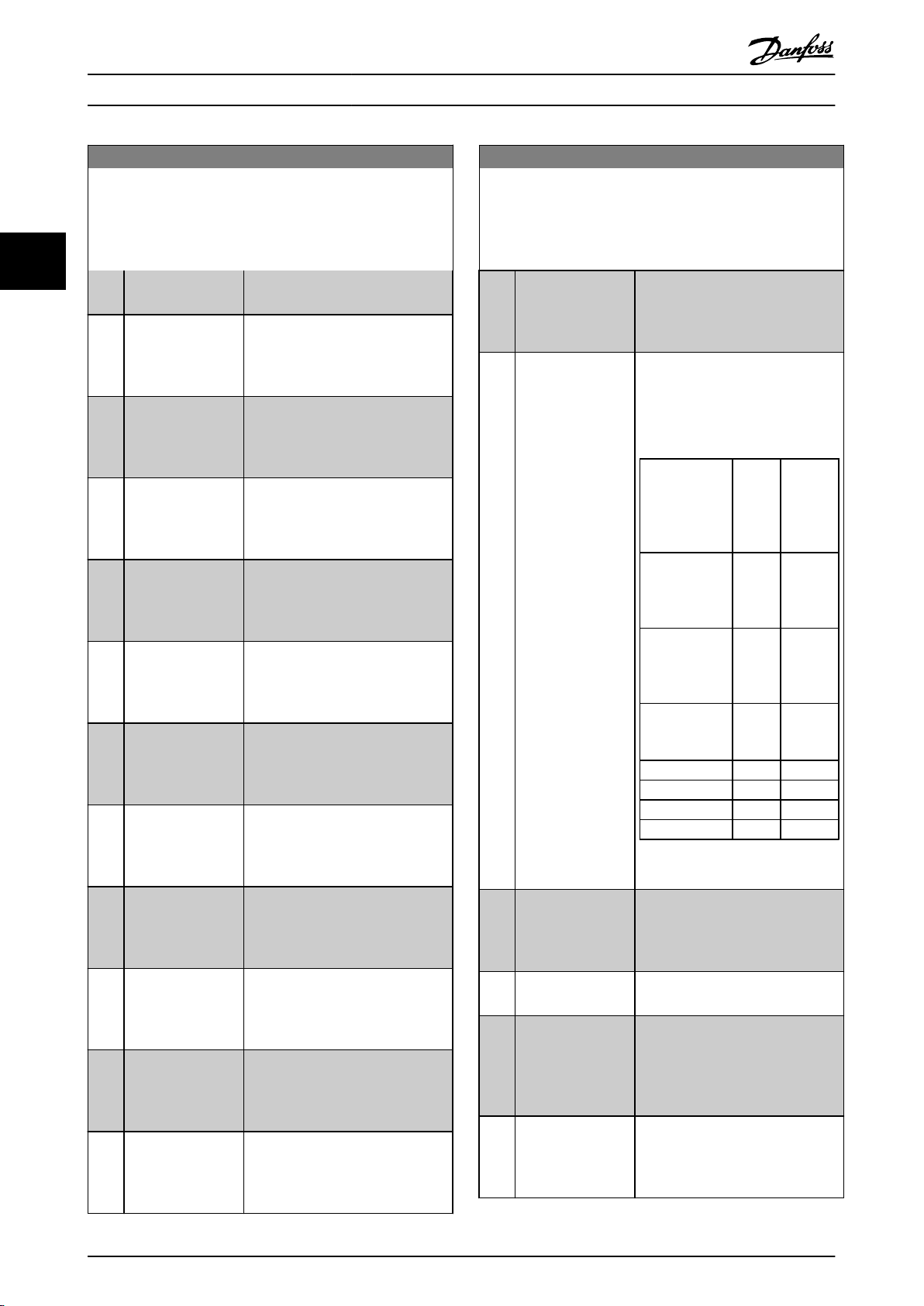
Parameter Descriptions
VLT® AutomationDrive Programming Guide
5-40 Function Relay
Array [9]
1 [0], Relay 2 [1], Relay 3 [2] (MCB 113), Relay 4 [3] (MCB
(Relay
113), Relay 5 [4] (MCB 113), Relay 6 [5] (MCB 113), Relay 7 [6]
(MCB 105), Relay 8 [7] (MCB 105), Relay 9 [8] (MCB 105))
33
Option: Function:
is TRUE, the output will go high.
Otherwise,
[70] Logic rule 0
[71] Logic rule 1
[72] Logic rule 2
[73] Logic rule 3
[74] Logic rule 4
[75] Logic rule 5
[80] SL digital output A
[81] SL digital output B
[82] SL digital output C
[83] SL digital output D
[84] SL digital output E
See parameter group 13-4*
Logic Control. If Logic Rule 0 in SLC
is TRUE, the output will go high.
Otherwise, it will be low.
See parameter group 13-4*
Logic Control. If Logic Rule 1 in SLC
is TRUE, the output will go high.
Otherwise, it will be low.
See parameter group 13-4*
Logic Control. If Logic Rule 2 in SLC
is TRUE, the output will go high.
Otherwise, it will be low.
See parameter group 13-4*
Logic Control. If Logic Rule 3 in SLC
is TRUE, the output will go high.
Otherwise, it will be low.
See parameter group 13-4*
Logic Control. If Logic Rule 4 in SLC
is TRUE, the output will go high.
Otherwise, it will be low.
See parameter group 13-4*
Logic Control. If Logic Rule 5 in SLC
is TRUE, the output will go high.
Otherwise, it will be low.
See 13-52
Output A is low on Smart Logic
Action [32]. Output A is high on
Smart Logic Action [38].
See 13-52
Output B is low on Smart Logic
Action [33]. Output B is high on
Smart Logic Action [39].
See 13-52
Output C is low on Smart Logic
Action [34]. Output C is high on
Smart Logic Action [40].
See 13-52
Output D is low on Smart Logic
Action [35]. Output D is high on
Smart Logic Action [41]
See 13-52
Output E is low on Smart Logic
Action [36]. Output E is high on
Smart Logic Action [42].
it will be low.
Smart
Smart
Smart
Smart
Smart
Smart
SL Controller Action.
SL Controller Action.
SL Controller Action.
SL Controller Action.
SL Controller Action.
5-40 Function Relay
Array [9]
1 [0], Relay 2 [1], Relay 3 [2] (MCB 113), Relay 4 [3] (MCB
(Relay
113), Relay 5 [4] (MCB 113), Relay 6 [5] (MCB 113), Relay 7 [6]
(MCB 105), Relay 8 [7] (MCB 105), Relay 9 [8] (MCB 105))
Option: Function:
[85] SL digital output F
[120] Local ref active
[121] Remote ref active
[122] No alarm Output is high when no alarm is
[123] Start command
activ
[124] Running reverse Output is high when the frequency
See 13-52
Output F is low on Smart Logic
Action [37]. Output F is high on
Smart Logic Action [43].
Output is high when 3-13
Site = [2] Local or when
3-13 Reference Site = [0] Linked to
hand auto at the same time as the
LCP is in [Hand on] mode.
Reference site
set in
3-13 Reference
Site
Reference site:
Local
3-13
Site [2]
Reference site:
Remote
3-13
Site [1]
Reference site:
Linked
Hand/ Auto
Hand 1 0
Hand -> off 1 0
Auto -> off 0 0
Auto 0 1
Output is high when 3-13
Site = Remote [1] or Linked to hand/
auto [0] while the LCP is in [Auto
on] mode. See above.
present.
Output is high when the Start
command
bus connection or [Hand On] or
[Auto On] ), and a Stop has been
last command.
converter
clockwise (the logical product of the
status bits ‘running’ AND ‘reverse’).
SL Controller Action.
Reference
Reference
to
Table 3.18
high (i.e. via digital input,
is running counter
Local
referen
ce
active
[120]
1 0
0 1
Reference
Remote
reference
active
[121]
Reference
84 MG33MF02 - VLT® is a registered Danfoss trademark
Page 86

Selected
Event
Relay
output
Selected
Event
Relay
output
On Delay
P 5-41
On Delay
P 5-41
O Delay
P 5-42
130BA171.10
Selected
Event
Relay
output
On Delay
P 5-41
O Delay
P 5-42
130BA172.10
130BA076.10
(RPM)
Ref.
Low freq.
P 5-50/
P 5-55
Input
(Hz)
High
ref.
value
P 5-53/
p 5-58
High freq.
P 5-51/
P 5-56
Low
ref.
value
P 5-52/
p 5-57
Parameter Descriptions
VLT® AutomationDrive Programming Guide
5-40 Function Relay
Array [9]
1 [0], Relay 2 [1], Relay 3 [2] (MCB 113), Relay 4 [3] (MCB
(Relay
113), Relay 5 [4] (MCB 113), Relay 6 [5] (MCB 113), Relay 7 [6]
(MCB 105), Relay 8 [7] (MCB 105), Relay 9 [8] (MCB 105))
Option: Function:
[125] Drive in hand mode Output is high when the frequency
converter
indicated by the LED light above
[Hand on]).
[126] Drive in auto mode Output is high when the frequency
converter
indicated by LED on above [Auto
on] ).
is in [Hand on] mode (as
is in ‘Auto’ mode (as
Illustration 3.36
the selected Event condition changes before the on- or
If
off delay timer expires, the relay output is unaffected.
3 3
5-41 On Delay, Relay
Array [9], (Relay 1 [0], Relay 2 [1], Relay 3 [2], Relay 4 [3], Relay 5
Relay 6 [5], Relay 7 [6], Relay 8 [7], Relay 9 [8])
[4],
Range: Function:
0.01 s* [0.01 - 600.00 s] Enter the delay of the relay cut-in
The relay will only cut in if the
time.
condition in 5-40 Function Relay is
uninterrupted during the specified
time. Select one of available
mechanical relays and MCB 105 in an
array function. See 5-40 Function Relay.
Relay 3-6 are included in MCB 113.
3.7.5 5-5* Pulse Input
The pulse input parameters are used to define an
appropriate
configuring the scaling and filter settings for the pulse
inputs. Input terminals 29 or 33 act as frequency reference
inputs. Set terminal 29 (5-13 Terminal 29 Digital Input) or
terminal 33 (5-15 Terminal 33 Digital Input) to [32] Pulse
input . If terminal 29 is used as an input, then set
5-01 Terminal 27 Mode to [0] Input.
Illustration 3.37
window for the impulse reference area by
Illustration 3.35
5-42 Off Delay, Relay
Array[2]: Relay1[0], Relay2[1]
Range: Function:
0.01 s* [0.01 - 600.00s]Enter the delay of the relay cut-out
Select one of available
time.
mechanical relays and MCB 105 in an
array function. See 5-40 Function Relay.
MG33MF02 - VLT® is a registered Danfoss trademark
5-50 Term. 29 Low Frequency
Range: Function:
100 Hz* [0 - 110000
Hz]
Enter the low frequency limit
corresponding
speed (i.e. low reference value) in
5-52 Term. 29 Low Ref./Feedb. Value. Refer
to the diagram in this section.
This parameter is available for FC 302
only.
to the low motor shaft
85
Page 87

Parameter Descriptions
VLT® AutomationDrive Programming Guide
5-51 Term. 29 High Frequency
Range: Function:
100 Hz* [0 - 110000
Hz]
33
Enter the high frequency limit
corresponding
speed (i.e. high reference value) in
5-53 Term. 29 High Ref./Feedb. Value.
This parameter is available for FC 302
only.
to the high motor shaft
5-55 Term. 33 Low Frequency
Range: Function:
100 Hz* [0 - 110000
Hz]
Enter the low frequency
corresponding
speed (i.e. low reference value) in
5-57 Term. 33 Low Ref./Feedb. Value.
5-56 Term. 33 High Frequency
to the low motor shaft
Range: Function:
5-52 Term. 29 Low Ref./Feedb. Value
Range: Function:
0.000 Reference-
FeedbackUnit*
[-999999.999 -
999999.999
ReferenceFeedbackUnit]
Enter the low reference
value
limit for the motor
shaft speed [RPM]. This is
also the lowest feedback
value, see also 5-57 Term.
33 Low Ref./Feedb. Value.
Set terminal 29 to digital
input (5-02 Terminal 29
Mode =input [0] (default)
and 5-13 Terminal 29
Digital Input = applicable
value).
This parameter is
available for FC 302 only.
5-53 Term. 29 High Ref./Feedb. Value
Range: Function:
1500.000 ReferenceFeedbackUnit*
[-999999.999 -
999999.999
ReferenceFeedbackUnit]
Enter the high reference
[RPM] for the
value
motor shaft speed and
the high feedback value,
see also 5-58 Term. 33
High Ref./Feedb. Value.
Select terminal 29 as a
digital input
(5-02 Terminal 29 Mode =
[0] input (default) and
5-13 Terminal 29 Digital
Input = applicable value).
This parameter is
available for FC 302 only.
100 Hz* [0 - 110000
Hz]
Enter the high frequency
corresponding to the high motor shaft
speed (i.e. high reference value) in
5-58 Term. 33 High Ref./Feedb. Value.
5-57 Term. 33 Low Ref./Feedb. Value
Range: Function:
0.000 * [-999999.999 -
999999.999
]
Enter the low reference value
[RPM] for the motor shaft speed.
This is also the low feedback
value, see also 5-52 Term. 29 Low
Ref./Feedb. Value.
5-58 Term. 33 High Ref./Feedb. Value
Range: Function:
1500.000 ReferenceFeedbackUnit*
[-999999.999 -
999999.999
ReferenceFeedbackUnit]
Enter the high
reference
[RPM] for the motor
shaft speed. See
also 5-53 Term. 29
High Ref./Feedb.
Value.
5-59 Pulse Filter Time Constant #33
Range: Function:
100 ms* [1 - 1000
ms]
Enter the pulse filter time constant. The
low-pass
and dampens oscillations on the feedback
signal from the control.
This is an advantage, e.g. if there is a
great amount on noise in the system.
filter reduces the influence on
value
NOTE
This
5-54 Pulse Filter Time Constant #29
Range: Function:
100
ms*
[1 1000
Enter the pulse filter time constant. The
ms]
pulse filter dampens oscillations of the
feedback signal, which is an advantage if
there is a lot of noise in the system. A high
time constant value results in better
dampening but also increases the time delay
through the filter. This parameter is available
for FC 302 only.
This parameter cannot be adjusted while the
motor is running.
parameter cannot be adjusted while the motor is
running.
3.7.6 5-6* Pulse Outputs
These parameters are to configure pulse outputs with their
functions
pulse output via 5-01 Terminal 27 Mode and 5-02 Terminal
29 Mode, respectively.
and scaling. Terminal 27 and 29 are allocated to
86 MG33MF02 - VLT® is a registered Danfoss trademark
Page 88

Output value
Output
(Hz)
High output
value
P 5-60(term27)
P 5-63(term29)
High freq.
P 5-62(term27)
P 5-65(term29)
130BA089.11
Parameter Descriptions
VLT® AutomationDrive Programming Guide
NOTE
parameters cannot be adjusted while the motor is
These
running.
Illustration 3.38
Options for readout output variables:
Parameters for configuring the
and output functions of
scaling
pulse outputs. The pulse outputs
are designated to terminals 27 or
29. Select terminal 27 output in
5-01 Terminal 27 Mode and
terminal 29 output in
5-02 Terminal 29 Mode.
[0] No operation
[45] Bus control
[48] Bus control time-out
[51] MCO controlled
[100] Output frequency
[101] Reference
[102] Feedback
[103] Motor current
[104] Torque relative to limit
[105] Torque relative to rated
[106] Power
[107] Speed
[108] Torque
[109] Max Out Freq
5-60 Terminal 27 Pulse Output Variable
Option: Function:
[0] * No operation Select the desired display output for
27.
terminal
[45] Bus ctrl.
[48] Bus ctrl., timeout
[51] MCO controlled
[100] Output frequency
[101] Reference
[102] Feedback
5-60 Terminal 27 Pulse Output Variable
Option: Function:
[103] Motor current
[104] Torque rel to limit
[105] Torq relate to rated
[106] Power
[107] Speed
[108] Torque
[109] Max Out Freq
[119] Torque % lim
5-62 Pulse Output Max Freq #27
Range: Function:
5000. Hz* [0 - 32000 Hz] Set the maximum frequency for
27, corresponding to the
terminal
output variable selected in
5-60 Terminal 27 Pulse Output
Variable.
5-63 Terminal 29 Pulse Output Variable
Option: Function:
[0] * No operation Select the desired display output for
29. This parameter is
terminal
available for FC 302 only.
[45] Bus ctrl.
[48] Bus ctrl., timeout
[51] MCO controlled
[100] Output frequency
[101] Reference
[102] Feedback
[103] Motor current
[104] Torque rel to limit
[105] Torq relate to rated
[106] Power
[107] Speed
[108] Torque
[109] Max Out Freq
[119] Torque % lim
5-65 Pulse Output Max Freq #29
Set the maximum frequency for terminal 29 corresponding to the
variable set in 5-63 Terminal 29 Pulse Output Variable.
output
Range: Function:
5000 Hz* [0 - 32000 Hz]
5-66 Terminal X30/6 Pulse Output Variable
Select the variable for read-out on terminal X30/6.
parameter is active when option module MCB 101 is
This
installed in the frequency converter.
Same options and functions as parameter group 5-6*.
Option: Function:
[0] * No operation
[45] Bus ctrl.
[48] Bus ctrl., timeout
3 3
MG33MF02 - VLT® is a registered Danfoss trademark
87
Page 89

130BA090.11
+24V DC
A
B
GND
1312 18 37322719 29 33 20
24V or 10-30V encoder
B
A
B
A
130BA646.10
CW
CCW
Parameter Descriptions
VLT® AutomationDrive Programming Guide
5-66 Terminal X30/6 Pulse Output Variable
Select the variable for read-out on terminal X30/6.
parameter is active when option module MCB 101 is
This
installed in the frequency converter.
Same options and functions as parameter group 5-6*.
33
Option: Function:
[51] MCO controlled
[100] Output frequency
[101] Reference
[102] Feedback
[103] Motor current
[104] Torque rel to limit
[105] Torq relate to rated
[106] Power
[107] Speed
[108] Torque
[109] Max Out Freq
[119] Torque % lim
NOTE
This
parameter cannot be adjusted while the motor is
running.
5-68 Pulse Output Max Freq #X30/6
Select the maximum frequency on terminal X30/6 referring to
output variable in 5-66 Terminal X30/6 Pulse Output Variable.
the
This parameter is active when option module MCB 101 is
mounted in the frequency converter.
Range: Function:
5000. Hz* [0 - 32000 Hz]
3.7.7 5-7* 24 V Encoder Input
Connect the 24 V encoder to terminal 12 (24 V DC supply),
terminal
terminal 20 (GND). The digital inputs 32/33 are active for
32 (Channel A), terminal 33 (Channel B), and
encoder inputs when [1] 24 V encoder is selected in
1-02 Flux Motor Feedback Source and 7-00 Speed PID
Feedback Source. The encoder used is a dual channel (A
and B) 24 V type. Max input frequency: 110 kHz.
Encoder Connection to the frequency converter
24 V incremental encoder. Max. cable length 5 m.
Illustration 3.39
Illustration 3.40
5-70 Term 32/33 Pulses per Revolution
Range: Function:
1024 N/A* [1 - 4096 N/A] Set the encoder pulses per
revolution
the correct value from the encoder.
88 MG33MF02 - VLT® is a registered Danfoss trademark
on the motor shaft. Read
Page 90

Parameter Descriptions
VLT® AutomationDrive Programming Guide
NOTE
parameter cannot be adjusted while the motor is
This
running.
5-71 Term 32/33 Encoder Direction
Option: Function:
Change the detected encoder rotation
direction
the encoder.
[0] * Clockwise Sets channel A 90° (electrical degrees)
behind
of the encoder shaft.
[1] Counter
clockwise
Sets channel A 90° (electrical degrees)
ahead
rotation of the encoder shaft.
without changing the wiring to
channel B upon clockwise rotation
of channel B upon clockwise
NOTE
This
parameter cannot be adjusted while the motor is
running.
3.7.8 5-8* I/O Options
5-80 AHF Cap Reconnect Delay
Range: Function:
25 s* [1 - 120s]Guarantees a minimum off-time for the
capacitors.
capacitor disconnects and needs to expire
before the output is allowed to be on again. It
will only turn on again if the drive power is
between 20% and 30%.
3.7.9 5-9*
This parameter group selects digital and relay outputs via
a
fieldbus setting.
5-90 Digital & Relay Bus Control
Range: Function:
0 N/A* [0 - 2147483647
N/A]
The timer starts once the AHF
This parameter holds the state of
the
digital outputs and relays that is
controlled by bus.
A logical '1' indicates that the
output is high or active.
A logical '0' indicates that the
output is low or inactive.
Bit 0 Digital Output Terminal 27
Bit 1 Digital Output Terminal 29
Bit 2 Digital Output Terminal X 30/6
Bit 3 Digital Output Terminal X 30/7
Bit 4 Relay 1 output terminal
Bit 5 Relay 2 output terminal
Bit 6 Option B Relay 1 output terminal
Bit 7 Option B Relay 2 output terminal
Bit 8 Option B Relay 3 output terminal
Bit 9-15 Reserved for future terminals
Bit 16 Option C Relay 1 output terminal
Bit 17 Option C Relay 2 output terminal
Bit 18 Option C Relay 3 output terminal
Bit 19 Option C Relay 4 output terminal
Bit 20 Option C Relay 5 output terminal
Bit 21 Option C Relay 6 output terminal
Bit 22 Option C Relay 7 output terminal
Bit 23 Option C Relay 8 output terminal
Bit 24-31 Reserved for future terminals
Table 3.19
5-93 Pulse Out #27 Bus Control
Range: Function:
0.00 %* [0.00 - 100.00%]Set the output frequency transferred to
output terminal 27 when the
the
terminal is configured as [45] Bus
Controlled in 5-60 Terminal 27 Pulse
Output Variable.
5-94 Pulse Out #27 Timeout Preset
Range: Function:
0.00 %* [0.00 -
100.00
%]
Set the output frequency transferred to
the output terminal 27 when the
terminal is configured as [48] Bus Ctrl
Timeout in 5-60 Terminal 27 Pulse Output
Variable. And a time-out is detected.
5-95 Pulse Out #29 Bus Control
Range: Function:
0.00 %* [0.00 -
100.00
%]
Set the output frequency transferred to
the output terminal 29 when the
terminal is configured as [45] Bus
Controlled in 5-63 Terminal 29 Pulse
Output Variable.
This parameter only applies for FC 302.
3 3
5-96 Pulse Out #29 Timeout Preset
Range: Function:
0.00 %* [0.00 -
100.00 %]
MG33MF02 - VLT® is a registered Danfoss trademark
Set the output frequency transferred to
the output terminal 29 when the
terminal is configured as [48] Bus Ctrl
Timeout in 5-63 Terminal 29 Pulse Output
Variable. And a time-out is detected.
This parameter only applies for FC 302.
89
Page 91

Parameter Descriptions
VLT® AutomationDrive Programming Guide
5-97 Pulse Out #X30/6 Bus Control
Range: Function:
0 %* [0 - 100 %] Set the output frequency transferred to the
terminal X30/6 when the terminal is
output
configured as 'Bus Controlled' in
33
5-66 Terminal X30/6 Pulse Output Variable,
Terminal X30/6 Pulse Output Variable [45].
5-98 Pulse Out #X30/6 Timeout Preset
Range: Function:
0 %* [0 - 100 %] Set the output frequency transferred to the
output
terminal X30/6 when the terminal is
configured as [48] Bus Ctrl Timeout in
5-66 Terminal X30/6 Pulse Output Variable.
And a time-out is detected.
90 MG33MF02 - VLT® is a registered Danfoss trademark
Page 92
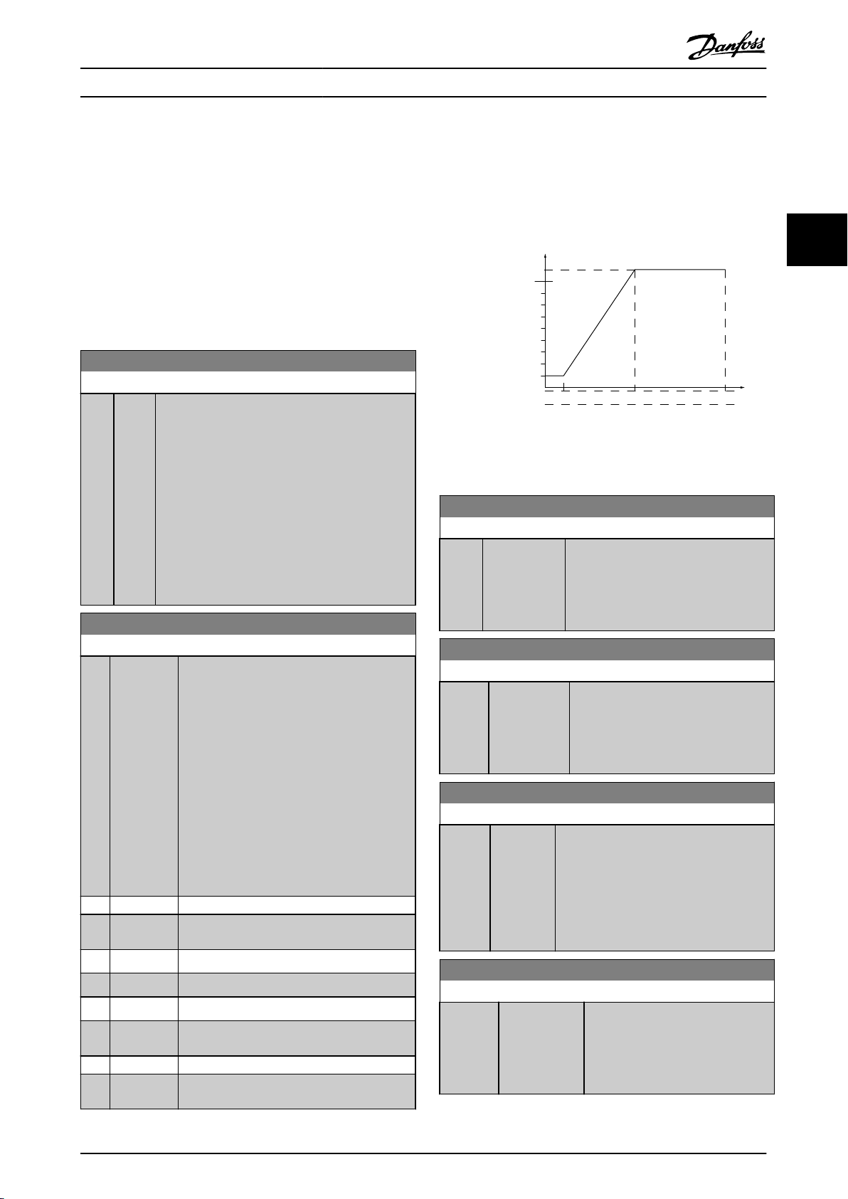
Ex. 5 V 10 V
300
600
900
1200
1500
150
130BT103.10
1 V
Par 6-xx
'Low Voltage'or
'Low Current'
Par 6-xx
'High Voltage'or
'High Current'
Analog input
Ref./Feedback
[RPM]
Par 6-xx
'High Ref./
Feedb. Value'
Par 6-xx
'Low Ref./
Feedb. Value'
Parameter Descriptions
VLT® AutomationDrive Programming Guide
3.8 Parameters: 6-** Analog In/Out
3.8.1 6-0* Analog I/O Mode
The analog inputs can freely be allocated to be either
(FC 301: 0..10 V, FC 302: 0..± 10 V) or current (FC
voltage
301/FC 302: 0/4..20 mA) input.
NOTE
Thermistors
digital input.
6-00 Live Zero Timeout Time
Range: Function:
10 s* [1 -
6-01 Live Zero Timeout Function
Option: Function:
[0] * Off
[1] Freeze
[2] Stop Overruled to stop
[3] Jogging Overruled to jog speed
[4] Max. speed Overruled to max. speed
[5] Stop and
[20] Coast
[21] Coast and
may be connected to either an analog or a
Enter the Live Zero Time-out time period. Live
99
s]
Zero Time-out Time is active for analog inputs, i.e.
terminal 53 or terminal 54, used as reference or
feedback sources. If the reference signal value
associated with the selected current input falls
below 50% of the value set in 6-10 Terminal 53
Low Voltage, 6-12 Terminal 53 Low Current,
6-20 Terminal 54 Low Voltage or 6-22 Terminal 54
Low Current for a time period longer than the time
set in 6-00 Live Zero Timeout Time, the function
selected in 6-01 Live Zero Timeout Function will be
activated.
Select the time-out function. The function set
6-01 Live Zero Timeout Function will be
in
activated if the input signal on terminal 53 or
54 is below 50% of the value in 6-10 Terminal
53 Low Voltage, 6-12 Terminal 53 Low Current,
6-20 Terminal 54 Low Voltage or 6-22 Terminal
54 Low Current for a time period defined in
6-00 Live Zero Timeout Time. If several time-
outs occur simultaneously, the frequency
converter prioritises the time-out functions as
follows:
1.
6-01 Live Zero Timeout Function
2.
8-04 Control Word Timeout Function
Frozen at the present value
output
Overruled to stop with subsequent trip
trip
trip
MG33MF02 - VLT® is a registered Danfoss trademark
3.8.2 6-1* Analog Input 1
Parameters for configuring the scaling and limits for
input 1 (terminal 53).
analog
Illustration 3.41
6-10 Terminal 53 Low Voltage
Range: Function:
0.07 V* [-10.00 - par.
6-11
V]
6-11 Terminal 53 High Voltage
Range: Function:
10.00 V* [ par.
10.00 V]
6-12 Terminal 53 Low Current
Range: Function:
0.14
mA*
[0.00 -
6-13
par.
mA]
6-13 Terminal 53 High Current
Range: Function:
20.00 mA* [ par.
20.00 mA]
Enter the low voltage value. This analog
input scaling value should correspond
to the minimum reference value, set in
6-14 Terminal 53 Low Ref./Feedb. Value.
See also the section Reference Handling.
6-10 -
Enter the high voltage value. This
analog input scaling value should
correspond to the high reference/
feedback value set in 6-15 Terminal 53
High Ref./Feedb. Value.
Enter the low current value. This reference
signal should correspond to the minimum
reference value, set in 3-02 Minimum
Reference. The value must be set at >2 mA
in order to activate the Live Zero Time-out
Function in 6-01 Live Zero Timeout
Function.
6-12 -
Enter the high current value
corresponding to the high
reference/feedback set in
6-15 Terminal 53 High Ref./Feedb.
Value.
3 3
91
Page 93
Parameter Descriptions
VLT® AutomationDrive Programming Guide
6-14 Terminal 53 Low Ref./Feedb. Value
Range: Function:
0.000 * [-999999.999 -
999999.999
]
33
Enter the analog input scaling
value that corresponds to the low
voltage/low current set in
6-10 Terminal 53 Low Voltage and
6-12 Terminal 53 Low Current.
6-15 Terminal 53 High Ref./Feedb. Value
6-22 Terminal 54 Low Current
Range: Function:
0.14
mA*
[0.00 -
6-23
par.
mA]
Enter the low current value. This reference
signal should correspond to the minimum
reference value, set in 3-02 Minimum
Reference. The value must be set at >2 mA
in order to activate the Live Zero Time-out
Function in 6-01 Live Zero Timeout
Function.
Range: Function:
1500.000 ReferenceFeedbackUnit*
[-999999.999 -
999999.999
ReferenceFeedbackUnit]
6-16 Terminal 53 Filter Time Constant
Range: Function:
0.001 s* [0.001 -
10.000
s]
Enter the time constant. This is a firstorder digital low pass filter time
constant for suppressing electrical noise
in terminal 53. A high time constant
value improves dampening but also
increases the time delay through the
filter.
Enter the analog input
scaling
value that
corresponds to the
maximum reference
feedback value set in
6-11 Terminal 53 High
Voltage and
6-13 Terminal 53 High
Current.
6-23 Terminal 54 High Current
Range: Function:
20.00 mA* [ par.
20.00 mA]
6-22 -
Enter the high current value
corresponding to the high reference/
feedback value set in 6-25 Terminal
54 High Ref./Feedb. Value.
6-24 Terminal 54 Low Ref./Feedb. Value
Range: Function:
0 ReferenceFeedbackUnit*
[-999999.999 -
999999.999
ReferenceFeedbackUnit]
Enter the analog
scaling value
input
that corresponds to
the minimum
reference feedback
value set in
3-02 Minimum
Reference.
6-25 Terminal 54 High Ref./Feedb. Value
Range: Function:
NOTE
This
parameter cannot be adjusted while the motor is
running.
3.8.3 6-2* Analog Input 2
Parameters for configuring the scaling and limits for
analog
input 2 (terminal 54).
1500.000 ReferenceFeedbackUnit*
[-999999.999 -
999999.999
ReferenceFeedbackUnit]
Enter the analog input
value that
scaling
corresponds to the
maximum reference
feedback value set in
3-03 Maximum
Reference.
6-26 Terminal 54 Filter Time Constant
6-20 Terminal 54 Low Voltage
Range: Function:
0.07 V* [-10.00 - par.
V]
6-21
Enter the low voltage value. This analog
input scaling value should correspond
to the minimum reference value, set in
3-02 Minimum Reference. See also
3.5 Parameters: 3-** Reference/Ramps.
6-21 Terminal 54 High Voltage
Range: Function:
10.00 V* [ par.
10.00 V]
6-20 -
Enter the high voltage value. This
analog input scaling value should
correspond to the high reference/
feedback value set in 6-25 Terminal 54
High Ref./Feedb. Value.
Range: Function:
0.001 s* [0.001 s]
10.000
Enter the time constant. This is a firstorder digital low pass filter time
constant for suppressing electrical noise
in terminal 54. A high time constant
value improves dampening but also
increases the time delay through the
filter.
NOTE
This
parameter cannot be adjusted while the motor is
running.
92 MG33MF02 - VLT® is a registered Danfoss trademark
Page 94
Parameter Descriptions
VLT® AutomationDrive Programming Guide
3.8.4 6-3* Analog Input 3 MCB 101
Parameter group for configuring the scale and limits for
input 3 (X30/11) placed on option module MCB
analog
101.
6-30 Terminal X30/11 Low Voltage
Range: Function:
- par.
0.07 V* [ 0.00
6-31 V]
Sets the analog input scaling value to
correspond to the low reference/
feedback value (set in 6-34 Term.
X30/11 Low Ref./Feedb. Value).
6-31 Terminal X30/11 High Voltage
Range: Function:
6-30 -
10.00 V* [ par.
10.00 V]
Sets the analog input scaling value to
correspond to the high reference/
feedback value (set in 6-35 Term.
X30/11 High Ref./Feedb. Value).
6-34 Term. X30/11 Low Ref./Feedb. Value
Range: Function:
0.000 * [-999999.999 -
999999.999
]
Sets the analog input scaling
value to correspond to the low
voltage value (set in 6-30 Terminal
X30/11 Low Voltage).
6-35 Term. X30/11 High Ref./Feedb. Value
Range: Function:
100.000 * [-999999.999 -
999999.999
]
Sets the analog input scaling
value to correspond to the high
voltage value (set in
6-31 Terminal X30/11 High
Voltage).
6-36 Term. X30/11 Filter Time Constant
Range: Function:
0.001 s* [0.001 - 10.000 s]
A 1st
order digital low pass filter
time constant for suppressing
electrical noise on terminal X30/11.
NOTE
parameter cannot be adjusted while the motor is
This
running.
3.8.5 6-4* Analog Input 4 MCB 101
Parameter group for configuring the scale and limits for
analog
input 4 (X30/12) placed on option module MCB
101.
6-40 Terminal X30/12 Low Voltage
Range: Function:
- par.
0.07 V* [ 0.00
6-41 V]
Sets the analog input scaling value to
correspond to the low reference/
6-40 Terminal X30/12 Low Voltage
Range: Function:
feedback value set in 6-44
X30/12 Low Ref./Feedb. Value.
Term.
6-41 Terminal X30/12 High Voltage
Range: Function:
6-40 -
10.00 V* [ par.
10.00 V]
Sets the analog input scaling value to
correspond to the high reference/
feedback value set in 6-45 Term.
X30/12 High Ref./Feedb. Value.
6-44 Term. X30/12 Low Ref./Feedb. Value
Range: Function:
0.000 * [-999999.999 -
999999.999
]
Sets the analog output scaling
value to correspond to the low
voltage value set in 6-40 Terminal
X30/12 Low Voltage.
6-45 Term. X30/12 High Ref./Feedb. Value
Range: Function:
100.000 * [-999999.999 -
999999.999
]
Sets the analog input scaling
value to correspond to the high
voltage value set in
6-41 Terminal X30/12 High
Voltage.
6-46 Term. X30/12 Filter Time Constant
Range: Function:
0.001 s* [0.001 - 10.000 s]
order digital low pass filter
A 1st
time constant for suppressing
electrical noise on terminal X30/12.
NOTE
This
parameter cannot be adjusted while the motor is
running.
3.8.6 6-5* Analog Output 1
Parameters for configuring the scaling and limits for
analog
output 1, i.e. Terminal 42. Analog outputs are
current outputs: 0/4 to 20 mA. Common terminal (terminal
39) is the same terminal and has the same electrical
potential for analog common and digital common
connection. Resolution on analog output is 12 bit.
6-50 Terminal 42 Output
Option: Function:
Select the function of Terminal 42 as an
current output. Depending on the
analog
selection the output is either a 0-20 mA or
4-20 mA output. The current value can be
read out in LCP in 16-65 Analog Output 42
[mA].
3 3
MG33MF02 - VLT® is a registered Danfoss trademark
93
Page 95

0mA 12 mA 20 mA 4mA
Par 4-17
(200%)
Par 4-16
(200%)
0% Torque
130BB372.10
Parameter Descriptions
VLT® AutomationDrive Programming Guide
6-50 Terminal 42 Output
Option: Function:
[0] * No
operation
[52] MCO
33
0-20mA
[53] MCO
4-20mA
[100] Output
frequency
[101] Reference
[102] Feedback
[103] Motor
current
[104] Torque rel
limit
to
[105] Torq relate
rated
to
[106] Power
[107] Speed
[108] Torque Torque reference related to 160% torque.
[109] Max Out
Freq
[119] Torque %
lim
[130] Output
freq.
4-20mA
[131] Reference
4-20mA
When no signal on the analog output.
0 Hz = 0 mA; 100 Hz = 20 mA.
3-00 Reference Range
[Min - Max] 0% = 0 mA;
100% = 20 mA
3-00 Reference Range [-Max - Max] -100% = 0
mA; 0% = 10 mA; +100% = 20 mA
Value is taken from 16-37
Inv. Max. Current.
Inverter max. current (160% current) is equal
to 20 mA.
Example: Inverter norm current (11 kW) = 24
A. 160% = 38.4 A. Motor norm current = 22 A
Read-out 11.46 mA.
mA x
22
38.4
A
= 11.46
A
mA
20
In case the norm motor current is equal to 20
mA, the output setting of 6-52 Terminal 42
Output Max Scale is:
I
x 100
VLT
I
Motor
Max
Norm
x
100
38.4
=
= 175 %
22
The torque setting is related to setting in
4-16 Torque Limit Motor Mode
The torque is related to the motor torque
setting.
Taken from 1-20
Taken from 3-03
Motor Power [kW].
Maximum Reference. 20 mA =
value in 3-03 Maximum Reference
0 Hz = 0 mA,4-19
Max Output Frequency = 20
mA.
0 Hz = 4 mA, 100 Hz = 20 mA
3-00 Reference Range
[Min-Max] 0% = 4 mA;
100% = 20 mA
6-50 Terminal 42 Output
Option: Function:
Example: Inverter norm current (11 kW) = 24
160% = 38.4 A. Motor norm current = 22 A
A.
Read-out 11.46 mA.
16
mA x
38.4
In case the norm motor current is equal to 20
mA, the output setting of 6-62 Terminal X30/8
Max. Scale is:
I
VLT
Max
I
Motor
[134] Torq.% lim
mA
4-20
[135] Torq.%
4-20
nom
mA
[136] Power
4-20mA
[137] Speed
4-20mA
[138] Torque
4-20mA
[139] Bus ctrl.
mA
0-20
[140] Bus ctrl.
mA
4-20
[141] Bus ctrl
0-20mA
[142] Bus ctrl
4-20mA
[149] Torque %
4-20mA
lim
The torque setting is related to setting in
4-16 Torque Limit Motor Mode.
The torque setting is related to the motor
torque setting.
Taken from 1-20
Taken from 3-03
Value in 3-03 Maximum Reference.
Torque reference related to 160% torque.
An output value set from fieldbus process
data. The output will work independently of
internal functions in the frequency converter.
An output value set from fieldbus process
data. The output will work independently of
internal functions in the frequency converter.
4-54 Warning Reference Low defines the
t.o.
behaviour of the analog output in case of bus
time-out.
4-54 Warning Reference Low defines the
t.o.
behaviour of the analog output in case of bus
time-out.
Analog output at zero torque = 12 mA.
Motoric torque will increase the output
current to max torque limit 20 mA (set in
4-16 Torque Limit Motor Mode).
Generative torque will decrease the output to
torque limit Generator Mode (set in
4-17 Torque Limit Generator Mode)
Ex: 4-16 Torque Limit Motor Mode: 200% and
4-17 Torque Limit Generator Mode: 200%. 20
mA = 200% Motoric and 4 mA = 200%
Generatoric.
22
A
x 100
Norm
A
+ 4 mA= 13.17
38.4
=
mA
x
100
= 175 %
22
Motor Power [kW]
Maximum Reference. 20 mA =
3-00 Reference Range [-Max-Max] -100% = 4
mA; 0% = 12 mA; +100% = 20 mA
[132] Feedback
4-20mA
[133] Motor cur.
4-20mA
Value is taken from 16-37
Inv. Max. Current.
Inverter max. current (160% current) is equal
Illustration 3.42
to 20 mA.
94 MG33MF02 - VLT® is a registered Danfoss trademark
Page 96

130BA075.12
(mA)
0%
20
0/4
100%
Current
Analogue
output
Min Scale
par. 6-93
Variable
for
output
example:
Speed
(RPM)
Analogue
Output
Max Scale
par. 6-94
Parameter Descriptions
VLT® AutomationDrive Programming Guide
6-50 Terminal 42 Output
Option: Function:
[150] Max Out Fr
4-20mA
0 Hz = 0 mA,4-19
mA.
Max Output Frequency = 20
6-51 Terminal 42 Output Min Scale
Range: Function:
0.00 %* [0.00 -
200.00
%]
Scale for the minimum output (0 or 4
mA) of the analog signal at terminal 42.
Set the value to be the percentage of
the full range of the variable selected in
6-50 Terminal 42 Output.
6-52 Terminal 42 Output Max Scale
Range: Function:
100.00%* [0.00 -
200.00
20
mA
/
desired maximum current x
i.e
. 10 mA :
20
10
Illustration 3.43
Scale the maximum output of the selected
%]
analog signal at terminal 42. Set the value
to the maximum value of the current signal
output. Scale the output to give a current
lower than 20 mA at full scale; or 20 mA at
an output below 100% of the maximum
signal value. If 20 mA is the desired output
current at a value between 0 - 100% of the
full-scale output, programme the
percentage value in the parameter, i.e. 50%
= 20 mA. If a current between 4 and 20 mA
is desired at maximum output (100%),
calculate the percentage value as follows:
100 %
x
100 = 200 %
6-53 Terminal 42 Output Bus Control
Range: Function:
0.00 %* [0.00 - 100.00 %] Holds the level of Output 42 if
controlled
by bus.
6-54 Terminal 42 Output Timeout Preset
Range: Function:
0.00 %* [0.00 -
100.00 %]
Holds the preset level of Output 42.
In case of a bus timeout and a timeout
function is selected in 6-50 Terminal 42
MG33MF02 - VLT® is a registered Danfoss trademark
6-54 Terminal 42 Output Timeout Preset
Range: Function:
the output will preset to this
Output
level.
6-55 Analog Output Filter
Option: Function:
The following readout analog parameters from
selection
in 6-50 Terminal 42 Output have a filter
selected when 6-55 Analog Output Filter is on:
Selection 0-20 mA 4-20 mA
Motor current (0 - I
Torque limit (0 - T
Rated torque (0 - T
Power (0 - P
nom
Speed (0 - Speed
) [103] [133]
max
) [104] [134]
lim
) [105] [135]
nom
) [106] [136]
) [107] [137]
max
Table 3.20
[0] * Off Filter off
[1] On Filter on
3.8.7 6-6* Analog Output 2 MCB 101
Analog outputs are current outputs: 0/4 - 20 mA. Common
terminal (terminal X30/8) is the same terminal and
electrical potential for analog common connection.
Resolution on analog output is 12 bit.
6-60 Terminal X30/8 Output
Option: Function:
Select the function of Terminal X30/8 as an
current output. Depending on the
analog
selection the output is either a 0-20 mA or
4-20 mA output. The current value can be
read out in LCP in 16-65 Analog Output 42
[mA].
[0] * No
operation
[52] MCO
0-20mA
[53] MCO
4-20mA
[100] Output
frequency
[101] Reference
[102] Feedback
[103] Motor
current
When no signal on the analog output.
0 Hz = 0 mA; 100 Hz = 20 mA.
3-00 Reference Range
[Min - Max] 0% = 0 mA;
100% = 20 mA
3-00 Reference Range [-Max - Max] -100% = 0
mA; 0% = 10 mA; +100% = 20 mA
Value is taken from 16-37
Inv. Max. Current.
Inverter max. current (160% current) is equal
to 20 mA.
3 3
95
Page 97

Parameter Descriptions
VLT® AutomationDrive Programming Guide
6-60 Terminal X30/8 Output
Option: Function:
Example: Inverter norm current (11 kW) = 24
160% = 38.4 A. Motor norm current = 22 A
A.
Read-out 11.46 mA.
20
mA x
22
A
= 11.46
33
38.4
A
In case the norm motor current is equal to 20
mA, the output setting of 6-62 Terminal X30/8
Max. Scale is:
I
x 100
VLT
Max
I
Motor
Norm
[104] Torque rel
limit
to
[105] Torq relate
rated
to
[106] Power
[107] Speed
The torque setting is related to setting in
4-16 Torque Limit Motor Mode.
The torque is related to the motor torque
setting.
Taken from 1-20
Taken from 3-03
= value in 3-03 Maximum Reference
[108] Torque Torque reference related to 160% torque.
[109] Max Out
In relation to 4-19
Freq
[119] Torque %
lim
[130] Output
0 Hz = 4 mA, 100 Hz = 20 mA
freq.
4-20mA
[131] Reference
4-20mA
3-00 Reference Range
100% = 20 mA
3-00 Reference Range [-Max-Max] -100% = 4
mA; 0% = 12 mA; +100% = 20 mA
[132] Feedback
4-20mA
[133] Motor cur.
4-20mA
Value is taken from 16-37
Inverter max. current (160% current) is equal
to 20 mA.
Example: Inverter norm current (11 kW) = 24
A. 160% = 38.4 A. Motor norm current = 22 A
Read-out 11.46 mA.
mA x
22
38.4
A
A
16
mA
38.4
x
100
=
= 175 %
22
Motor Power [kW].
Maximum Reference. 20 mA
Max Output Frequency.
[Min-Max] 0% = 4 mA;
Inv. Max. Current.
= 9.17
mA
6-60 Terminal X30/8 Output
Option: Function:
[136] Power
4-20mA
[137] Speed
4-20mA
[138] Torque
4-20mA
[139] Bus ctrl.
mA
0-20
[140] Bus ctrl.
mA
4-20
[141] Bus ctrl
0-20mA
[142] Bus ctrl
4-20mA
[149] Torque %
4-20mA
lim
[150] Max Out Fr
4-20mA
Taken from 1-20
Taken from 3-03
= Value in 3-03 Maximum Reference.
Torque reference related to 160% torque.
An output value set from fieldbus process
data. The output will work independently of
internal functions in the frequency converter.
An output value set from fieldbus process
data. The output will work independently of
internal functions in the frequency converter.
4-54 Warning Reference Low defines the
t.o.
behaviour of the analog output in case of
bus time-out.
4-54 Warning Reference Low defines the
t.o.
behaviour of the analog output in case of
bus time-out.
Torque% Lim 4-20 mA: Torque reference.
3-00 Reference Range [Min-Max] 0% = 4 mA;
100% = 20 mA
3-00 Reference Range [-Max - Max] -100% = 4
mA; 0% = 12 mA; +100% = 20 mA
In relation to 4-19
6-61 Terminal X30/8 Min. Scale
Range: Function:
0.00%* [0.00 -
200.00
Scales the minimum output of the selected
%]
analog signal on terminal X30/8. Scale the
minimum value as a percentage of the
maximum signal value, i.e. 0 mA (or 0 Hz) is
desired at 25% of the maximum output value
and 25% is programmed. The value can
never be higher than the corresponding
setting in 6-62 Terminal X30/8 Max. Scale if
value is below 100%.
This parameter is active when option module
MCB 101 is mounted in the frequency
converter.
Motor Power [kW]
Maximum Reference. 20 mA
Max Output Frequency.
In case the norm motor current is equal to 20
[134] Torq.% lim
mA
4-20
[135] Torq.%
4-20
nom
mA
mA, the output setting of 6-62 Terminal X30/8
Max. Scale is:
I
x 100
VLT
Max
I
Motor
Norm
x
100
38.4
=
= 175 %
22
The torque setting is related to setting in
4-16 Torque Limit Motor Mode.
The torque setting is related to the motor
torque setting.
6-62 Terminal X30/8 Max. Scale
Range: Function:
100.00%* [0.00 -
200.00
%]
Scales the maximum output of the selected
signal on terminal X30/8. Scale the
analog
value to the desired maximum value of the
current signal output. Scale the output to
give a lower current than 20 mA at full
scale or 20 mA at an output below 100% of
the maximum signal value. If 20 mA is the
desired output current at a value between 0
- 100% of the ful-scale output, program the
96 MG33MF02 - VLT® is a registered Danfoss trademark
Page 98

Parameter Descriptions
VLT® AutomationDrive Programming Guide
6-62 Terminal X30/8 Max. Scale
Range: Function:
percentage value in the parameter, i.e. 50%
20 mA. If a current between 4 and 20 mA
=
is desired at maximum output (100%),
calculate the percentage value as follows:
mA
/
desired maximum current x
20
i.e
. 10 mA :
20 − 4
10
x
100 = 160 %
100 %
6-63 Terminal X30/8 Bus Control
Range: Function:
0 %* [0 - 100 %] Holds the level of Output X30/8 if controlled
bus.
by
6-64 Terminal X30/8 Output Timeout Preset
Range: Function:
0 %* [0 - 100 %] Holds the preset level of Output X30/8.
case of a bus timeout and a timeout
In
function is selected in 6-60 Terminal X30/8
Output, the output will preset to this level.
3.8.8 6-7* Analog Output 3 MCB 113
Parameters for configuring the scaling and limits for
analog
output 3, Terminal X45/1 and X45/2. Analog
outputs are current outputs: 0/4–20 mA. Resolution on
analog output is 11 bit.
6-70 Terminal X45/1 Output
Option: Function:
Select the function of Terminal X45/1 as an
analog current output.
[0] No
operation
[52] MCO 305
mA
0-20
[53] MCO 305
mA
4-20
[100] Output
frequency
mA
0-20
[101] Reference
mA
0-20
[102] Feedback
[103] Motor
current
mA
When no signal on the analog output.
0 Hz = 0 mA; 100 Hz = 20 mA.
3-00 Reference Range [Min - Max] 0% = 0
mA; 100% = 20 mA
3-00 Reference Range [-Max - Max] -100% = 0
mA; 0% = 10 mA; +100% = 20 mA
Value is taken from 16-37 Inv. Max. Current.
0-20
Inverter max. current (160% current) is equal
to 20 mA.
Example: Inverter norm current (11 kW) = 24
A. 160% = 38.4 A. Motor norm current = 22
A Read-out 11.46 mA.
mA x
22
38.4
A
A
= 11.46
mA
20
6-70 Terminal X45/1 Output
Option: Function:
In case the norm motor current is equal to
mA, the output setting of 6-52 Terminal
20
42 Output Max Scale is:
I
VLT
Max
I
Motor
Norm
[104] Torque rel
lim 0-20
to
mA
[105] Torque rel
rated
to
motor
torque 0-20
mA
[106] Power 0-20
mA
[107] Speed 0-20
mA
[108] Torque ref.
mA
0-20
[109] Max Out
0-20
Freq
mA
[130] Output freq.
mA
4-20
[131] Reference
mA
4-20
[132] Feedback
mA
4-20
[133] Motor cur.
mA
4-20
[134] Torque%
4-20
lim.
mA
[135] Torque%
4-20
nom
mA
[136] Power 4-20
mA
[137] Speed 4-20
mA
The torque setting is related to setting in
4-16 Torque Limit Motor Mode
The torque is related to the motor torque
setting.
Taken from 1-20
Taken from 3-03
= value in 3-03 Maximum Reference
Torque reference related to 160% torque.
In relation to 4-19 Max Output Frequency.
0 Hz = 4 mA, 100 Hz = 20 mA
3-00 Reference Range [Min-Max] 0% = 4 mA;
100% = 20 mA
3-00 Reference Range [-Max-Max] -100% = 4
mA; 0% = 12 mA; +100% = 20 mA
Value is taken from 16-37 Inv. Max. Current.
Inverter max. current (160% current) is equal
to 20 mA.
Example: Inverter norm current (11 kW) = 24
A. 160% = 38.4 A. Motor norm current = 22
A Read-out 11.46 mA.
16 mA x 22
38.4
In case the norm motor current is equal to
20 mA, the output setting of 6-52 Terminal
42 Output Max Scale is:
I
VLT
Max
I
Motor
Norm
The torque setting is related to setting in
4-16 Torque Limit Motor Mode.
The torque setting is related to the motor
torque setting.
Taken from 1-20
Taken from 3-03
= Value in 3-03 Maximum Reference.
x 100
38.4
x
100
=
22
Motor Power [kW].
Maximum Reference. 20 mA
A
= 9.17
A
x 100
mA
x
100
38.4
=
22
Motor Power [kW]
Maximum Reference. 20 mA
= 175 %
= 175 %
3 3
MG33MF02 - VLT® is a registered Danfoss trademark
97
Page 99

130BA877.10
[mA]
0%
20
0/4
100%
Current
Analogue
output Min
Scale
par. 6-71
Variable for
output
example:Speed
[RPM]
Analogue
Output Max
Scale
par. 6-72
Parameter Descriptions
VLT® AutomationDrive Programming Guide
6-70 Terminal X45/1 Output
Option: Function:
[138] Torque 4-20mATorque reference related to 160% torque.
[139] Bus ctrl.
mA
33
0-20
[140] Bus ctrl.
mA
4-20
An output value set from fieldbus process
data. The output will work independently of
internal functions in the frequency converter.
An output value set from fieldbus process
data. The output will work independently of
internal functions in the frequency converter.
[141] Bus ctrl.
mA,
0-20
timeout
[142] Bus ctrl.
mA,
4-20
timeout
[150] Max Out
4-20
Freq
mA
6-71 Terminal X45/1 Output Min Scale
Range: Function:
0.00%* [0.00 -
200.00%]
4-54 Warning Reference Low defines the
behaviour of the analog output in case of
bus time-out.
4-54 Warning Reference Low defines the
behaviour of the analog output in case of
bus time-out.
In relation to 4-19 Max Output Frequency.
Scale the minimum output of the selected
signal at terminal X45/1, as a
analog
percentage of the maximum signal value.
E.g. if 0 mA (or 0 Hz) is desired at 25% of
the maximum output value, then
programme 25%. Scaling values up to
100% can never be higher than the
Illustration 3.44
6-73 Terminal X45/1 Output Bus Control
Range: Function:
0.00%* [0.00 - 100.00%] Holds the level of Analog Output 3
(terminal
X45/1) if controlled by bus.
6-74 Terminal X45/1 Output Timeout Preset
Range: Function:
0.00%* [0.00 -
100.00%]
Holds the preset level of Analog Output
(terminal X45/1).
3
In case of a bus timeout and a timeout
function is selected in 6-70 Terminal
X45/1 Output the output will preset to
this level.
corresponding setting in 6-72 Terminal
X45/1 Max. Scale.
3.8.9 6-8* Analog Output 4 MCB 113
6-72 Terminal X45/1 Output Max Scale
Range: Function:
100%* [0.00 -
200.00%]
Scale the maximum output of the selected
analog signal at terminal X45/1. Set the value
to the maximum value of the current signal
output. Scale the output to give a current
lower than 20 mA at full scale; or 20 mA at
an output below 100% of the maximum
signal value. If 20 mA is the desired output
current at a value between 0 - 100% of the
full-scale output, programme the percentage
value in the parameter, i.e. 50% = 20 mA. If a
current between 4 and 20 mA is desired at
maximum output (100%), calculate the
percentage value as follows (example where
desired max. output is 10 mA):
I
mA
RANGE
I
DESIRED MAX
20 − 4
=
10
mA
mA
x
100 %
mA
x 100 % = 160 %
Parameters for configuring the scaling and limits for
analog
output 4. Terminal X45/3 and X45/4. Analog
outputs are current outputs: 0/4 to 20 mA. Resolution on
analog output is 11 bit.
6-80 Terminal X45/3 Output
Option: Function:
Select the function of Terminal X45/3 as an
current output.
analog
[0] * No operation
Same selections available as for 6-70
X45/1 Output
Terminal
98 MG33MF02 - VLT® is a registered Danfoss trademark
Page 100

Parameter Descriptions
6-81 Terminal X45/3 Output Min Scale
Option: Function:
[0.00%] * 0.00 -
200.00%
Scales the minimum output of the
analog signal on terminal X45/3.
selected
Scale the minimum value as a percentage
of the maximum signal value, i.e. 0 mA
(or 0 Hz) is desired at 25% of the
maximum output value and 25% is
programmed. The value can never be
higher than the corresponding setting in
6-82 Terminal X45/3 Max. Scale if value is
below 100%.
This parameter is active when option
module MCB 113 is mounted in the
frequency converter.
6-82 Terminal X45/3 Output Max Scale
Option: Function:
[0.00%]*0.00 -
200.00%
Scales the maximum output of the selected
analog
signal on terminal X45/3. Scale the
value to the desired maximum value of the
current signal output. Scale the output to
give a lower current than 20 mA at full scale
or 20 mA at an output below 100% of the
maximum signal value. If 20 mA is the
desired output current at a value between 0
- 100% of the ful-scale output, program the
percentage value in the parameter, i.e. 50%
= 20 mA. If a current between 4 and 20 mA
is desired at maximum output (100%),
calculate the percentage value as follows
(example where desired max. output is 10
mA):
I
mA
RANGE
I
DESIRED MAX
20 − 4
=
10
mA
mA
x 100 % = 160 %
mA
x
VLT® AutomationDrive Programming Guide
3 3
100 %
6-83 Terminal X45/3 Output Bus Control
Option: Function:
[0.00%] * 0.00 - 100.00% Holds the level of output 4 (X45/3) if
controlled
by bus.
6-84 Terminal X45/3 Output Timeout Preset
Option: Function:
[0.00%] * 0.00 - 100.00% Holds the present level of output 4
In case of a bus timeout and a
(X45/3).
timeout function is selected in
6-80 Terminal X45/3 Output the output
will preset to this level.
MG33MF02 - VLT® is a registered Danfoss trademark
99
 Loading...