

MAKING MODERN LIVING POSSIBLE
Data sheet
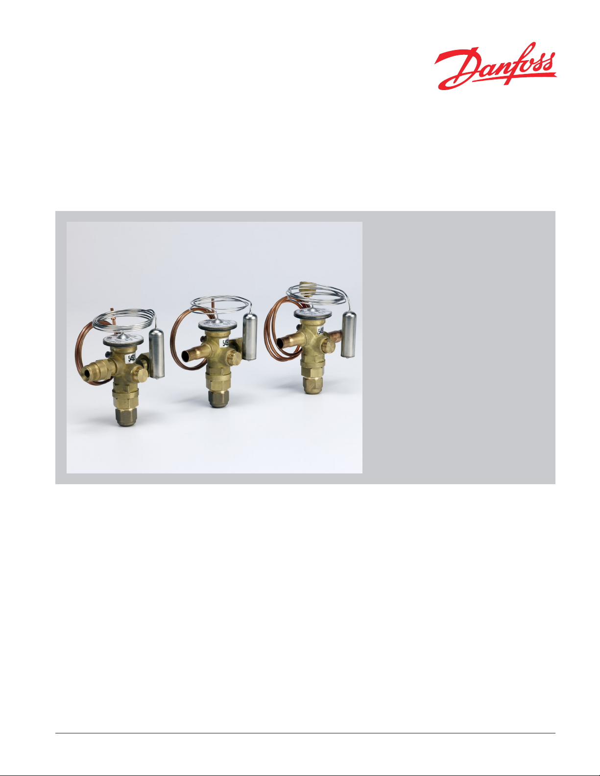
Thermostatic Expansion Valves
Type TR 6
Introduction
The TR 6 series is a hermetic tight design,
designed and developed with features
especially for use in applications such as:
y Residential air conditioning systems
y Split systems
y Roof top units
y Heat pumps
y Light commercial air conditioning systems
y Chillers
Features y Compact size - hermetic design
y Refrigerants & rated capacities ranging up to
- R22: 6.7 TR / 23.6 kW
- R410A: 7 TR / 24.5 kW
- Others on request
y Laser-welded power element
- Longer diaphragm life.
- High pressure tolerance and working
pressure.
y Stainless steel capillary tube
- Tolerates more bending for easier installation
and longer life.
- High strength and vibration resistance.
y Stainless steel bulb
- Self-aligning for fast and easy installation;
secures with a single bulb strap/OEM strap
- More contact surface for better heat transfer
The TR design incorporates a hot-pressed
brass body with the entire power element,
including the capillary tube and bulb,
fabricated from stainless steel. All valves are
designed with balanced port which reduces
the inuence from varying condensing
pressures. The valves can be delivered with
special connections and ttings both at the
inlet and outlet and at the equalizer connection.
y Balance port design
y A complete program with internal check valve
with low pressure drop at full ow or without
internal check valve.
y Adjustable or non-adjustable superheat, for
customer specic factory setting.
y Bleed function available.
y Customer specic engravement.
y Solder and mechanical connections
y Straightway versions with xed orice and
with external equalization.
y UL listed, le SA7200
DKRCC.PD.AN0.A6.22 / 520H7258
Data sheet Thermostatic expansion valves , type TR 6
Valve program
Standard versions
Options on request
Technical data
Refrigerants:
R22 and R410A
Operating range:
+14 °F to +59 °F / –10 °C to +15 °C
Setting:
Fixed setting:
Static superheat in accordance with
customers' specications.
Adjustable setting:
Factory static superheat of 7.2 °F / 4 °K.
Refrigerants:
Other refrigerants.
Range:
Other temperature ranges.
MOP:
Special MOP charges.
Capillary tube lengths:
20 In. / 0.5 m
38.4 In / 0.975 m
Max. operating temperature
Thermostatic element:
R22: max. 212 °F / 100 °C
R410A: max. 212 °F / 100 °C
Valve body:
230 °F / 110 °C
Packing:
Single or industrial pack
Versions:
All valves are in straightway versions.
With or without internal check valve.
Standard connections:
3
/8 in. ODF inlet x 1/2 in. ODF outlet x
1
/4 In are nut 24.3 inch length
Capillary tube length: 31.5 In /0.8 m
Options for Connections:
Inlet/Outlet:
– Inlet: 3/8 in. ODM, 3/8 in. ODF, 1/2 in. ODF, chatle,
aeroquip
– Outlet: 3/8 in. ODF, 1/2 in ODF, 5/8 in ODF, chatle,
aeroquip, are
Equalizer:
Cu capillary tube size: Ø 1/8 in.
¼ in. Flare Nut with l = 9.5, 16.9 or 24.3 in.
Solder 1/8 in. ODM with l = 16.9 or 24.3 in.
Solder 1/4 in ODF with l = 31.7 or 39.1 in.
Max. working pressure
MWP 630 psig / PS = 45.5 bar
Max. test pressure
680 psig / Pf = 47 bar
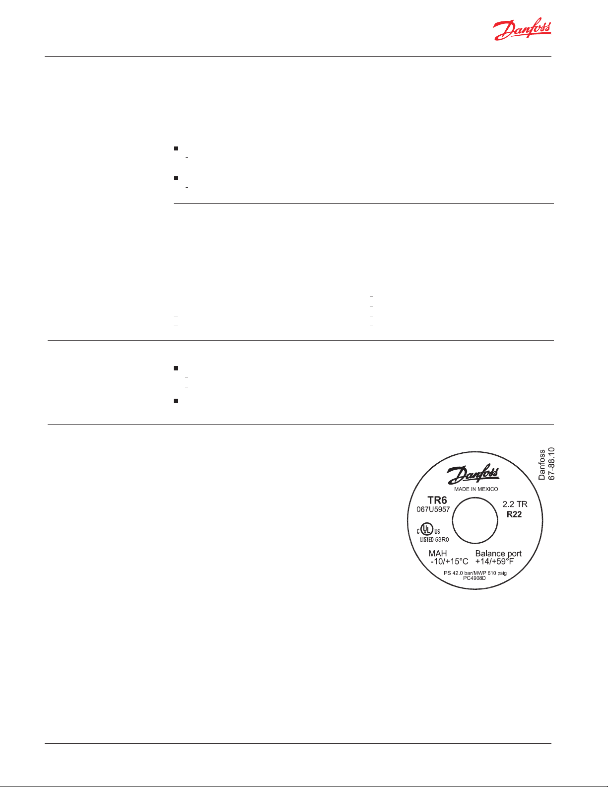
Identication
Essential valve data is given on the power element.
Main valve data example:
TR6 = Valve type
R410A = Refrigerant
6.70 TR = Rated capacity Qnom
in Tons of Refrigeration
MWP 630psig/
PS 45.5 bar = Max. working pressure in
psig and bar
067Uxxxx = Code number
BC1109D = Date making (BC=Mexico,
week 11, year 2009,
weekday D=Thursday)
+15/+60 °F = Evaporating temperature
range in °F
-10/+15 °C = Evaporating temperature
range in °C
Fig. 1
2 DKRCC.PD.AN0.A6.22 / 520H7258
Data sheet Thermostatic expansion valves , type TR 6
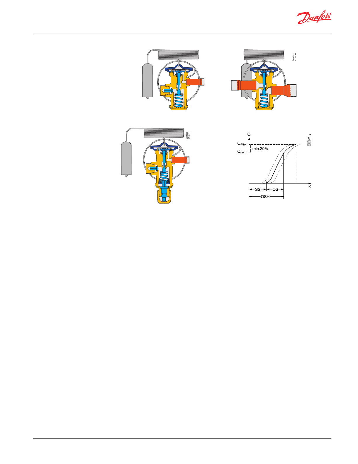
Design and function
Fig. 2 TR 6 with xed setting
1. Bulb
2. Thermostatic element
3. Push pin seal
4. Balanced port
5. Check valve
6. Setting spindle for adjustment
of static superheat (SS)
7. Equalizer
8. Inlet connection
9. Outlet connection
Fig. 3 TR 6 with adjustable setting
The central push pin is sealed with a robust seal
(pos. 3) that ensures maximum tightness and
minimum friction through the lifetime of the
valve.
The balanced port (pos. 4) ensures minimal
superheat changes when condensing pressure
varies. This feature makes the valve ideal for biow operation.
Static superheat (SS) can be adjusted with the
setting spindle (see g. 3, pos. 6) . The standard
superheat setting is 3.6 ° F / 2 °K.
Fig. 4
Terminology (g.4)
SS = Static superheat
OS = Opening superheat
OSH = SS + OS = Operating superheat
Example
Static superheat
SS = 3.6°F (2K) (factory setting)
or according to customer specication.
Opening superheat
OS = 7.2 °F (4K)
The opening superheat is 7.2 °F / 3.6 °C, i.e. from
the point the valve begins to open up to nominal
capacity. Opening superheat (OS) is a xed value
and cannot be changed.
Operating superheat
OSH = SS + OS
OSH = 3.6 °F + 7.2 °F = 10.8 °F (6 °K)
OSH is the total superheat that can be measured
on the system.
DKRCC.PD.AN0.A6.22 / 520H7258 3

Data sheet Thermostatic expansion valves , type TR 6
Application
TR 6
without
check valve
EVR/EVRH
Fig. 5. Traditional air conditioning system, cooling only
4-way
Indoor coil
valve
SGI/SGN/SGH
DCL/DML
Outdoor coil
TR 6
with check
valve
SGI/SGN/SGH
Fig. 6. Traditional air conditioning / heat pump system
Indoor coil Outdoor coil
TR 6
without
check valve
Fig. 7. Simplied air conditioning / heat pump system (bi-ow)
Fig. 5 illustrates the diagram of a traditional air
conditioning system where the TR 6 is controlling
liquid injection in one direction only.
Fig. 6 illustrates a split air conditioning/heat
pump system with cooling/heating mode and
two thermostatic expansion valves, one for
cooling mode and one for heating mode.
The thermostatic expansion valves each has a
built-in check valve, which has the function of
preventing ow in one direction and allowing the
ow in the opposite direction.
It means that one thermostatic expansion valve
is controlling liquid injection into the evaporator
DCB/DMB
4-way
valve
has an open check valve allowing the liquid
refrigerant ow in the liquid line.
Fig. 7 illustrates a similar system as the previous
one, but this time it is a packed unit with a
short distance between the evaporator and
the condenser, the bi-ow feature of the TR 6
thermostatic expansion valve can be used.
The two thermostatic expansion valves have,
therefore, been replaced by one TR 6 bi-ow valve
controlling liquid injection in both directions.
The normal ow direction marked with an arrow
should be used for the primary function, i.e.
cooling or heating.
and the other thermostatic expansion valve
TR 6
with check
valve
4 DKRCC.PD.AN0.A6.22 / 520H7258

Data sheet Thermostatic expansion valves , type TR 6
Ordering
Adjustable setting
Check valve capacity
Range N = 14 °F → 59 °F (–10 °C → +15 °C)
Rated capacity
1)
Q
Refrigerant
TR kW
3.3 11.4 3 067L5855
4.5 15.8 4 067L5856
R22
5.3 18.5 5 067L5857
5.6 19.6 6 067L5858
6.7 23.6 7 067L5859
3 10.5 3 067L5955
4 14.0 4 067L5956
R410A
5 17.5 5 067L5957
6 21.0 6 067L5958
7 24.5 7 067L5959
Pressure equalisation = ¼ in. ODF
1
) The rated capacity is based on: Evaporating temperature, t
Condensing temperature, t
2
) Partnumbers consist of a valve, bulbstrap and the following connectors:
1 Chatle
1 Aeroquip
3
8
/
" female connector
5
8
/
" female connector
= 90 °F / 32 °C, Opening superheat, OS = max. 7.2 °F / 4K
c
TC=90 °F/ 32 °C TI=75 °F/ 24 °C
nom
= 41 °F / 5 °C, Liquid temperature, tl = 82 °F / 28 °C,
e
Orice no.
R22 and R410A
Connection
3
/8 in. x 1/2 in. x 1/4 in. equalizer
with are nut ODF
Inlet × Outlet
2)
Mass ow lb/h
Dp (psi)
Fig. 8 Internal check valve for orice bypass in reverse ow (ow rate as a function of pressure dierential)
DKRCC.PD.AN0.A6.22 / 520H7258 5

Data sheet Thermostatic expansion valves , type TR 6
Capacity
US units
SI units
Capacity in TR for MAH +14/+59 °F at 7.2 °F static superheat SS
Type
TR 6
TR 6
Orice
no.
Evaporating temperature 0°F Evaporating temperature 20°F
3 1.48 1.63 1.72 1.77 1.80 1.81 1.81 1.79 1.99 2.21 2.32 2.39 2.42 2.43 2.41 2.39
4 2.17 2.38 2.50 2.56 2.59 2.59 2.57 2.53 2.88 3.17 3.31 3.39 3.41 3.41 3.38 3.33
5 2.67 2.91 3.05 3.11 3.14 3.13 3.10 3.05 3.49 3.83 3.99 4.07 4.10 4.08 4.03 3.97
6 2.85 3.11 3.24 3.30 3.32 3.30 3.26 3.21 3.72 4.07 4.24 4.32 4.33 4.31 4.25 4.18
7 3.49 3.79 3.93 3.98 3.98 3.94 3.87 3.79 4.55 4.95 5.14 5.21 5.21 5.16 5.08 4.97
Evaporating temperature 40°F Evaporating temperature 50°F
3 2.61 3.01 3.27 3.36 3.35 3.32 3.28 3.22 2.56 2.96 3.24 3.41 3.54 3.63 3.69 3.72
4 3.78 4.36 4.51 4.55 4.54 4.49 4.43 4.34 3.70 4.28 4.68 4.94 5.12 5.24 5.12 4.99
5 4.55 5.13 5.28 5.33 5.33 5.27 5.19 5.09 4.45 5.16 5.64 5.95 6.14 6.02 5.89 5.75
6 4.91 5.42 5.59 5.64 5.63 5.56 5.47 5.36 4.81 5.57 6.09 6.42 6.45 6.33 6.20 6.05
7 6.00 6.53 6.73 6.79 6.76 6.67 6.55 6.40 6.07 7.03 7.68 7.81 7.72 7.58 7.42 7.23
Pressure drop across valve D psi Pressure drop across valve D psi
50 75 100 125 150 175 200 225 50 75 100 125 150 175 200 225
Capacity in kW for MAH –10 °C/+15 °C at 4 °K static superheat SS
Type
TR 6
TR 6
Orice
no.
Evaporating temperature –17.8°C Evaporating temperature –6.7°C
3 5.18 5.71 6.03 6.21 6.31 6.34 6.32 6.27 6.98 7.72 8.13 8.36 8.47 8.49 8.45 8.36
4 7.61 8.34 8.74 8.96 9.05 9.05 8.98 8.87 10.08 11.08 11.60 11.86 11.95 11.92 11.82 11.65
5 9.34 10.20 10.67 10.90 10.98 10.95 10.85 10.69 12.22 13.39 13.98 14.26 14.34 14.28 14.12 13.89
6 9.98 10.87 11.34 11.56 11.62 11.56 11.42 11.23 13.03 14.25 14.85 15.11 15.17 15.08 14.89 14.62
7 12.23 13.25 13.75 13.94 13.93 13.79 13.55 13.25 15.92 17.34 18.00 18.25 18.25 18.06 17.77 17.39
Evaporating temperature 4.4°C Evaporating temperature 10°C
3 9.14 10.55 11.44 11.75 11.73 11.63 11.47 11.27 8.95 10.36 11.33 11.95 12.39 12.71 12.91 13.03
4 13.22 15.27 15.78 15.92 15.89 15.73 15.50 15.20 12.95 14.99 16.39 17.28 17.92 18.35 17.91 17.45
5 15.93 17.94 18.49 18.67 18.64 18.46 18.18 17.82 15.59 18.05 19.74 20.81 21.49 21.07 20.63 20.14
6 17.19 18.97 19.55 19.73 19.69 19.47 19.15 18.76 16.84 19.49 21.31 22.46 22.58 22.16 21.70 21.17
7 21.00 22.85 23.57 23.77 23.67 23.36 22.93 22.41 21.25 24.60 26.89 27.33 27.02 26.54 25.96 25.31
Pressure drop across valve D bar Pressure drop across valve D bar
3.5 5.2 6.9 8.6 10.3 12.1 13.8 15.5 3.5 5.2 6.9 8.6 10.3 12.1 13.8 15.5
R22
R22
Correction for subcooling Dt
The evaporator capacity used must be
sub
corrected if subcooling deviates from 7.2°F/ 4°K.
The corrected capacity can be obtained by
multiplying the evaporator capacity by the
correction factor given below.
Correction factor for subcooling Dt
Correction factor
R22 1.00 1.06 1.11 1.15 1.20 1.24 1.29 1.33
4 °K 10 °K 15 °K 20 °K 25 °K 30 °K 35 °K 40 °K
7.2 °F 18 °F 27 °F 36 °F 45 °F 55 °F 63 °F 72 °F
sub
6 DKRCC.PD.AN0.A6.22 / 520H7258
Note:
Insucient subcooling can produce ash gas.
Dt
sub

Data sheet Thermostatic expansion valves , type TR 6
Capacity (cont.)
US units
SI units
Capacity in TR for MAH +14/+59°F at 7.2°F static superheat SS
Type
TR 6
TR 6
Orice
no.
Evaporating temperature 0°F Evaporating temperature 20°F
3 1.48 1.67 1.79 1.86 1.90 1.93 1.94 1.94 1.87 2.13 2.30 2.40 2.46 2.50 2.51 2.51
4 2.20 2.47 2.63 2.72 2.78 2.81 2.81 2.80 2.74 3.12 3.36 3.49 3.56 3.60 3.61 3.59
5 2.71 3.05 3.23 3.34 3.41 3.43 3.43 3.41 3.36 3.82 4.10 4.25 4.33 4.37 4.37 4.35
6 2.91 3.25 3.45 3.56 3.62 3.65 3.64 3.61 3.59 4.08 4.37 4.53 4.61 4.65 4.64 4.61
7 3.58 3.99 4.22 4.34 4.40 4.41 4.39 4.34 4.42 5.00 5.34 5.52 5.61 5.64 5.62 5.56
Evaporating temperature 40°F Evaporating temperature 50°F
3 2.30 2,63 2.86 3.01 3.09 3.14 3.15 3.15 2.53 2.90 3.15 3.32 3.43 3.48 3.49 3.48
4 3.33 3.80 4.11 4.31 4.41 4.46 4.47 4.44 3.63 4.15 4.49 4.71 4.85 4.90 4.90 4.87
5 4.03 4.59 4.96 5.20 5.31 5.36 5.36 5.32 4.36 4.97 5.37 5.63 5.79 5.84 5.84 5.80
6 4.31 4.90 5.29 5.54 5.65 5.70 5.69 5.65 4.66 5.31 5.73 6.00 6.16 6.21 6.21 6.16
7 5.29 6.01 6.47 6.77 6.89 6.93 6.91 6.85 5.73 6.51 7.02 7.34 7.53 7.57 7.55 7.48
Pressure drop across valve D psi Pressure drop across valve D psi
50 75 100 125 150 175 200 225 50 75 100 125 150 175 200 225
Capacity in kW for MAH –10 °C/+15 °C at 4 °K static superheat SS
Type
TR 6
TR 6
Orice
no.
Evaporating temperature –17.8°C Evaporating temperature –6.7°C
3 5.19 5.86 6.25 6.50 6.66 6.76 6.79 6.79 6.53 7.47 8.06 8.40 8.62 8.74 8.79 8.78
4 7.69 8.65 9.19 9.53 9.73 9.83 9.85 9.80 9.60 10.93 11.75 12.20 12.47 12.60 12.63 12.57
5 9.50 10.66 11.31 11.70 11.92 12.02 12.02 11.95 11.76 13.37 14.34 14.87 15.16 15.30 15.31 15.22
6 10.17 11.39 12.07 12.47 12.68 12.77 12.74 12.65 12.58 14.28 15.30 15.84 16.13 16.26 16.24 16.13
7 12.53 13.98 14.76 15.19 15.40 15.44 15.36 15.20 15.46 17.51 18.70 19.32 19.63 19.73 19.66 19.47
Evaporating temperature 4.4°C Evaporating temperature 10°C
3 8.04 9.22 10.01 10.55 10.82 10.98 11.03 11.01 8.86 10.16 11.03 11.62 12.01 12.17 12.22 12.19
4 11.64 13.30 14.38 15.10 15.44 15.61 15.63 15.55 12.71 14.52 15.70 16.48 16.97 17.14 17.16 17.05
5 14.10 16.07 17.35 18.19 18.57 18.75 18.75 18.63 15.26 17.40 18.79 19.70 20.25 20.44 20.43 20.29
6 15.07 17.16 18.51 19.38 19.77 19.94 19.92 19.77 16.31 18.58 20.05 20.99 21.57 21.74 21.72 21.55
7 18.52 21.05 22.66 23.68 24.11 24.27 24.20 23.98 20.05 22.80 24.56 25.68 26.34 26.51 26.44 26.19
Pressure drop across valve D bar Pressure drop across valve D bar
3.5 5.2 6.9 8.6 10.3 12.1 13.8 15.5 3.5 5.2 6.9 8.6 10.3 12.1 13.8 15.5
R410A
R410A
Correction for subcooling Dt
The evaporator capacity used must be
sub
Note:
Insucient subcooling can produce ash gas.
corrected if subcooling deviates from 7.2 °F/ 4 °K.
The corrected capacity can be obtained by
multiplying the evaporator capacity by the
correction factor given below.
Correction factor for subcooling Dt
Correction factor
R410A 1.00 1.08 1.14 1.20 1.26 1.31 1.37 1.43
4 °K 10 °K 15 °K 20 °K 25 °K 30 °K 35 °K 40 °K
7.2 °F 18 °F 27 °F 36 °F 45 °F 55 °F 63 °F 72 °F
sub
Dt
sub
DKRCC.PD.AN0.A6.22 / 520H7258 7

Data sheet Thermostatic expansion valves , type TR 6
Sizing
t
l
pe~t
e
EVR/EVRH
Fig. 9
Q
e
SGI/SGN/SGH
DCL/DML
p
c
t
c
US units
Example:
Refrigerant R22
The corrected evaporator capacity then becomes
4.0 × 1.06 = 4.24 TR
Evaporating temperature te = 40°F
pe = 79 psi
Condensing temperature tc = 118°F
pc = 256 psi
Pressure drop in liquid line,
As the selected valve must be equal to or slightly
larger than the corrected evaporator capacity
of 4.24 TR, the TR 6 with orice 4 having a table
capacity of 5.4 TR would be a suitable choice.
drier and distributor system Dp2+ Dp1 = 27 psi
Pressure drop in valve
Dp = 256 – 79 – 27 = 150 psi
Subcooling Dt
= tc – tl = 18 °F
sub
Evaporator capacity = 4.0 TR
Correction factor from table = 1.06
Capacity in TR for MAH +14/+59°F at 7.2°F static superheat SS
Type
TR 6
TR 6
Orice
no.
Evaporating temperature 0°F Evaporating temperature 20°F
3 1.48 1.63 1.72 1.77 1.80 1.81 1.81 1.79 1.99 2.21 2.32 2.39 2.42 2.43 2.41 2.39
4 2.17 2.38 2.50 2.56 2.59 2.59 2.57 2.53 2.88 3.17 3.31 3.39 3.41 3.41 3.38 3.33
5 2.67 2.91 3.05 3.11 3.14 3.13 3.10 3.05 3.49 3.83 3.99 4.07 4.10 4.08 4.03 3.97
6 2.85 3.11 3.24 3.30 3.32 3.30 3.26 3.21 3.72 4.07 4.24 4.32 4.33 4.31 4.25 4.18
7 3.49 3.79 3.93 3.98 3.98 3.94 3.87 3.79 4.55 4.95 5.14 5.21 5.21 5.16 5.08 4.97
Evaporating temperature 40°F Evaporating temperature 50°F
3 2.61 3.01 3.27 3.36 3.35 3.32 3.28 3.22 2.56 2.96 3.24 3.41 3.54 3.63 3.69 3.72
4 3.78 4.36 4.51 4.55 4.54 4.49 4.43 4.34 3.70 4.28 4.68 4.94 5.12 5.24 5.12 4.99
5 4.55 5.13 5.28 5.33 5.33 5.27 5.19 5.09 4.45 5.16 5.64 5.95 6.14 6.02 5.89 5.75
6 4.91 5.42 5.59 5.64 5.63 5.56 5.47 5.36 4.81 5.57 6.09 6.42 6.45 6.33 6.20 6.05
7 6.00 6.53 6.73 6.79 6.76 6.67 6.55 6.40 6.07 7.03 7.68 7.81 7.72 7.58 7.42 7.23
Pressure drop across valve D psi Pressure drop across valve D psi
50 75 100 125 150 175 200 225 50 75 100 125 150 175 200 225
R22
8 DKRCC.PD.AN0.A6.22 / 520H7258

Data sheet Thermostatic expansion valves , type TR 6
Dimensions and weights
Fixed setting
Adjustable setting
All dimensions in inches
Fig. 10
All dimensions in inches
Fig. 11
Weight
0.57 lbs
Weight
0.67 lbs
9 DKRCC.PD.AN0.A6.22 / 520H7258 © Danfoss A/S (AC-MCI sw) 2012-12
 Loading...