

Page 1
Data sheet
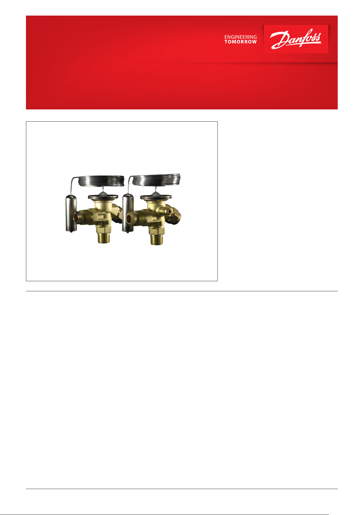
Thermostatic expansion valves
Type T2 / TE2
Thermostatic expansion valves regulate the
injection of refrigerant liquid into evaporators.
Injection is controlled by the refrigerant
superheat.
Therefore the valves are especially suitable
for liquid injection in ”dry“ evaporators where
the superheat at the evaporator outlet is
proportional to the evaporator load.
Features
y Large temperature range
– Equally applicable to freezing, refrigeration
and air conditioning applications.
y Interchangeable orice assembly
– easy storage
– easy capacity matching
– better service.
– easy cleaning and replacement of lter
y Rated capacities from 1 to 20.5 kW /
0.3 to 5.8 TR for R407C
y Can be supplied with MOP (Max. Operating
Pressure).
– Protects the compressor motor against
excessive evaporating pressure during
normal operation
y Stainless steel bulb and Danfoss patented
bulb strap
– Fast and easy to install
– Good temperature transfer from pipe to
bulb
y Valves for special temperature ranges can be
supplied
y Design protected
© Danfoss | DCS (rm) | 2019.07
DKRCC.PD.AA0.3A.02 | 1
Page 2
Data sheet | Thermostatic expansion valves, type T2 / TE2
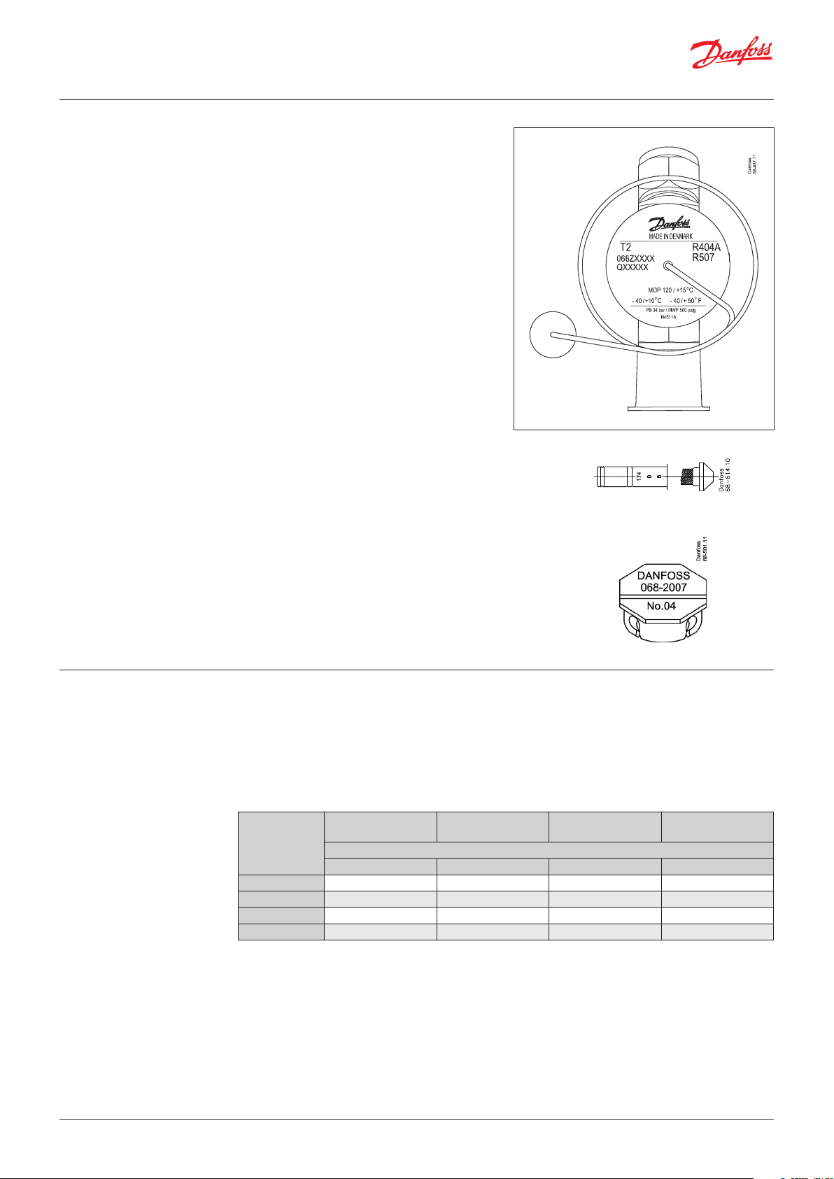
Identication The thermostatic element has laser engraved
data on top of the diaphragm. This engraving
gives valve type (with code number), evaporating
temperature range, MOP point, refrigerant, and
max. working pressure. PS/MWP.
T2 = internal equalization
TE2 = external equalization
Production place and date
N4511A =
N = Nordborg, Denmark
(BE = Wuqing, China)
45 = week
11 = 2011
A = Monday
Orice assembly for T2 and TE2
The orice assembly is marked with the orice
size (e.g. 06) and week stamp + last number in
the year (e.g. 174).
The orice assembly number is also given on the
lid of its plastic container.
Capillary tube label for T2 and TE2
The label gives the orice size (04) and consists
of the lid of the orice assembly plastic container.
It can easily be fastened around the expansion
valve capillary tube to clearly identify the valve
size.
Technical data Max. temperature
Bulb, when valve is installed: 100 °C
Bulb, element not mounted: 60 °C
Min. temperature
T2 – TE2: -60 °C
MOP-points
Refrigerant
R22 100 psig / 6.9 bar (abs) 60 psig / 4.0 bar (abs) 35 psig / 2.4 bar (abs) 20 psig / 1.4 bar (abs)
R407C 95 psig / 6.6 bar (abs) – – –
R134a 55 psig / 3.8 bar (abs) 30 psig / 2.0 bar (abs) 15 psig / 1.0 bar (abs) –
R404A/R507 120 psig / 8.3 bar (abs) 75 psig / 5.2 bar (abs) 50 psig / 3.4 bar (abs) 30 psig / 2.1 bar (abs)
1
) Pe in bar gauge
Orice assembly and lter for are x are version
for T2 and TE2
Capillary tube label
T2 and TE2
Max. test pressure
PT = 38 bar
Max. working pressure
PS/MWP = 34 bar
Range N
-40 °C – 10 °C
MOP-point in evaporating temperature te and evaporating pressure p
15 °C / 60 °F 0 °C / 32 °F -10 °C / 15 °F -20 °C / -4 °F
Range NM
-40 °C – -5 °C
Range NL
-40 °C – -15 °C
Range B
-60 °C – -25 °C
1
)
e
Superheat Standard superheat setting SS is 4K for all
SS = static superheat
OS = opening superheat
SH = SS + OS = total superheat
Q
= rated capacity
nom
Q
= maximum capacity
max
Static superheat SS can be adjusted with setting
spindle.
standard valves.
The opening superheat OS is 6 K from when
opening begins to where the valve gives its rated
capacity Q
nom.
Example
Static superheat SS = 5 K
Opening superheat OS = 6 K
Total superheat SH = 5 + 6 = 11 K
© Danfoss | DCS (rm) | 2019.07
DKRCC.PD.AA0.3A.02 | 2
Page 3
Data sheet | Thermostatic expansion valves, type T2 / TE2
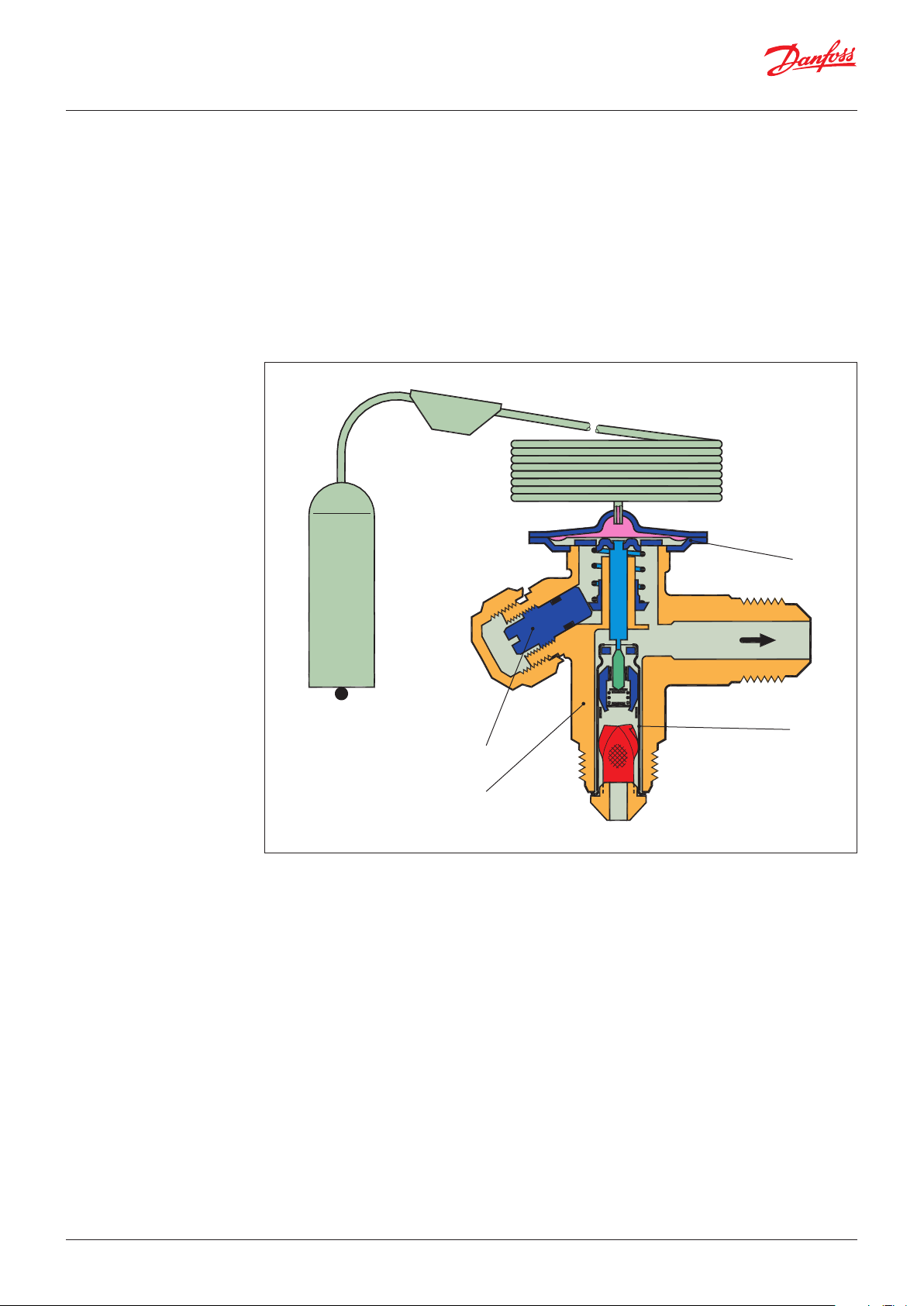
Design Function General
T2 and TE2 valves have an interchangeable orice
assembly.
The orice assembly is suitable for all versions of
valve body and refrigerants and in all evaporating
temperature ranges.
The charge in the thermostatic element depends
on the refrigerant and evaporating temperature
range.
The valves are available with internal (T2) or
external (TE2) pressure equalization.
External pressure equalization should always be
used on systems with liquid distributors.
The bulb gives fast and precise reaction to
temperature changes in the
evaporator. The bulb is xed with a Danfoss
patented bulb strap for quick, easy and reliable
connection. The valves are able to withstand
the eects that normally occur with hot gas
defrosting.
To ensure long operating life, the valve cone and
seat are made of a special alloy with particularly
good wear qualities.
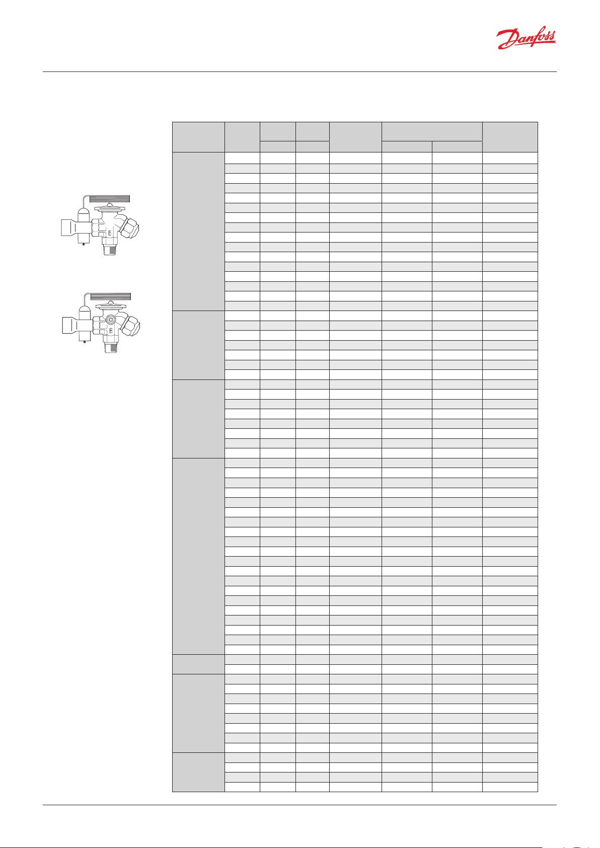
Danfoss
68Z05.14.20
1
1. Thermostatic element (diaphragm)
2. Interchangeable orifice assembly
3. Valve body
4. Superheat setting spindle (see
instructions)
2
4
3
T2
© Danfoss | DCS (rm) | 2019.07
DKRCC.PD.AA0.3A.02 | 3
Page 4
Data sheet | Thermostatic expansion valves, type T2 / TE2
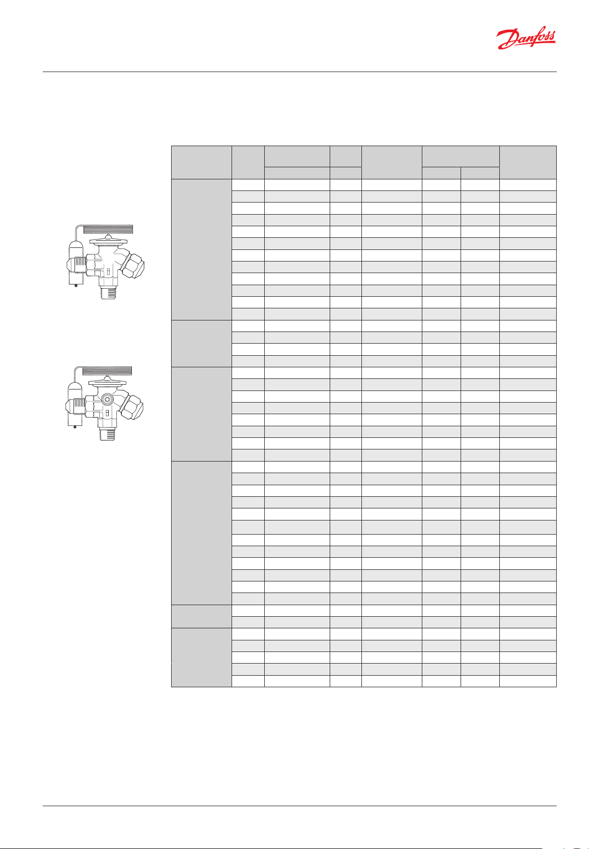
Technical data and ordering
T2/TE2 Thermostatic element with bulb strap
Flare x are
Refrigerant Typ e
T2 -40 – 10 – –
T2 -40 – 10 15 –
T2 -40 – -5 0 –
T2 -40 – -15 -10 –
T2 -60 – -25 – –
R22/R407C 1)
T2 -60 – -25 -20 –
TE2 -40 – 10 – ¼ in / 6mm
TE2 -40 – 10 15 ¼ in / 6mm
TE2 -40 – -5 0 ¼ in / 6mm
TE2 -40 – -15 -10 ¼ in / 6mm
TE2 -60 – -25 – ¼ in / 6mm
TE2 -60 – -25 -20 ¼ in / 6mm
T2 -40 – 10 – –
R407C
T2 -40 – 10 15 –
TE2 -40 – 10 – ¼ in / 6mm
TE2 -40 – 10 15 ¼ in / 6mm
T2 -40 – 10 – –
T2 -40 – 10 15 –
T2 -40 – -5 0 –
R134a /R513 A
T2 -40 – -15 -10 –
TE2 -40 – 10 – ¼ in / 6mm
TE2 -40 – 10 15 ¼ in / 6mm
TE2 -40 – -5 0 ¼ in / 6mm
TE2 -40 – -15 -10 ¼ in / 6mm
T2 -40 – 10 – –
T2 -40 – 10 15 –
T2 -40 – -5 0 –
T2 -40 – -15 -10 –
T2 -60 – -25 – –
R404A/R507
T2
TE2 -40 – 10 – ¼ in / 6mm
TE2 -40 – 10 15 ¼ in / 6mm
TE2 -40 – -5 0 ¼ in / 6mm
TE2 -40 – -15 -10 ¼ in / 6mm
TE2 -60 – -25 – ¼ in / 6mm
TE2 -60 – -25 -20 ¼ in / 6mm
R407F/R40 7A
T2 -40 – 10 – –
TE2 -40 – 10 – ¼ in / 6mm
T2 -40 – 10 – –
TE2 -40 – 10 – ¼ in / 6mm
R448A/R449A
T2 -40 – -15 -10 –
T2 -60 – -25 -20 –
TE2 -60 – -25 -20 ¼ in / 6mm
1
) For R407C plants. Please select valves from the dedicated R407C program
Range MOP
equlization
[°C] [°C] [in.] [mm]
-60 – -25 -20 –
Pressure
Flare
Capillary tube: 1.5 m
Range N = -40 – 10 °C
Range B = -60 – -25 °C
Range NM = -40 – -5 °C MOP 0 °C
Range NL = -40 – -15 °C MOP -10 °C
Connection are
inlet × outlet
3
/8 × 1/210×12 068Z3206
3
/8 × 1/210×12 068Z3208
3
/8 × 1/210×12 068Z3224
3
/8 × 1/210×12 068Z3226
3
/8 × 1/210×12 068Z3207
3
/8 × 1/210×12 068Z3228
3
/8 × 1/210×12 068Z3209
3
/8 × 1/210×12 068Z3211
3
/8 × 1/210×12 068Z3225
3
/8 × 1/210×12 068Z3227
3
/8 × 1/210×12 068Z3210
3
/8 × 1/210×12 068Z3229
3
/8 × 1/210×12 068Z3496
3
/8 × 1/210×12 068Z3516
3
/8 × 1/210×12 068Z3501
3
/8 × 1/210×12 068Z3517
3
/8 × 1/210×12 068Z3346
3
/8 × 1/210×12 068Z3347
3
/8 × 1/210×12 068Z3393
3
/8 × 1/210×12 068Z3369
3
/8 × 1/210×12 068Z3348
3
/8 × 1/210×12 068Z3349
3
/8 × 1/210×12 068Z3392
3
/8 × 1/210×12 068Z3370
3
/8 × 1/210×12 068Z3400
3
/8 × 1/210×12 068Z3402
3
/8 × 1/210×12 068Z3406
3
/8 × 1/210×12 068Z3408
3
/8 × 1/210×12 068Z3401
3
/8 × 1/210×12 068Z3410
3
/8 × 1/210×12 068Z3403
3
/8 × 1/210×12 068Z3405
3
/8 × 1/210×12 068Z3407
3
/8 × 1/210×12 068Z3409
3
/8 × 1/210×12 068Z3404
3
/8 × 1/210×12 068Z3411
3
/8 × 1/210×12 068Z3715
3
/8 × 1/210×12 068Z3714
3
2
/8 × 1/
3
/8 × 1/210×12 068Z3728
3
/8 × 1/210×12 068Z3675
3
/8 × 1/210×12 068Z3735
3
/8 × 1/210×12 068Z3736
– 068Z3727
Code no.
Multi pack
© Danfoss | DCS (rm) | 2019.07
DKRCC.PD.AA0.3A.02 | 4
Page 5
Data sheet | Thermostatic expansion valves, type T2 / TE2
Technical data and ordering
T2/TE2 Thermostatic element with bulb strap
Flare x solder
Refrigerant Type
Range MOP
[°C] [°C]
-40 – 10 – –
T2
T2 -40 – 10 – – – 10×12 068Z3302
T2 -40 – 10 15 –
T2 -40 – 10 15 – – 10×12 068Z3308
T2 -40 – -15 -10 – – 10×12 068Z3366
T2 -60 – -25 – –
T2 -60 – -25 – – – 10×12 068Z3361
R22/R407C 1)
T2 -60 – -25 -20 –
TE2 -40 – 10 – ¼ in.
TE2 -40 – 10 – 6 mm – 10×12 068Z3305
TE2 -40 – 10 15 ¼ in.
TE2 -40 – 10 15 6 mm – 10×12 068Z3311
TE2 -40 – -15 -10 6 mm – 10×12 068Z3367
TE2 -60 – -25 – ¼ in.
TE2 -60 – -25 – 6 mm – 10×12 068Z3363
TE2 -60 – -25 -20 –
T2 -40 – 10 – – – 10×12 068Z3502
T2 -40 – 10 15 –
T2 -40 – 10 15 – – 10×12 068Z3514
R407C
TE2 -40 – 10 – ¼ in.
TE2 -40 – 10 – 6 mm – 10×12 068Z3503
TE2 -40 – 10 15 ¼ in.
TE2 -40 – 10 15 6 mm – 10×12 068Z3515
T2 -40 – 10 – –
T2 -40 – 10 – – – 10×12 068Z3384
T2 -40 – 10 15 –
R134a/R513A
T2 -40 – 10 15 – – 10×12 068Z3388
TE2 -40 – 10 – ¼ in.
TE2 -40 – 10 – 6 mm – 10×12 068Z3386
TE2 -40 – 10 15 ¼ in.
TE2 -40 – 10 15 6 mm – 10×12 068Z3390
T2 -40 – 10 – –
T2 -40 – 10 – – – 10×12 068Z3435
T2 -40 – 10 15 –
T2 -40 – 10 15 – – 10×12 068Z3423
T2 -40 – -15 -10 –
T2 -40 – -15 -10 – – 10×12 068Z3436
T2 -60 – -25 – –
T2 -60 – -25 – – – 10×12 068Z3425
T2 -60 – -25 -20 –
R404A/R507
T2 -60 – -25 -20 – – 10×12 068Z3427
TE2 -40 – 10 – ¼ in.
TE2 -40 – 10 – 6 mm – 10×12 068Z3422
TE2 -40 – 10 15 6 mm – 10×12 068Z3424
TE2 -40 – 10 15 ¼ in.
TE2 -40 – -15 -10 ¼ in.
TE2 -40 – -15 -10 6 mm – 10×12 068Z3437
TE2 -60 – -25 – ¼ in.
TE2 -60 – -25 – 6 mm – 10×12 068Z3426
TE2 -60 – -25 -20 ¼ in.
TE2 -60 – -25 -20 6 mm – 10×12 068Z3428
R407F/R407A
T2 -40 – 10 – –
TE2 -40 – 10 – ¼ in.
T2 -40 – 10 – –
TE2 -40 – 10 – ¼ in.
T2 -40 – -15 -10 –
R448A/R449A
T2 -60 – -25 -20 –
TE2 -40 – -15 -10 ¼ in.
TE2 -60 – -25 -20 ¼ in.
T2 -40 – -15 -10 – – 10×12 068Z3674
TE2 -60 – -25 -20 6 mm – 10×12 068Z3672
T2 -40 – 10 – –
R452A
1
) For R407C plants, please select valves from the dedicated R407C program
TE2 -40 – 10 – ¼ in
T2 -40 – 10 – – – 10×12 068Z3808
TE2 -40 – 10 – 6 mm – 10×12 068Z3809
Pressure
equalization
solder
Capillary tube: 1.5 m
Range N = -40 – 10 °C
Range NL = -40 – -15 °C
Range B = -60 – -25 °C
Connection
inlet (Flare) × outlet (Solder)
[in.] [mm]
3
2
/8 × 1/
3
/8 × 1/
3
/8 × 1/
3
/8 × 1/
3
/8 × 1/
3
/8 × 1/
3
/8 × 1/
3
/8 × 1/
3
/8 × 1/
3
/8 × 1/
3
/8 × 1/
3
/8 × 1/
3
/8 × 1/
3
/8 × 1/
3
/8 × 1/
3
/8 × 1/
3
/8 × 1/
3
/8 × 1/
3
/8 × 1/
3
/8 × 1/
3
/8 × 1/
3
/8 × 1/
3
/8 × 1/
3
/8 × 1/
3
/8 × 1/
3
/8 × 1/
3
/8 × 1/
3
/8 × 1/
3
/8 × 1/
3
/8 × 1/
3
/8 × 1/
3
/8 × 1/
3
/8 × 1/
3
/8 × 1/
3
/8 × 1/
2
2
2
2
2
2
2
2
2
2
2
2
2
2
2
2
2
2
2
2
2
2
2
2
2
2
2
2
2
2
2
2
2
2
– 068Z3281
– 068Z3287
– 068Z3357
– 068Z3319
– 068Z3284
– 068Z3290
– 068Z3359
– 068Z3320
– 068Z3329
1
/2 in. 068Z3446
– 068Z3447
– 068Z3383
– 068Z3387
– 068Z3385
– 068Z3389
– 068Z3414
– 068Z3416
– 068Z3429
– 068Z3418
– 068Z3420
– 068Z3415
– 068Z3417
– 068Z3430
– 068Z3419
– 068Z3421
– 068Z3716
– 068Z3713
– 068Z3729
– 068Z3730
– 068Z3664
– 068Z3737
– 068Z3665
– 068Z3738
– 068Z3806
– 068Z3807
Code no.
Multi pack
© Danfoss | DCS (rm) | 2019.07
DKRCC.PD.AA0.3A.02 | 5
Page 6
Danfoss
68Z62.11
Data sheet | Thermostatic expansion valves, type T2 / TE2
Flare connections
The rated capacity is based on:
Evaporating temperature te = 40 °F
Condensing temperature tc = 100 °F
Refrigerant temperature ahead
of valve tl = 98 °F
Connection for copper tubing
with outside diameter
Reducer for copper tubing
with outside diameter
[in.] [mm] [in.] [mm]
1
4
/
3
8
/
1
2
/
– –
6 – – 011L1101
10 – – 011L1135
12 – – 011L1103
1
4
/
6 011L1107
Example :
A TE2 thermostatic expansion valve consists of
two elements + are nuts if required:
– 1 thermostatic element
– 1 orice assembly and are nuts
When ordering one thermostatic expansion valve,
TE2 with orice 01, ve code numbers are required:
– 1-o thermostatic element 068Z3209
– 1-o orice assembly 01 068-2010
– 1-o 3⁄8 in. are nut 011L1135
– 1-o 1⁄2 in. are nut 011L1103
– 1-o 1⁄4 in. are nut 011L1101
Range N: -40 to 50 °F
Rated capacity in tons (TR)
Orice no.
R22 R407C R134a R513A
0X 0.25 0.26 0.19 0.16 0.18 0.25 0.28 0.26 0.25
00 0.51 0.51 0.34 0.29 0.37 0.49 0.56 0.51 0.49
01 1.0 1.0 0.59 0.51 0.75 1.0 1.1 1.0 0.97
02 1.3 1.4 0.73 0.62 1.0 1.3 1.5 1.4 1.3
03 2.3 2.3 1.2 1.0 1.8 2.3 2.6 2.3 2.3
04 3.4 3.5 1.8 1.5 2.8 3.5 4.1 3.6 3.5
05 4.8 4.7 2.4 2.0 3.7 4.6 5.4 4.6 4.5
06 5.6 5.6 2.9 2.5 4.4 5.6 6.5 5.7 5.5
R404A
R507
R407A R407F R448A R449A
Code no.
The rated capacity is based on:
Evaporating temperature te = 4.4 °C
Condensing temperature tc = 38 °C
Refrigerant temperature ahead
of valve tl = 37 °C
1 2
1. Orice assembly with lter
2. Orice assembly with lter for
solder adaptor
Range N: -40 to 10 °C
Rated capacity in kW
Orice no.
R22 R407C R134a R513A
R404A
R507
R407A R407F R448A R449A
0X 0.90 0.92 0.68 0.58 0.64 0.88 1.0 0.90 0.88
00 1.8 1.8 1.2 1.0 1.3 1.7 2.0 1.8 1.7
01 3.5 3.5 2.1 1.8 2.6 3.4 3.9 3.5 3.4
02 4.7 4.8 2.6 2.2 3.7 4.7 5.4 4.8 4.6
03 8.0 8.1 4.3 3.7 6.3 8.0 9.2 8.1 7.9
04 12.1 12.4 6.4 5.4 9.9 12.4 14.3 12.6 12.1
05 16.7 16.5 8.4 6.9 13.0 16.3 19.0 16.3 15.7
06 19.7 19.7 10.1 8.6 15.5 19.6 22.9 19.8 19.1
Orice assembly with lter
Orice no. Code no.
0X 068-2002
00 068-2003
01 068-2010
02 068-2015
03 068-2006
04 068-2007
05 068-2008
06 068-2009
Orice assembly with lter for solder adaptor
Orice no. Code no.
0X 068-2089
00 068-2090
01 068-2091
02 068-2092
03 068-2093
04 068-2094
05 068-2095
06 068-2096
Filter
Filter type Code no. Multi pack
For flare connection 068-0003
For solder adaptor 068-0015
© Danfoss | DCS (rm) | 2019.07
The adaptor is for use with thermostatic expansion
valves T2 and TE2. When the adaptor is fitted
correctly it meets the sealing requirements of
DIN 8964. The flare orifice in T2 and TE2 can be
used with a solder adaptor when the orifice filter
is replaced with a specific filter intended for solder
adaptors.
Only in this way the sealing requirements of
DIN 8964 can be fulfilled. Solder adaptors for filter
driers (FSA) must not be used on the T2 inlet.
DKRCC.PD.AA0.3A.02 | 6
Page 7

Data sheet | Thermostatic expansion valves, type T2 / TE2
Solder adaptor
Bulb strap (Danfoss patented)
The adaptor is for use with thermostatic
expansion valves T2 and TE2 with
are × solder connections. When the adaptor is
tted correctly it meets the sealing requirements
of DIN 8964.
The adaptor oers the following advantages:
The orice assembly can be replaced.
The lter can be cleaned or replaced.
Solder adaptor without orice assembly and lter
Connection ODF solder Code no.
1
⁄4 in. 068-2062
6 mm 068-2063
3
⁄8 in. 068-2060
10 mm 068-2061
When using the solder adapter, a special orice
assembly is required. Please use the following
tables to select both the appropriate adapter and
orice asembly.
Only in this way can the sealing requirements of
DIN 8964 be fullled.
Solder adaptor for lter drier (FSA) may not be
used in the T2 inlet.
Filter for solder adaptor
Description Code no.
Filter excl. orifice assembly 068-0015
Each valve is delivered with a Danfoss patented
bulb strap. Spares can be ordered.
Description Pack mode Quantity / pack Code no.
Bulb strap 0.4 mm Max. 28 mm tube I 45 068U3505
Bulb strap 0.4 mm Max. 50 mm tube I 45 068U3506
Bulb strap 0.4 mm Max. 28 mm tube M 25 068U3507
Bulb strap 0.4 mm Max. 50 mm tube M 25 068U3508
How to select a valve
Example:
Refrigerant = R407C
Q (capacity) = 1.1kW
cond
T
(condensing temperature) = 25 °C
T
(evaporator temperature) = -30 °C
evap
sub
T
(subcooling temperature) = 2 K
Dpd (distributer pressure drop) = 1 bar
Q (capacity) = 1.1kW
sub
f
(subcooling correction factor) = 0.98
fp (distribution correction factor) = 0.96
Q
sub
f
x f
= Selected capacity
p
1.1
0.98 x 0.96
= 1.17 kW
The selection will be:
TE2 orice 00 (1.21 kW > 1.17 kW)
Capacity in kW, range N -40 °C to 10 °C. Opening superheat sh= 6 K
Valve type Orice no.
T2 / TE2 0X
T2 / TE2 00 0.99 1. 21 1.42 1.60
T2 / TE2 01 1.41 1.8 0 2.27 2.77
Cond. temp.
[°C]
25
-40 -30 -20 -10
0.76 0.83 0.88 0.90
Evaporating [°C]
Subcooling correction factor 'fsub'
Subcooling [K] 2 4 10 15
Correction factor 0.98 1.00 1.07 1.12
Distributer correction factor 'fp' *)
Pressure drop
[bar]
“Pressure
drop
[bar]”
*) calculated at 32 °C condensing temperature
0 1 1 1 1
1 0.96 0.96 0.96 0.96
1.5 0.94 0.94 0.94 0.94
2 0.92 0.92 0.92 0.92
-40 -35 -30 -25
Evaporating temp. [°C]
© Danfoss | DCS (rm) | 2019.07
DKRCC.PD.AA0.3A.02 | 7
Page 8

Data sheet | Thermostatic expansion valves, type T2 / TE2
Capacity
Capacity in kW, range N -40 °C to 10 °C. Opening superheat sh= 6 K R22
Valve type Orice no.
T2 / TE2 0X
T2 / TE2 00 0.95 1.18 1. 39 1.53 1.55 1.37
T2 / TE2 01 1.32 1.72 2 .18 2.63 2.91 2.78
T2 / TE2 02 1.49 1.98 2.57 3. 24 3.82 3.88
T2 / TE2 03 2.49 3.32 4.32 5.43 6.40 6.57
T2 / TE2 04 3.59 4.79 6. 35 8.16 9.72 9.88
T2 / TE2 05 4.69 6.25 8.30 10.8 0 13.10 13 .50
T2 / TE2 06 5.53 7. 3 6 9.73 12.70 15. 40 16 .00
Valve type Orice no.
T2 / TE2 0X
T2 / TE2 00 0.99 1.23 1.47 1.67 1.77 1. 72
T2 / TE2 01 1.37 1.80 2.31 2.86 3.33 3.50
T2 / TE2 02 1.56 2.08 2. 74 3.54 4.38 4.92
T2 / TE2 03 2.62 3.51 4.62 5.96 7. 39 8.35
T2 / TE2 04 3.85 5 .12 6.83 8.98 11. 20 12 .70
T2 / TE2 05 5.03 6.68 8.93 11.9 0 15.30 17. 50
T2 / TE2 06 5.89 7. 82 10.40 13.9 0 17.90 20.70
Cond. temp.
[°C]
25
Cond. temp.
[°C]
35
-40 -30 -20 -10 0 10
0.75 0.82 0.86 0.86 0 .81 0.68
-40 -30 -20 -10 0 10
0.78 0.86 0.91 0.93 0.92 0.85
Evaporating [°C]
Capacity [kW]
Evaporating [°C]
Capacity [kW]
Evaporating [°C]
Valve type Orice no.
T2 / TE2 0X
T2 / TE2 00 1.01 1.26 1. 52 1.75 1.9 0 1.94
T2 / TE2 01 1.41 1.85 2.39 3.00 3.59 3.96
T2 / TE2 02 1.61 2.14 2.84 3.72 4 .74 5.60
T2 / TE2 03 2.71 3.64 4.82 6.32 8.08 9.63
T2 / TE2 04 4.06 5.37 7.14 9.47 12 . 20 14.50
T2 / TE2 05 5.30 7. 01 9. 37 12.60 16.70 20.30
T2 / TE2 06 6 .19 8.18 10 .9 0 14.70 19. 50 24.0 0
Valve type Orice no.
T2 / TE2 0X
T2 / TE2 00 1.01 1.26 1. 53 1.77 1.95 2.04
T2 / TE2 01 1.42 1. 87 2.42 3.06 3.71 4.19
T2 / TE2 02 1.63 2.18 2.89 3. 81 4.92 5.95
T2 / TE2 03 2.76 3.70 4.93 6.51 8.46 10.30
T2 / TE2 04 4.23 5.53 7. 32 9.68 12. 50 15 . 30
T2 / TE2 05 5.52 7. 24 9.64 13. 00 17. 30 21.70
T2 / TE2 06 6.42 8.43 11. 20 15 .10 20.30 25.80
Cond. temp.
[°C]
45
Cond. temp.
[°C]
55
-40 -30 -20 -10 0 10
Capacity [kW]
0.80 0.88 0.94 0.97 0.98 0.95
Evaporating [°C]
-40 -30 -20 -10 0 10
Capacity [kW]
0.79 0.88 0.94 0.98 1.00 0.99
Subcooling correction factor 'fsub'
Subcooling [K] 2 4 10 15 20 25 30 35 40 45 50
Correction factor 0.98 1.00 1.05 1.10 1.14 1.19 1.23 1.28 1.32 1.36 1.41
Distributer correction factor 'fp' *)
Pressure drop
[bar]
“Pressure
drop
[bar]”
*) calculated at 32 °C condensing temperature
-40 -35 -30 -25 -20 -15 -10 -5 0 5 10 15
0 1 1 1 1 1 1 1 1 1 1 1 1
1 0.96 0.95 0.95 0.95 0.95 0.95 0.94 0.94 0.93 0.92 0.91 0.89
1.5 0.93 0.93 0.93 0.93 0.92 0.92 0.91 0.91 0.90 0.88 0.86 0.82
2 0.91 0.91 0.90 0.90 0.90 0.89 0.88 0.87 0.86 0.84 0.81 0.76
Evaporating temp. [°C]
© Danfoss | DCS (rm) | 2019.07
DKRCC.PD.AA0.3A.02 | 8
Page 9

Data sheet | Thermostatic expansion valves, type T2 / TE2
Capacity
Capacity in kW, range B -60 °C to -25 °C. Opening superheat sh= 6 K R22
Valve type Orice no.
T2 / TE2 0X
T2 / TE2 00 0.55 0.77 1.03 1.28
T2 / TE2 01 0.72 1.06 1.47 1.95
T2 / TE2 02 0.80 1.17 1.6 6 2.26
T2 / TE2 03 1.32 1.94 2.76 3.77
T2 / TE2 04 1.87 2.76 3.95 5.45
T2 / TE2 05 2.45 3.60 5.15 7.14
T2 / TE2 06 2.91 4.26 6.10 8.50
Valve type Orice no.
T2 / TE2 0X
T2 / TE2 00 0.56 0.79 1.06 1.3 4
T2 / TE2 01 0.74 1.0 8 1.52 2.04
T2 / TE2 02 0.82 1. 20 1.72 2.36
T2 / TE2 03 1.35 1.99 2.85 3.93
T2 / TE2 04 1.90 2.81 4.04 5.63
T2 / TE2 05 2.50 3.66 5.26 7.36
T2 / TE2 06 2.96 4.33 6.21 8.71
Cond. temp.
[°C]
25
Cond. temp.
[°C]
35
-60 -50 -40 -30
0.54 0.67 0.78 0.84
-60 -50 -40 -30
0.56 0.69 0.80 0.88
Evaporating [°C]
Capacity [kW]
Evaporating [°C]
Capacity [kW]
Evaporating [°C]
Valve type Orice no.
T2 / TE2 0X
T2 / TE2 00 0.57 0.80 1.0 8 1.37
T2 / TE2 01 0.75 1.10 1. 55 2.09
T2 / TE2 02 0.82 1. 22 1. 74 2.41
T2 / TE2 03 1.36 2.01 2.88 4.00
T2 / TE2 04 1.91 2.82 4.06 5.70
T2 / TE2 05 2.52 3.68 5.29 7. 42
T2 / TE2 06 2.98 4.35 6.23 8.75
Valve type Orice no.
T2 / TE2 0X
T2 / TE2 00 0.57 0.80 1.0 8 1.38
T2 / TE2 01 0.75 1.10 1. 55 2.10
T2 / TE2 02 0.82 1. 21 1.74 2 .41
T2 / TE2 03 1.36 2.00 2.87 4.01
T2 / TE2 04 1.89 2.79 4.03 5.66
T2 / TE2 05 2.52 3.67 5.25 7.3 7
T2 / TE2 06 2.98 4.32 6.17 8.66
Cond. temp.
[°C]
45
Cond. temp.
[°C]
55
-60 -50 -40 -30
Capacity [kW]
0.56 0.70 0.82 0.91
Evaporating [°C]
-60 -50 -40 -30
Capacity [kW]
0.56 0.70 0.82 0.91
Subcooling correction factor 'fsub'
Subcooling [K] 2 4 10 15 20 25 30 35 40 45 50
Correction factor 0.98 1.00 1.07 1.12 1.18 1.23 1.28 1.34 1.39 1.45 1.50
Distributer correction factor 'fp' *)
Pressure drop
[bar]
“Pressure
drop
[bar]”
*) calculated at 32 °C condensing temperature
-40 -35 -30 -25 -20 -15 -10 -5 0 5 10 15
0 1 1 1 1 1 1 1 1 1 1 1 1
1 0.96 0.96 0.96 0.96 0.96 0.96 0.95 0.95 0.95 0.94 0.93 0.92
1.5 0.94 0.94 0.94 0.94 0.94 0.93 0.93 0.93 0.92 0.91 0.90 0.88
2 0.92 0.92 0.92 0.92 0.91 0.91 0.91 0.90 0.89 0.88 0.86 0.84
Evaporating temp. [°C]
© Danfoss | DCS (rm) | 2019.07
DKRCC.PD.AA0.3A.02 | 9
Page 10

Data sheet | Thermostatic expansion valves, type T2 / TE2
Capacity
Capacity in kW, range N -40 °C to 10 °C. Opening superheat sh= 6 K R407C
Valve type Orice no.
T2 / TE2 0X
T2 / TE2 00 0.99 1. 21 1.42 1. 60 1.69 1.63
T2 / TE2 01 1.41 1. 80 2.27 2.77 3.19 3. 31
T2 / TE2 02 1.59 2.06 2.67 3.40 4.18 4.64
T2 / TE2 03 2.65 3.44 4.46 5.73 7. 07 7. 85
T2 / TE2 04 3.86 4.98 6.4 4 8.35 10.6 0 12 .50
T2 / TE2 05 5.04 6.52 8.46 11 . 00 14.0 0 16 .30
T2 / TE2 06 5.94 7.71 10.10 13.20 16. 80 19. 40
Valve type Orice no.
T2 / TE2 0X
T2 / TE2 00 0.99 1.22 1.45 1. 67 1.81 1. 85
T2 / TE2 01 1.40 1.81 2. 32 2.88 3.43 3.76
T2 / TE2 02 1.59 2.08 2.72 3.54 4.48 5.28
T2 / TE2 03 2.66 3.48 4.57 5.98 7. 62 8.98
T2 / TE2 04 3.93 5.10 6.65 8 .74 11.4 0 14.20
T2 / TE2 05 5.13 6.66 8.73 11. 50 15.10 18.60
T2 / TE2 06 6. 01 7.85 10.4 0 13 . 8 0 18.10 22.20
Cond. temp.
[°C]
25
Cond. temp.
[°C]
35
-40 -30 -20 -10 0 10
0.76 0.83 0.88 0.90 0.88 0. 81
-40 -30 -20 -10 0 10
0.76 0.84 0.90 0.94 0.95 0.92
Evaporating [°C]
Capacity [kW]
Evaporating [°C]
Capacity [kW]
Evaporating [°C]
Valve type Orice no.
T2 / TE2 0X
T2 / TE2 00 0.95 1.19 1.43 1.67 1.85 1.94
T2 / TE2 01 1.36 1.77 2.28 2.88 3.50 3.97
T2 / TE2 02 1.55 2.04 2.69 3.54 4.58 5.58
T2 / TE2 03 2.60 3.42 4.53 6. 01 7.82 9.52
T2 / TE2 04 3.89 5.07 6.66 8.83 11. 70 15.00
T2 / TE2 05 5.06 6.62 8.73 11. 70 15 .60 19 . 80
T2 / TE2 06 5.90 7.76 10.30 13 .90 18 .70 23.60
Valve type Orice no.
T2 / TE2 0X
T2 / TE2 00 0.89 1.12 1. 37 1. 61 1.81 1.93
T2 / TE2 01 1. 27 1.67 2.18 2.78 3.43 3.96
T2 / TE2 02 1.4 6 1.93 2.57 3.42 4.49 5.58
T2 / TE2 03 2.46 3.27 4.36 5.84 7. 71 9.60
T2 / TE2 04 3.74 4.90 6.48 8.65 11. 60 15 .10
T2 / TE2 05 4.85 6.39 8.49 11. 4 0 15 .40 20.00
T2 / TE2 06 5.61 7.45 9.99 13.60 18. 50 24.0 0
Cond. temp.
[°C]
45
Cond. temp.
[°C]
55
-40 -30 -20 -10 0 10
Capacity [kW]
0.73 0.82 0.89 0.94 0.97 0.97
Evaporating [°C]
-40 -30 -20 -10 0 10
Capacity [kW]
0.68 0.77 0.85 0.91 0.95 0.96
Subcooling correction factor 'fsub'
Subcooling [K] 2 4 10 15 20 25 30 35 40 45 50
Correction factor 0.98 1.00 1.07 1.12 1.18 1.23 1.28 1.34 1.39 1.45 1.50
Distributer correction factor 'fp' *)
Pressure drop
[bar]
“Pressure
drop
[bar]”
*) calculated at 32 °C condensing temperature
-40 -35 -30 -25 -20 -15 -10 -5 0 5 10 15
0 1 1 1 1 1 1 1 1 1 1 1 1
1 0.96 0.96 0.96 0.96 0.96 0.96 0.95 0.95 0.95 0.94 0.93 0.92
1.5 0.94 0.94 0.94 0.94 0.94 0.93 0.93 0.93 0.92 0.91 0.90 0.88
2 0.92 0.92 0.92 0.92 0.91 0.91 0.91 0.90 0.89 0.88 0.86 0.84
Evaporating temp. [°C]
© Danfoss | DCS (rm) | 2019.07
DKRCC.PD.AA0.3A.02 | 10
Page 11

Data sheet | Thermostatic expansion valves, type T2 / TE2
Capacity
Capacity in kW, range N -40 °C to 10 °C. Opening superheat sh= 6 K R134a
Valve type Orice no.
T2 / TE2 0X
T2 / TE2 00 0.52 0.67 0.82 0.95 1.03 0.98
T2 / TE2 01 0.70 0.92 1.19 1.48 1.72 1.77
T2 / TE2 02 0.78 1.03 1.35 1.73 2.08 2.24
T2 / TE2 03 1.31 1.72 2.27 2.89 3.49 3.76
T2 / TE2 04 1.89 2.49 3.28 4.21 5.15 5.69
T2 / TE2 05 2.50 3.28 4.33 5.57 6.80 7.4 8
T2 / TE2 06 2.98 3.93 5.20 6.69 8 .16 8.96
Valve type Orice no.
T2 / TE2 0X
T2 / TE2 00 0.54 0.69 0.86 1.03 1.17 1. 22
T2 / TE2 01 0.72 0.96 1.25 1.6 0 1.95 2.20
T2 / TE2 02 0.81 1.07 1.43 1. 87 2.36 2.79
T2 / TE2 03 1.36 1. 80 2.40 3.14 3.96 4.69
T2 / TE2 04 2.02 2.64 3.51 4.60 5.85 7. 07
T2 / TE2 05 2.66 3.48 4.62 6.06 7.72 9.31
T2 / TE2 06 3 .15 4 .14 5.51 7. 24 9.24 11.10
Valve type Orice no.
T2 / TE2 0X
T2 / TE2 00 0.54 0.70 0.88 1.07 1.25 1.36
T2 / TE2 01 0.73 0.97 1.28 1.66 2.08 2.46
T2 / TE2 02 0.82 1.09 1.46 1.93 2. 51 3 .11
T2 / TE2 03 1.38 1. 83 2.45 3.25 4.22 5.24
T2 / TE2 04 2.10 2.73 3.63 4.80 6.24 7. 8 9
T2 / TE2 05 2.76 3.59 4.76 6. 31 8.23 10.40
T2 / TE2 06 3.25 4.24 5.64 7.51 9. 82 12. 4 0
Cond. temp.
[°C]
25
Cond. temp.
[°C]
35
Cond. temp.
[°C]
45
-40 -30 -20 -10 0 10
0.48 0.54 0.59 0.62 0. 61 0.54
-40 -30 -20 -10 0 10
0.49 0.57 0.63 0.67 0.69 0.66
-40 -30 -20 -10 0 10
0.49 0.57 0.64 0.69 0.73 0.74
Evaporating [°C]
Capacity [kW]
Evaporating [°C]
Capacity [kW]
Evaporating [°C]
Capacity [kW]
Valve type Orice no.
T2 / TE2 0X
T2 / TE2 00 0.53 0.69 0. 87 1.07 1.27 1. 43
T2 / TE2 01 0.72 0.95 1. 26 1.65 2 .11 2.57
T2 / TE2 02 0.81 1.08 1.45 1.94 2.55 3.24
T2 / TE2 03 1.38 1. 82 2.44 3. 27 4.30 5.50
T2 / TE2 04 2.14 2.77 3.66 4.85 6.38 8.25
T2 / TE2 05 2.81 3.63 4.80 6 .37 8.40 10.90
T2 / TE2 06 3.30 4.26 5.65 7. 54 10 .00 13 .00
Cond. temp.
[°C]
55
-40 -30 -20 -10 0 10
0.47 0.56 0.63 0.69 0. 74 0.76
Evaporating [°C]
Capacity [kW]
Subcooling correction factor 'fsub'
Subcooling [K] 2 4 10 15 20 25 30 35 40 45 50
Correction factor 0.98 1.00 1.07 1.12 1.18 1.23 1.29 1.34 1.40 1.45 1.50
Distributer correction factor 'fp' *)
Pressure drop
[bar]
“Pressure
drop
[bar]”
*) calculated at 32 °C condensing temperature
-40 -35 -30 -25 -20 -15 -10 -5 0 5 10 15
0 1 1 1 1 1 1 1 1 1 1 1 1
1 0.93 0.93 0.93 0.93 0.92 0.92 0.92 0.91 0.90 0.89 0.87 0.83
1.5 0.90 0.89 0.89 0.89 0.88 0.88 0.87 0.86 0.84 0.82 0.79 0.74
2 0.86 0.86 0.85 0.85 0.84 0.83 0.82 0.81 0.79 0.76 0.71 0.62
Evaporating temp. [°C]
© Danfoss | DCS (rm) | 2019.07
DKRCC.PD.AA0.3A.02 | 11
Page 12

Data sheet | Thermostatic expansion valves, type T2 / TE2
Capacity
Capacity in kW, range N -40 °C to 10 °C. Opening superheat sh= 6 K R404A
Valve type Orice no.
T2 / TE2 0X
T2 / TE2 00 0.72 0.92 1.09 1.21 1. 22 1.08
T2 / TE2 01 1.00 1.38 1. 81 2.20 2.40 2.25
T2 / TE2 02 1.12 1. 58 2 .17 2.79 3.25 3.22
T2 / TE2 03 1.86 2.65 3.65 4.72 5.49 5.42
T2 / TE2 04 2.68 3.83 5.36 7.12 8.53 8.69
T2 / TE2 05 3.51 5.04 7. 06 9.38 11. 20 11. 3 0
T2 / TE2 06 4 .15 5.99 8.43 11. 2 0 13.40 13 . 30
Valve type Orice no.
T2 / TE2 0X
T2 / TE2 00 0.67 0.88 1.08 1.2 5 1. 34 1.29
T2 / TE2 01 0.95 1. 33 1.79 2.28 2.64 2.70
T2 / TE2 02 1.07 1.53 2 .15 2.90 3.59 3.89
T2 / TE2 03 1.78 2.57 3.64 4.93 6.11 6.57
T2 / TE2 04 2.60 3.75 5. 37 7.45 9.53 10. 60
T2 / TE2 05 3.40 4.93 7. 07 9.82 12 .50 13.70
T2 / TE2 06 4.00 5.83 8.40 11 . 7 0 14 .9 0 16.3 0
Valve type Orice no.
T2 / TE2 0X
T2 / TE2 00 0.61 0.81 1.01 1.20 1.34 1. 38
T2 / TE2 01 0.86 1.22 1.68 2 .19 2.66 2.87
T2 / TE2 02 0.97 1.41 2.02 2.81 3.64 4.16
T2 / TE2 03 1.63 2.38 3.43 4.80 6.23 7. 06
T2 / TE2 04 2.43 3.50 5.08 7. 2 6 9 .74 11 . 4 0
T2 / TE2 05 3.17 4.60 6.69 9.58 12.9 0 14.9 0
T2 / TE2 06 3.71 5.41 7.92 11. 4 0 15 .40 17. 70
Cond. temp.
[°C]
25
Cond. temp.
[°C]
35
Cond. temp.
[°C]
45
-40 -30 -20 -10 0 10
0.55 0. 61 0.64 0.65 0.62 0.54
-40 -30 -20 -10 0 10
0.52 0. 59 0.64 0.67 0.68 0.64
-40 -30 -20 -10 0 10
0.46 0.54 0.60 0.65 0.68 0.67
Evaporating [°C]
Capacity [kW]
Evaporating [°C]
Capacity [kW]
Evaporating [°C]
Capacity [kW]
Valve type Orice no.
T2 / TE2 0X
T2 / TE2 00 0.52 0.70 0.89 1.07 1. 23 1.30
T2 / TE2 01 0 .74 1. 06 1. 47 1.96 2.44 2.73
T2 / TE2 02 0.85 1.23 1. 78 2.52 3.35 3.96
T2 / TE2 03 1.43 2.09 3.03 4.32 5.78 6.76
T2 / TE2 04 2 .17 3.10 4.50 6.51 8.98 10.90
T2 / TE2 05 2.83 4.07 5.92 8.61 11.9 0 14.4 0
T2 / TE2 06 3.29 4.77 6.99 10.3 0 14.30 17. 20
Cond. temp.
[°C]
55
-40 -30 -20 -10 0 10
0.39 0.47 0.54 0.59 0.62 0.64
Evaporating [°C]
Capacity [kW]
Subcooling correction factor 'fsub'
Subcooling [K] 2 4 10 15 20 25 30 35 40 45 50
Correction factor 0.97 1.00 1.09 1.16 1.23 1.30 1.38 1.45 1.52 1.59 1.65
Distributer correction factor 'fp' *)
Pressure drop
[bar]
“Pressure
drop
[bar]”
*) calculated at 32 °C condensing temperature
-40 -35 -30 -25 -20 -15 -10 -5 0 5 10 15
0 1 1 1 1 1 1 1 1 1 1 1 1
1 0.96 0.96 0.96 0.96 0.96 0.96 0.95 0.95 0.94 0.94 0.92 0.91
1.5 0.94 0.94 0.94 0.94 0.94 0.93 0.93 0.92 0.91 0.90 0.88 0.86
2 0.92 0.92 0.92 0.92 0.91 0.91 0.90 0.89 0.88 0.87 0.84 0.80
Evaporating temp. [°C]
© Danfoss | DCS (rm) | 2019.07
DKRCC.PD.AA0.3A.02 | 12
Page 13

Data sheet | Thermostatic expansion valves, type T2 / TE2
Capacity
Capacity in kW, range B, -60 °C to -25 °C, opening superheat sh= 6 K R404A
Valve type Orice no.
T2 / TE2 0X
T2 / TE2 00 0.50 0.65 0.83 1.02
T2 / TE2 01 0.68 0.90 1.22 1. 62
T2 / TE2 02 0.75 1.0 0 1.39 1.91
T2 / TE2 03 1.2 2 1.64 2.30 3.22
T2 / TE2 04 1.69 2.31 3.23 4.46
T2 / TE2 05 2.20 3.02 4.22 5.82
T2 / TE2 06 2.60 3.55 4.98 6.92
Valve type Orice no.
T2 / TE2 0X
T2 / TE2 00 0.47 0 . 61 0.80 1. 0 0
T2 / TE2 01 0.64 0.86 1.18 1.59
T2 / TE2 02 0.70 0.96 1.34 1.88
T2 / TE2 03 1.16 1.58 2.24 3.18
T2 / TE2 04 1.72 2.31 3.22 4.47
T2 / TE2 05 2.23 3.01 4 .19 5.83
T2 / TE2 06 2.63 3.51 4.90 6.87
Valve type Orice no.
T2 / TE2 0X
T2 / TE2 00 0.41 0. 55 0.73 0.93
T2 / TE2 01 0.56 0.77 1.08 1.4 8
T2 / TE2 02 0.63 0.86 1.23 1.76
T2 / TE2 03 1.0 4 1.44 2.07 2.99
T2 / TE2 04 1.6 8 2.20 3.04 4.23
T2 / TE2 05 2.16 2.84 3.94 5.52
T2 / TE2 06 2.57 3.30 4.57 6.46
Cond. temp.
[°C]
25
Cond. temp.
[°C]
35
Cond. temp.
[°C]
45
-60 -50 -40 -30
0.44 0. 51 0.58 0.63
-60 -50 -40 -30
0. 41 0.49 0.56 0.62
-60 -50 -40 -30
0.36 0.44 0.52 0.58
Evaporating [°C]
Capacity [kW]
Evaporating [°C]
Capacity [kW]
Evaporating [°C]
Capacity [kW]
Valve type Orice no.
T2 / TE2 0X
T2 / TE2 00 0.33 0.46 0.62 0.81
T2 / TE2 01 0.46 0.64 0.92 1.29
T2 / TE2 02 0. 51 0.73 1.06 1. 54
T2 / TE2 03 0.86 1. 22 1.80 2.65
T2 / TE2 04 1.56 1.96 2.67 3.73
T2 / TE2 05 1.98 2.50 3.44 4.85
T2 / TE2 06 2.39 2.93 3.97 5.63
Cond. temp.
[°C]
55
-60 -50 -40 -30
0.29 0.36 0.44 0.50
Evaporating [°C]
Capacity [kW]
Subcooling correction factor 'fsub'
Subcooling [K] 2 4 10 15 20 25 30 35 40 45 50
Correction factor 0.97 1.00 1.10 1.19 1.27 1.35 1.43 1.52 1.60 1.68 1.76
Distributer correction factor 'fp' *)
Pressure drop
[bar]
“Pressure
drop
[bar]”
*) calculated at 32 °C condensing temperature
0 1 1 1 1 1 1 1 1
1 0.97 0.96 0.96 0.96 0.96 0.96 0.96 0.96
1.5 0.95 0.95 0.95 0.94 0.94 0.94 0.94 0.94
2 0.93 0.93 0.93 0.93 0.92 0.92 0.92 0.92
-60 -55 -50 -45 -40 -35 -30 -25
Evaporating temp. [°C]
© Danfoss | DCS (rm) | 2019.07
DKRCC.PD.AA0.3A.02 | 13
Page 14

Data sheet | Thermostatic expansion valves, type T2 / TE2
Capacity
Capacity in kW, range N -40 °C to 10 °C. Opening superheat sh= 6 K R407F
Valve type Orice no.
T2 / TE2 0X
T2 / TE2 00 1.1 1.4 1.6 1.8 1. 8 1.7
T2 / TE2 01 1.6 2.0 2.6 3.1 3.6 3.6
T2 / TE2 02 1.8 2.3 3.0 3.9 4.8 5.1
T2 / TE2 03 2.9 3.9 5.1 6.6 8.1 8.7
T2 / TE2 04 4.3 5.6 7.4 9.6 12 . 2 14. 0
T2 / TE2 05 5.6 7.4 9.7 12 .7 16.1 18.1
T2 / TE2 06 6.6 8.7 11.6 15.2 19.3 21.5
Valve type Orice no.
T2 / TE2 0X
T2 / TE2 00 1.1 1.4 1.6 1.9 2.0 2.0
T2 / TE2 01 1.6 2 .1 2.7 3.3 3.9 4.1
T2 / TE2 02 1.8 2.4 3.1 4.1 5.2 5.9
T2 / TE2 03 3.0 4.0 5.3 7.0 8.8 10.0
T2 / TE2 04 4.4 5.8 7.7 10.2 13 .3 16 .0
T2 / TE2 05 5.8 7.6 10.1 13.5 17.5 20.9
T2 / TE2 06 6.7 9.0 12 . 0 16.1 21.0 24.8
Cond. temp.
[°C]
25
Cond. temp.
[°C]
35
-40 -30 -20 -10 0 10
0.84 0.92 0.96 0.98 0.95 0.86
-40 -30 -20 -10 0 10
0.85 0.93 0.99 1.0 1.0 0.98
Evaporating [°C]
Capacity [kW]
Evaporating [°C]
Capacity [kW]
Valve type Orice no.
T2 / TE2 0X
T2 / TE2 00 1.1 1.4 1.6 1.9 2.0 2 .1
T2 / TE2 01 1.5 2.0 2.6 3.3 4.0 4.4
T2 / TE2 02 1.8 2.3 3.1 4.1 5.3 6.3
T2 / TE2 03 3.0 4.0 5.3 7.1 9.1 10.7
T2 / TE2 04 4.4 5.9 7.8 10.4 13. 8 17.1
T2 / TE2 05 5.8 7.6 10. 2 13 .8 18 .3 22.4
T2 / TE2 06 6.7 8.9 12 .1 16.4 21.9 26.6
Valve type Orice no.
T2 / TE2 0X
T2 / TE2 00 1.0 1.3 1. 6 1.8 2.0 2.1
T2 / TE2 01 1.5 2.0 2.6 3.3 3.9 4.4
T2 / TE2 02 1.7 2.3 3.0 4.1 5.3 6.4
T2 / TE2 03 2.9 3.8 5.2 7. 0 9.1 10.9
T2 / TE2 04 4.3 5.7 7.7 10. 3 13. 8 17.4
T2 / TE2 05 5.6 7.5 10.1 13.7 18.4 22.9
T2 / TE2 06 6.5 8.7 11.9 16 .3 2 2.1 27. 4
Cond. temp.
[°C]
45
Cond. temp.
[°C]
55
-40 -30 -20 -10 0 10
0.83 0.92 0.99 1.0 1.1 1.0
-40 -30 -20 -10 0 10
0.79 0.89 0.96 1.0 1. 0 1.0
Evaporating [°C]
Capacity [kW]
Evaporating [°C]
Capacity [kW]
Subcooling correction factor 'fsub'
Subcooling [K] 1 4 10 15 20 25 30 35 40 45 50
Correction factor 0.96 1.00 1.07 1.14 1.20 1.26 1.33 1.40 1.47 1.54 1.65
Distributer correction factor 'fp' *)
Pressure drop
[bar]
“Pressure
drop
[bar]”
*) calculated at 32 °C condensing temperature
-40 -35 -30 -25 -20 -15 -10 -5 0 5 10 15
0 1 1 1 1 1 1 1 1 1 1 1 1
1 1.00 0.93 0.91 0.88 0.87 0.82 0.79 0.76 0.73 0.69 0.65 0.91
1.5 1.04 0.91 0.88 0.84 0.82 0.77 0.74 0.69 0.64 0.60 0.57 0.86
2 1.07 0.93 0.85 0.81 0.77 0.72 0.67 0.63 0.58 0.54 0.50 0.80
Evaporating temp. [°C]
© Danfoss | DCS (rm) | 2019.07
DKRCC.PD.AA0.3A.02 | 14
Page 15

Data sheet | Thermostatic expansion valves, type T2 / TE2
Capacity
Capacity in kW, range N -40 °C to 10 °C. Opening superheat sh= 6 K R407A
Valve type Orice no.
T2 / TE2 0X
T2 / TE2 00 0.97 1.2 1.4 1. 6 1.7 1.6
T2 / TE2 01 1.4 1. 8 2.3 2.8 3.2 3.2
T2 / TE2 02 1.6 2.1 2.7 3.5 4.3 4.6
T2 / TE2 03 2.6 3.4 4.6 5.9 7.3 7. 8
T2 / TE2 04 3.8 5.0 6.6 8.6 11. 0 12.6
T2 / TE2 05 5.0 6.5 8.6 11.4 14 .5 16 .4
T2 / TE2 06 5.8 7. 7 10.3 13.6 17.3 19.4
Valve type Orice no.
T2 / TE2 0X
T2 / TE2 00 0.97 1.2 1.4 1.7 1.8 1. 8
T2 / TE2 01 1.4 1. 8 2.3 2.9 3.4 3.7
T2 / TE2 02 1.6 2.1 2.8 3.6 4.6 5.3
T2 / TE2 03 2.6 3.5 4.7 6.2 7. 8 9.0
T2 / TE2 04 3.9 5.1 6.8 9.0 11. 9 14.4
T2 / TE2 05 5.0 6.7 8.9 12.0 15. 7 18.7
T2 / TE2 06 5.9 7. 9 10 .6 14.3 18. 8 22.2
Valve type Orice no.
T2 / TE2 0X
T2 / TE2 00 0.94 1. 2 1.4 1.7 1. 8 1.9
T2 / TE2 01 1.3 1. 8 2.3 2.9 3.5 3.9
T2 / TE2 02 1.5 2.0 2.7 3.7 4.7 5.6
T2 / TE2 03 2.6 3.4 4.6 6.2 8 .1 9.5
T2 / TE2 04 3.8 5.1 6.8 9.2 12 . 2 15. 2
T2 / TE2 05 5.0 6.6 8.9 12 .1 16.2 19.9
T2 / TE2 06 5.8 7. 8 10.6 14. 5 19.4 23.7
Cond. temp.
[°C]
25
Cond. temp.
[°C]
35
Cond. temp.
[°C]
45
-40 -30 -20 -10 0 10
0.74 0.81 0.86 0.87 0.85 0.77
-40 -30 -20 -10 0 10
0.74 0.82 0.88 0.91 0.91 0.88
-40 -30 -20 -10 0 10
0.72 0.80 0.87 0.91 0.93 0.92
Evaporating [°C]
Capacity [kW]
Evaporating [°C]
Capacity [kW]
Evaporating [°C]
Capacity [kW]
Valve type Orice no.
T2 / TE2 0X
T2 / TE2 00 0.88 1.1 1.4 1.6 1.8 1.9
T2 / TE2 01 1.3 1.7 2.2 2.8 3.5 3.9
T2 / TE2 02 1.4 1.9 2.6 3.5 4.6 5.6
T2 / TE2 03 2.4 3.3 4.5 6.1 8.0 9.6
T2 / TE2 04 3.7 4.9 6.6 9.0 12.1 15.4
T2 / TE2 05 4.8 6.4 8.7 11 . 9 16.1 20.3
T2 / TE2 06 5.5 7. 5 10.3 14. 2 19.4 24.2
Cond. temp.
[°C]
55
-40 -30 -20 -10 0 10
0.67 0.76 0.83 0.88 0.91 0.92
Evaporating [°C]
Capacity [kW]
Subcooling correction factor 'fsub'
Subcooling [K] 1 4 10 15 20 25 30 35 40 45 50
Correction factor 0.96 1.00 1.08 1.14 1.21 1.28 1.35 1.42 1.50 1.57 1.65
Distributer correction factor 'fp' *)
Pressure drop
[bar]
“Pressure
drop
[bar]”
*) calculated at 32 °C condensing temperature
-40 -35 -30 -25 -20 -15 -10 -5 0 5 10 15
0 1 1 1 1 1 1 1 1 1 1 1 1
1 0.97 0.93 0.92 0.89 0.86 0.83 0.80 0.78 0.74 0.72 0.67 0.91
1.5 1.01 0.92 0.88 0.85 0.81 0.78 0.73 0.71 0.67 0.63 0.59 0.86
2 1.01 0.90 0.86 0.82 0.77 0.74 0.69 0.63 0.59 0.56 0.52 0.80
Evaporating temp. [°C]
© Danfoss | DCS (rm) | 2019.07
DKRCC.PD.AA0.3A.02 | 15
Page 16

Data sheet | Thermostatic expansion valves, type T2 / TE2
Capacity
Capacity in kW, range N -40 °C to 10 °C. Opening superheat sh= 6 K R448A
Valve type Orice no.
T2 / TE2 0X
T2 / TE2 00 1.0 5 1. 25 1.4 4 1. 60 1.67 1.59
T2 / TE2 01 1. 51 1.90 2.35 2.82 3.19 3.25
T2 / TE2 02 1.72 2.19 2.78 3.50 4.22 4.58
T2 / TE2 03 2.86 3.65 4.67 5.90 7. 14 7. 7 3
T2 / TE2 04 4 .17 5.30 6.77 8.67 10.9 12. 4
T2 / TE2 05 5.45 6.93 8.87 11. 3 14.1 15. 8
T2 / TE2 06 6.45 8.26 10. 6 13. 7 17.1 19.1
Valve type Orice no.
T2 / TE2 0X
T2 / TE2 00 1.0 5 1.26 1.4 8 1. 67 1.79 1.81
T2 / TE2 01 1. 51 1.91 2.40 2.94 3.43 3.70
T2 / TE2 02 1.72 2.21 2.84 3.64 4.54 5.23
T2 / TE2 03 2.88 3.70 4.78 6.16 7.70 8.87
T2 / TE2 04 4.24 5.42 6.99 9.08 11. 7 14.1
T2 / TE2 05 5.53 7. 08 9.15 11.9 15.2 18.1
T2 / TE2 06 6.52 8.40 10.9 14. 3 18 .5 22.0
Valve type Orice no.
T2 / TE2 0X
T2 / TE2 00 1.01 1. 23 1.4 6 1.67 1.8 3 1.90
T2 / TE2 01 1.47 1.87 2.37 2.94 3. 51 3.90
T2 / TE2 02 1.67 2.16 2. 81 3.65 4.64 5.52
T2 / TE2 03 2.82 3.64 4.75 6.20 7.91 9.41
T2 / TE2 04 4.20 5.39 6.99 9.18 12 . 0 14.9
T2 / TE2 05 5.47 7.03 9.16 12. 0 15. 7 19. 2
T2 / TE2 06 6 .41 8 .31 10.9 14. 5 19. 0 23.4
Cond. temp.
[°C]
25
Cond. temp.
[°C]
35
Cond. temp.
[°C]
45
-40 -30 -20 -10 0 10
0.77 0.83 0.87 0.88 0.86 0.79
-40 -30 -20 -10 0 10
0.77 0.84 0.89 0.92 0.93 0.90
-40 -30 -20 -10 0 10
0.75 0.82 0.88 0.93 0.95 0.94
Evaporating [°C]
Capacity [kW]
Evaporating [°C]
Capacity [kW]
Evaporating [°C]
Capacity [kW]
Valve type Orice no.
T2 / TE2 0X
T2 / TE2 00 0.95 1.17 1.39 1. 61 1.79 1. 89
T2 / TE2 01 1.38 1.77 2.26 2.84 3.44 3.90
T2 / TE2 02 1.58 2.06 2.70 3.54 4.56 5.54
T2 / TE2 03 2.68 3.49 4.59 6.04 7.82 9. 51
T2 / TE2 04 4.06 5.23 6.82 9.01 11. 9 15.1
T2 / TE2 05 5.26 6.81 8.92 11. 8 15.6 19.4
T2 / TE2 06 6 .13 8.00 10.6 14. 2 19.0 23.8
Cond. temp.
[°C]
55
-40 -30 -20 -10 0 10
0.70 0.78 0.84 0.89 0.93 0.94
Evaporating [°C]
Capacity [kW]
Subcooling correction factor 'fsub'
Subcooling [K] 2 4 10 15 20 25 30 35 40 45 50
Correction factor 0.98 1.00 1.07 1.13 1.19 1.25 1.31 1.37 1.42 1.48 1.54
Distributer correction factor 'fp' *)
Pressure drop
[bar]
“Pressure
drop
[bar]”
*) calculated at 32 °C condensing temperature
-40 -35 -30 -25 -20 -15 -10 -5 0 5 10 15
0 1 1 1 1 1 1 1 1 1 1 1 1
1 0.96 0.96 0.96 0.96 0.96 0.96 0.96 0.95 0.95 0.94 0.94 0.93
1.5 0.95 0.94 0.94 0.94 0.94 0.94 0.93 0.93 0.92 0.92 0.90 0.89
2 0.93 0.93 0.92 0.92 0.92 0.92 0.91 0.90 0.90 0.89 0.87 0.85
Evaporating temp. [°C]
© Danfoss | DCS (rm) | 2019.07
DKRCC.PD.AA0.3A.02 | 16
Page 17

Data sheet | Thermostatic expansion valves, type T2 / TE2
Capacity
Capacity in kW. range N -40 °C to 10 °C. Opening superheat sh= 6 K R449A
Valve type Orice no.
T2 / TE2 0X
T2 / TE2 00 1.0 5 1.24 1.42 1.57 1.63 1.56
T2 / TE2 01 1.53 1.90 2. 32 2.76 3.12 3 .17
T2 / TE2 02 1. 74 2 .19 2.76 3.43 4.11 4.45
T2 / TE2 03 2.91 3.66 4.63 5.79 6.95 7.52
T2 / TE2 04 4.24 5.33 6.75 8.54 10.6 12. 0
T2 / TE2 05 5.55 6.98 8.84 11. 2 13.7 15. 3
T2 / TE2 06 6.59 8.32 10.6 13. 5 16. 6 18 .5
Valve type Orice no.
T2 / TE2 0X
T2 / TE2 00 1.0 5 1. 25 1.45 1. 63 1.75 1.77
T2 / TE2 01 1.53 1.91 2.36 2.87 3.34 3.61
T2 / TE2 02 1. 74 2.20 2.81 3.56 4.40 5.07
T2 / TE2 03 2.92 3.70 4.73 6.03 7. 48 8.60
T2 / TE2 04 4.30 5.43 6.93 8.92 11.4 13 .6
T2 / TE2 05 5.61 7. 10 9.09 11 . 67 14. 8 17. 4
T2 / TE2 06 6.63 8.43 10.9 14.1 17.9 21.2
Cond. temp.
[°C]
25
Cond. temp.
[°C]
35
-40 -30 -20 -10 0 10
0.76 0.82 0.85 0.87 0.85 0.78
-40 -30 -20 -10 0 10
0.76 0.82 0.87 0.90 0.91 0.88
Evaporating [°C]
Capacity [kW]
Evaporating [°C]
Capacity [kW]
Evaporating [°C]
Valve type Orice no.
T2 / TE2 0X
T2 / TE2 00 1.01 1. 22 1.43 1. 63 1.79 1. 86
T2 / TE2 01 1.48 1.86 2.33 2.87 3.41 3.80
T2 / TE2 02 1.69 2.15 2.77 3.56 4.49 5.35
T2 / TE2 03 2.84 3.63 4.68 6.05 7. 66 9.10
T2 / TE2 04 4.23 5.37 6.91 8.99 11. 6 14.4
T2 / TE2 05 5.51 7.02 9.06 11. 8 15. 2 18. 5
T2 / TE2 06 6.49 8 .31 10. 8 14.2 18.4 22.6
Valve type Orice no.
T2 / TE2 0X
T2 / TE2 00 0.95 1.15 1. 36 1.57 1.74 1.85
T2 / TE2 01 1.39 1.76 2.22 2.76 3.34 3.80
T2 / TE2 02 1.59 2.04 2.64 3.44 4 .41 5.36
T2 / TE2 03 2.69 3.46 4.49 5.87 7.54 9.15
T2 / TE2 04 4.06 5.18 6.71 8.78 11. 5 14.5
T2 / TE2 05 5.27 6.76 8.78 11 . 5 15. 0 18.7
T2 / TE2 06 6 .17 7.96 10.4 13. 9 18.3 22.9
Cond. temp.
[°C]
45
Cond. temp.
[°C]
55
-40 -30 -20 -10 0 10
Capacity [kW]
0.74 0.81 0.87 0.91 0.93 0.93
Evaporating [°C]
-40 -30 -20 -10 0 10
Capacity [kW]
0.69 0.76 0.82 0.87 0.91 0.92
Subcooling correction factor 'fsub'
Subcooling [K] 2 4 10 15 20 25 30 35 40 45 50
Correction factor 0.98 1.00 1.07 1.13 1.19 1.25 1.31 1.37 1.43 1.49 1.55
Distributer correction factor 'fp' *)
Pressure drop
[bar]
“Pressure
drop
[bar]”
*) calculated at 32 °C condensing temperature
-40 -35 -30 -25 -20 -15 -10 -5 0 5 10 15
0 1 1 1 1 1 1 1 1 1 1 1 1
1 0.96 0.96 0.96 0.96 0.96 0.96 0.96 0.95 0.95 0.94 0.94 0.93
1.5 0.95 0.94 0.94 0.94 0.94 0.94 0.93 0.93 0.92 0.91 0.90 0.89
2 0.93 0.93 0.92 0.92 0.92 0.91 0.91 0.90 0.90 0.88 0.87 0.84
Evaporating temp. [°C]
© Danfoss | DCS (rm) | 2019.07
DKRCC.PD.AA0.3A.02 | 17
Page 18

Data sheet | Thermostatic expansion valves, type T2 / TE2
Capacity
Capacity in kW. range N -40 °C to 10 °C. Opening superheat sh= 6 K R452A
Valve type Orice no.
T2 / TE2 0X
T2 / TE2 00 0.75 0.96 1.15 1. 29 1.32 1. 22
T2 / TE2 01 1.05 1.45 1.91 2.35 2.60 2.53
T2 / TE2 02 1.17 1.6 6 2.29 2.98 3.53 3.64
T2 / TE2 03 1.94 2.78 3.85 5.04 5.97 6 .11
T2 / TE2 04 2.79 4.01 5.66 7. 6 0 9.27 9.80
T2 / TE2 05 3.66 5.28 7.45 10.0 12.2 12. 7
T2 / TE2 06 4.33 6.27 8.89 12.0 14.5 15. 0
Valve type Orice no.
T2 / TE2 0X
T2 / TE2 00 0.70 0.93 1.14 1.33 1. 44 1.41
T2 / TE2 01 0.99 1.40 1.89 2.42 2.83 2.95
T2 / TE2 02 1.12 1.61 2.27 3.08 3.86 4.26
T2 / TE2 03 1.86 2.70 3.84 5.24 6.56 7.18
T2 / TE2 04 2.72 3.94 5.67 7. 92 10.2 11. 6
T2 / TE2 05 3.56 5.17 7. 46 10.4 13.4 15.0
T2 / TE2 06 4 .19 6 .12 8.87 12.5 16.1 17.8
Cond. temp.
[°C]
25
Cond. temp.
[°C]
35
-40 -30 -20 -10 0 10
0.57 0.63 0.68 0.70 0.68 0.60
-40 -30 -20 -10 0 10
0.54 0.62 0.68 0.71 0.73 0.69
Evaporating [°C]
Capacity [kW]
Evaporating [°C]
Capacity [kW]
Valve type Orice no.
T2 / TE2 0X
T2 / TE2 00 0.64 0.85 1.07 1.28 1. 44 1. 49
T2 / TE2 01 0.91 1. 29 1.78 2.34 2.85 3.11
T2 / TE2 02 1.03 1.49 2.14 2.99 3.90 4.51
T2 / TE2 03 1.72 2.52 3.64 5 .11 6.68 7. 65
T2 / TE2 04 2.56 3.70 5.39 7.73 10.4 12. 4
T2 / TE2 05 3.35 4.86 7. 09 10. 2 13. 8 16 .2
T2 / TE2 06 3.91 5.72 8.40 12.2 16 .5 19. 2
Valve type Orice no.
T2 / TE2 0X
T2 / TE2 00 0.56 0.75 0.95 1.15 1. 32 1.42
T2 / TE2 01 0.79 1.14 1.58 2 .11 2.63 2.97
T2 / TE2 02 0.91 1.32 1.91 2.71 3.62 4.31
T2 / TE2 03 1.53 2.24 3.25 4.65 6.24 7. 35
T2 / TE2 04 2.33 3. 33 4.82 7. 00 9.70 11.9
T2 / TE2 05 3.04 4.36 6.35 9.26 12 .9 15 .7
T2 / TE2 06 3.53 5 .11 7. 50 11. 0 15.5 18.7
Cond. temp.
[°C]
45
Cond. temp.
[°C]
55
-40 -30 -20 -10 0 10
0.49 0.57 0.64 0.69 0.73 0.73
-40 -30 -20 -10 0 10
0.42 0 .51 0.58 0.63 0.67 0.69
Evaporating [°C]
Capacity [kW]
Evaporating [°C]
Capacity [kW]
Subcooling correction factor 'fsub'
Subcooling [K] 2 4 10 15 20 25 30 35 40 45 50
Correction factor 0.97 1.00 1.09 1.16 1.23 1.30 1.38 1.45 1.52 1.59 1.66
Distributer correction factor 'fp' *)
Pressure drop
[bar]
“Pressure
drop
[bar]”
*) calculated at 32 °C condensing temperature
-40 -35 -30 -25 -20 -15 -10 -5 0 5 10 15
0 1 1 1 1 1 1 1 1 1 1 1 1
1 0.96 0.96 0.96 0.96 0.96 0.96 0.96 0.95 0.95 0.94 0.94 0.92
1.5 0.95 0.95 0.94 0.94 0.94 0.94 0.93 0.93 0.92 0.91 0.90 0.88
2 0.93 0.93 0.93 0.92 0.92 0.92 0.91 0.90 0.90 0.88 0.87 0.84
Evaporating temp. [°C]
© Danfoss | DCS (rm) | 2019.07
DKRCC.PD.AA0.3A.02 | 18
Page 19

Data sheet | Thermostatic expansion valves, type T2 / TE2
Capacity
Capacity in kW, range N, -40°C to 10°C, opening superheat sh= 6 K R513A
Valve type Orice no.
T2 / TE2 0X
T2 / TE2 00 0.42 0.55 0.70 0.83 0.91 0.86
T2 / TE2 01 0. 55 0.76 1.0 1.3 1.5 1.6
T2 / TE2 02 0.62 0.85 1.1 1.5 1.8 2.0
T2 / TE2 03 1.0 1.4 1.9 2.5 3.1 3.3
T2 / TE2 04 1.5 2.1 2.8 3.6 4.5 5.0
T2 / TE2 05 1.9 2.6 3.5 4.6 5.7 6.4
T2 / TE2 06 2.4 3.2 4.4 5.7 7.1 7. 9
Valve type Orice no.
T2 / TE2 0X
T2 / TE2 00 0.41 0.56 0.72 0.88 1.0 1.1
T2 / TE2 01 0. 55 0.77 1.0 1.4 1.7 1.9
T2 / TE2 02 0.61 0.86 1. 2 1.6 2.0 2.4
T2 / TE2 03 1.0 1.4 2.0 2.6 3.4 4.1
T2 / TE2 04 1.5 2.1 2.9 3.9 5.0 6.2
T2 / TE2 05 2.0 2.7 3.7 4.9 6.4 7.8
T2 / TE2 06 2.4 3.3 4.5 6.1 7.9 9.8
Cond. temp.
[°C]
25
Cond. temp.
[°C]
35
-40 -30 -20 -10 0 10
0.39 0.46 0 .51 0.54 0.53 0.47
-40 -30 -20 -10 0 10
0.39 0.46 0.52 0.57 0.59 0.58
Evaporating [°C]
Capacity [kW]
Evaporating [°C]
Capacity [kW]
Valve type Orice no.
T2 / TE2 0X
T2 / TE2 00 0.40 0.54 0.71 0.88 1.0 1.2
T2 / TE2 01 0.54 0.75 1.0 1.4 1. 7 2.1
T2 / TE2 02 0.60 0.84 1.2 1.6 2.1 2.6
T2 / TE2 03 1.0 1.4 2.0 2.7 3.5 4.5
T2 / TE2 04 1.5 2.1 2.9 3.9 5.2 6.7
T2 / TE2 05 2.0 2.7 3.7 5.0 6.7 8.5
T2 / TE2 06 2.4 3.3 4.6 6.2 8.3 10.7
Valve type Orice no.
T2 / TE2 0X
T2 / TE2 00 0.38 0.52 0.68 0.85 1.0 1.2
T2 / TE2 01 0.51 0.72 0.99 1.3 1.7 2 .1
T2 / TE2 02 0.57 0.81 1.1 1.6 2.1 2.7
T2 / TE2 03 0.98 1. 4 1.9 2.6 3.5 4.6
T2 / TE2 04 1.5 2.1 2.9 3.9 5.2 6.8
T2 / TE2 05 1.9 2.7 3.7 5.0 6.6 8.7
T2 / TE2 06 2.3 3.2 4.5 6.1 8.2 10.8
Cond. temp.
[°C]
45
Cond. temp.
[°C]
55
-40 -30 -20 -10 0 10
0.37 0.45 0.51 0.57 0. 61 0.62
-40 -30 -20 -10 0 10
0.35 0.42 0.49 0.55 0.59 0.63
Evaporating [°C]
Capacity [kW]
Evaporating [°C]
Capacity [kW]
Subcooling correction factor 'fsub'
Subcooling [K] 2 4 10 15 20 25 30 35 40 45 50
Correction factor 0.98 1.00 1.07 1.13 1.18 1.24 1.31 1.37 1.43 1.49 1.55
Distributer correction factor 'fp' *)
Pressure drop
[bar]
“Pressure
drop
[bar]”
*) calculated at 32 °C condensing temperature
-40 -35 -30 -25 -20 -15 -10 -5 0 5 10 15
0 1.00 1.00 1.00 1.00 1.00 1.00 1.00 1.00 1.00 1.00 1.00 1.00
1 0.94 0.93 0.93 0.93 0.93 0.92 0.92 0.91 0.90 0.89 0.87 0.84
1.5 0.90 0.90 0.90 0.89 0.89 0.88 0.88 0.86 0.85 0.83 0.80 0.75
2 0.87 0.86 0.86 0.85 0.85 0.84 0.83 0.81 0.79 0.77 0.72 0.64
Evaporating temp. [°C]
© Danfoss | DCS (rm) | 2019.07
DKRCC.PD.AA0.3A.02 | 19
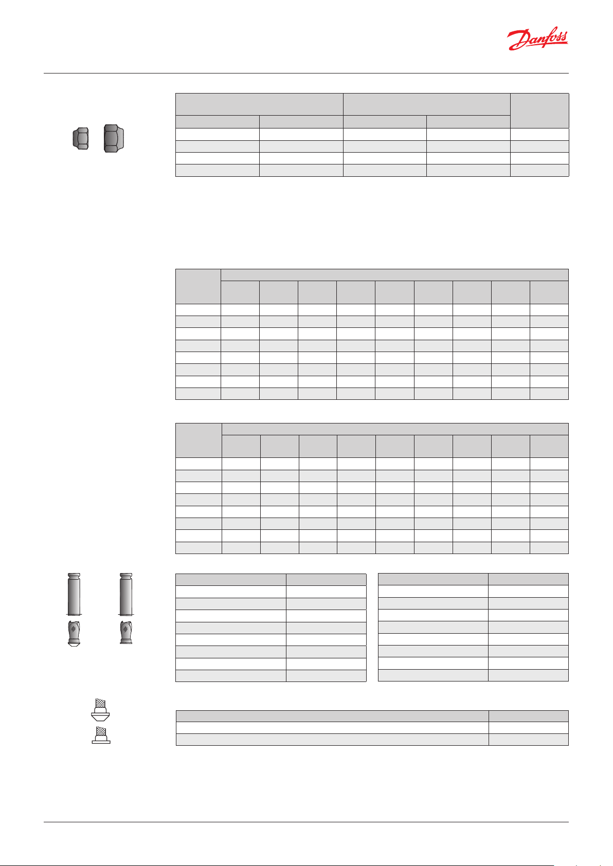
Page 20

Dimensions and weights
T2 and TE2
Flare × are
All dimentions are in mm
Flare × solder
All dimentions are in mm
Solder adaptor
Flare × are
Flare × solder
Outlet Equalization Weight
A B [kg / lb]
1
/2 ” are
1
/2 ” solder
12 mm solder
1
/4 ” are 0.3 / 0.7
1
/4 ” solder
6 mm solder
0.3 / 0.7
Solder ODF Weight
[in.] [mm] [kg / lb]
1
4
/
3
8
/
6 0.05 / 0.11
10 0.05 / 0.11
© Danfoss | DCS (rm) | 2019.07 DKRCC.PD.AA0.3A.02 | 20
 Loading...