

Page 1
Shut-off and regulating valves
Check valves
for Industrial Refrigeration
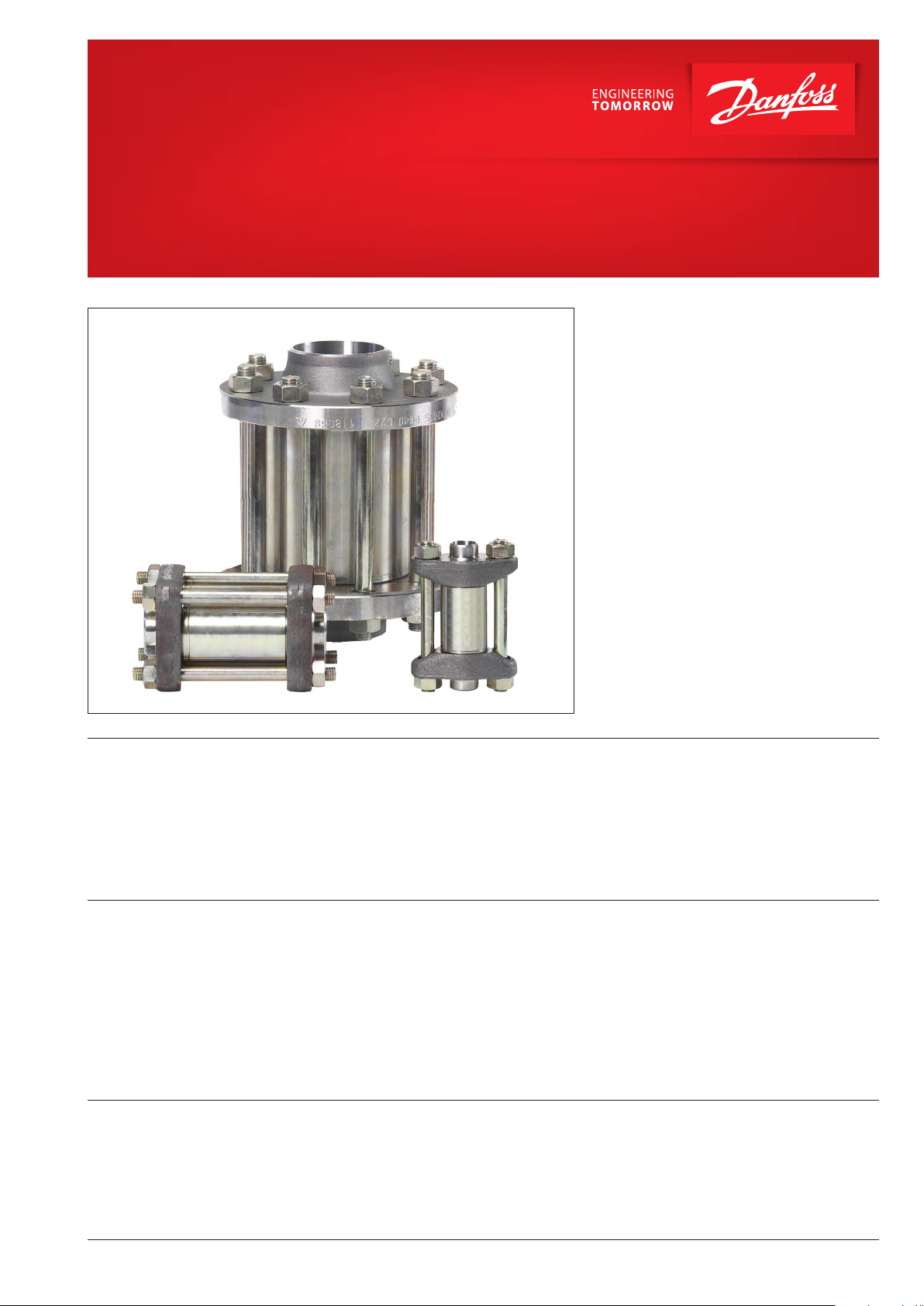
Type NRVA
Check valve type NRVA can be used in liquid,
suction and hot gas lines in refrigeration and air
conditioning plant with ammonia.
NRVA can also be used in refrigerating systems
with fluorinated refrigerants.
When the NRVA is used in liquid lines where
cold, thick oil or impurities may be present, it
is recommended that the standard spring be
replaced by a special spring. See ordering table.
Features • Ensures correct direction of flow.
• Valve housing made of steel.
• Available for 40 bar g / 580 psig working
pressure.
• Large range of flanges with connection
dimensions in accordance with standards: DIN,
ANSI, SOC, SA and FPT.
Design
Connections
There is a very wide range of connection
possibilities with NRVA check valves:
• Welding, DIN (2448)
• Welding, ANSI (B 36.10)
• Welding socket, ANSI (B 16.11)
• Solder connection, DIN (2856)
• Solder connection, ANSI (B 16.22)
• FPT internal thread, NPT
(ANSI/ASME B 1.20.1)
• Fitted with damping piston that makes the
valves suitable for installation in lines where
pulsation can occur, e.g. in the discharge line
from the compressor.
• Classification: DNV, CRN, BV, EAC etc.
To get an updated list of certification on the
products please contact your local Danfoss
Sales Company.
Gaskets:
Do not contain asbestos.
Valve cone:
The valve cone has a teflon tightening ring.
Teflon tightening ring renders perfect sealing at a
minimum closing force.
© Danfoss | DCS (mwa) | 2018.11
AF251686497757en-001012 | 43
Page 2
Check valves, type NRVA
Technical data • Refrigerants
Applicable to HCFC, HFC and R717 (Ammonia).
For further information please see installation
• Pressure range
The valve is designed for:
Max. working pressure: 40 bar g / 580 psig.
instruction for NRVA.
Use with flammable hydrocarbons cannot be
recommended; please contact Danfoss.
• Temperature range
-50 – 140 °C / -58 – 284 °F.
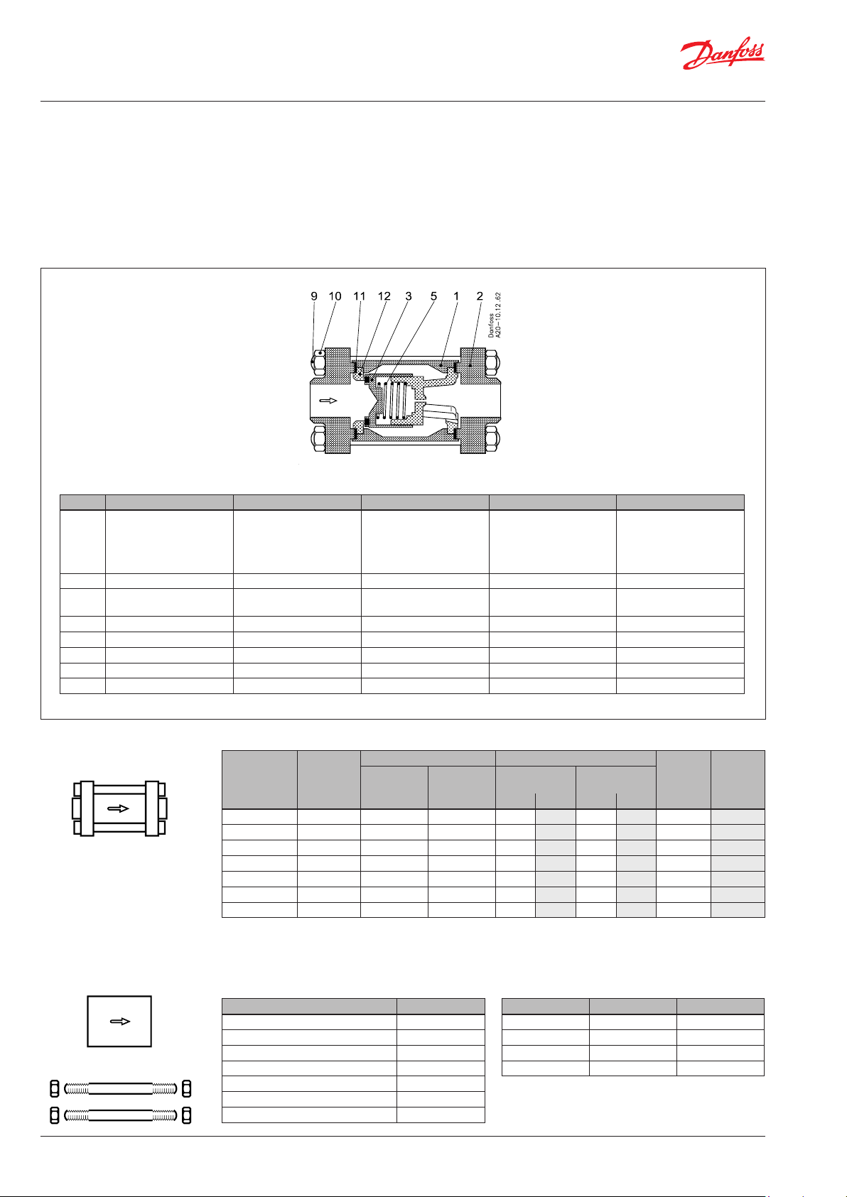
Material specification
Material specification for NRVA check valves
No. Part Material DIN ISO ASTM
1 Housing Steel G20Mn5QT *)
2 Flanges Steel RSt. 37-2, 10025 Fe360 B, 630 Grade C, A 283
3 Valve cone Stainless steel
Teflon
5 Spring Steel
9 Bolts Stainless steel A2-70
10 Nut Stainless steel
11 Gasket Non asbestos
12 Valve seat Steel
*) NRVA 40 / NRVA 50 housing material is TTSt 35N until January 2006
EN10213-3
--------------------------------------P285QH
EN10222-4
LCC, A352
--------------------------------------LF2,A350
Ordering
44 | AF251686497757en-001012
Complete valves incl. DIN 2448 flange:
Weld flange
Type
NRVA 15
NRVA 20
NRVA 25 1 020-2002 020-2317 0.12 1.7 0.3 4.4 19 22
NRVA 32 1 1⁄4 020-2003 020-2317 0.12 1.7 0.3 4.4 20 23
NRVA 40 1 1⁄2 020-2004 020-2327 0.07 1.0 0.4 5.8 44 51
NRVA 50 2 020-2005 020-2327 0.07 1.0 0.4 5.8 44 51
NRVA 65 2 1⁄2 020-2006 020-2337 0.07 1.0 0.4 5.8 75 87
1
) A special type spring can be supplied to replace the standard valve spring.
2
) Dp = the minimum pressure differential at which the valve is completely open.
3
) The kv value is the flow of water in m3/h at a pressure drop across valve of 1 bar, ρ = 1000 kg/m3.
4
) The Cv value is the flow of water in gal/min at a pressure drop across valve of 1 psig, ρ = 10 lbs/gal.
connection
[in] [bar[ [psig] [bar] [psig] [m3/h] [gal/min]
1
⁄2 020-2000 020-2307 0.12 1.7 0.3 4.4 5 6
3
⁄4 020-2001 020-2307 0.12 1.7 0.3 4.4 6 7
Valve body without flanges:
Type Code no.
NRVA 15 020-2020
NRVA 20 020-2020
NRVA 25 020-2022
NRVA 32 020-2022
NRVA 40 020-2024
NRVA 50 020-2024
NRVA 65 020-2026
Code no. Dp 2)
Valve Spec. spring 1)
standard spring
Staybolts and gaskets
Type Dimensions Code no.
NRVA 15 / 20 M 12 × 115 mm 006-1107
NRVA 25 / 32 M 12 × 148 mm 006-1135
NRVA 40 / 50 M 12 × 167 mm 006-1137
NRVA 65 M 16 × 200 mm 006-1138
With
With
spec. spring 1)
kv value 3) Cv value 4)
© Danfoss | DCS (mwa) | 2018.11
Page 3

Check valves, type NRVA
Flange connections Danfoss flange sets excluding gaskets, bolts and
nuts, are specially made for the Danfoss product
range and must only be used for the purpose
described.
Size
DIN
ANSI
Size
[mm]
[in]OD[mm]T[mm]OD[in]T[in]
Butt welding DIN (2448)
3
10
⁄8 18 2 0.710 0.079 1.3 NRVA 15/20 027N1112
1
15
⁄2 22 2.5 0.866 0.098 1.3 NRVA 15/20 027N1115
3
20
⁄4 26.9 2.3 1.059 0.091 1.3 NRVA 15/20 027N1120
25 1 33.7 2.6 1.327 0.103 4 NRVA 25/32 027N1026
32 1 1⁄4 42.4 2.6 1.669 0.102 4 NRVA 25/32 027N1033
40 1 1⁄2 48.3 2.6 1.902 0.103 6 NRVA 40/50 027N1042
50 2 60.3 2.9 2.370 0.110 6 NRVA 40/50 027N1051
65 2 1⁄2 76.1 2.9 3.000 0.110 8 NRVA 65 027N1055
Size
Size
[mm]
[in]OD[mm]T[mm]OD[in]T[in]
Butt welding ANSI B 36.10
3
10
⁄8 17.2 3.2 0.677 0.126 1.3 NRVA 15/20 027N2020
1
⁄2
15
20
25 1 33.7 4.6 1.327 0.181 4 NRVA 25/32 027N2023
32 1 1⁄4 42.4 4.9 1.669 0.193 4 NRVA 25/32 027N2024
40 1 1⁄2 48.3 5.1 1.902 0.201 6 NRVA 40/50 027N2025
50 2 60.3 3.9 2.370 0.150 6 NRVA 40/50 027N2026
65 2 1⁄2 73.0 5.2 3.000 0.200 8 NRVA 65 027N2027
21.3 3.7 0.839 0.146 1.3 NRVA 15/20 027N2021
3
⁄4 26.9 4.0 1.059 0.158 1.3 NRVA 15/20 027N2022
Flange
Flange
Select the valve based on capacity and then
select the size of flanges most suitable for the
application, which can be mounted on the valve.
For use with valve housing size Code no.
type
For use with valve housing size Code no.
type
SOC
SA
Size
[mm]
Size
[in]ID[mm]T[mm]ID[in]T[in]L[mm]L[in]
Flange
type
For use with valve
housing size
Code no.
Socket welding ANSI (B 16.11)
3
10
⁄8 17.8 4.1 0.701 0.161 10 0.394 1.3 NRVA 15/20 027N2010
1
15
⁄2 22 4.8 0.866 0.189 10 0.394 1.3 NRVA 15/20 027N2011
3
20
⁄4 27.4 5.0 1.079 0.197 13 0.512 4 NRVA 25/32 027N2012
25 1 34.1 5.8 1.343 0.228 13 0.512 4 NRVA 25/32 027N2013
32 1 1⁄4 42.9 6.0 1.689 0.236 13 0.512 4 NRVA 25/32 027N2016
40 1 1⁄2 49.0 6.5 1.929 0.254 13 0.512 6 NRVA 40/50 027N2015
Size
[mm]
Size
[in]ID[mm]
[in]
ID
L
[mm]L[in]
Flange
type
For use with valve
housing size
Code no.
Soldering DIN (2856)
16 16.07 15 1.3 NRVA 15/20 027L1116
22 22.08 22 1.3 NRVA 15/20 027L1122
35 35.07 25 4 NRVA 25/32 027L2335
54 54.09 33 4 NRVA 40/50 027L2554
Soldering (ANSI B 16.22)
5⁄8 0.628 0.807 1.3 NRVA 15/20 027L1117
7⁄8 0.878 0.866 1.3 NRVA 15/20 027L1123
1 3⁄8 1.375 0.984 4 NRVA 25/32 027L2335
2 1⁄8 2.125 1.300 4 NRVA 40/50 027L2554
© Danfoss | DCS (mwa) | 2018.11
To be continued next page.
AF251686497757en-001012 | 45
Page 4

Check valves, type NRVA
Flange connections
(Continued)
FPT
Dimensions and weights
Size
[mm]
Size
Inside pipe thread
[in]
Flange
type
For use with valve
housing size
Code no.
FPT inside pipe thread, NPT (ANSI/ASME B 1.20.1)
10 3⁄8 ( 3⁄8 × 18 NPT) 1.3 NRVA 15/20 027G1005
1
15
⁄2 (1⁄2 × 14 NPT) 1.3 NRVA 15/20 027G1006
3
20
⁄4 (3⁄4 × 14 NPT) 4 NRVA 25/32 027G1007
Example
NRVA 32 with 1 1⁄4" flanges for ANSI butt welding:
NRVA 32 + bolts + flanges (set) =
020-2022 + 006-1135 + 027N2024
NOTE:
The flanges sets are exclusive gaskets,
bolts and nuts.
Type L L
115 50 80 1.4 kg
NRVA 15 – 20
NRVA 25 – 32
NRVA 40 – 50
NRVA 65
1
) Without flanges
[mm]
[in]
4.53 1.97 3.15 3.09 lb
138 74 ∅ 83 3.0 kg
[mm]
[in]
5.43 2.91 ∅ 3.27 6.61 lb
172 94.5 ∅ 103 5.0 kg
[mm]
[in]
6.77 3.72 ∅ 4.05 11.02 lb
[mm]
226 124 ∅ 185 13.0 kg
8.90 4.88 ∅ 7.28 28.66 lb
[in]
1
) B Weight
1
46 | AF251686497757en-001012
© Danfoss | DCS (mwa) | 2018.11
 Loading...