

Page 1
Data sheet
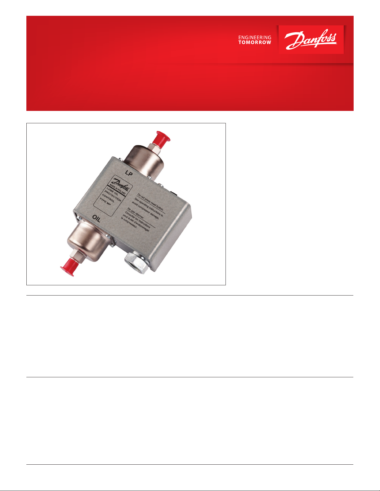
Differential pressure switch / Lube oil protection control
MP 54 and MP 55
MP 54 and MP 55 oil dierential pressure switches
are used as safety switches to protect refrigeration
compressors against low lubricating oil pressure.
If the oil pressure fails, the switch will stop the
compressor after a predetermined time period has
elapsed.
MP 54 and MP 55 are used in refrigerating systems
using HCFC and non-ammable HFC refrigerants.
MP 54 has a xed dierential pressure setting. It
also incorporates a thermal time relay with a xed
release time setting.
MP 55 have adjustable dierential pressure and are
available with thermal time relay.
Features
Approvals
© Danfoss | DCS (jmn) | 2016.11 DKRCC.PD.CG0.C4.22 | 520H11527 | 1
• Fixed and adjustable dierentials available
• Extremely narrow switch dierential accuracy
• Reliable, long life stainless steel bellows
• Sturdy metal cover and universal mounting hole
patterns
• Integral ½ NPSM swivel cable connector allows
direct attachment of ½ in. male pipe thread
connector
UL listed for USA and Canada, le E31024
• Simple manual trip, electrical test function
eliminates need of tools and test “jumper” wires
• Standard four-wire hook-up
• Can be used for HCFC and non-ammable
HFC refrigerants
Page 2
Data sheet | Dierential pressure switch / Lube oil protection control, MP 54 and MP 55
Materials in contact
with the medium
Technical data
Unit type Material
MP 54
MP 55
MP with capillary tube
Ambient temperature
Stainless steel 19/11, no. 1.4306 to EN 10088
Deep-drawn steel plate, no. 1.0338 to EN 10130
Free cutting steel, no. 1.0718 to EN 10277
Copper Cu-DHP,
no. CW024A acc. to EN 12450
The time relay is temperature-compensated
in the range - 40 – 140 °F
Switch dierential Maximum 2.8 psi
Maximum working pressure MWP = 245 psig
Maximum test pressure Pe = 320 psig
Control voltage 240 or 120 V AC or DC
Permissible voltage variation -15 – 10%
Contact load of time
relay output contacts M-S
240 V AC: 2 FLA
240 V DC: 0.2 FLA
Electrical connection NPSM
Max. bellows temperature
Cable entry
212 °F
Integral ½ in. female NPSM swiwel cable connector allows
direct attachment of ½ in. male pipe thread connector.
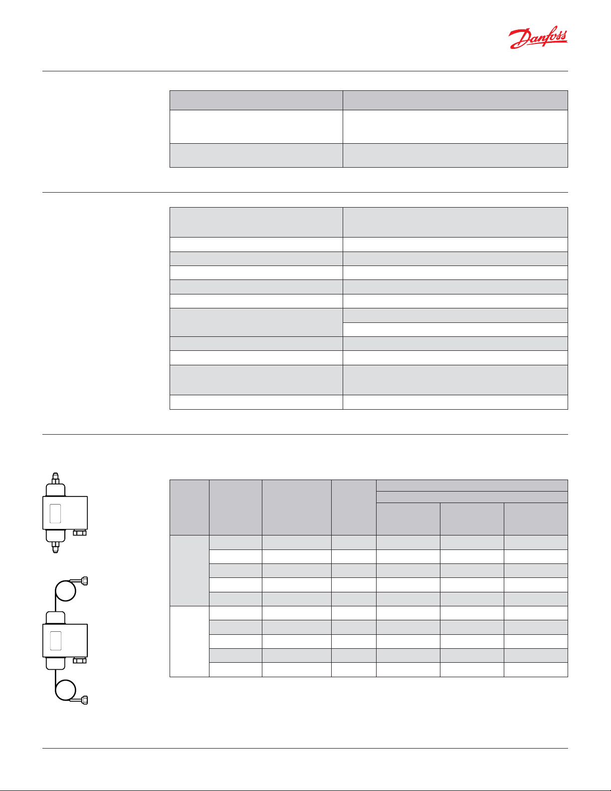
Ordering
Enclosure ~NEMA 1
For R22, R134a, R404A, R407A, R407C, R407F, R422B, R422D, R448A, R449A, R450A, R452A, R507A, R513A
For complete list of approved refrigerants, visit www.products.danfoss.com and search for individual code
numbers, where refrigerants are listed as part of technical data.
Connection
Code no.
¼ in are nut
with 36 in
capillary tube
¼in are nut
with 88 in
capillary tube
–
Typ e
Control
dierential
∆p
Regulation
range
LP side
[psi] [inHg] – [psi] [s]
6.0 29 inHg – 175 psi 45 060B200866 – –
6.0 29 inHg – 175 psi 45 – 060B205066 –
MP 54
9.0 29 inHg – 175 psi 90 060B200266 – –
9.0 29 inHg – 175 psi 120 060B200366 2) – –
9.0 29 inHg – 175 psi 120 – 060B205366 2)
4.3 – 65 29 inHg – 175 psi 45 – 060B205466 –
4.3 – 65 29 inHg – 175 psi 60 060B201266 1) – –
MP 55
4.3 – 65 29 inHg – 175 psi 90 060B200666 – –
4.3 – 65 29 inHg – 175 psi 120 060B200766 – –
4.3 – 65 29 inHg – 175 psi 120 – 060B205766 –
1
) With glow lamp that remains on during normal
operation of compressor.
2
) Three-wire hook-up
Time relay
delay time
¼ in
are
Note:
When time delay is energized which also means that
min. permisible oil pressure (dierential ∆p) is reached,
light goes out.
© Danfoss | DCS (jmn) | 2016.112 | 520H11527 | DKRCC.PD.CG0.C4.22
Page 3
Data sheet | Dierential pressure switch / Lube oil protection control, MP 54 and MP 55
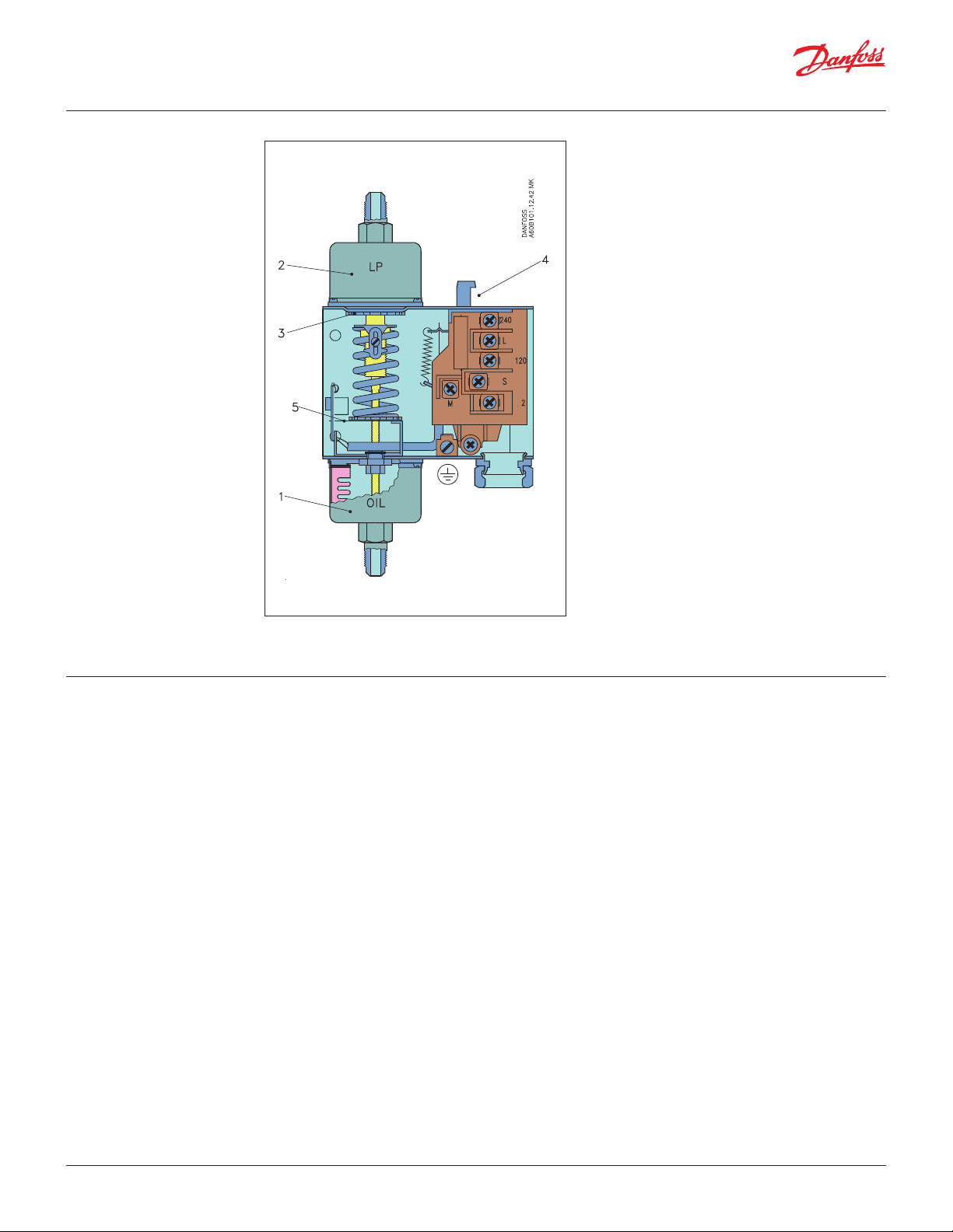
Design
1. Connection to pressure
side of lubrication
system, OIL
2. Connection to suction side
of refrigeration plant, LP
3. Setting disc (MP 55)
4. Reset button
5. Test device
The operation of the pressure switch is based only
on the dierential pressure, i.e. the dierence in
pressure between the two counteracting bellows,
whereas it is independent of the absolute pressure
acting on both bellows.
The MP 55 can be set for dierent dierential
pressures by the setting disc (3). The set dierential
pressure can be read from the internal scale.
The MP 54 has a xed dierential and has no
pressure setting disc. The factory-set dierential
pressure is stamped on the front plate of the
switch.
Terminology
Dierential range
The pressure dierence between LP and OIL
connections within which the control can be set to
operate.
Scale reading
The dierential between the oil pump pressure and
the pressure in the crankcase that exists at the
moment the contact system cuts in current to the
time relay on falling oil pressure.
Operating range
The pressure range on the LP connection within
which the switch can operate.
Contact dierential
The pressure rise above the set dierential
pressure (scale reading) necessary to cut o
current to the time relay.
Release time
The period for which the dierential pressure
control allows the compressor to run with too low
an oil pressure during start-up and operation.
© Danfoss | DCS (jmn) | 2016.11 DKRCC.PD.CG0.C4.22 | 520H11527 | 3
Page 4
Data sheet | Dierential pressure switch / Lube oil protection control, MP 54 and MP 55
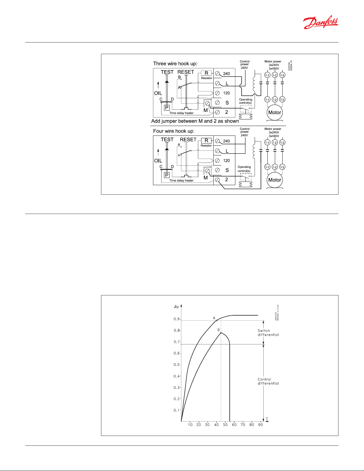
Electrical diagram
Function
If there is no oil pressure on starting, or if the oil
pressure falls below the set pressure during
operation, the compressor will stop after the
release time has elapsed. The electrical circuit is
divided into two completely separate circuits,
a safety circuit and an operational circuit.
The timer in the safety circuit is activated when the
eective lubricating oil pressure, the oil dierential
pressure (the dierence between the oil pump
pressure and suction pressure), is lower than the set
value.
[bar]
The timer is deactivated when the oil dierential
pressure is more than the set value plus the contact
dierential.
The two diagrams below explain the terms
oil dierential pressure” and “contact dierential”,
both have to be considered when using oil
dierential pressure switches.
The rst diagram shows the function of the
dierential switch during start; the second shows
the function of the switch during operation.
On start-up
[s]
© Danfoss | DCS (jmn) | 2016.114 | 520H11527 | DKRCC.PD.CG0.C4.22
Page 5
Data sheet | Dierential pressure switch / Lube oil protection control, MP 54 and MP 55
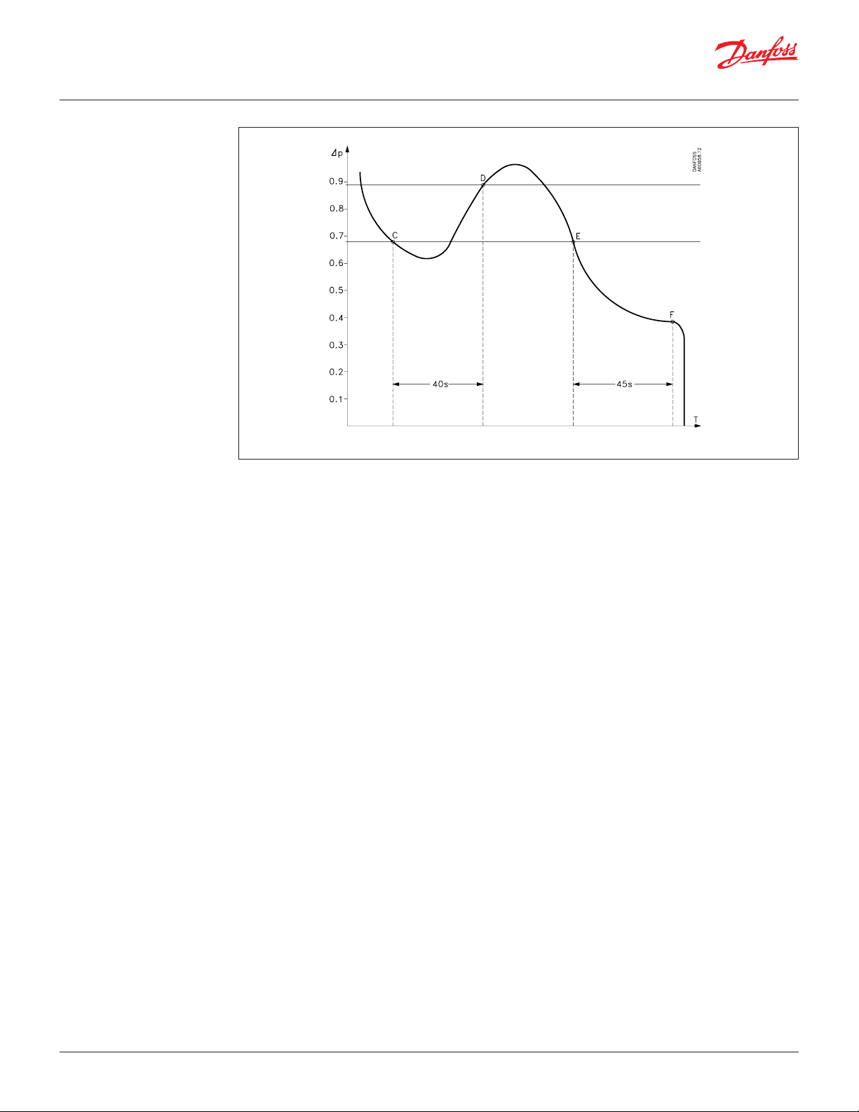
[bar]
During operation 1 bar = 14.5 psi
Pos. A:
Normal start-up
The lubricating oil pressure is built up during start
to the set/xed dierential plus the contact
dierential, before the timer cuts out (in this
example, after 45 seconds). At point A contacts
T1-T2 open and timer (e) is stopped, i.e. normal
lubricating oil conditions for the compressor have
been established.
Pos. B:
The lubricating oil pressure does not reach the set/
xed dierential plus the contact dierential
before the timer period elapses.
At point B the timer cuts out operational circuit
L-M and the compressor stops.
If a signal source is connected to terminal S, it will
be activated. Restart can only be performed after
about 2 minutes by activation of the reset button,
provided the cause of the fault has been
determined.
Pos. C:
The lubricating oil pressure falls during operation
to a value lower than the set/xed dierential. At
point C, safety circuit T1-T2 cuts in and the timer is
activated.
Pos. D:
The lubricating oil pressure reaches the set/xed
dierential plus the contact dierential before the
timer period elapses. At point D, safety circuit T1-T2
cuts out and the timer is stopped, i.e. normal
lubricating oil conditions for the compressor have
been established.
[s]
Pos. E:
The lubricating oil pressure falls to a value lower
than the set/xed dierential during operation. At
point E, safety circuit T1-T2 cuts in and the timer is
activated.
Pos. F:
The lubricating oil pressure remains lower than the
set/xed dierential. At point F the timer cuts out
operational circuit L-M and the compressor stops. If
a signal source is connected to terminal S, it will be
activated. Restart can only be performed after
about 2 minutes by activation of the reset button,
provided the cause of the fault has been
determined.
After start-up
It is important that a function check should be
made to ensure that the dierential pressure switch
is operating as it should. This check can be made
by pressing the test device (inside the unit on the
left hand side).
When the test device is pressed down and held in
this position the compressor motor should stop
after the release time determined by the time relay
has elapsed.
© Danfoss | DCS (jmn) | 2016.11 DKRCC.PD.CG0.C4.22 | 520H11527 | 5
Page 6
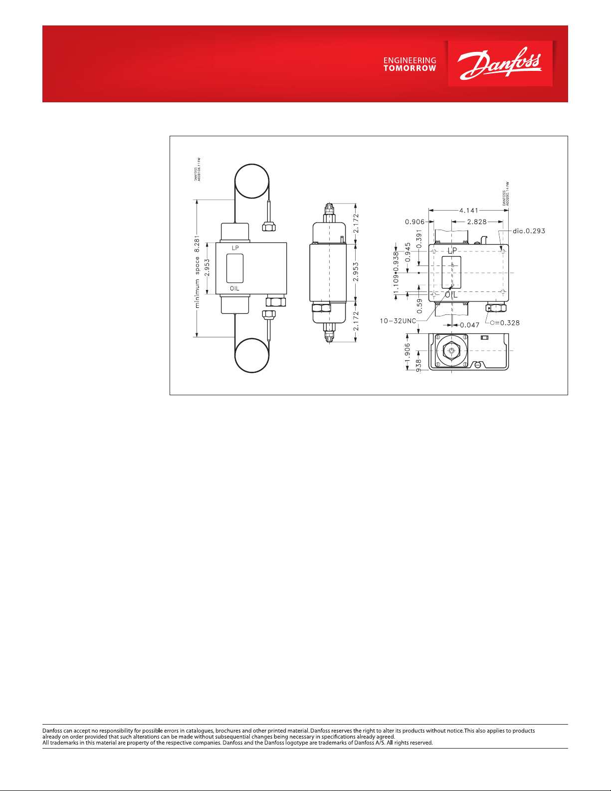
Dimensions [in]
and weights [lb]
MP 54, MP 55
Net weight:
approx. 1.8 lbs
© Danfoss | DCS (jmn) | 2016.11 DKRCC.PD.CG0.C4.22 | 520H11527 | 6
 Loading...