

Page 1

■ Contents
MCD 200 Design Guide
MCD 200 Series Overview
Description ............................................................................................................. 3
Ratings ................................................................................................................... 4
General Technical Data ........................................................................................... 5
Mechanical Installation ........................................................................................... 7
Dimensions and Weights ........................................................................................ 7
Cable Size .............................................................................................................. 9
Semiconductor Fuses ............................................................................................ 9
Frequently Asked Questions ................................................................................... 10
.......................................................................... 3
MCD 201 .............................................................................................................. 12
Electrical Schematic ............................................................................................... 12
Control Circuits ...................................................................................................... 13
Functionality ........................................................................................................... 13
Indication ............................................................................................................... 14
Fault Finding ........................................................................................................... 14
MCD 202 .............................................................................................................. 15
Electrical Schematic ............................................................................................... 15
Control Circuits ...................................................................................................... 15
Functionality ........................................................................................................... 16
Motor Thermistor Protection ................................................................................... 18
Indication ............................................................................................................... 18
Fault Finding ........................................................................................................... 18
Accessories ....................................................................................................... 19
Overview ................................................................................................................ 19
MCD 200 Remote Operator ................................................................................... 19
MCD 200 Modbus Module ..................................................................................... 19
MCD 200 Profibus Module ..................................................................................... 19
MCD 200 DeviceNet Module .................................................................................. 19
MCD 200 AS-i Module ........................................................................................... 19
MCD PC Software .................................................................................................. 19
Soft Start Ap plication Guide ..................................................................... 21
Reduced Voltage Starting ....................................................................................... 21
Types of Soft Start Control ............................................................................. ........ 22
Understanding Soft Starter Ratings ........................................................................ 22
Model Selection ..................................................................................................... 23
Typical Applications ................................................................................................ 23
Power Factor Correction ........................................................................................ 24
MG.17.C2.02 - VLT is a registered Danfoss trademark
1
Page 2
■Warnings
MCD 200 Design Guide
■High Voltage Warning
The MCD 200 contains dangerous voltages
when co nnected to line voltage. Only a
competent electrician should carry out
the electrical installation. Improper instal lation of the
motor or the MCD 200 may cause equipment failure,
serious injury or death. Follow this manual, National
Electrical Code (NEC®) and local safety codes.
■Safety Regulations
1. The soft starter must be disconnected from the
mains if repair work is to be carried out.
It is the responsibilit y of the user or
the person installing the MCD 200 to
provide proper grounding and branch
circuit protection according to the National Electrical
Code (NEC®) and local safety codes.
■Warning Against Unintended Start
1. The motor can be brought to a stop by means
of digital or bus commands while the soft starter
is connected to the mains.
If personal safety considerations make it necessary
to ensure that no unintended start occurs,
stop functions are not sufficient.
2. A motor that has been stopped may start if
faults occur in the electronics of the soft starter,
or a temporary fault in the supply mains or
the motor connection ceases.
correction, if used, must be connected on the
mains side of the soft starter.
2. Do not apply incorrect voltages to the MCD
200 control inputs.
Electrostatic Precaution: Electrostatic
discharge (E SD). Many electronic
components are sensitive to static
electricity. Voltages so low that they cannot b e
felt, seen o r heard, can reduce the life, affect
performance, or completely destroy sensitive
electronic co mponents. When performing service,
proper ESD equipment should be used to prevent
possible damage from occurring.
these
■Symbols Used in this Manual
When reading this manual you will come across
different symbols that require special attention.
The symbols used are the following:
NB!:
Indicates something to be noted by the reader
Indicates a general warning
Indicates a high voltage warning
■Avoiding Soft Starter D amage
Please read and follow all instructions in this manual.
Additionally, take special note of the following:
1. Do not connect power factor correction capacitors
to the soft starter output. Static power factor
2
MG.17.C2.02 - VLT is a registered Danfoss trademark
Page 3
■MCD 200 Series Overview
■Description
The Danfoss MCD 200 Soft Starter series
comprises two separate ranges:
• MCD 201
• MCD 202
MCD 201 and MCD 202 soft starters share a
common power and mechanical design, but offer
different levels of functionality.
MCD 201 soft starters provide TVR (Timed Voltage
Ramp) starting and stopping control and are designed
for use with an external motor protection device.
MCD 202 soft starters provide Current Limit
starting control, TVR soft stop and include a range
of motor protection functions.
NB!:
This manual makes reference to MCD
200, MCD 201 and MCD 202. The MCD
200 designation is used when referring to
characteristics common to both the MCD 201 and
MCD 202 ranges. In all other cases the text refers
to the specific range MCD 201 or MCD 202.
MCD 200 Design Guide
Overview
MCD 200 Series
MCD 200 soft starters include an integral bypass
function that bypasses the soft starter SCRs during
run. This minimises heat dissipation during run
and makes the MCD 200 suitable for installation
within non-ventilated enclosures without th
for an external bypass contactor.
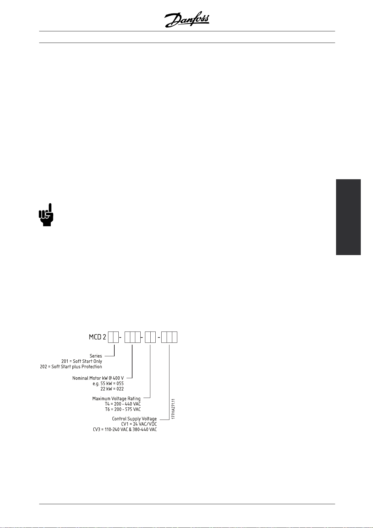
■Ordering Type Code
e need
MG.17.C2.02 - V LT is a registered Danfoss trademark
3
Page 4
■Ratings
MCD 200 Design Guide
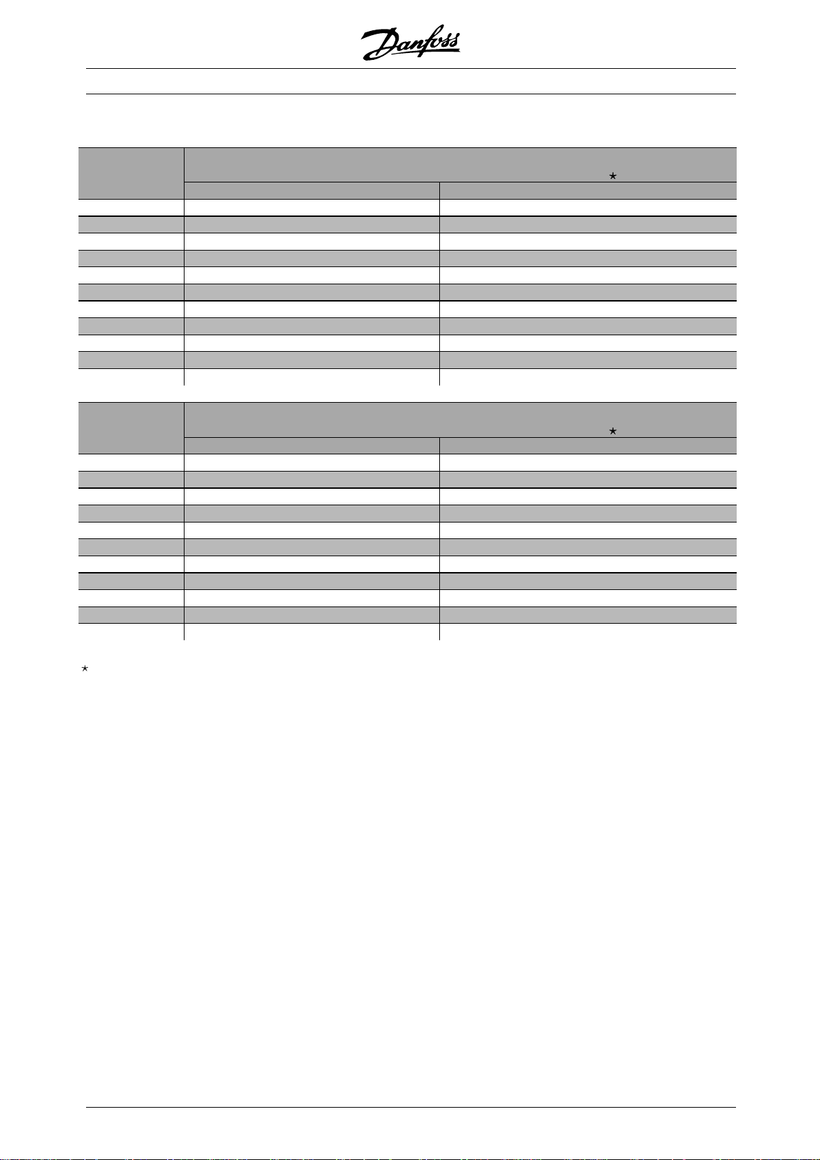
MCD 200 Model
Continuous Ratings (Internally bypassed)
@ 40 °C Ambient Temperature, <1000 metres
Normal Heavy
007 18 A: AC53b 4-6:354 17 A: AC53b 4-20:340
015 34 A: AC53b 4-6:354 30 A: AC53b 4-20:340
018 42 A: AC53b 4-6:354 36 A: AC53b 4-20:340
022 48 A: AC53b 4-6:354 40 A: AC53b 4-20:340
030 60 A: AC53b 4-6:354 49 A: AC53b 4-20:340
037 75 A: AC53b 4-6:594 65 A: AC53b 4-20:580
045 85 A: AC53b 4-6:594 73 A: AC53b 4-20:580
055 100 A: AC53b 4-6:594 96 A: AC53b 4-20:580
075 140 A: AC53b 4-6:594 120 A: AC53b 4-20:580
090 170 A: AC53b 4-6:594 142 A: AC53b 4-20:580
110 200 A: AC53b 4-6:594 165 A: AC53b 4-20:580
MCD 200 Model
Continuous Ratings (Internally bypassed)
@ 50 °C Ambient Temperature, <1000 metres
Normal Heavy
007 17 A: AC53b 4-6:354 15 A: AC53b 4-20:340
015 32 A: AC53b 4-6:354 28 A: AC53b 4-20:340
018 40 A: AC53b 4-6:354 33 A: AC53b 4-20:340
022 44 A: AC53b 4-6:354 36 A: AC53b 4-20:340
030 55 A: AC53b 4-6:354 45 A: AC53b 4-20:340
037 68 A: AC53b 4-6:594 59 A: AC53b 4-20:580
045 78 A: AC53b 4-6:594 67 A: AC53b 4-20:580
055 100 A: AC53b 4-6:594 87 A: AC53b 4-20:580
075 133 A: AC53b 4-6:594 110 A:: AC53b 4-20:580
090 157 A: AC53b 4-6:594 130 A: AC53b 4-20:580
110 186 A: AC53b 4-6:594 152 A: AC53b 4-20:580
Contact Danfoss for other ratings.
Example
For 22 kW model: 48 A: AC53b: 4-6:354
48 A: Starter current rating.
AC53b: Load category for soft starters
with SCRs bypassed during
run.
4-6: 400% start current for 6
seconds.
354: 354 seconds between the
end of one start to the
beginning of the next start
(i.e. 10 starts per ho ur).
4
MG.17.C2.02 - VLT is a registered Danfoss trademark
Page 5

MCD 200 Design Guide
■General Technical Data
Mains Supply (L1, L2, L3):
MCD 200-xxx-T4-xxx .............................................................................. 3 x 200 VAC ~ 440 VAC (+10% / - 15%)
MCD 200-xxx-T6-xxx .............................................................................. 3 x 200 VAC ~ 575 VAC (+10% / - 15%)
Supply frequency (at start) ................................................................................................................ 45 Hz - 66 Hz
Control Supply (A1, A2, A3):
MCD 200-xxx-xx-CV1 .......................................................................................................... 24 VAC/VDC (± 20%)
MCD 200- xxx-xx-CV3 .......................................... 110-240 VAC (+10% / - 15%) or 380-440 VAC (+10% / - 15%)
Control Inputs
Start Terminal N1 ............. ....................................................................................... Normally Open, 300 VAC max.
Stop Terminal N2 ............. ..................................................................................... Normally Closed, 300 VAC max.
Relay Outputs
Main Contactor (Terminals 13 & 14) ................................................................................................ Normally Open
Main Contactor (Terminals 13 & 14) .................................................... 6 A, 30 VDC resistive / 2 A, 400 VAC, AC11
Programmable Relay (Terminals 23 & 24) ...................................... .................................................. Normally Open
Programmable Relay (Terminals 23 & 24) ............................................ 6 A, 30 VDC resistive / 2 A, 400 VAC, AC 11
Environmental
Degree of protection MCD 200-007 to MCD 200-055 .................................................................................... IP20
Degree of protection MCD 200-075 to MCD 200-110 .................................................................................... IP00
Operating Temperatures ............................................................................................................... -10 °C / + 60 °C
Humidity ................................................................................................................... 5% to 95% Relative Humidity
Pollution Degree ........................................................................................................................ Pollution Degree 3
Vibration ................................................................................................................... IEC 60068 Test Fc Sinusoidal
Vibration ...................................................................................................... 4 Hz - 13.2 Hz: ± 1 mm displacement
Vibration ........................................................................................................................ 13.2 Hz - 100 Hz: ± 0.7 g
Overview
MCD 200 Series
EMC Emission
Equipment class (EMC) ................................................................. ............................................................. . Class A
Conducted radio frequency emission ................................................................ 0.15 MHz - 0.5 MHz: < 90 dB (µV)
Conducted radio frequency emission ............................................. ........................ 0.5 MHz - 5 MHz: < 76 dB (µV)
Conducted radio frequency emission ............................................. ....................... 5 MHz - 30 MHz: 80-60 dB (µV)
Radiated radio frequency emission ................................................................. 30 MHz - 230 MHz: < 30 dB (µV/m)
Radiated radio frequency emission ............................................................. 230 MH z - 1000 MHz: < 37 dB (µV/m)
This product has been designed for Class A equipment. Use of the product in domestic environments may
cause radio interference, in which case the user may be required to employ additional mitigation methods.
EMC Immunity
Electrostatic discharge .......................................................................... 4 kV contact discharge, 8 kV air discharge
Radio frequency electromagnetic field ............................................................. 0.15 MHz - 1000 MHz: 140 dB (µV)
Rated impulse withstand voltage (Fast transients 5/50 ns) ............................................................ 2 kV line to earth
Rated insulation voltage (Surges 1.2/50 µs – 8/20 ms) ........................................ 2 kV line to earth, 1 kV line to line
Voltage dip and short time interruption ................................................................. 100 ms (at 40% nominal voltage)
Short Circuit
Rated short-circuit current MCD 200-007 to MCD 200-037 ............................................................................ 5 kA
Rated short-circuit current MCD 200-045 to MCD 200-110 .......................................................................... 10 kA
MG.17.C2.02 - V LT is a registered Danfoss trademark
5
Page 6

MCD 200 Design Guide
Heat Dissipation
During Start ................................................................................................................................. 3 watts / ampere
During Run .............................................................................................................................................. < 4 watts
Standards Approvals
C ................................................................................................................................................. IEC 60947-4-2
UL / C-UL .................................................................................................................................................... UL508
CE .................................................................................................................................................. IEC 60947-4-2
CCC ................................................................................................................................................... GB 14048.6
6
MG.17.C2.02 - VLT is a registered Danfoss trademark
Page 7
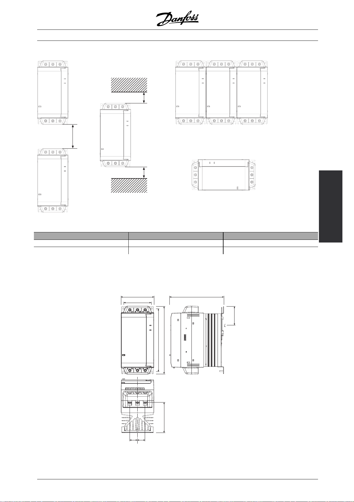
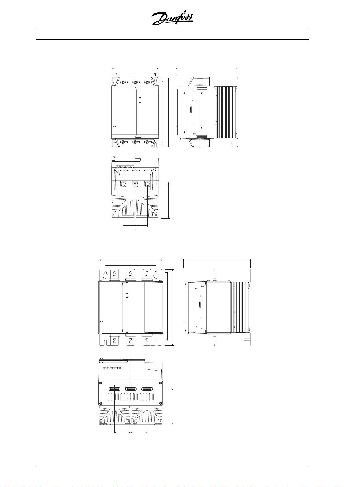
■Mechanical Installation
1L13L25L3
1L13L25L3
50 (1.97)
1L13L25L3
MCD 200 Design Guide
1L13L25L3
1 L1 3 L2 5 L3
177HA201.11
2T14T26T3
2T14T26T3
2T14T26T3
2T14T26T3
100 (3.93)
1L13L25L3
2T14T26T3
50 (1.97)
1L13L25L3
MCD 200 FLC * 0.85
2T14T26T3
mm (inch)
MCD 200 Din Rail Foot Mounting
MCD 200-007 ~ MCD 200-030 30 mm Yes
MCD 200-037 ~ MCD 200-110 Not available Yes
■Dimensions and Weights
mm (inch)
MCD 201-007 ~ MCD 201-030 (2.2 kg / 4.8 lb)
MCD 202-007 ~ MCD 202-030 (2.4 kg / 5.3 lb)
98 (3.86) 165 (6.50)
82 (3.23)
2T14T26T3
Overview
MCD 200 Series
177HA242.11
23
23
(0.9)
(0.9)
MG.17.C2.02 - V LT is a registered Danfoss trademark
188 (7.40)
203 (7.99)
90.5 (3.56)
55 (2.17)
C
7
Page 8
MCD 200 Design Guide
MCD 201-037 ~ MCD 201-055 (4.0 kg / 8.8 lb)
145 (5.71) 193 (7.60)
124 (4.88)
177HA243.11
MCD 202-037 ~ MCD 202-055 (4.3 kg / 9.5 lb)
196 (7.71)
215 (8.46)
110.5 (4.35)
37
37
(1.46)
(1.46)
MCD 201-075 ~ M CD 201-110 (6.1 kg / 13.5 lb)
202 (7.95) 214 (8.43)
160 (6.30)
177HA244.11
MCD 202-075 ~ MCD 202-110 (6.8 kg / 15.0 lb)
204 (8.03)
240 (9.45)
114.5 (4.5)
51
51
(2.0)
(2.0)
8
MG.17.C2.02 - VLT is a registered Danfoss trademark
Page 9

■Cable Size
MCD 200 Design Guide
MCD 200-007 ~
MCD 200-030
10 - 35
(8 - 2)
10 - 35
(8 - 2)
Torx (T20)
3 - 5 Nm.
2.2 - 3.7 ft-lb.
7 mm
3 - 5 Nm
2.2 - 3.7 ft-lb
14
(0.55)
mm (inch) mm (inch)
75ºC W ire. Use copper conductors only.
■Semiconductor Fuses
Semiconductor fuses may be used with the MCD 200
soft starters. Use of semiconductor fuses will provide
Type 2 coordination and reduce the potential of SCR
damage due to transient overload currents and short
circuits. MCD 200 soft starters have been tested t
achieve Type 2 coordination with semiconductor fuses.
mm2 (AWG)
MCD 200-037 ~
MCD 200-055
25 - 50
(4 - 1/0)
25 - 50
(4 - 1/0)
Torx (T20)
4 - 6 Nm.
2.9 - 4.4 ft-lb.
7 mm
4 - 6 Nm
2.9 - 4.4 ft-lb
o
mm2 (AWG)
MCD 200-075 ~
MCD 200-110
N.A.
26
14
(0.55)
mm (inch) mm (inch)
(1.02)
N.A.
N.A.
N.A.
11
(0.43)
8.5
(0.33)
MCD 200-007 ~
MCD 200-110
0.14 - 1.5
(26 - 16)
0.14 - 1.5
(26 - 16)
N.A.
3.5 mm
0.5 Nm max.
4.4 lb-in max.
6
(0.24)
177HA245.11
Thefollowingtableprovidesalistofsuitable
Ferraz and Bussman fuses. If selecting alternate
brands ensure the selected fuse has a lower total
2
clearing I
t rating than the SCR, and can carry start
current for the full starting duration.
Overview
MCD 200 Series
MCD 200 SCR I2t(A2s) Ferraz Fuse
European/IEC Style (North
American Style)
MCD 200-007 1150
MCD 200-015 8000
MCD 200-018 10500
MCD 200-022 15000
MCD 200-030 18000
MCD 200-037 51200
MCD 200-045 80000
MCD 200-055 97000
MCD 200-075 168000
MCD 200-090 245000
MCD 200-110 320000
6.6URD30xxxA0063
(A070URD30xxx0063)
6.6URD30xxxA0125
(A070URD30xxx0125)
6.6URD30xxxA0160
(A070URD30xxx0160)
6.6URD30xxxA0160
(A070URD30xxx0160)
6.6URD30xxxA0160
(A070URD30xxx0160)
6.6URD30xxxA0250
(A070URD30xxx0250)
6.6URD30xxxA0315
(A070URD30xxx0315)
6.6URD30xxxA0315
(A070URD30xxx0315)
6.6URD31xxxA0450
(A070URD31xxx0450)
6.6URD31xxxA0450
(A070URD31xxx0450)
6.6URD31xxxA0450
(A070URD31xxx0450)
xxx = Blade Type.
Refer Ferraz for options.
Bussman Fuse
Square Body
(170M)
Bussman Fuse
British Style
(BS88)
170M-1314 63 FE
170M-1317 160 FEE
170M-1318 160 FEE
170M-1318 180 FM
170M-1319 180 FM
170M-1321 250 FM
170M-1321 250 FM
170M-1321 250 FM
170M-1322 500 FMM
170M-3022 500 FMM
170M-3022 500 FMM
MG.17.C2.02 - V LT is a registered Danfoss trademark
9
Page 10

MCD 200 Design Guide
■Frequently Asked Questions
• What is the minimum allowable motor current
when using an MCD 201 open loop soft starter?
There is no minimum current when using an
MCD 201 open loop soft starter
• What is the minimum allowable motor
current when using an MCD 202 closed
loop soft starter?
The minimum "Motor FLC" setting is 50% of
the MCD 202 nameplate rating. All the motor
protections are based on this setting.
It is possible to operate an MCD 202 with a small kW
motor, for testing purposes. In this case, the motor
will effectively start DOL, and the MCD 202 will not
protect the motor. The starter w ill not trip, because
there is no undercurrent protection on MCD 202.
• What type of motor protection does
theMCD202have?
The MCD 202 has built-in m otor overload
protection of the electronic "thermal model" type.
The motor cu rrent is continuously monitored
and the expected temperature is calculated
based on this monitored current.
The rate of rise of the calculated motor temperature
is determined by the M otor Trip Class setting.
The lower this setting, the faster the rate of rise
of calculated motor temperature. An Overcurrent
trip (x 2 Ready L ED flashes) will occur when the
calculated temperature reaches 105%. The setting
of the Motor Trip Class pot is similar to a motor trip
class setting on a standard thermal overload relay.
An external motor protection device is not required
when using an MCD 202 soft starter. MCD 202 is
certified to conform to the IEC60947-4-2 standard
for electronic soft starters. The reliability of the
motor protection feature is part of this standard.
• How do I select an MCD 200 soft starter
for duty cycles different from those listed
in the standard ratings table?
The WinStart software package is available for
selecting soft starters for different duty cycles.
• Which MCD 200 models carry the UL mark?
All T6 models carry the UL mark.
• What are the MCD 200 operational ratings
before maintenance may be required?
The operational ratings for MCD 200 are
size-dependent, and are due to the capability
of the internal bypass relays:
Size 1 & 2 (7.5 ~ 55 kW): 1,000,000 operations
Size 3 (75 ~ 110 kW): 100,000 operations.
• When would I use a line contactor?
A line contactor may be compulsory for a specific
installation. This requirement will be the same
whether using a two-phase controlled soft
starter or a three-phase controlled soft starter
(see Product Note for more detail).
• How do I size the fuses of the motor
branch circuit (Type 1) when using an
MCD 200 soft starter?
For "Current Limit" settings ≤ 350% and start times
≤ 15 seconds, the nominal rating of standard line
supply fuses (gG) should be 1.75 x Motor FLC.
If motor rated fuses (gM) are being used, their
nominal rating should be 1.5 x Motor FLC.
For "Current Limit" settings > 350% and start
times > 15 seconds, the nominal rating of standard
line supply fuses (gG) should be 2 x Motor FLC.
If motor rated fuses (gM) are being used, their
nominal rating should be 1.75 x Motor FLC.
• When would I use semiconductor fuses?
Either when specified for an installation, or when
Type 2 coordination is required.
The MCD 200 is internally bypassed, so the SCRs
are in use only during starting and soft stopping.
• What is the current consumption of the
MCD 200 control supply?
The steady state consumption of the control supply
is 100 mA maximum, for both CV1 and CV3 models.
However, the short time inrush current at control
supply "switch-on" can be as high as 10 A for
CV3 models, and 2 A for CV1 models (due
to the SMPS power supply).
• How can the MCD 202 programmable
output relay be used?
The programmable output relay provides
an N/O contact, which can be used for a
"Trip" or "Run" output.
Trip o u t p u t :
The relay operates when the MCD 202 trips
on any fault. This can be used to operate a
shunt-trip mechanism of an upstream circuit
breaker to isolate the motor branch circuit. It
couldalsobeusedtosignalMCD202"Trip"
status to an automation system.
Run output:
The relay operates on completion of start ramp. This
can be use d to operate a contactor for power factor
correction capacitors. It could also be used to signal
MCD 202 "Run" status to an automation system.
• Is the MCD 202 suitable for flying
start application?
Yes. There is a built-in 2 second delay between
the end of one stop and the beginning of the next
start. This delay allows the motor flux to decay,
eliminating any chance of the MCD 202 tripping on
Power Circuit fault (x 1 Ready LED flash) due to
detection of motor back EMF when the start signal
is applied. The major effect of a fl ying start is on
10
MG.17.C2.02 - VLT is a registered Danfoss trademark
Page 11

the actual time the MCD 202 "current limits". The
ramp-up time will be reduced and is determined by
the motor speed on reapplication of the start signal.
• What is the remote start and stop
input impedance?
Are any special precautions necessary
during installation?
The 01/02 input impedance is approximately 400
@ 300 VAC and 5.6 k @24VAC/VDC.All
k
control wiring, for long runs, should be either twisted
pair or shielded cable with the screen earthed at
one end. Control wiring should be separated from
power cables by a minimum distance of 300 mm.
If long cable runs cannot be avoided, the
best assurance against noise interference is
to install an interposing relay in close proximity
to the MCD 200 soft starter.
• Why is it necessary to apply control voltage
before (or with) mains voltage?
There is a possibility the soft starter could arrive
at site with the internal bypass relays in "closed"
state. On first application of control voltage, the
bypass relays are commanded to open. If m ains
voltage is applied without control voltage, this step
is missed, and the motor may start DOL without
warning (see Product Note for more d etail) .
• What are the under- & over-frequency trip
points for MCD 200 soft starters?
The trip points are 40 Hz and 72 Hz. If the
frequency falls below 40 Hz or rises above 72 Hz,
the soft starter will trip (x 6 Ready LED flashes).
These trip points are not adjustable.
A supply frequency trip will also occur if all
three phases from the mains supply are lost,
or fall below approximately 120 VAC while
the soft starter is running.
A supply frequency trip will occur if t he line
contactor drops out during running.
• Will the motor start DOL if the start ramp
of MCD 201 open loop soft starter is
set to "full voltage"?
No, the MCD 201 will still provide a l imited soft
start. The voltage is ramped up from 0 to 100%
in approximately 0.25 seconds.
MCD 200 Design Guide
Overview
MCD 200 Series
MG.17.C2.02 - V LT is a registered Danfoss trademark
11
Page 12

■MCD 201
■MCD 201 Range
MCD 201 soft starters provide TVR (Timed Voltage
Ramp) starting and stopping control and are designed
for use with an external motor protection device.
■Electrical Schematic
Example 1 – MCD 201 installed with motor
protection circuit breaker.
L3L2L1
MCD 200 Design Guide
Example 2 – MCD 201 installed with m otor protection
circuit b reaker and line contactor.
L3L2L1
I>I>I
Q1
K1M
>
I>I>I
Q1
Motor
1
6A@30VDCresistive/2A400VACAC11
2
Main Contactor
>
5/L33/L21/L1
6/T34/T22/T1
3Ø
U
e
A3A2A1 N2N1
1,2
1413
177HA207.11
177HA241.10
Motor
3Ø
5/L33/L21/L1
6/T34/T22/T1
K1M
A3A2A1 N2N1
1,2
1413
Control
Voltage
177HA246.11
Example 3 – MCD 201 installed with c ircuit breaker,
overload and line contactor.
L3L2L1
I>I>I
Q1
F1
>
12
K1M
Motor
3Ø
5/L33/L21/L1
6/T34/T22/T1
K1M
A3A2A1 N2N1
1,2
Control
Voltage
1413
177HA247.11
MG.17.C2.02 - VLT is a registered Danfoss trademark
Page 13

MCD 200 Design Guide
■Control Circuits
2WireControl
OR
24 VAC/VDC (CV1)
110-240 VAC (CV3)
380-440 VAC (CV3)
177HA211.10
START/
STOP
START/
STOP
*
*
* Also resets the MCD 201
3WireControl
OR
110-240 VAC (CV3)
24 VAC/VDC (CV1)
START
STOP
*
1 Initial Torque
Value:
A3
A1
(+)
A2
(-)
N1
N2
30% - 75% Initial Torque
✭ 50%
Function:
Determines the start torque generated by the motor
when the start command is first applied.
Description of choice:
Set so that the motor begins to rotate as soon
A3
A1
A2
N1
N2
A3
A1
(+)
A2
(-)
N1
N2
as the start command is given.
U
100%
Initial Torque
(30 - 75%)
177HA249.10
2RampUp
Value:
2 - 20 seconds, Full Voltage
✭ 10 seconds
Function:
Determines the time taken for voltage to be
ramped up to line voltage.
380-440 VAC (CV3)
177HA212.10
START
STOP
*
* Also resets the MCD 201
■Functionality
User Adjustments
50%
30%
(% U)
10s
8s 12s
6s
4s
2s
Full
Voltage Start
(seconds)
70%
60%
10s
8s 12s
14s
6s
16s
4s
20s
2s
20s
No
Soft Stop
(seconds)
40%
A3
A1
A2
N1
N2
Initial Torque
U
Ramp Up
U
14s
16s
Ramp Down
U
Set to optimise motor acceleration and/or start current.
Short ramp times result in quicker acceleration and
higher start currents. Long ramp times result in
slower acceleration and lower start current.
Ramp Up
(2 - 20 seconds, Full Voltage Start)
U
100%
Initial Torque
(30 - 75%)
177HA250.10
3RampDown
Value:
2 - 20 seconds, No Soft Stop
✭ No Soft Stop
Function:
201
MCD
Sets the time of the soft stop voltage ramp. The
soft stop function extends motor deceleration
Description of choice:
177HA248.10
time by ramping down voltage supplied to the
motor when a stop is initiated.
MG.17.C2.02 - V LT is a registered Danfoss trademark
Description of choice:
Set the ramp time to optimise stopping
characteristics for the load.
13
Page 14

■Indication
(2 - 20 seconds, No Soft Stop)
U
100%
1L13L25L3
MCD 200 Design Guide
Ramp Down
177HA251.10
177HA252.10
2T14T26T3
Ready
Run
LED OFF ON FLASH
Ready No control
power
Run Motor not
running
Ready Starter
tripped
Motor
running at
full speed
Motor
starting or
stopping
■Fault Finding
Ready LED Description
Power Circuit Fault:
Check mains supply L1, L2 &
x1
L3, motor circuit T1, T2 & T3
and soft starter SCRs.
Supply Frequency:
Check supply frequency is in
x6
range
Network Comms Failure
(between accessory module
x8
and network):
Check network connections
and settings.
Starter Comms Failure (between
starter and accessory module):
x9
Remove and refit accessory
module.
14
MG.17.C2.02 - VLT is a registered Danfoss trademark
Page 15

■MCD 202
■MCD 202 Range
MCD 202 soft starters provide Current Limit
control, TVR soft stop and include a range of
motor protection features.
■Electrical Schematic
Example 1 – MCD 202 installed with system protection
circuit breaker complete with shunt trip device.
MCD 200 Design Guide
Example 2 – MCD 202 installed with syste m protection
circuit b reaker and line contactor.
L3L2L1
L3L2L1
>I>
I>I
Q1
5/L33/L21/L1
6/T34/T22/T1
A3A2A1 N2N1 0605
1,2
1413 2423
Motor
3Ø
Shunt Trip
1
6A@30VDCresistive/2A400VACAC11
2
Main Contactor
177HA253.11
1,3
Control
Voltage
I>I
Q1
K1M
■Control Circuits
2WireControl
OR
24 VAC/VDC (CV1)
110-240 VAC (CV3)
Motor
START/
STOP
>I>
3Ø
*
5/L33/L21/L1
6/T34/T22/T1
A3A2A1 N2N1 0605
1,2 1,3
1413 2423
177HA254.11
K1M
Control
Voltage
A3
A1
(+)
A2
(-)
N1
N2
U
e
177HA241.10
3
Auxiliary Relay Function = Trip (see parameter 8)
MG.17.C2.02 - V LT is a registered Danfoss trademark
A3
A1
A2
*
N1
N2
177HA211.10
380-440 VAC (CV3)
START/
STOP
* Also resets the MCD 202
15
202
MCD
Page 16

MCD 200 Design Guide
3WireControl
A3
A1
OR
110-240 VAC (CV3)
START
24 VAC/VDC (CV1)
STOP
(+)
A2
(-)
N1
*
N2
A3
A1
380-440 VAC (CV3)
177HA212.10
START
STOP
A2
N1
*
N2
* Also resets the MCD 202
■Functionality
User Adjustments
%
F
L
0
C
0
2
5s
OFF
350%
OFF
15s
15
450%
20
2
2s
5
0
%
5s
F
L
C
400%300%
ANY
14
16
FWD
Trip
70% 80%
60% 90%
50%
100%
(% MCD202 FLC)(%FLC / Ramp Time)
10s
8s
12s
6s
4s
2s
No
Soft Stop
Phase
Rotation
ANY
FWD
Run
Aux Relay
14s
16s
20s
Excess
Start Time
81012
6
4
2
20
OFF
2s
15s
C
L
F
5s
%
0
2s
5
1
250%
(% Motor FLC )
Motor Trip
Class
81012
6
4
2
1 Motor FLC
Value:
50% - 100% MCD 202 FLC
Function:
Calibrates the MCD 202 for the Full Load
Current of the motor.
Description of choice:
Current Ramp
I
Motor FLC
Current Limit
I
Soft Stop
U
14
16
177HA255.10
2 Current Limit
Value:
250% - 475% Motor FLC
✭ 350%
Function:
Sets the desired starting current limit.
Description of choice:
The current limit should be set so that the motor
accelerates easily to full speed.
I
400%
Current Limit
(250 - 475%)
300%
200%
100%
177HA256.10
NB!:
Start current must be great enough to allow
the motor to produce sufficient torque to
accelerate the connected load. The minimum
current required to do this is dependent on motor
design and load torque requirements.
3 Current Ramp
I
M
Value:
150% Motor FLC (2, 5 or 15 seconds)
✭ Off
200% Motor FLC (2, 5 or 15 seconds)
250% Motor FLC (2, 5 or 15 seconds)
Off
Function:
Sets the initial starting current and ramp time for
the Current Ramp start mode.
Description of choice:
The Current Ramp start mode modifies the Current
Limit start mode by adding an extended ramp.
400%
300%
200%
100%
(2, 5, 15 seconds, OFF)
I
Ramp Time
177HA257.10
✭ 100%
Initial Start Current
(150% FLC, 200% FLC, 250% FLC)
Typically the Current Ramp start mode would
be used in two circumstances.
16
1. For applications where start conditions vary
between starts the Current Ramp mode provides an
optimum soft start irrespective of motorloading e.g.
a conveyor that may start loaded or unloaded.
In this case make the following settings:
•SetParameter2Current Limit so that the motor
can accelerate to full speed when fully loaded.
•SetParameter3Current Ramp so that:
-the Initial Start Current allows the motor to
accelerate when unloaded
MG.17.C2.02 - VLT is a registered Danfoss trademark
Page 17

MCD 200 Design Guide
- the ramp time provides the desired
starting performance
2. On generator set supplies where a gradual increase
in current is required to allow greater time for the
generator set to respond to the increased loading.
In this case make the following settings:
•SetParameter2Current Limit as desired.
•SetParameter3Current Ramp so that:
-theInitial Start Current is lower level than
the Current Limit
- the ramp time achieves the desired gradual
draw of start current
4 SoftStopRampTime
Value:
2 - 20 seconds, No Soft Stop
✭ No Soft Stop
Function:
Setsthetimeofthesoftstopvoltageramp. The
soft stop function extends motor deceleration
time by ramping down voltage supplied to the
motor when a stop is initiated.
Description of choice:
Set the ramp time to optimise stopping
characteristics for the load.
Soft Stop
(2 - 20 seconds, No Soft Stop)
U
100%
Description of choice:
t(s)
1000
100
20
10
Cold Start Curves
177HA258.10
Class 20
Class 10
1
100 300 500 700 I (% FLC)
600
6 Excess Star t Time Protection
Value:
2 - 20 seconds, Off
✭ 10 seconds
Function:
Sets the maximum allowable start time.
Description of choice:
Set for a period slightly longer than the normal
motor starting time. The MCD 202 will then trip
if the start time exceeds normal.
Excess Start Time Protection
(2 - 20 seconds, Off- no excess start time protection)
I
400%
300%
200%
100%
177HA259.10
177HA268.10
5 Motor Trip Class
Value:
2-20,Off
Function:
Calibrates the MCD 202 motor thermal model
according to the desired motor trip class.
✭ 10
This provides early indication that the application
conditions ha ve changed or that the motor has
stalled. It can also protect the soft starter from being
operated outside its rated start capability.
NB!:
Ensure the Excess Start Time protection setting
is within the MCD 202 rated capability.
7 Phase Rotation Protection
Value:
ANY, FWD
✭ ANY
ANY = Forward & Reverse rotation permitted
FWD = Forward Rotation Only
Function:
Sets the allowable phase rotation sequence
of the incoming supply.
202
MCD
MG.17.C2.02 - V LT is a registered Danfoss trademark
17
Page 18

MCD 200 Design Guide
Description of choice:
FWD ANY
L1
L2
L3
L1
L2
L3
MCD
MCD
The MCD 202 itself is phase rotation insensitive.
This function allows motor rotation to be limited to
one direction only. Set the protection according
to application requirements.
8 Auxiliary Relay Function (Terminals 23, 24)
Value:
Trip, R u n
Function:
Sets the functionality of the Auxiliary Relay
(Terminals 23,24).
Description of choice:
Set as required, using the combined Phase
Rotation/Aux Relay adjustment.
U
e
Main
Contactor
RUN
■Motor Thermistor Protection
05
06
Or
05
06
177HA239.10
✭ Tr ip
177HA240.11
177HA279.10
■Fault Finding
Ready LED Description
Power Circuit F au lt:
x1
Check mains supply L1, L2 & L3,
motor circuit T1, T2 & T3 and soft
starter SCRs.
Excess Start Time:
x2
Check load, increase start current
or adjust Excess Start Time setting.
Motor Overload:
Allow motor to cool, reset soft
x3
starter and restart. (MCD 202
cannot be reset until motor has
cooled adequately).
Motor Thermistor:
x4
Check motor ventilation and
thermistor connection 05 & 06.
Allow motor to cool.
x5
x6
x7
Phase Imbalance:
Check line current L 1, L2 & L3 .
Supply Frequency:
Check supply frequency is in range
Phase Rotation:
Check for correct phase rotation.
Network Comms Failure (between
x8
accessory module and network):
Check network connections and
settings.
Starter Comms Failure (between
x9
starter and accessory module):
Remove and refit accessory
module.
Motor thermistor cut out value = 2.8 k .
■Indication
1L13L25L3
177HA260.10
2T14T26T3
Ready
Run
LED OFF ON FLASH
Ready No control
Ready Starter
power
Run Motor not
running
Motor
running at
full speed
18
tripped
Motor
starting or
stopping
MG.17.C2.02 - VLT is a registered Danfoss trademark
Page 19

■Accessories
■Overview
The following optional accessory items are available
for use with MCD 200 soft starters:
MCD 200 Design Guide
■MCD 200 Remote Operator
Order Code: 175G9004
• MCD 200 Remote Operator
(Order Code 175G9004)
• MCD 200 Modbus Module
(Order Code 175G9000)
• MCD 200 Profibus Module
(Order Code 175G9001)
• MCD 200 DeviceNet Module
(Order Code 175G9002)
• MCD 200 AS-i Module
(Order Code 175G9003)
• MCD PC Software
Accessory items are integrated with the MCD 200 soft
starters by means of a plug-in module as shown below.
The Danfoss Remote Operator can be use d
with MCD 201, MCD 202 and MCD 3000 to
provide the following functionality.
Feature MCD
201
Pushbutton C ontrol
(Start, Stop, Reset)
Starter Status LEDs
(Starting, Running, Tripped)
MCD
202
• • •
• • •
Motor Current Display • •
Motor Temperature Display • •
Trip Code Display • • •
4-20 mA Output
(Motor Current)
See the Remote Operator Operating Instructions
for further details.
■MCD 200 Modbus Module
Order Code: 175G9000
The Modbus Module supports M odbus RTU and
AP ASCII. See the Modbus Module Operating
Instructions for further details.
• •
MCD
3000
177HA261.10
35 mm
(1.38 inches)
Control power and mains supply
must be removed from the MCD
200 before atta chment or removal
of accessory modules. Failure to do so may
result in equipment damag e.
■MCD 200 Profibus Module
Order Code: 175G9001
The Profibus Module c an be used with MCD 200
soft starters for control and monitoring via a Profibus
network. See the Profibus Module Operating
Instructions for further details.
■MCD 200 DeviceNet Module
Order Code: 175G9002
The DeviceNet Module can be used with MCD
200 soft starters for control and monitoring via a
DeviceNet ne twork. See the DeviceNet Module
Operating Instructions for further details.
■MCD 200 AS-i Module
Order Code: 175G9003
Under d evelopme nt.
■MCDPCSoftware
The Danfoss MCD PC Software can be used with MCD
201, MCD 202 and MCD 3000 to provide the following
functionality for networks of up to 99 soft starters.
Accessories
MG.17.C2.02 - V LT is a registered Danfoss trademark
19
Page 20

MCD 200 Design Guide
Feature MCD
Operational Control
(Start, Stop, Reset, Quick Stop)
MCD
201
202
• • •
MCD
3000
Status Monitoring
(Ready, Starting, Running,
• • •
Stopping, Tripped)
Performance Monitoring
(Motor Current, Motor
• •
Temperature)
Upload Parameter Settings •
Download Parameter Settings •
Additionally, each MCD 200 soft starter connected to
the network must be fitted with a Modbus Module
(175G9000) or a Remote Operator (175G9004). See the
PC Software Operating Instructions for further details.
20
MG.17.C2.02 - VLT is a registered Danfoss trademark
Page 21

■Soft Start Application Guide
MCD 200 Design Guide
■Application Guide
This section provides data useful in the selection
and application of soft starters.
■Reduced Voltage Starting
When started under full voltage conditions AC induction
motors initially draw locked rotor current (LRC) and
produce locked rotor torque (LRT). As the motor
accelerates the current falls and the torque increases
to breakdown torque before falling to full speed levels.
Both the magnitude a nd shape of the current and
torque curves are dependent on motor design.
Full Voltage Stator Current
7 x FLC
6 x FLC
5 x FLC
4 x FLC
Full Voltage Start Torque
3 x FLC
2 x FLC
CURRENT (% Motor Full Load Current)
1 x FLC
10% 20% 30% 40% 50% 60% 70% 80% 90% 100%
ROTOR SPEED (% Full Speed)
Sample Load Torque Curve
2 x FLT
1 x FLT
177HA267.10
Motors with almost identical full speed characteristics
often vary significantly in their starting capabilities.
Locked rotor currents range from as low as 500%,
to in excess of 900% of motor FLC. Locked rotor
torques range from as low as 70%, to highs of
around 230% motor full load torque (FLT).
The motor’s full voltage current and torque
characteristics set the limits for what can be achieved
with a reduced voltage starter. For installations in which
either minimising start current or maximising start
torque is critical, it is important to ensure that a motor
with low LRC and high LRT characteristics is used.
When a reduced voltage starter is used, motor start
torque is reduced according to the following formula.
T
ST
I
ST
art torque
=St
=Start current
LRC =Motor Lo c ked Rotor Current
LRT =Mot
or Locked Rotor Torque
The most common reduced voltage starters are:
• Star/Delta starters
• Auto-transformer starters
• Primary resistance starters
• Soft starters
Star/Delta starting is the c heapest form of reduced
voltage starting, however performance is limited.
Guide
The two most significant limitations are:
1. There is no control over the level of current
Soft Start Application
and torque reduction; these are fixed at one
TORQUE (% Motor Full Load Torque)
third o f the full voltage levels.
2. There are normally large current and torque
transients as the starter changes from star to delta.
This causes mechanical and electrical stress often
resulting in damage. The transients occur because
as the m otor is spinning and then disconnected
from the supply it acts as a generator with output
voltage which may be at the same amplitude
as the supply. This voltage is still present when
the motor is reconnected in delta configuration,
and can be exactly out of phase.
The result is a current of up to twice locked rotor
current and four times locked rotor torque.
Auto-transformer starting offers more control
than the star/delta method, however voltage
is still applied in steps.
Limitations of auto-transformer starting include:
1. Torque transients caused by switching
between voltages.
2. Limited number of output voltage taps restricts the
ability to closely select the ideal starting current.
3. High price for models suitable for frequent or
extended starting conditions.
4. Cannot provide an effective reduced voltage start
for loads with varying start requirements. For
instance, a material conveyor may start loaded
or unloaded. The auto-transformer starter can
only be optimised for one condition.
Primary resistance starters also provide greater
starting control than star/delta starters. However,
they do have a number of characteristics that
reduce their effectiveness.
Start current c an be reduced only to the point where the
resulting start torque still exceeds the torque required
by the load. Below this point motor acceleration will
cease and the motor/load will not reach full speed.
MG.17.C2.02 - V LT is a registered Danfoss trademark
These include:
1. Difficult to optimise start performance when
commissioning because the resistance value must
21
Page 22

MCD 200 Design Guide
be calculated when the starter is manufactured
and is not easily changed later.
2. Poor performance in frequent starting situations
because the resistance value changes as heat is
generated in the resistors during a start. A long
cool down period is required between starts.
3. Poor performance for heavy duty or extended
starts because heat build up in the resistors
changes the resistance value.
4. Cannot provide an effective reduced voltage start
for loads with varying start requirements.
Soft starters are the most advanced of the reduced
voltage starters. They offer superior control over
current and torque as well as incorporating advanced
motor protection and interface features.
The main starting advantages soft starters offer are:
1. Simple and flexible control over starting
current and torque.
2. Smooth control of voltage and current free
from steps or transitions.
3. Capable of frequent starting.
4. Capable of handling changing start conditions.
5. Soft stop control to extend motor deceleration times.
6. Braking control to reduce motor deceleration times.
very small motors and should only be applied to light
applications with low to medium start frequency.
Two-phase controllers control two phases while the
third phase is uncontrolled. These controllers provide
soft start and current reduction. Care should be taken
to ensure that the control algorithms of two-phase
controllers balance the output waveform in order to
provide a symmetrical waveform. Basic two-phase
controllers subject the motor to an asymmetrical
output waveform which creates a DC field in the
motor. This stationary DC field increases the required
start current and increases motor heating. Such
unbalanced controllers should not be applied to
high ine rtia loads or in situations with high start
frequencies. Three-phase controllers control all phases
and are best suited for very large motors.
External or internal bypass c onnection: The SCRs
in a soft starter can be bypassed once the motor
is up to speed. This reduces heat generation and
prevents damage to the SCR from overcurrent or
overvoltage events that occur while the motor is
running. Some soft starters include built-in bypass
contactors while other provide terminals for connection
of an external bypass contactor.
■Types of Soft Start Control
The term ’soft start’ is applied to a range of
technologies. These technologies all relate to motor
starting but there are significant differences in the
methods used and the b enefits available.
Some of the key differences are described below.
Control philosophy: Soft starters can generally
be divided into two groups.
• Timed Voltage Ramp (TVR) systems
• Current controlled systems
TVR starters control voltage applied to the motor
in a preset manner and receive no feedback on
motor starting current. Control of start performance
is provided to the users through settings such as
Initial Voltage and Ramp up time. Soft Stop is
also commonly available and provides the ability
to extend motor stopping times.
Current controlled soft starters monitor motor current
and use this feedback to adjust voltage so that user
specified starting current is m aintained. Soft Stop is also
provided as are range of motor protection functions.
Power assemblies: Soft starters can provide control
of one, two or all three phases.
Single-phase controllers remove the torque shock
associated with motor starting but provide no significant
current reduction. They must be used with a line
contactor and motor overload. They are suitable for
■Understanding Soft Starter Ratings
The maximum rating of a soft starter is calculated
so the junction temperature of the power m odule s
(SCRs) does not exceed 125 °C. Five operating
parameters effect the SCR junction temperature:
Motor Current, Start Current, Start Duration, Number
of Starts Per Hour, Off Time. The full rating of a
particular soft start model must account for all these
parameters. A current rating on its own is not sufficient
to describe the capability of a soft starter.
IEC 60947-4-2 details the AC53 utilisation categories
for describing a soft starter’sratings.
TherearetwoAC53codes:
1. AC53a: for soft starters used without
bypass contactors.
For example, the following AC53a code describes
a soft starter capable of supplying a 256 A run
current and a start current of 4.5 x FLC for 30
seconds 10 times per hour where the motor
runs for 70% of each operating cycle (operating
cycle = 60 minutes / starts per hour).
256 A: AC-53a 4.5-30 : 70-10
Start Current
Start Time (seconds)
On-load Duty Cycle
Starter Current Rating
177HA280.10
Starts Per Hour
(multiple of FLC)
22
MG.17.C2.02 - VLT is a registered Danfoss trademark
Page 23

MCD 200 Design Guide
• Starter Current Rating: Maximum FLC rating
of the motor to be connected to the soft starter
given the operating parameters specified by the
remaining items in the AC53a code.
• Start Current: The maximum start current
that will be drawn during start.
• Start Time: The time taken for the
motor to accelerate.
• On-load Duty Cycle: The percentage of each
operating cycle that the soft starter will run.
• Starts Per Hour: The number of operating
cycles per hour.
2. AC53b: for soft starters used with bypass
contactors.
For example, the following AC53b code describes
a soft starter which, when bypassed, is capable
of supplying 145 A run current and a start current
of 4.5 x FLC for 30 seconds with a minimum
of 570 seconds between the end of one start
and the commencement of the next.
145 A: AC-53b 4.5-30 : 570
Start Current
Start Time (seconds)
Starter Current Rating
177HA281.10
In summary, a soft starter has many current
ratings. These current ratings are dependent on
the start current and operational performance
required by the application.
To compare the current rating of different soft
starters it is important to ensure that operating
parameters are identical.
■Model Selection
NB!:
To fully understand the model selection
procedures it is important to have a good
knowledge of the fundamental principles of soft
starter ratings. See Understanding Soft Starter Ratings.
To sele ct the correct MCD 200 model:
1. Determine whether the application requires a
normal duty or a heavy duty rating. The table
below can be used as a guide.
2. See the tables in Ratings and select an
MCD 200 model with an FLC rating greater
than that of the motor.
Off Time
(seconds)
(multiple of FLC)
Application Duty
General & Water
Agitator Normal
Centrifugal Pump Normal
Compressor (Screw, unloaded) Normal
Compressor (Reciprocating, unloaded) Normal
Conveyor Normal
Fan (damped) Normal
Fan (undamped) Heavy
Mixer Heavy
Positive Displacement Pump Normal
Submersible Pump Normal
Metals & Mining
Belt Conveyor Heavy
Dust Collector Normal
Grinder Normal
Hammer Mill Heavy
Rock Crusher Normal
Roller Conveyor Normal
Roller Mill Heavy
Tumb ler Normal
Wire Draw Machine Heavy
Food Processing
Bottle Washer Normal
Centrifuge Normal
Dryer Heavy
Mill Heavy
Palletiser Heavy
Separator Heavy
Slicer Normal
Pulp and Paper
Dryer Heavy
Re-pulper Heavy
Shredder Heavy
Petrochemical
Ball Mill Heavy
Centrifuge Normal
Extruder Heavy
Screw Conveyor Normal
Transport & Machine Tool
Ball Mill Heavy
Grinder Normal
Material Conveyor Normal
Palletiser Heavy
Press Normal
Roller Mill Heavy
Rotary Table Normal
Lumber & Wood products
Bandsaw Heavy
Chipper Heavy
Circular Saw Normal
Debarker Normal
Edger Normal
Hydraulic Power Pack Normal
Planer Normal
Sander Normal
NB!:
The a bove start current requirements are
typical and appropriate in most circumstances.
However, start torque requirements and
performance of motors and machines does vary.
Please contact Danfoss if the application requires
duties other than listed in this manual.
Guide
Soft Start Application
MG.17.C2.02 - V LT is a registered Danfoss trademark
23
Page 24

MCD 200 Design Guide
■Typical Applications
MCD 200 soft starters can offer benefits for almost
all motor starting applications. Typical advantages
are h ighlighted in the table below.
Application Benefits
Pumps • Minimised hydraulic shock in
pipelines during start and stop.
• Reduced starting current.
• Minimised m echanical stress
on motor shaft.
• Phase rotation protection
prevents damage from reverse
pump rotation.
Conveyor Belts • Con trolled soft start without
mechanical shocks, e.g. bottles
on a belt do not fall over during
starting, minimised belt stretch,
reduced coun ter balance stress.
• Controlled stop without
mechanical shocks. Soft stop.
• Optimum soft start performance
evenwithvaryingstartingloads,
e.g. coal conveyors started
loaded or unloaded.
• Extended mechanical lifetime.
• Maintenance-free.
Centrifuges • Smooth application of torque
prevents mechanical stress.
• Reduced starting times over
star/delta starting.
Ski Lifts • Jerk free acceleration increases
skier comfort and prevents
swinging T-bars etc.
• Reduced starting current allows
starting of large motors on a
weak power supply.
• Smooth and gradual acceleration
whether the ski lift is lightly
or heavily loaded.
• Phase rotation protection
prevents operation in reverse
direction.
Application Benefits
Compressors • Reduce d mec hanica l shock
extends the life of the
compressor, couplings and
motor.
• Limited start current enables
large compressors to be
started when m ax imum power
capacity is limited.
• Phase rotation protection
prevents operation in reverse
direction.
Fans • Extended coupling life through
reduced mechanical shock.
• Reduced start current enables
large fans to be started when
maximum power capacity
is limited.
• Phase rotation protection
prevents operation in reverse
direction.
Mixers • Gentle rotation during start-up
reduces mechanical stress.
• The starting current is reduced.
■Power Factor Correction
If a soft starte r is us
it must be connected to the supply side of the starter.
Connecting power factor correction
capacitors to the output of the soft starter
will result i
ed with static power factor correction
n damage to the soft starter.
24
MG.17.C2.02 - VLT is a registered Danfoss trademark
 Loading...