

Page 1

Contents MCD 100 Design Guide
Contents
1.1.1 Introduction 2
1.2 Technical Data
1.3.1 Functional Diagram 4
1.3.4 Wiring 5
1.3.5 Adjustments 5
1.3.7 Dimensions 6
1.3.8 Operating at High Temperatures 7
1.3.10 Mounting Instructions 7
1.4 Application Examples
3
8
MG12A202 - VLT® is a registered trademark 1
Page 2
All about MCD 100 MCD 100 Design Guide
11
1.1.1 Introduction
The MCD 100 soft starters are designed for soft starting
and stopping of 3 phase a.c. motors, thus reducing the
inrush current and eliminating the damaging effects of
high starting torque surges.
The digitally controlled soft starter features accurate
settings and easy installation. The controller has
individually adjustable acceleration and deceleration times.
Thanks to the adjustable initial torque and the unique
breakaway (kick start) function the soft starter can be
optimized for almost any application.
The MCD 100 soft starters are typically used on motor
applications where a smooth stat and/or stop is
advantageous, such as conveyors, fans, pumps,
compressors and high inertia loads. MCD 100 soft starters
are also obvious as replacement for star/delta starters.
Features
1.1.2
Motor load max. 25 A
•
Acceleration times adjustable: 0-10 seconds
•
Deceleration times adjustable: 0-10 seconds
•
Initial torque adjustable up to 85%
•
Breakaway function (kick start)
•
1.1.3
Illustration 1.1
Universal control voltage: 24 - 480 V AC / DC
•
Automatic detection of missing phases
•
Automatic adaptation to 50/60 Hz
•
LED Status indication
•
Unlimited start/stop operations per hour (15A &
•
25A)
Built in varistor protection
•
Compact modular design
•
DIN rail mountable
•
CE (EN 60947-4-2)
•
(UL 508)
CULUS
•
Adjustments
1.1.4 Selection Guide
Type Max. power Max. FLC Voltage DD order code
MCD 100-001 0,75 kW 3 A 208 - 240 V 175G4000
MCD 100-001 1,5 kW 3 A 400 - 415 V 175G4001
MCD 100-001 1,5 kW 3 A 440 - 480 V 175G4002
MCD 100-001 2,2 kW 3 A 550 - 600 V 175G4003
MCD 100-007 4 kW 15 A 208 - 240 V 175G4004
MCD 100-007 7,5 kW 15 A 400 - 480 V 175G4005
MCD 100-007 7,5 kW 15 A 500 - 600 V 175G4006
MCD 100-011 7,5 kW 25 A 208 - 240 V 175G4007
MCD 100-011 11 kW 25 A 400 - 480 V 175G4008
MCD 100-011 15 kW 25 A 500 - 600 V 175G4009
Table 1.1
2 MG12A202 - VLT® is a registered trademark
Page 3
All about MCD 100 MCD 100 Design Guide
1.2 Technical Data
Output specifications MCD 100 - 001 MCD 100 - 007 MCD 100 - 011
Operational current max. 3A 15A 25A
Motor size at:
208 - 240 V AC 0.1-0.75 kW (0.18-1 HP) 0.1-4.0 kW (0.18-5.5 HP) 0.1-7.5 kW (0.18-10 HP)
400 - 480 V AC 0.1-1.5 kW (0.18-2 HP) 0.1-7.5 kW (0.18-10 HP) 0.1-11 kW (0.18-15 HP)
550 - 600 V AC 0.1-2.2 kW (0.18-3 HP) 0.1-7.5 kW (0.18-10 HP) 0.1-15 kW (0.18-20 HP)
Leakage current max. 5 mA
Min. operational current 50 mA
Ratings:
AC-53a Asynchronous motors - 15A : AC-53a : 8-3 :100 - 3000 25A : AC-53a : 8-3 : 100-3000
AC-53b Asynchronous motors with
bypass
AC-58a Hermetic refrigeration
compressors
Table 1.2
3A : AC-53b : 4-10 : 110 - -
- 15A : AC-58a : 6-6 : 100 - 3000 25A : AC-58a : 6-6 : 100-3000
1 1
Control Circuit Specifications
Control voltage range, 230 V 24-230 V
Control voltage range, 400-600 V 24 - 480 V AC / DC
Pick-Up voltage max. 20.4 V AC / DC
Drop-out voltage min. 5 V AC / DC
Max. control current for no operation 1 mA
Control current / Power max. 15 mA / 2 VA
Response time max. 70 ms
Ramp-up time Adjust. from 0-10 sec.
Ramp-down time Adjust. from 0-10 sec.
Initial torque Adjust from 0-85% of nominal torque with optional, Kick start.
EMC immunity and emission Meets requirements of EN 60947-4-2
Table 1.3
Insulation
Rated insulation Voltage, U
Rated impulse withstand Voltage, U
Installation Category III
Table 1.4
Thermal Specifications
i
imp
660 V AC
4 kV
MCD 100 - 001 MCD 100 - 007 MCD 100 - 011
Power dissipation continuous duty max.: 4W 2W/A
Power dissipation intermittent duty max.: 4W 2W/A x Duty cycle
Ambient temperature range -5° C to 40°C
Cooling method Natural convection
Mounting Vertical +/- 30°
Max. ambient temperature with limited rating
Storage temp. range -20°C to 80°C
Protection degree/pollution degree IP 20 / 3
Table 1.5
60°C, see derating for high temperatures in paragraph Operating at High Temperatures.
MG12A202 - VLT® is a registered trademark 3
Page 4

All about MCD 100 MCD 100 Design Guide
11
Materials
Housing Self extinguishing PPO UL94V1
Heatsink Aluminium black anodized
Base Electroplated steel
Table 1.6
1.3.1 Functional Diagram
Example 1: Example 2:
Soft start and soft stop Soft start with kick start and soft stop
Table 1.7
Functional Description
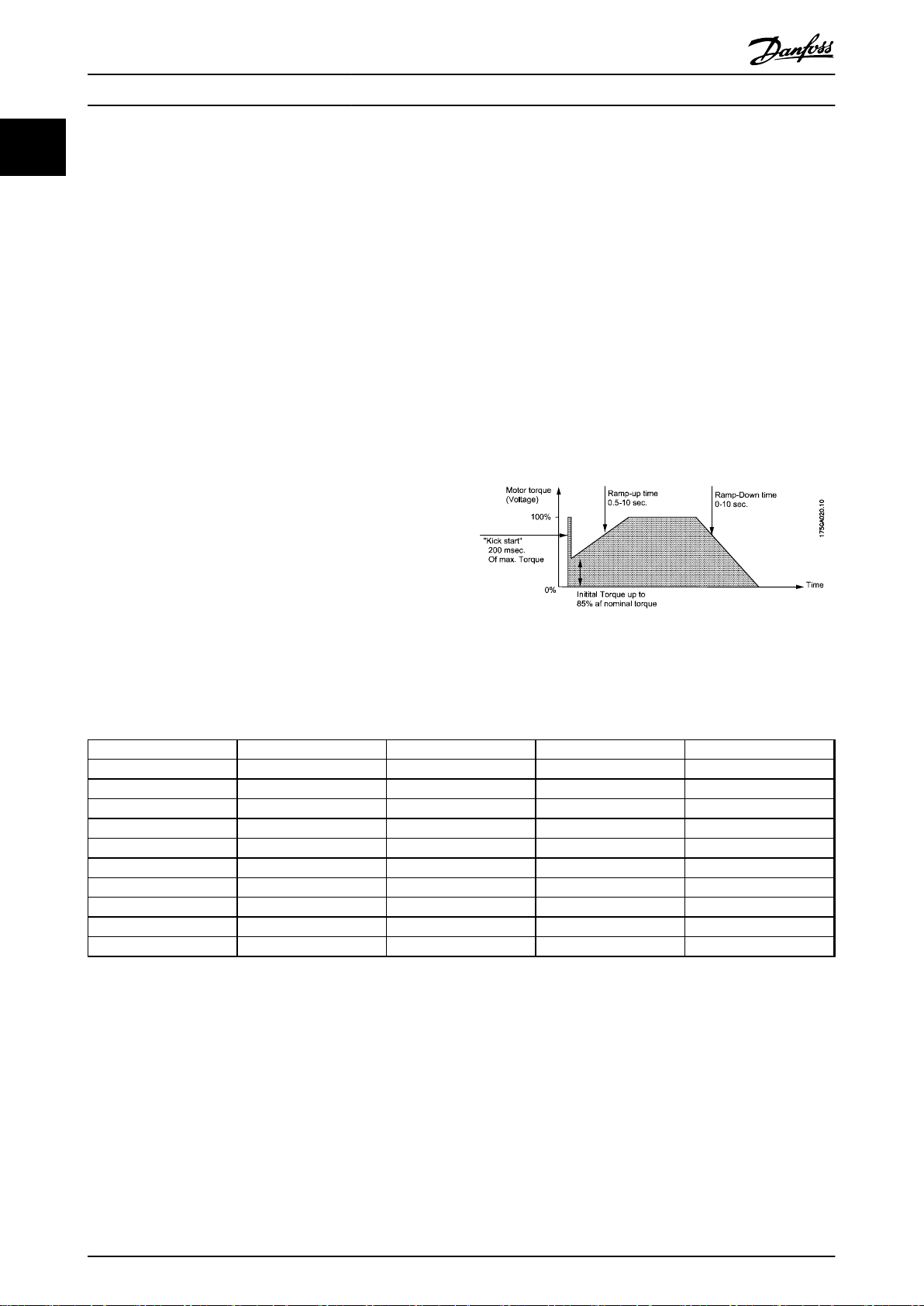
1.3.2
Ramp up
During ramp-up the controller will gradually increase the
voltage to the motor until it reaches full line voltage. The
motor speed will depend on the actual load on the motor
shaft. A motor with little or no load will reach full speed
before the voltage has reached its maximum value. The
actual ramp time is digitally calculated and will not be
influenced by other settings, net frequency or load
variations.
Initial torque
The initial torque is used to set the initial starting voltage.
This way it is possible to adapt the controller to an
application requiring a higher starting torque. In some
cases the application will need a high break-away torque.
Here, the initial starting torque level can be combined with
a kick start function. The kick start is a period of 200 ms
where the motor receives full voltage.
Soft stop
During ramp-down the controller will gradually reduce the
voltage to the motor thus reducing the torque and
current. As a consequence the motor speed will fade off.
The soft stop feature is advantageous to avoid liquid
hammering and cavitation on pumps, and to avoid goods
tilting on conveyors.
LED Status Indication
1.3.3
LED 1
LED 2
Stand
by
Table 1.8
RampupFull on Ramp down Line on
load error
4 MG12A202 - VLT® is a registered trademark
Page 5

All about MCD 100 MCD 100 Design Guide
1.3.4 Wiring
Illustration 1.2 MCD 100 - 007 / MCD 100 - 011
Adjustments
1.3.5
Fuses and short circuit protection
1.3.6
1 1
MCD 100 provides Timed Voltage Ramp up. This means
that the motor voltage is gradually ramped up to full line
voltage according to the time set by the rotary switch.
To avoid soft starter damage, proper settings of initial
torque level and ramp up time must be considered. It is
important to ensure that the motor is accelerated to full
speed before the soft starter is in full on mode.
Setting the initial torque level:
1. Set ramp up time to max.
2. Set initial torque switch to min.
3. Apply control signal for a few seconds. If the
motor does not rotate immediately increase the
initial torque level with on step and try again.
Repeat until the motor starts to rotate
immediately after control signal is applied.
Setting the ramp up time:
1. Set ramp up time to max.
2. Decrease the ramp up time until mechanical
surge is observed.
3. Increase ramp up time with one step.
In case of short circuits normal fuses can be used to
protect the installation – but not the soft starter. The
following table lists data for the selection of normal fuses.
MCD 100-001 Protection max 25 A gL/gG
MCD 100-007 Protection max 50 A gL/gG
MCD 100-011 Protection max 80 A gL/gG
Table 1.9
Semiconductor fuses may be used with MCD 100 soft start
controllers. Use of semiconductor fuses will protect the
SCR’s in case of short circuits and reduce the potential of
SCR damage due to transient overload currents. When
selecting semiconductor fuses ensure that the fuse has a
lower total clearing I2t rating than the SCR (see data in the
following table), and that the fuse can carry the start
current for the actual start duration.
MCD 100
MCD 100-001 72
MCD 100-007 1800
MCD 100-011 6300
Table 1.10
SCR I2t
(A2s)
MG12A202 - VLT® is a registered trademark 5
Page 6

All about MCD 100 MCD 100 Design Guide
11
1.3.7 Dimensions
Illustration 1.3 MCD 100 - 001
Illustration 1.4 MCD 100 - 007
Illustration 1.5 MCD 100 - 011
6 MG12A202 - VLT® is a registered trademark
Page 7

All about MCD 100 MCD 100 Design Guide
1.3.8 Operating at High Temperatures
Ambient temperature
40°C 3 A 15 A 25 A
50°C 2.5 A* 12.5 A 20 A
60°C 2.0 A* 10 A 17 A
Table 1.11
* Minimum 10 mm side clearance between products
Ambient temperature
40°C 15 A (100 % duty-cycle) 25 A (100 % duty-cycle)
50°C 15 A (80 % duty-cycle) 25 A (80 % duty-cycle)
60°C 15 A (65 % duty-cycle) 25 A (65 % duty-cycle)
Table 1.12
MCD 100 - 001 MCD 100 - 007 MCD 100 - 011
MCD 100 - 007 MCD 100 - 011
Continous current
Duty-cycle rating (15 min. max. on-time)
1.3.9 Over Heat Protection
If required the controller can be protected against
overheating by inserting a thermostat in the slot on the
right-hand side of the controller.
1 1
Order: UP 62 thermostat 037N0050
Depending on the application the thermostat can be
connected in series with the control circuit of the main
contactor. When the temperature of the heat sink exceeds
90° C the main contactor will be switched OFF. A manual
reset is necessary to restart this circuit.
For wiring connections see 1.4 Application Examples.
Illustration 1.6
1.3.10
The controller is designed for vertical mounting. If the
controller is mounted horizontally the load current must
be reduced by 50%.
Mounting Instructions
The controller needs no side clearance.
Clearance between two vertical mounted controllers must
be minimum 80 mm (3.15”).
MG12A202 - VLT® is a registered trademark 7
Page 8

All about MCD 100 MCD 100 Design Guide
11
Clearance between controller and top and bottom walls
must be minimum 30 mm (1.2”).
Illustration 1.7
When the contactor C1 is switched to the OFF-State, the
motor will be switched off instantaneously.
In this application the contactor will have no load during
making operation. The contactor will carry and break the
nominal motor current.
1.4 Application Examples
1.4.1 Overheat protection
Example 1
The thermostat can be connected in series with the control
input of the soft starter. When the temperature of the heat
sink exceedes 90°C the soft starter will be switched OFF.
NOTE
When the temperature has dropped approximately 30°C
the controller will automatically be switched On again. This
is not acceptable in some applications.
Example 2
The thermostat is connected in series with the control
circuit of the main contactor. When the temperature of the
heat sink exceeds 90°C the main contactor will be
switched OFF. This circuit requires manual reset to restart
the motor.
Illustration 1.8
1.4.2 Line Controlled Soft Start
When the contractor C1 is switched to the ON-State, the
soft starter will start the motor, according to the settings
of the Ramp-up time and Initial torque adjustments.
8 MG12A202 - VLT® is a registered trademark
Page 9

All about MCD 100 MCD 100 Design Guide
1 1
Illustration 1.9
Input Controlled Soft Start
1.4.3
When the control voltage is applied to A1 - A2, the MCD
soft starter will start the motor, according to the settings
of the Ramp-up time and Initial torque adjustments.
When the control voltage is switched OFF, the motor will
be soft stopped according to the settings of the Rampdown time adjustments.
To switch off instantaneously set the Ramp-down time to
0.
Illustration 1.10
MG12A202 - VLT® is a registered trademark 9
 Loading...