

Page 1
Data sheet
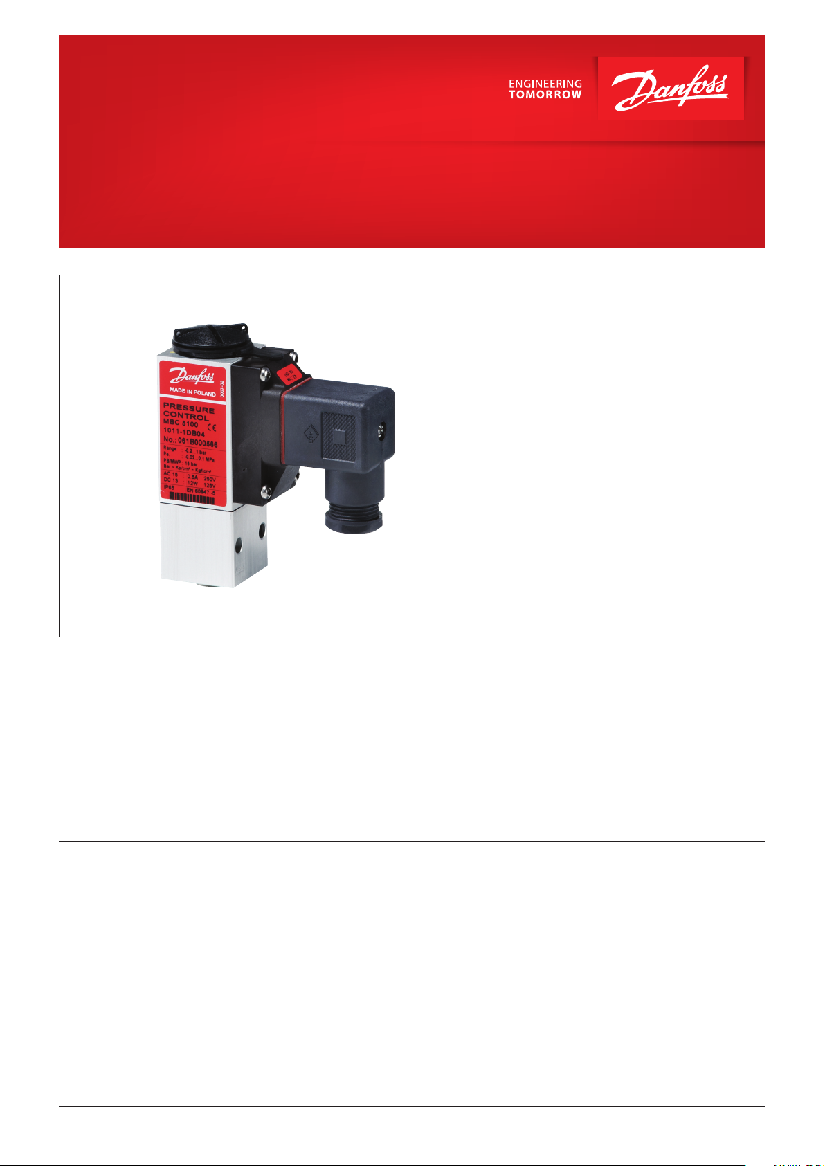
Heavy duty pressure switch
MBC 5000 and MBC 5100
MBC pressure switches are used in industrial and
marine applications where space and reliability
are the most important features.
MBCs are compact pressure switches, designed
according to our block design to survive in the
harsh conditions known from machine rooms
onboard ships.
MBCs have high vibration resistance and
MBC 5100 features all common marine approvals.
The fixed, but low differential guarantees
accurate monitoring of critical pressures.
MBV test valves can be delivered as standard
option for MBC.
Features
Approvals
Ship approvals,
Type MBC 5100
• Designed for use in severe industrial,
environments,
• High vibration stability
• Part of the Danfoss block system, consisting
of MBC pressure controls, MBS pressure
transmitters and MBV test valves
EN 60947-1
EN 60947-4-1
EN 60947-5-1
Lloyd’s Register, LR
Det Norske Veritas and Germanischer Lloyd, DNV GL
Registro Italiano Navale, RINA
Nippon Kaiji Kyokai, NKK
• MBC 5100 with all major ship approvals,
• High repeatability,
• Optimal compact design for machine
building purposes
• Intended for alarm indication, shut down,
control and diagnostics in many
applications - motors, gears, thrusters,
pumps, filters, compressors etc.
China Compulsory Certificate, CCC
Bureau Veritas, BV
American Bureau of Shipping, ABS
Korean Register of Shipping, KR
Russian Maritime Register of Shipping, RMRS
China Classification Society, CCS
© Danfoss | DCS (rm) | 2019.09
Note: For stainless steel types only DNV GL and BV approvals are available.
IC.PD.P10.4A.02 | 1
Page 2
Data sheet | Heavy duty pressure switch, type MBC 5000 and MBC 5100
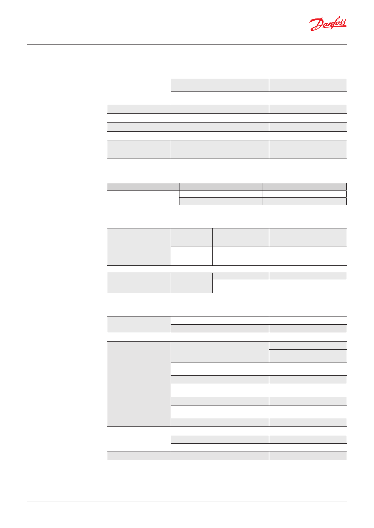
Technical data
Performance
Bellows versions
Repeatability
Max. switch frequency 10/min (0.16 Hz)
Differential See page 4
Permissible operating pressure See page 4
Burst pressure See page 4
Life time
Diaphragm versions
Piston versions
Mechanical for diaphragm and bellows
Mechanical for piston type
Electrical at max. contact load
± 0.2 % FS (typ.)
± 0.5 % FS (max.)
± 0.5 % FS (typ.)
± 1.0 % FS (max.)
± 1.0 % FS (typ.)
± 1.0 % FS (max.)
> 400,000 cycles
>1 million cycles
> 100,000 cycles
Electrical specifications
Switch SPDT
Contact load
AC 15 0.5 A, 250 V
DC 13 12 W, 125 V
Environmental conditions
Operation
Temperature
Transport
Enclosure IP65, EN 60529
Vibration stability Sinusoidal
Bellows versions
Diaphragm versions
Piston versions
Bellows versions
Diaphragm versions
Piston versions
20 g, 25 – 2 kHz EN 60068-2-6
Piston type 4.4 g,
25 – 200 Hz
-40 – 85 °C
-10 – 85 °C
-40 – 85 °C
-50 – 85 °C
-50 – 85 °C
-40 – 85 °C
IEC 60068-2-27
Mechanical characteristics
Pressure connection
Electrical connection Plug DIN 43650, Pg 9 / Pg 11 / Pg 13.5
Wetted parts material
Enclosure material
Net weight 0.25 kg
Standard G ¼ female (ISO 228-1) or flange
Option See specification form, page 4
Anodized AIMgSi1, AW-6082T6
Housing
Bellows
Diaphragm FKM
Piston
O-ring NBR
Hole plug
(flange version)
Seal (piston version) Turcon T05
Housing Anodized AIMgSi1, AW-6082T6
Plug fixture Glass filled polyamid, PA 6.6
Contact system Silver (AG) microprofile
Stainless steel 1.4306 (18/8),
acc. to EN10088-3
Stainless steel 1.4306 (18/8),
acc. to EN10088-2
Stainless steel 1.4028 (3H13),
acc. to EN10088-2
Nickel plated brass or zinc plated
steel
© Danfoss | DCS (rm) | 2019.09
IC.PD.P10.4A.02 | 2
Page 3

Data sheet | Heavy duty pressure switch, type MBC 5000 and MBC 5100
Electrical connection
Out NO
Out NC
Adjustment
Out NO
Out NC
InIn
Danfoss
93Z19.11
Input
Input
Normally closed (NC)
Normally closed (NC)
Normally open (NO)
Normally open (NO)
Connected to enclosure of pressure control
Connected to enclosure
of pressure control
Mechanical connection
Mechanical difference
One full turn (360°) of MBC setting screw is approx. equal to 7% of the setting range
Thread
Flange connection on MBV 5000 Test Valve
Not applicable for piston type
How to choose To achieve the best operating conditions for MBC
pressure controls, it is recommended to apply the
following rules of thumb.
Choose:
• The MBC type/types which meet the demands
for the operating pressure
• The MBC version with the lowest possible
setting range
© Danfoss | DCS (rm) | 2019.09
• A diaphragm type, if pressure peaks and
pulsations occur in the system (if possible)
• Bellows type, if low differential is needed
• Piston type for high pressure
IC.PD.P10.4A.02 | 3
Page 4

Data sheet | Heavy duty pressure switch, type MBC 5000 and MBC 5100
Ordering
standard types
Type:
LP
Low pressure /
HP
High pressure
Setting
range
Pe
[bar]
Diff. at
min.
range 1)
Pe
[bar]
Diff. at
max.
range 1)
Pe
[bar]
Permissible
operating
pressure
Pe
[bar]
Min. burst
pressure
Pe
[bar]
Type
designation
MBC 5000- /
MBC 5100-
MBC 5100
Ship
approved
Code no.
LP bellows -0.20 – 1.00 0.30 0.45 15 30 1011-1DB04 061B000566
LP bellows -0.20 – 4.00 0.30 0.45 15 30 1211-1DB04 061B000466 2)
LP bellows -0.20 – 10.00 0.40 0.60 15 30 1411-1DB04 061B000266 2)
LP bellows -0.20 – 10.00 0.40 0.60 15 30 1411-1CB04 061B000066
LP bellows 0.50 – 3.00 0.25 0.30 15 30 2011-1DB04 061B002966
LP bellows 1.00 – 6.00 0.30 0.45 15 30 2211-1DB04 061B000766
HP bellows 5.00 – 30.00 0.90 2.00 45 90 3421-1DB04 061B000366 2)
LP diaphragm 0.50 – 3.00 0.50 0.80 150 300 2031-1DB04 061B101766
LP diaphragm 1.00 – 6.00 1.00 2.50 150 300 2231-1DB04 061B100966
LP diaphragm 1.00 – 10.00 1.00 2.50 150 300 2431-1DB04 061B100466 2)
LP diaphragm 5.00 – 20.00 1.00 2.50 150 300 3231-1DB04 061B100266 2)
LP diaphragm 5.00 – 25.00 1.00 2.50 150 300 3331-1DB04 061B102466
HP diaphragm 5.00 – 40.00 2.00 7.00 150 300 3641-1DB04 061B100566 2)
HP diaphragm 10.00 – 100.00 4.00 12.00 150 300 4241-1DB04 061B100366 2)
HP piston 16.00 – 160.00 15.00 30.00 600 1200 5251-1CB04 061B510066
HP piston 25.00 – 250.00 20.00 40.00 600 1200 5451-1CB04 061B510166
HP piston 40.00 – 400.00 20.00 50.00 600 1200 5651-1CB04 061B510266
1
)
Max value, all values lower or equal are correct
2
)
Preferred versions
Ordering stainless
steel types
Ordering
customized types
Type:
LP
Low pressure /
HP
High pressure
Setting
range
Pe
[bar]
Diff. at
min.
range 1)
Pe
[bar]
Diff. at
max.
range 1)
Pe
[bar]
Permissible
operating
pressure
Pe
[bar]
Min. burst
pressure
Pe
[bar]
Type
designation
MBC 5000- /
MBC 5100-
MBC 5100
Ship
approved
Code no.
LP bellows -0.20 – 10.00 0.40 0.60 15 30 1411-1DB04S 061B025066
LP bellows -0.20 – 4.00 0.30 0.45 15 30 1211-1DB04S 061B025166
LP bellows -0.20 – 10.00 0.40 0.60 15 30 1411-2DB04S 061B025266
LP bellows -0.20 – 4.00 0.30 0.45 15 30 1211-2DB04S 061B025366
1
)
Max value, all values lower or equal are correct
MBC 5000-
MBC 5100-
Setting range
-0.2 – 1 bar.......................................... 1 0
-0.2 – 4 bar.......................................... 1 2
-0.2 – 10 bar ....................................... 1 4
0.5 – 3 bar ........................................... 2 0
1 – 6 bar .............................................. 2 2
1 – 10 bar ............................................ 2 4
2 – 6 bar .............................................. 2 6
5 – 0 bar .............................................. 3 2
5 – 25 bar ............................................ 3 3
5 – 30 bar ............................................ 3 4
5 – 40 bar ............................................ 3 6
10 – 100 bar ....................................... 4 2
16 – 160 bar ....................................... 5 2
25 – 250 bar ....................................... 5 4
40 – 400 bar ....................................... 5 6
Others .................................................. x x
Type
Low pressure bellows (-0.2 – 10 bar) ....................... 1
High pressure bellows (2 – 30 bar) ........................... 2
Low pressure diaphragm (0.5 – 25 bar) .................. 3
High pressure diaphragm (5 – 100 bar) .................. 4
High pressure piston (40 – 400 bar) ......................... 5
Pressure connection
C A 0 5 .......... M10x1 female
C B 0 4 .......... G ¼ female
D A 0 5 .......... M10x1 female with flange connection
D B 0 4 .......... G ¼ female with flange connection
x x x x .......... Others
Electrical connection
0 .................................................................. No plug (DIN 43650 A)
1 .................................................................. Pg 11 plug (DIN 43650 A)
2 .................................................................. Pg 13.5 plug (DIN 43650 A)
3 .................................................................. Pg 9 plug (DIN 43650 A)
x .................................................................. Others
Microswitch
1 ..................................................................................... 0.5 A, 250 V (AC 15)
12 W, 125 V (DC 13)
x ..................................................................................... Others
......... 6082 (AIMgSi1) version
.......... Stainless steel (1.4306)
S
version
© Danfoss | DCS (rm) | 2019.09
IC.PD.P10.4A.02 | 4
Page 5

Data sheet | Heavy duty pressure switch, type MBC 5000 and MBC 5100
Dimensions [mm]
and weights [kg]
93
Danfoss
93Z05.15
Net weight: 0.25 kg
93
Danfoss
93Z14.18
Net weight: 0.25 kg
© Danfoss | DCS (rm) | 2019.09
IC.PD.P10.4A.02 | 5
Page 6

61B41.10
61B40.10
Accessories
Part Description Code number:
Pulse snubber
Danfoss
61B42.10
Male, G¼A, length 20 mm 061B400166
Pulse snubber
Danfoss
Male, G¼A, length 34 mm 061B400266
Pulse snubber
Danfoss
For flange connection 061B722166
© Danfoss | DCS (rm) | 2019.09
IC.PD.P10.4A.02 | 6
 Loading...