

Page 1
Data sheet
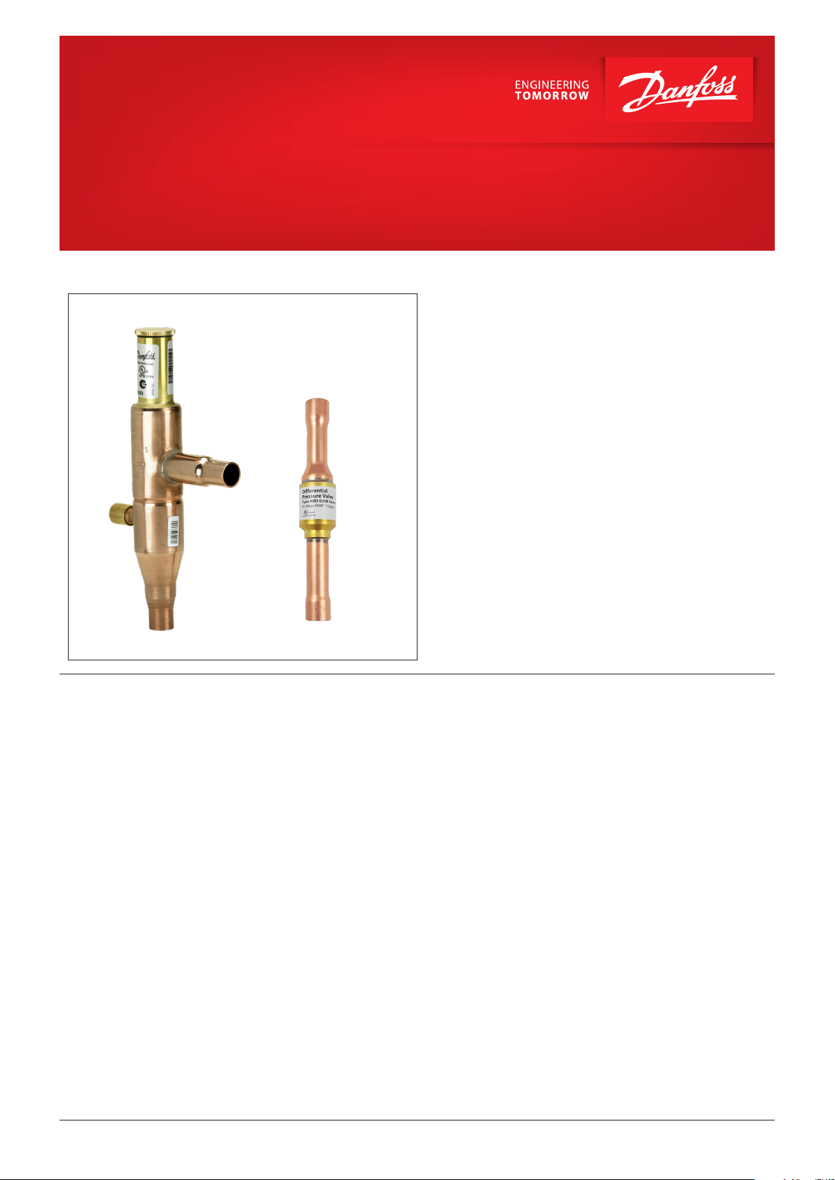
Condensing pressure regulator, type KVR
Differential pressure valve, type NRD
Regulating system KVR and NRD is used to
maintain a constant and sufficiently high
condenser and receiver pressure in refrigeration
and air conditioning plant with air-cooled
condensers.
KVR can also be used together with receiver
pressure regulator, type KVD.
Features • Accurate, adjustable pressure regulation
• Wide capacity and operating range
• Pulsation damping design
• Stainless steel bellows
• Compact angle design for easy installation in
any position
• “Hermetic” brazed construction
• 1⁄4 in. Schrader valve for pressure gauge
connection
• Available with flare and ODF solder
connections
• KVR 12 - KVR 22 and NRD: May be used in the
following EX range: Category 3 (Zone 2)
© Danfoss | DCS (bh) | 2019.09
AI251086497566en-000901 | 1
Page 2
Data sheet | Condensing pressure regulator, type KVR and differential pressure valve, type NRD
Approvals
Technical data
Ordering
UL LISTED, file SA7200
EAC
R22, R32**, R1270*, R134a, R290*, R404A, R407A, R407C,
R407F, R407H, R410A**, R448A, R449A, R449B, R450A, R452A,
Refrigerants
Adjustment range
Maximum working pressure
Maximum test pressure
Medium temperature range
P-band
Minimum opening pressure differential for NRD Start opening: Δp = 1.4 bar
KVR 12 - KVR 22 is evaluated for R290, R454A, R454C,
R455A, R600, R600a, R1234ze(E), R1270 by ignition
source assessment in accordance with standard
EN13463-1.
R452B**, R454A*, R454B**, R454C*, R455A*, R507, R513A,
R515B, R516A, R600*, R600a*, R1233zd(E)**, R1234ze(E)*,
R1234yf**
*KVR 12 - KVR 22 and NRD only
**NRD only
5 – 17.5 bar
Factory setting = 10 bar
KVR: PS/MWP = 28 bar
NRD: PS/MWP = 49 bar
KVR: Pe = 31 bar
NRD: Pe = 81 bar
KVR: -45 – 130 °C,
NRD: -50 – 155 °C
KVR 12 – 22 = 6.2 bar
KVR 28 – 35 = 5 bar
For complete list of approved refrigerants,
visit http://store.danfoss.com/ and search for
individual code numbers, where refrigerants are
listed as part of technical data.
NRD is evaluated for R32, R1270, R290, R452B, R454A,
R454B, R454C R455A, R600, R600a, R1233zd(E),
R1234ze(E), R1234yf by ignition source assessment in
accordance with standard EN13463-1.
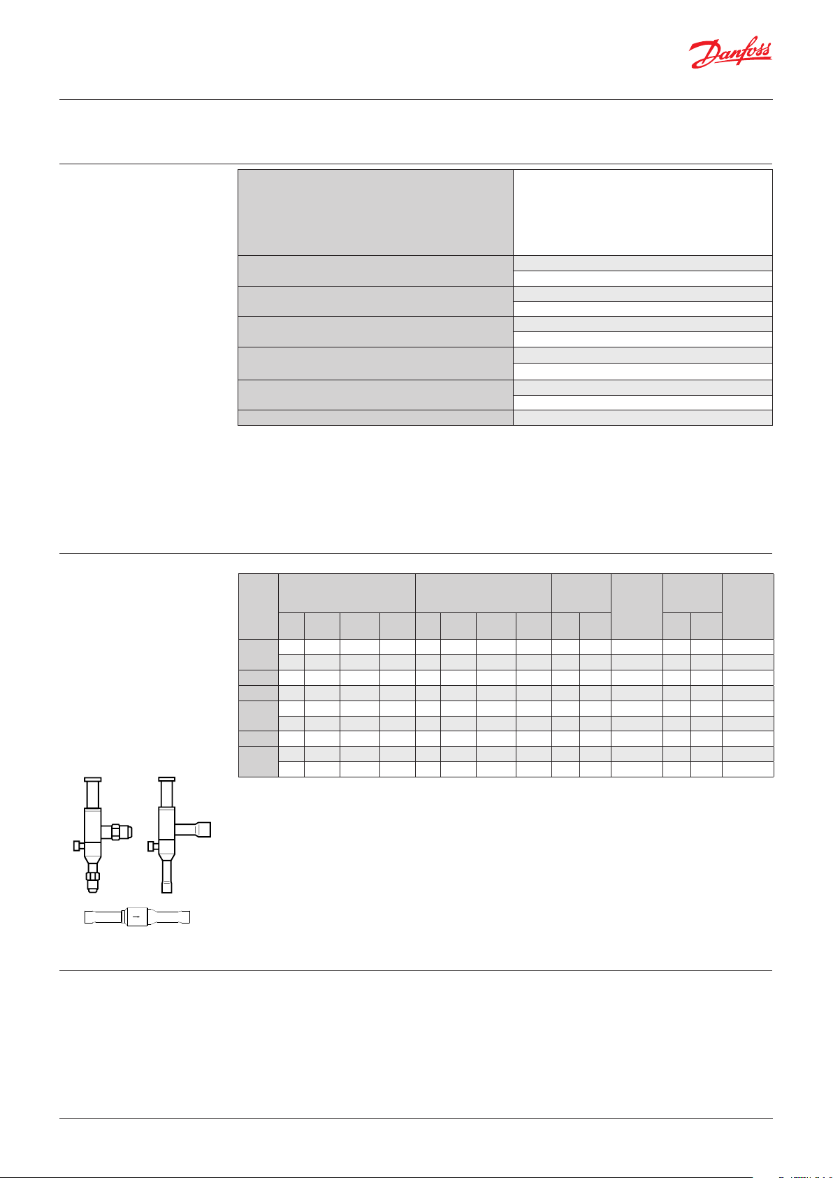
KVR 12, KVR 15, KVR 22, KVR 28, KVR 35, NRD
Rated liquid capacity 1)
(Evaporator capacity)
Type
R22 R134a
50.4 47.3 36.6 54.4 13.2 11.6 12.0 14.31⁄2 12 034L00911⁄2 – 034L0093
KVR 12
50.4 47.3 36.6 54.4 13.2 11.6 12.0 14.3 – – – – 12 034L0096
KVR 15 50.4 47.3 36.6 54.4 13.2 11.6 12.0 14.35⁄8 16 034L00925⁄8 16 034L0097
KVR 22 50.4 47.3 36.6 54.4 13.2 11.6 12.0 14.3 – – –
129 121 93.7 139.3 34.9 30.6 34.9 37.7 – – – 1
KVR 28
129 121 93.7 139.3 34.9 30.6 34.9 37.7 – – – – 28 034L0099
KVR 35 129 121 93.7 139.3 34.9 30.6 34.9 37.7 – – – 1 3⁄8 35 034L0100
NRD
The connection dimensions chosen must not be too small, since gas velocities in excess of 40 m / s at the inlet of the regulator can give
flow noise.
1
) Rated capacity is based on:
To select the product for other conditions or refrigerants, use Danfoss Coolselector®2.
2
) KVR are delivered without flare nuts. Separate flare nuts can be delivered:
– – – – – – – – – – –
– – – – – – – – – – – – 12 020B1136
– evaporating temperature te = -10 °C
– condensing temperature tc = 30 °C
– pressure drop across the valve
Δp = 0.2 bar for liquid capacity
Δp = 0.4 bar for hot gas capacity
– offset = 3 bar
– 1⁄2 in / 12 mm, code no. 011L1103
– 5⁄8 in / 16 mm, code no. 011L1167
[kW]
R404A/
R507
R407C R22 R134a
Rated hot gas 1)
(Evaporator capacity)
[kW]
R404A/
R507
Flare
connect. 2)
R407C [in] [mm] [in] [mm]
Code no.
Solder
Connect.
7
⁄8 22 034L0094
1
⁄8 – 034L0095
1
⁄2 – 020B1132
Code no.
REACH requirements
© Danfoss | DCS (bh) | 2019.09
All Danfoss products fulfill the requirements in REACH.
One of the obligations in REACH is to inform customers about
presence of Candidate list substances if any, we hereby inform
you about one substance on the candidate list:
an O-ring used in this product contains Diisopentylphthalat
(CAS no: 605-50-5) in a concentration above 0.1% w/w.
AI251086497566en-000901 | 2
Page 3
Data sheet | Condensing pressure regulator, type KVR and differential pressure valve, type NRD
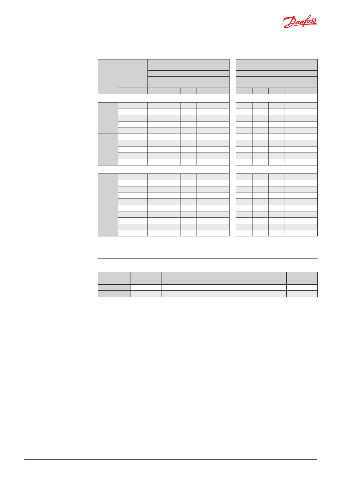
Liquid capacity
Max. regulator capacity Qe 1)
Liquid capacity in [kW]
Condensing
Type
KVR 12
KVR 15
KVR 22
KVR 28
KVR 35
KVR 12
KVR 15
KVR 22
KVR 28
KVR 35
1
) The capacities are based on:
temperature t
– Evaporating temperature te= -10 °C
– For other evaporating temperatures see table below
c
[°C] 0.1 0.2 0.4 0.8 1.6 0.1 0.2 0.4 0.8 1.6
10 23.7 33.5 47.4 67.0 94.8 42.5 60.2 85.1 120.4 170.5
20 21.8 30.8 43.6 61.7 87.3 39.2 55.4 78.4 110.9 157.0
30 19.8 28.1 39.7 56.2 79.4 35.6 50.4 71.3 100.9 142.9
40 17.8 25.2 35.6 50.4 71.3 32.0 45.3 64.0 90.6 128.3
50 15.7 22.2 31.4 44.4 62.9 28.2 39.9 56.4 79.9 113.1
10 60.5 85.6 121.1 171.2 242.3 108.9 154.0 217.8 308.2 436.2
20 55.7 78.8 111.4 157.6 223.0 100.2 141.8 200.6 283.8 401.7
30 50.7 71.7 101.4 143.4 202.9 91.2 129.0 182.5 258.2 365.5
40 45.9 64.3 91.0 128.7 182.1 81.9 115.8 163.9 231.8 328.2
50 40.1 58.8 80.3 113.6 160.7 72.2 102.1 144.4 204.4 289.3
10 22.8 32.3 45.6 64.6 91.3 40.7 57.5 81.4 115.0 163.0
20 20.8 29.4 41.6 58.8 83.2 37.1 52.5 74.2 105.0 149.0
30 18.7 26.5 37.4 53.0 74.9 33.4 47.3 66.9 94.7 134.0
40 16.6 23.5 33.2 47.0 66.5 29.7 42.0 59.4 84.1 119.0
50 14.5 20.5 29.0 41.0 58.0 25.9 36.6 51.8 73.3 104.0
10 58.3 82.4 117.0 165.0 233.0 104.0 147.0 208.0 295.0 418.0
20 53.1 75.1 106.0 150.0 213.0 94.9 134.0 190.0 269.0 361.0
30 47.8 67.6 95.7 135.0 191.0 85.5 121.0 171.0 242.0 343.0
40 42.5 60.0 84.9 120.0 170.0 76.0 108.0 152.0 215.0 305.0
50 37.0 52.3 74.0 105.0 148.0 66.3 93.7 133.0 188.0 266.0
(Evaporator capacity)
Pressure drop across valve ∆
Liquid capacity in [kW]
(Evaporator capacity)
Offset 1.5 bar Offset 3 bar
[bar]
p
Pressure drop across valve ∆
[bar]
R22 R22
R134 a R134 a
p
Correction factors for evaporating temperature t
t
e
[°C]
R22 1.09 1.05 1.02 1.0 0.98 0.96
R134a 1.14 1.09 1.04 1.0 0.96 0.93
Plant capacity x correction factor = table capacity
-40 -30 -20 -10 0 10
e
© Danfoss | DCS (bh) | 2019.09
AI251086497566en-000901 | 3
Page 4

Data sheet | Condensing pressure regulator, type KVR and differential pressure valve, type NRD
Liquid capacity
(continued)
Max. regulator capacity Qe 1)
Liquid capacity in [kW]
Condensing
Type
KVR 12
KVR 15
KVR 22
KVR 28
KVR 35
KVR 12
KVR 15
KVR 22
KVR 28
KVR 35
1
) The capacities are based on:
temperature t
– Evaporating temperature te= -10 °C
– For other evaporating temperatures see table below
c
[°C] 0.1 0.2 0.4 0.8 1.6 0.1 0.2 0.4 0.8 1.6
10 18.4 25.9 36.8 52.0 73.5 32.9 46.4 65.6 92.9 131.3
20 16.4 23.2 32.9 46.5 65.7 29.4 41.6 58.8 83.2 117.6
30 14.5 20.5 29.0 41.0 58.0 25.9 36.6 51.8 73.3 103.7
40 12.9 17.6 25.0 35.4 50.1 22.4 31.6 44.7 63.3 89.7
50 10.5 14.9 21.0 29.7 42.1 18.8 26.6 37.6 53.2 75.4
10 46.9 66.3 93.8 132.3 188.0 84.0 118.7 168.0 237.3 337.1
20 42.0 59.3 83.9 118.7 168.0 75.2 106.1 150.2 213.2 301.4
30 37.0 52.3 73.9 104.6 148.1 66.3 93.7 132.3 188.0 265.7
40 31.9 45.2 63.8 90.3 128.1 57.2 81.0 114.5 161.7 228.9
50 26.9 37.9 53.7 75.9 107.0 48.1 68.0 96.2 136.5 193.2
10 25.6 36.2 51.2 72.6 102.3 45.9 65.0 91.9 130.0 184.1
20 23.5 33.2 47.1 66.6 94.3 42.3 59.8 84.7 119.8 169.6
30 21.4 30.3 42.9 60.7 85.7 38.4 54.4 77.0 109.0 154.3
40 19.4 27.5 38.8 55.0 77.7 34.9 49.4 69.8 98.8 139.8
50 17.3 24.4 34.5 48.8 69.2 31.0 43.9 62.0 87.9 124.4
10 65.3 92.4 130.7 184.9 261.7 117.6 166.3 235.2 332.9 471.1
20 60.1 85.1 120.3 170.2 240.8 108.2 153.1 216.6 306.5 433.8
30 54.5 77.4 109.5 154.9 219.1 98.5 139.3 197.1 278.9 394.7
40 50.0 70.1 99.2 140.3 198.5 89.3 126.2 178.7 252.7 357.7
50 44.1 62.5 88.3 124.9 176.8 79.4 112.3 158.8 224.8 318.2
(Evaporator capacity)
Pressure drop across valve ∆
Liquid capacity in [kW]
(Evaporator capacity)
Offset 1.5 bar Offset 3 bar
[bar]
p
Pressure drop across valve ∆
[bar]
R404A / R507 R404A / R507
R407C R407C
p
Correction factors for evaporating temperature t
t
e
[°C]
R404A / R507 1.18 1.11 1.05 1.0 0.95 0.92
R407C 1.12 1.08 1.04 1.0 0.97 0.93
Plant capacity x correction factor = table capacity
-40 -30 -20 -10 0 10
e
© Danfoss | DCS (bh) | 2019.09
AI251086497566en-000901 | 4
Page 5

Data sheet | Condensing pressure regulator, type KVR and differential pressure valve, type NRD
Hot gas capacity
Max. regulator capacity Qe 1)
Hot gas capacity in [kW]
Condensing
Type
KVR 12
KVR 15
KVR 22
KVR 28
KVR 35
KVR 12
KVR 15
KVR 22
KVR 28
KVR 35
1
) The capacities are based on:
temperature t
– Evaporating temperature te= -10 °C
– For other evaporating temperatures see table below
c
[°C] 0.1 0.2 0.4 0.8 1.6 0.1 0.2 0.4 0.8 1.6
10 3.3 4.6 6.4 8.8 11.8 6.0 8.4 11.8 16.3 22.2
20 3.5 5.0 6.9 9.6 13.0 6.3 8.9 12.5 17.4 23.9
30 3.7 5.3 7.4 10.3 14.4 6.6 9.4 13.2 18.4 25.4
40 3.9 5.5 7.8 10.9 15.0 6.9 9.8 13.7 19.3 26.7
50 4.1 5.7 8.1 11.3 15.7 7.1 10.1 14.2 20.0 27.7
10 8.5 11.9 16.6 22.8 30.3 15.8 22.2 31.1 43.2 58.7
20 9.1 12.8 17.9 24.8 33.5 16.7 23.5 33.1 46.1 63.1
30 9.7 13.6 19.1 26.6 36.3 17.6 24.8 34.9 48.7 67.2
40 10.2 14.3 20.1 28.1 38.7 18.3 25.9 36.4 51.0 70.6
50 10.5 14.9 20.9 29.2 40.4 18.9 26.6 37.5 52.6 73.2
10 2.9 4.0 5.6 7.6 9.7 5.4 7.6 10.7 14.7 19.6
20 3.1 4.3 6.0 8.2 10.8 5.6 7.9 11.1 15.4 20.8
30 3.2 4.5 6.3 8.8 11.7 5.8 8.2 11.6 16.1 21.9
40 3.4 4.7 6.6 9.2 12.5 6.0 8.5 11.9 16.6 22.8
50 3.4 4.8 6.8 9.5 13.0 6.1 8.6 12.1 16.9 23.3
10 7.5 10.5 14.5 19.6 25.0 14.4 20.2 28.2 38.8 51.8
20 7.9 11.1 15.5 21.2 27.8 15.0 21.0 29.5 40.8 55.0
30 8.4 11.8 16.4 22.6 30.2 15.5 21.8 30.6 42.5 57.9
40 8.7 12.2 17.1 23.7 32.1 15.9 22.4 31.5 43.9 60.3
50 8.9 12.5 17.6 24.5 33.5 16.1 22.7 32.0 44.7 61.7
(Evaporator capacity)
Pressure drop across valve ∆
Hot gas capacity in [kW]
(Evaporator capacity)
Offset 1.5 bar Offset 3 bar
[bar]
p
Pressure drop across valve ∆
[bar]
R22 R22
R134 a R134 a
p
Correction factors for evaporating temperature t
t
e
[°C]
R22 1.09 1.05 1.02 1.0 0.98 0.96
R134a 1.14 1.09 1.04 1.0 0.96 0.93
Plant capacity x correction factor = table capacity
-40 -30 -20 -10 0 10
e
© Danfoss | DCS (bh) | 2019.09
AI251086497566en-000901 | 5
Page 6

Data sheet | Condensing pressure regulator, type KVR and differential pressure valve, type NRD
Hot gas capacity
(continued)
Max. regulator capacity Qe 1)
Hot gas capacity in [kW]
Condensing
Type
KVR 12
KVR 15
KVR 22
KVR 28
KVR 35
KVR 12
KVR 15
KVR 22
KVR 28
KVR 35
1
) The capacities are based on:
temperature t
– Evaporating temperature te= -10 °C
– For other evaporating temperatures see table below
c
[°C] 0.1 0.2 0.4 0.8 1.6 0.1 0.2 0.4 0.8 1.6
10 3.2 4.5 6.3 8.6 11.7 5.8 8.1 11.3 15.8 21.6
20 3.4 4.7 6.6 9.2 12.4 6.1 8.4 11.8 16.5 22.7
30 3.5 4.9 6.8 9.5 13.0 6.1 8.5 12.0 16.8 23.2
40 3.5 4.9 6.8 9.6 13.1 6.1 8.6 12.1 16.9 23.2
50 3.5 4.9 6.8 9.6 13.1 6.1 8.6 12.1 16.9 23.2
10 8.3 11.7 16.2 22.3 30.0 15.8 22.2 31.1 43.2 58.7
20 8.7 12.2 17.1 23.7 32.2 16.7 23.5 33.1 46.1 63.1
30 8.9 12.5 17.6 24.4 33.5 17.6 24.8 34.9 48.7 67.2
40 9.0 12.6 17.8 24.8 33.0 18.3 25.9 36.4 51.0 70.6
50 9.0 12.6 17.8 24.8 33.5 18.9 26.6 37.5 52.6 73.2
10 3.6 5.0 6.9 9.5 12.8 6.5 9.1 12.7 17.6 24.0
20 3.8 5.4 7.5 10.4 14.0 6.8 9.6 13.5 18.8 25.8
30 4.0 5.8 8.0 11.1 15.5 7.1 10.2 14.3 19.9 27.4
40 4.2 6.0 8.5 11.9 16.4 7.5 10.7 14.9 21.0 29.1
50 4.5 6.3 8.9 12.4 17.3 7.8 11.1 15.6 22.0 30.5
10 9.2 12.9 17.9 24.7 32.7 17.1 24.0 33.6 46.7 63.4
20 9.8 13.8 19.3 26.8 36.2 18.0 25.4 35.7 49.8 68.1
30 10.5 14.7 20.6 28.7 39.2 19.0 26.8 37.7 52.6 72.6
40 11.1 15.6 21.9 30.6 42.2 19.9 28.2 39.7 55.6 77.0
50 11.6 16.4 23.0 32.1 44.4 20.8 29.3 41.3 57.9 80.5
(Evaporator capacity)
Pressure drop across valve ∆
Hot gas capacity in [kW]
(Evaporator capacity)
Offset 1.5 bar Offset 3 bar
[bar]
p
Pressure drop across valve ∆
[bar]
R404A / R507 R404A / R507
R407C R407C
p
Correction factors for evaporating temperature t
t
e
[°C]
R404A / R507 1.18 1.11 1.05 1.0 0.95 0.92
R407C 1.12 1.08 1.04 1.0 0.97 0.93
Plant capacity x correction factor = table capacity
-40 -30 -20 -10 0 10
e
© Danfoss | DCS (bh) | 2019.09
AI251086497566en-000901 | 6
Page 7

Data sheet | Condensing pressure regulator, type KVR and differential pressure valve, type NRD
Sizing
Valve selection
For optimum performance, it is important to
select a KVR valve according to system conditions
and application.
Example
When selecting the appropiate valve it may
be necessary to convert the actual evaporator
capacity using a correction factors.
This is required when your system conditions are
different than the table conditions.
The selection is also dependant on the
acceptable pressure drop across the valve.
The following example illustrates how this is
done.
Application example
Liquid capacity application
The following data must be used when sizing a
KVR valve:
• Refrigerant: HCFC, HFC and HC: KVR 12 – KVR 22,
HCFC and non-flammable HFC: KVR 28 – KVR 35
• Evaporator capacity Qe (plant capacity)
• Evaporating temperature t
in [°C]
e
• Condensing temperature tc in [°C]
• Connection type: flare or solder
• Connection size in [in]
KVR in a liquid capacity application
• Refrigerant: R22 example
• Evaporator capacity:
Qe= 100 kW (plant capacity)
• Evaporating temperature: te= -40 °C
• Condensing temperature: tc= 30 °C
• Connection type: Solder
• Connection size: 5⁄8 in
© Danfoss | DCS (bh) | 2019.09
Application example
Liquid capacity application
AI251086497566en-000901 | 7
Page 8

Data sheet | Condensing pressure regulator, type KVR and differential pressure valve, type NRD
Valve selection
(continued)
Step 1
Determine the correction factor for evaporating
temperature te.
From the correction factors table an evaporating
temperature of -40 °C, R22 corresponds to a
factor of 1.09.
Correction factors
t
e
[°C]
R22 1.09 1.05 1.02 1.0 0.98 0.96
R134a 1.14 1.09 1.04 1.0 0.96 0.93
R404A, R507 1.18 1.11 1.05 1.0 0.95 0.92
R407C 1.12 1.08 1.04 1.0 0.97 0.93
Plant capacity x correction factor = table capacity
-40 -30 -20 -10 0 10
Step 2
Corrected evaporator capacity is
Qe = 100 x 1.09 = 109.0 kW
Step 3
Now select the appropriate capacity table and
choose the line for a condensing temperature
tc= 30 °C.
Using the corrected evaporator capacity, select a
KVR 12, KVR 15, KVR 22 delivers 142.9 kW at
1.6 bar pressure drop across the valve.
Based on the required connection size of 5⁄8 in.
ODF, the KVR 15 is the proper selection for this
example.
valve that provides an equivalent or greater
capacity at an acceptable pressure drop.
Step 4
KVR 15, 5⁄8 in. solder connection:
code no. 034L0097 (see ordering list)
© Danfoss | DCS (bh) | 2019.09
AI251086497566en-000901 | 8
Page 9

21
Data sheet | Condensing pressure regulator, type KVR and differential pressure valve, type NRD
Design / Function
1. Seal cap
2. Gasket
3. Setting screw
4. Main spring
5. Valve body
6. Equalizing bellows
7. Valve plate
8. Valve seat
9. Damping device
10. Pressure gauge connection
11. Cap
12. Gasket
13. Insert
14. Copper tube
15. Washer
16. Teflon disk
17. Piston
18. Spring
19. Valve body
20. Guide
21. Stop face
KVR NRD
1
= 8 mm
2
3
4
5
6
7
8
9
10
11
12
13
Condensing pressure regulator, type KVR opens
upon a rise in pressure on the inlet side, i.e. when
the pressure in the condenser reaches the set
value. KVR regulation is dependent only on the
inlet pressure. Pressure variations on the outlet
side of the regulator do not affect the degree of
opening, since type KVR has an equalizing
bellows (6). The effective area of this bellows
corresponds to that of the valve seat.
In addition, the regulator is equipped with an
effective damping device (9) to safe-guard
against pulsations which can normally occur in
refrigeration plant.
The damping device contributes to ensuring
a long working life for the regulator without
impairing regulation accuracy.
Differential valve type NRD begins to open when
the pressure drop in the valve is 1.4 bar.
14
15
16
17
18
19
20
© Danfoss | DCS (bh) | 2019.09
AI251086497566en-000901 | 9
Page 10

Data sheet | Condensing pressure regulator, type KVR and differential pressure valve, type NRD
P-band and Offset Principle diagram
Capacity
100%
100%
Rated capacity
Set point
5 13
5 13
Min. setting point
Offset
P-band
Adjustment range
16
16
Max. setting point
[bar]
Proportional band
The proportional band or P-band is defined as
the amount of pressure required to move the
valve plate from closed (set point) to fully open
position.
Example
If the valve is set to open at 10 bar and the
valve P-band is 6.2, the valve will give maximum
capacity when the inlet pressure reaches
16.2 bar.
Offset
The offset is defined as the amount of pressure
required to move the valve plate from closed
position (set point) to the necessary opening
degree for the actual load.
The offset is always a part of the P-band.
Example with R22
A working temperature of 36 °C ~ 13 bar is
required, and the temperature must not drop
below 27 °C ~ 10 bar (set point).
The offset will then be 3 bar.
© Danfoss | DCS (bh) | 2019.09
AI251086497566en-000901 | 10
Page 11

Danf
already on order pro
All trademarks in this material are property of the respec
Dimensions and weights
KVR NRD
D
L1
L
L1
KVR, NRD
Connection
Type
KVR 121⁄2 121⁄2 12 19 19 179 99 66 – – 64 41 10 30 0.4
KVR 155⁄8 165⁄8 16 24 24 179 99 66 – – 64 41 12 30 0.4
KVR 22 – –7⁄8 22 – – 179 99 66 – – 64 41 17 30 0.4
KVR 28 – – 1 1⁄8 28 – – 259 151 103 – – 105 48 20 43 1.0
KVR 35 – – 1 3⁄8 35 – – 259 151 103 – – 105 48 25 43 1.0
NRD – –1⁄2 12 – – – – – 131 10 – – – 22 0.1
Flare Solder ODF
[in] [mm] [in] [mm] [mm] [mm] [mm] [mm] [mm] [mm] [mm] [mm] [mm] [mm] [mm] [Kg]
NV1NV2H1H2H3L L1B1B
C
2
Solder
øD
Net
weight
oss can accept no responsibility for possible errors in catalogues, brochures and other printed material. Danfoss reserves the right to alter its products without notice. This also applies to products
vided that such alterations can be made without subsequential changes being necessary eady agreed.
© Danfoss | DCS (bh) | 2019.09
tive companies. Danfoss and the Danfoss logotype are trademarks of Danfoss A/S. All rights reserved.
AI251086497566en-000901 | 11
 Loading...