

Page 1
Data sheet
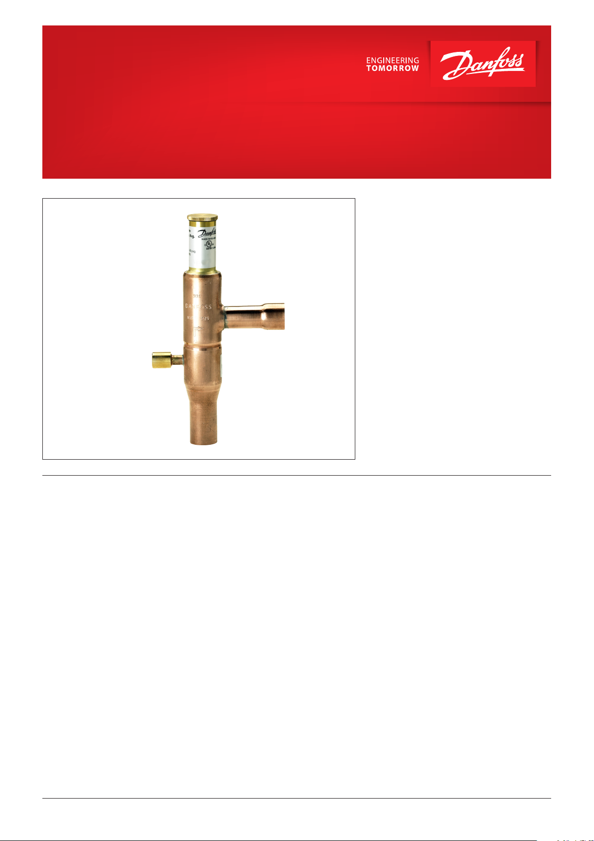
Evaporator pressure regulator
Type KVP
The KVP is mounted in the suction line after the
evaporator and is used to:
1. Maintain a constant evaporating pressure and
thereby a constant surface temperature on the
evaporator. The regulation is modulating.
By throttling in the suction line, the amount of
refrigerant gas is matched to the evaporator
load.
2. Protect against an evaporating pressure that is
too low (e.g. as protection against freezing in
a water chiller). The regulator closes when the
pressure in the evaporator falls below the set
value.
3. Differentiate between the evaporating
pressures in two or more evaporators in
systems with one compressor.
Features • Accurate, adjustable pressure regulation
• Wide capacity and operating range
• Pulsation damping design
• Stainless steel bellows
• Compact angle design for easy installation in
any position
• “Hermetic” brazed construction
• 1⁄4 in. Schrader valve for pressure testing
• Available with flare and ODF solder
connections
• KVP 12 – KVL 22: may be used in the following
EX range: Category 3 (Zone 2)
© Danfoss | DCS (az) | 2018.03
DKRCC.PD.HA0.D8.02 | 1
Page 2
Data sheet | Evaporator pressure regulator, type KVP
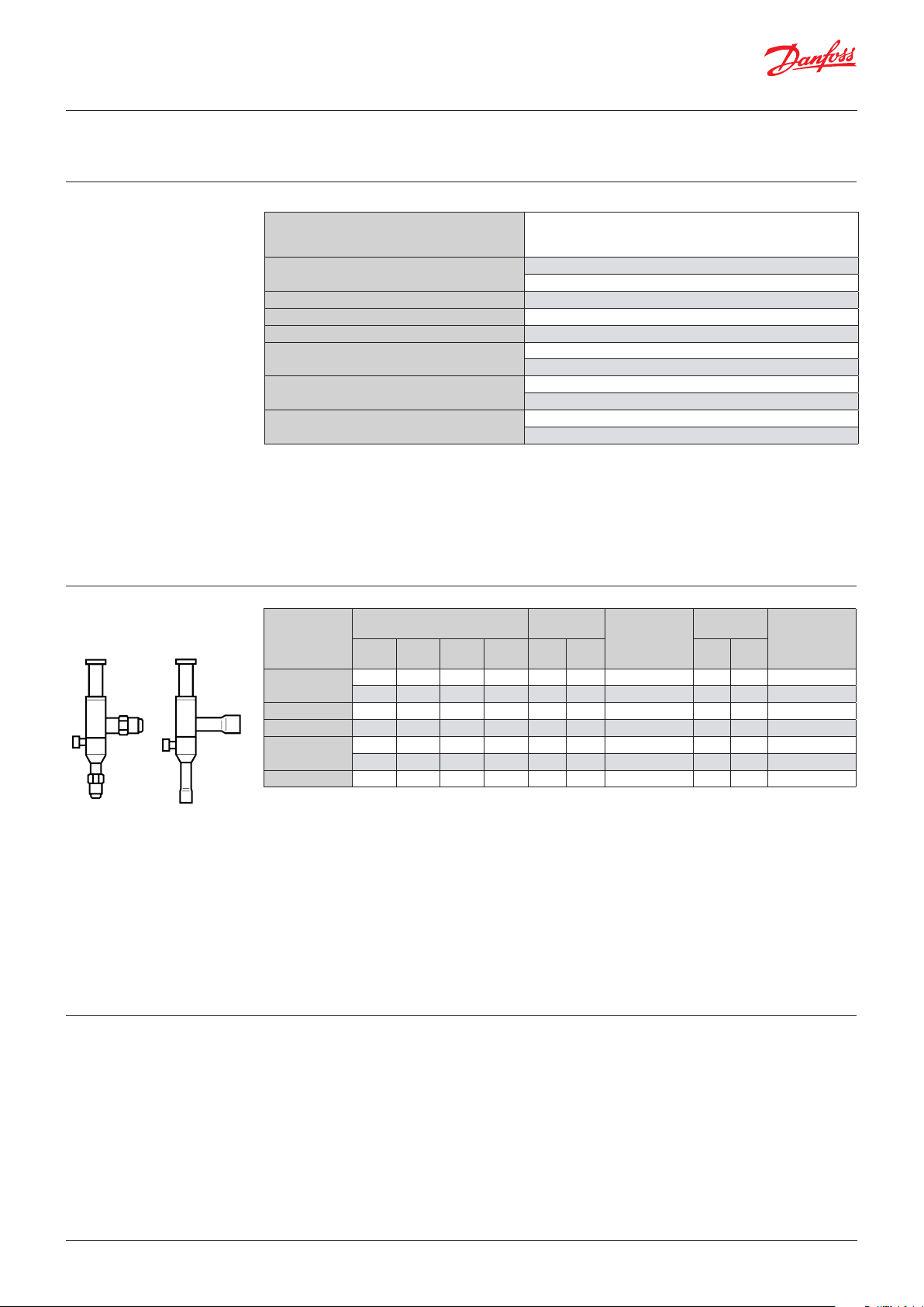
Approvals
Technical data
UL LISTED, file SA7200
R22, R1270*, R134a, R290*, R404A, R407A, R407C, R407F, R448A, R4 49A,
Refrigerants
Regulating range
Maximum working pressure PS/MWP PS = 18 bar
Maximum test pressure Pe = PS × 1.1 = 19.8 bar
Medium temperature range -45 – 130 °C
Maximum P-band
Kv-value 1) with offset 0.6 bar
Kv-value 1) with maximum P-band
1
) The Kv value is the flow of water in [m3 / h] at a pressure drop across valve of 1 bar, ρ = 1000 kg / m3.
This product (KVP 12 – KVP 22) is evaluated for
R290, R600, R600a and R1270 by ignition source
assessment in accordance with standard
EN13463 -1.
R450A, R452A, R507A, R513A, R600*, R600a*
* KVP 12 – KVP 22 only
0 – 5.5 bar
Factory setting = 2 bar
KVP 12 – 22: 1.7 bar
KVP 28 – 35: 2.8 bar
KVP 12 – 22: 1.7 m3 / h
KVP 28 – 35: 2.8 m3 / h
KVP 12 – 22: 2.5 m3 / h
KVP 28 – 35: 8.0 m3 / h
For complete list of approved refrigerants,
visit www.products.danfoss.com and search for
individual code numbers, where refrigerants are
listed as part of technical data.
Ordering
REACH requirements
Rated capacity 1)
Type
KVP 12
KVP 15 4.0 2.8 3.6 3.7
KVP 22 4.0 2.8 3.6 3.7 – – –
KVP 28
KVP 35 8.6 6.1 7.7 7.9 – – – 1 3⁄8 35 034L0032
1
) Rated capacity is the regulator capacity at
evaporating temperature te = -10 °C
condensing temperature tc = 25 °C
pressure drop in regulator Δp = 0.2 bar
offset = 0.6 bar
To select the product for other conditions or refrigerants, use Danfoss Coolselector®2.
2
) KVP supplied without flare nuts. Separate flare nuts can be supplied:
1⁄2 in / 12 mm, code no. 011L1103
5⁄8 in / 16 mm, code no. 011L1167
R22 R134a
4.0 2.8 3.6 3.7
4.0 2.8 3.6 3.7 – – – – 12 034L0028
8.6 6.1 7.7 7.9 – – – 1 1⁄8 – 034L0026
8.6 6.1 7.7 7.9 – – – – 28 034L0031
[kW]
R404A/
R407C [in] [mm] [in] [mm]
R507
Flare
connection 2)
1
⁄2 12 034L0021
5
⁄8 16 034L0022
Code no.
Solder
connection
1
⁄2 – 034L0023
5
⁄8 16 034L0029
7
⁄8 22 034L0025
Code no.
The connection dimensions chosen must not be
too small, as gas velocities in excess of 40 m / s at
the inlet of the regulator can result in flow noise.
Note:
All Danfoss products fulfill the requirements in
REACH.
One of the obligations in REACH is to inform
customers about presence of Candidate list
substances if any, we hereby inform you about
one substance on the candidate list: an O-ring
used in this product contains Diisopentylphthalat
(CAS no: 605-50-5) in a concentration above
0.1% w/w.
© Danfoss | DCS (az) | 2018.03
DKRCC.PD.HA0.D8.02 | 2
Page 3
Data sheet | Evaporator pressure regulator, type KVP
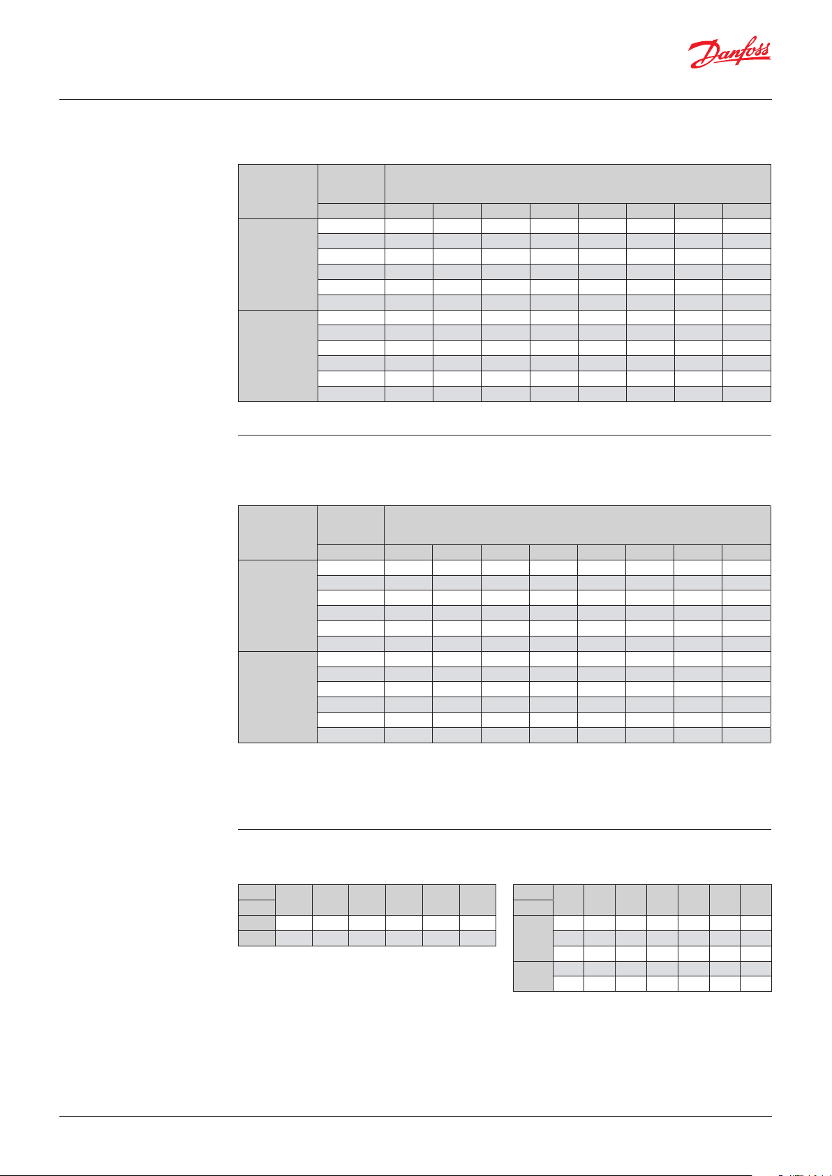
Capacity
Regulator capacity Qe 1) [kW] with offset = 0.6 bar
Pressure drop
Type
KVP 12
KVP 15
KVP 22
KVP 28
KVP 35
in regulator
∆p
[bar] -30 -25 -20 -15 -10 -5 0 5
0.1 1.9 2.1 2.3 2.6 2.9 3.2 3.5 3.8
0.2 2.5 2.9 3.2 3.6 4.0 4.4 4.9 5.3
0.3 3.0 3.4 3.8 4.3 4.8 5.3 5.9 6.5
0.4 3.3 3.8 4.3 4.9 5.5 6.1 6.7 7.4
0.5 3.4 4.1 4.7 5.3 6.0 6.7 7.4 8.2
0.6 3.6 4.2 5.0 5.7 6.4 7.2 8.0 8.8
0.1 4.0 4.5 5.0 5.6 6.2 6.8 7.5 8.2
0.2 5.4 6.2 6.9 7.7 8.6 9.5 10.4 11.4
0.3 6.3 7.3 8.2 9.3 10.3 11.5 12.6 13.9
0.4 7.0 8.1 9.2 10.4 11.7 13.0 14.4 15.8
0.5 7.4 8.7 10.0 11.4 12.8 14.3 15.9 17.5
0.6 7.6 9.1 10.6 12.2 13.8 15.4 17.1 18.9
Regulator capacity Qe 1) [kW] with offset = 0.6 bar
Pressure drop
Type
KVP 12
KVP 15
KVP 22
KVP 28
KVP 35
1
) The capacities are based on
liquid temperature ahead of expansion valve tl = 25 °C
regulator offset = 0.6 bar
Dry saturated gas ahead of regulator
in regulator
∆p
[bar] -15 -10 -5 0 5 10 15 20
0.1 1.8 2.1 2.3 2.6 2.9 3.2 3.6 3.9
0.2 2.5 2.8 3.2 3.6 4.0 4.5 5.0 5.5
0.3 2.9 3.4 3.8 4.3 4.9 5.4 6.0 6.6
0.4 3.2 3.7 4.3 4.9 5.5 6.1 6.8 7.6
0.5 3.4 4.0 4.6 5.3 6.0 6.8 7.5 8.3
0.6 3.5 4.2 4.9 5.7 6.4 7.3 8.1 9.0
0.1 3.9 4.5 5.0 5.6 6.2 6.9 7.6 8.4
0.2 5.3 6.1 6.9 7.8 8.7 9.6 10.6 11.7
0.3 6.3 7.2 8.2 9.3 10.4 11.6 12.9 14.2
0.4 6.9 8.0 9.2 10.5 11.8 13.2 14.6 16.2
0.5 7.3 8.6 10.0 11.4 12.9 14.5 16.1 17.9
0.6 7.5 9.0 10.5 12.1 13.8 15.6 17.4 19.3
Evaporating temperature t
[°C]
Evaporating temperature te [°C]
R22
e
R134 a
© Danfoss | DCS (az) | 2018.03
Correction factors for liquid temperature t
t
l
[°C]
R22 0.93 0.96 1.0 1.04 1.08 1.13
R134a 0.92 0.96 1.0 1.05 1.10 1.16
15 20 25 30 35 40
l
Correction factors for offset
Offset
[bar]
KVP 12
KVP 15
KVP 22
KVP 28
KVP 35
0.2 0.4 0.6 0.8 1.0 1.2 1.4
2.5 1.4 1.0 0.77 0.67 0.59 –
2.5 1.4 1.0 0.77 0.67 0.59 –
2.5 1.4 1.0 0.77 0.67 0.59 –
– 1.4 1.0 0.77 0.67 0.59 0.53
– 1.4 1.0 0.77 0.67 0.59 0.53
DKRCC.PD.HA0.D8.02 | 3
Page 4

Data sheet | Evaporator pressure regulator, type KVP
Capacity
(continued)
Regulator capacity Qe 1) [kW] with offset = 0.6 bar
Pressure drop
Type
KVP 12
KVP 15
KVP 22
KVP 28
KVP 35
in regulator
∆p
[bar] -35 -30 -25 -20 -15 -10 -5 0
0.1 1.4 1.6 1.8 2.1 2.3 2.6 2.8 3.2
0.2 1.9 2.2 2.5 2.8 3.2 3.6 4.0 4.4
0.3 2.2 2.5 3.0 3.5 3.9 4.4 4.8 5.4
0.4 2.4 2.9 3.3 3.9 4.3 4.9 5.5 6.2
0.5 2.5 3.1 3.6 4.2 4.8 5.5 6.1 6.8
0.6 2.6 3.2 3.9 4.4 5.1 5.8 6.5 7.4
0.1 2.9 3.4 3.9 4.4 5.0 5.5 6.0 6.8
0.2 4.0 4.7 5.4 6.2 6.8 7.7 8.4 9.6
0.3 4.7 5.5 6.4 7.3 8.2 9.2 10.3 11.6
0.4 5.1 6.1 7.2 8.2 9.3 10.5 11.7 13.2
0.5 5.5 6.6 7.7 9.0 10.2 11.4 12.9 14.5
0.6 5.7 6.9 8.2 9.6 10.9 12.4 13.8 15.7
Regulator capacity Qe 1) [kW] with offset = 0.6 bar
Pressure drop
Type
KVP 12
KVP 15
KVP 22
KVP 28
KVP 35
1
) The capacities are based on
liquid temperature ahead of expansion valve tl = 25 °C
regulator offset = 0.6 bar
Dry saturated gas ahead of regulator
in regulator
∆p
[bar] -30 -25 -20 -15 -10 -5 0 5
0.1 1.6 1.8 2.0 2.3 2.7 3.0 3.3 3.6
0.2 2.2 2.5 2.8 3.2 3.7 4.1 4.6 5.1
0.3 2.6 3.0 3.4 3.9 4.4 4.9 5.5 6.2
0.4 2.8 3.3 3.8 4.4 5.1 5.7 6.3 7.1
0.5 2.9 3.6 4.2 4.8 5.5 6.2 7.0 7.9
0.6 3.1 3.7 4.5 5.1 5.9 6.7 7.5 8.4
0.1 3.4 3.9 4.5 5.0 5.7 6.3 7.1 7.9
0.2 4.6 5.4 6.1 6.9 7.9 8.8 9.8 10.9
0.3 5.4 6.4 7.3 8.4 9.5 10.7 11.8 13.3
0.4 6.0 7.0 8.2 9.4 10.8 12.1 13.5 15.2
0.5 6.4 7.6 8.9 10.3 11.8 13.3 14.9 16.8
0.6 6.5 7.9 9.4 11.0 12.7 14.3 16.1 18.1
R404A/R507
Evaporating temperature te [°C]
R407C
Evaporating temperature te [°C]
© Danfoss | DCS (az) | 2018.03
Correction factors for temperature t
t
l
[°C]
R404A/R507 0.89 0.94 1.0 1.07 1.16 1.26
R407C 0.91 0.95 1.0 1.05 1.11 1.18
15 20 25 30 35 40
l
Correction factors for offset
Offset
[bar]
KVP 12
KVP 15
KVP 22
KVP 28
KVP 35
0.2 0.4 0.6 0.8 1.0 1.2 1.4
2.5 1.4 1.0 0.77 0.67 0.59 –
2.5 1.4 1.0 0.77 0.67 0.59 –
2.5 1.4 1.0 0.77 0.67 0.59 –
– 1.4 1.0 0.77 0.67 0.59 0.53
– 1.4 1.0 0.77 0.67 0.59 0.53
DKRCC.PD.HA0.D8.02 | 4
Page 5

Data sheet | Evaporator pressure regulator, type KVP
Sizing
Valve selection
For optimum performance, it is important to
select a KVP valve according to system conditions
and applications.
Example
When selecting the appropriate valve it may
be necessary to convert the actual evaporator
capacity using a correction factor.
This is required when your system conditions are
different than the table conditions.
The selection is also dependant on the
acceptable pressure drop across the valve.
The following data must be used when sizing
a KVP valve:
• Refrigerant
• Evaporator capacity: Qe in [kW]
• Evaporating temperature
(required temperature): te in [°C]
• Minimum evaporating temperature: te in [°C]
• Liquid temperature ahead of expansion valve:
tl in [°C]
• Connection type: flare or solder
• Connection size in [in.]
The following example illustrates how this is
done:
• Refrigerant: R134a
• Evaporator capacity: Qe = 4.2 kW
• Evaporating temperature: te = 5 °C ~ 2.5 bar
• Minimum evaporating temperature:
1.4 °C ~ 2.1 bar
• Liquid temperature ahead of expansion valve:
tl = 30 °C
• Connection type: Solder
• Connection size: 5⁄8 in.
Step 1
Determine the correction factor for liquid
temperature tl ahead of expansion valve.
Correction factors for liquid temperature t
t
l
[°C]
R134a 0.88 0.92 0.96 1.0 1.05 1.10 1.16 1.23 1.31
R22 0.90 0.93 0.96 1.0 1.05 1.10 1.13 1.18 1.24
R404A/R507 0.84 0.89 0.94 1.0 1.07 1.16 1.26 1.40 1.57
R407C 0.88 0.91 0.95 1.0 1.05 1.11 1.18 1.26 1.35
10 15 20 25 30 35 40 45 50
l
Step 2
Determine the correction factor for the valve
offset.
The offset is defined as the difference between
the design evaporating pressure and the
minimum evaporating pressure.
From the offset correction factor table, an offset
of 0.4 bar (2.5 – 2.1) corresponds to a factor of 1.4.
From the correction factors table (see below) a
liquid temperature of 30 °C, R134a corresponds
to a factor of 1.05.
Correction factors for offset
Offset
[bar]
KVP 12
KVP 15
KVP 22
KVP 28
KVP 35
0.2 0.4 0.6 0.8 1.0 1.2 1.4
2.5 1.4 1.0 0.77 0.67 0.59 –
2.5 1.4 1.0 0.77 0.67 0.59 –
2.5 1.4 1.0 0.77 0.67 0.59 –
– 1.4 1.0 0.77 0.67 0.59 0.53
– 1.4 1.0 0.77 0.67 0.59 0.53
© Danfoss | DCS (az) | 2018.03
Step 3
Corrected evaporator capacity is
Qe = 1.05 × 1.4 × 4.2 = 6.2 kW
DKRCC.PD.HA0.D8.02 | 5
Page 6

Data sheet | Evaporator pressure regulator, type KVP
Valve selection
(continued)
Design / Function KVP
1. Protective cap
2. Gasket
3. Setting screw
4. Main spring
5. Valve body
6. Equalization bellows
7. Valve plate
8. Valve seat
9. Damping device
10. Pressure gauge
connection
11. Cap
12. Gasket
13. Insert
Step 4
Now select the appropriate capacity table
(R134a) and choose the column for an
evaporating temperature of te = 5 °C.
Using the corrected evaporator capacity, select
a valve that provides an equivalent or greater
capacity at an acceptable pressure drop.
KVP 12, KVP 15, KVP 22 delivers 6.4 kW
at a 0.6 bar pressure drop across the valve.
Step 5
KVP 15, 5⁄8 in. solder connection:
code no. 034L0029, see Ordering table.
KVP 28, KVP 35 delivers 6.2 kW at a 0.1 bar
pressure drop across the valve.
Based on the required connection size of 5⁄8 in.,
the KVP 15 is the proper selection for this
example.
1
2
3
4
5
6
7
8
9
10
11
12
13
© Danfoss | DCS (az) | 2018.03
The evaporator pressure regulator, type KVP
opens on a rise in pressure on the inlet side, i.e.
when the pressure in the evaporator exceeds the
set value.
Type KVP regulates inlet pressure only.
Pressure variations on the outlet side of the
regulator do not affect the degree of opening as
the valve is equipped with equalization bellows (6).
The bellows have an effective area corresponding
to that of the valve seat neutralising any affect to
the setting.
The KVP is also equipped with a damping device
(9) providing protection against pulsations which
can normally arise in a refrigeration system.
The damping device helps to ensure long life
for the regulator without impairing regulation
accuracy.
DKRCC.PD.HA0.D8.02 | 6
Page 7

Data sheet | Evaporator pressure regulator, type KVP
P-band and Offset
Capacity
Setting
offset
P- band
Danfoss
34L181.10
[bar]
Proportional band
The proportional band or P-band is defined as
the amount of pressure required to move the
valve plate from a closed to a fully open position.
Example
If the valve is set to open at 4 bar and the valve
P-band is 1.7, the valve will provide maximum
capacity when the inlet pressure reaches 5.7 bar.
Offset
The offset is defined as the permissible pressure
variation in evaporator pressure (temperature).
It is calculated as the difference between the
required working pressure and the minimum
allowable pressure.
The offset is always a part of the P-band.
Example with R22
A working temperature of 5 °C ~ 4.9 bar is
required, and the temperature must not drop
below 0.5 °C ~ 4.1 bar.
The offset will then be 0.8 bar.
When selecting a valve, be sure to correct the
evaporator capacity based on the required offset.
© Danfoss | DCS (az) | 2018.03
DKRCC.PD.HA0.D8.02 | 7
Page 8

Danf
already on order pro
All trademarks in this material are property of the respec
Dimensions and weights
Type
KVP 12
KVP 15
Connection
Flare Solder ODF
[in.] [mm] [in.] [mm]
1
⁄2 121⁄2 12 19 19 179 99 66 64 41 10 30 0.4
5
⁄8 165⁄8 16 24 24 179 99 66 64 41 12 30 0.4
NV1NV2H1H2H3B1B2C øD
[mm] [mm] [mm] [mm] [mm] [mm] [mm] [mm] [mm] [Kg]
Net
weight
KVP 22 – –7⁄8 22 24 24 179 99 66 64 41 17 30 0.4
KVP 28 – – 1 1⁄8 28 24 24 259 151 103 105 48 20 43 1.0
3
KVP 35 – – 1
⁄8 35 – – 259 151 103 105 48 25 43 1.0
oss can accept no responsibility for possible errors in catalogues, brochures and other printed material. Danfoss reserves the right to alter its products without notice. This also applies to products
vided that such alterations can be made without subsequential changes being necessary eady agreed.
© Danfoss | DCS (az) | 2018.03
tive companies. Danfoss and the Danfoss logotype are trademarks of Danfoss A/S. All rights reserved.
DKRCC.PD.HA0.D8.02 | 8
 Loading...