

Page 1
remote bulb air coil/room sensor
Danfoss
060L2107
Danfoss
060L2107
Installation Guide
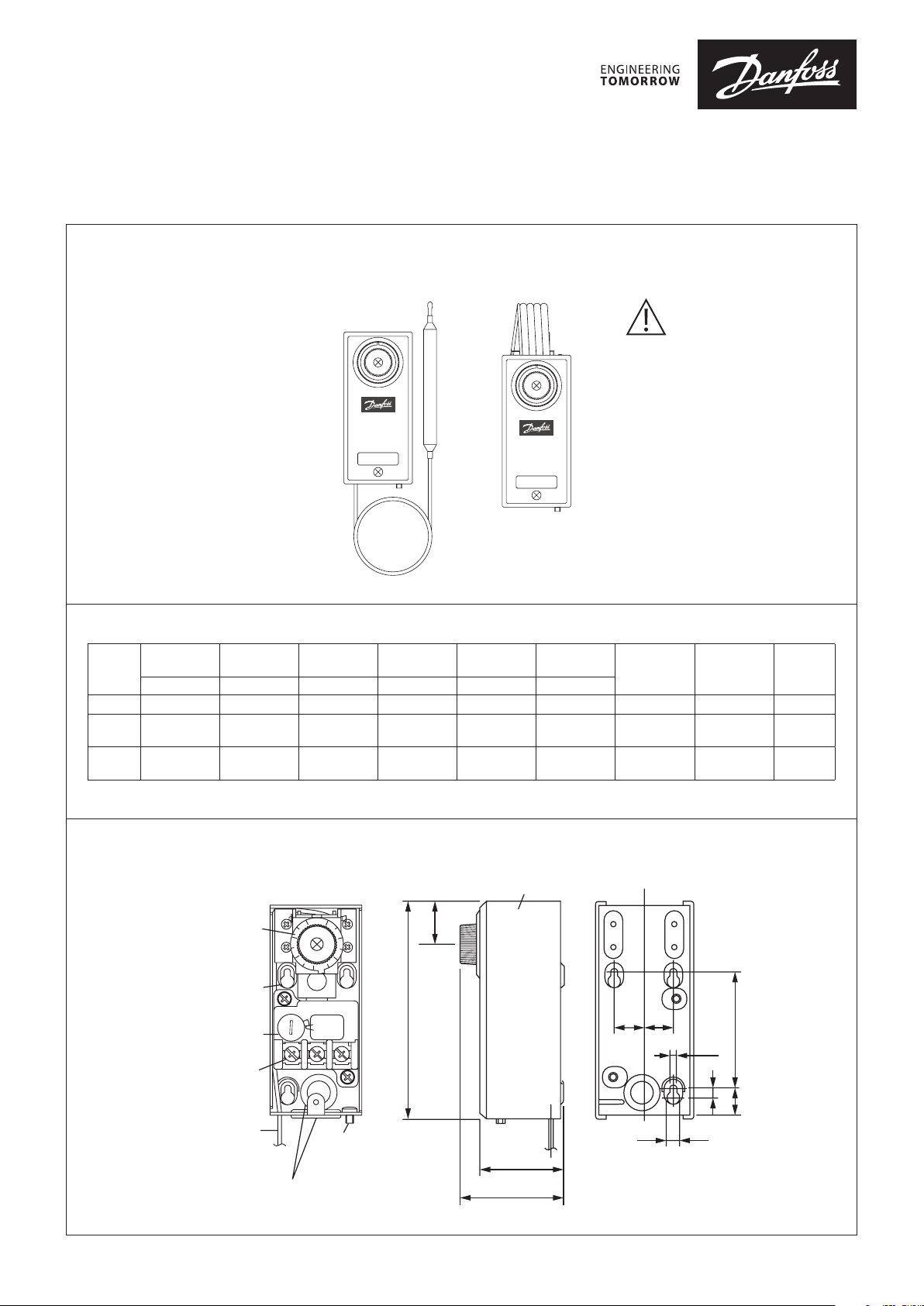
Thermostat
Type KPU 19
Application
KPU 19 thermostats are used for
060R9771
temperature regulation in refrigeration,
freezing, air conditioning, ventilating
and heating systems.
KPU 19 thermostats are fitted with
Single-Pole Double-Throw (SPDT)
or Single-Pole Single-Throw (SPST)
contact system.
The standard KPU 19 enclosure is rated
NEMA ~ 1.
NEMA ~ 1 is obtained when the
thermostat is mounted on a flat surface
with all unused holes covered.
Product specification
Regulating
Type
range
[°F] ∆T [°F] [in.] [in.] [°F] [°F]
KPU 19 -30 – 80 3.6 – 12.6
KPU 19 -30 – 80 3.6 – 12.6
KPU 19 -30 – 80 3.6 – 12.6 -
Differential Bulb size
Thermostat bulb types
Remote bulb Air coil/room sensor
3
/8 x 4 1/
3
/8 x 4 1/
tube length
2
2
Room sensor
Capillary
120 140
80 140
Air coil /
Max. bulb
temperature
140
Ambient
temperature
-31 – 140
-31 – 140
-31 – 140
Important
The KPU 19 thermostat is designed
only for use as a temperature
regulating operating control. It is
the responsibility of the installer
to verify that other necessary
safety controls are installed and
functioning properly as intended
by the original equipment
manufacturer or system design.
Contact
type
SPDT Auto. 060L2150
SPST (close
on temp. rise)
SPDT Auto. 060L2152
Reset
type
Code no.
Auto. 060L2151
060R9771
Dimensions [in.]
Scale Plate
Mounting Hole
Di. Adjusting
Terminal Screw
Capillary Tube
© Danfoss | DCS (az) | 2018.10
Knob
Conduit Rubber
6
5
4
M
3
2
I
N
DIFF.
Grounding Screw
4.48
0.88
2.12
Cover
1.7
0.63 0.59
0.27
Danfoss
060L2101
2.4
0.14
0.19
0.55
DKRCC.PI.CA0.F2.22 | 1
Page 2
Danf
060L2110
Installation
Select an accessible location, where
the thermostat will not be subject
to damage. Mount the KPU 19 on a
bracket or on a completely flat surface.
Mounting on an uneven surface may
cause incorrect thermostat operation.
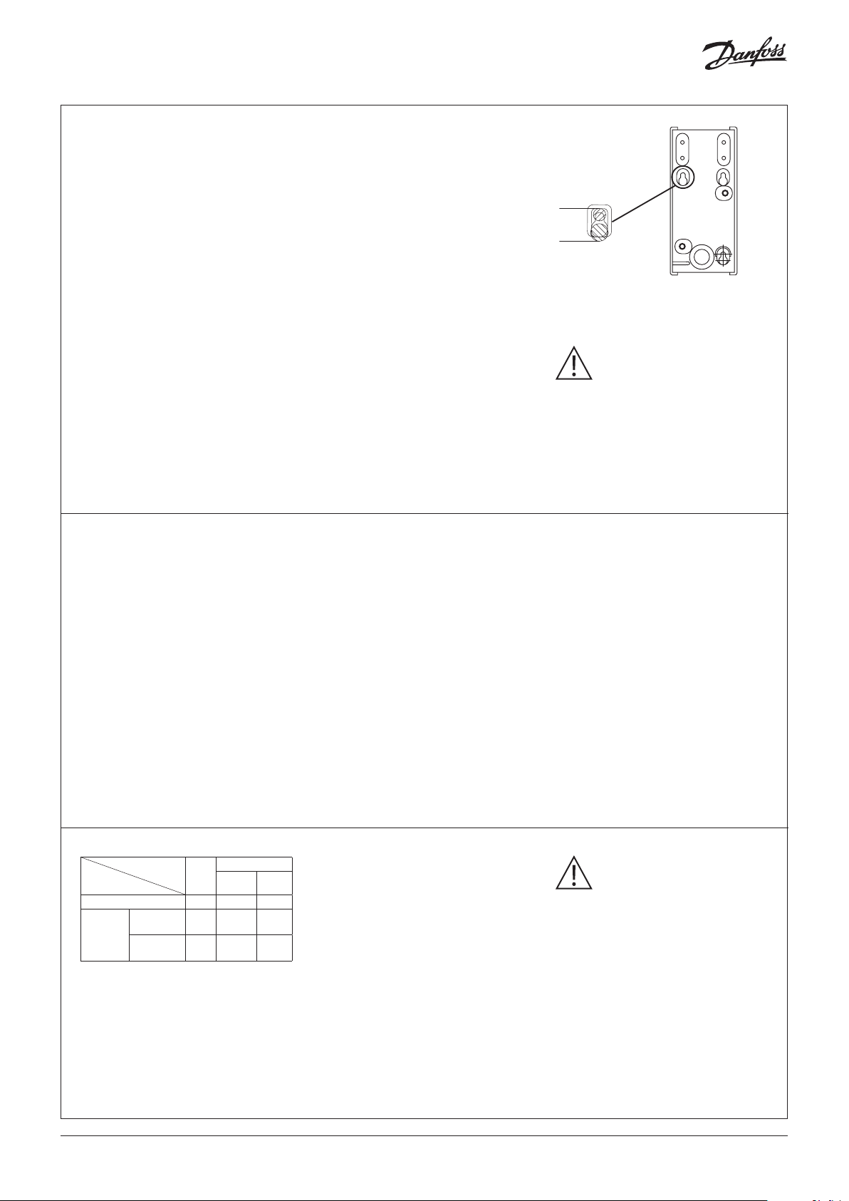
Use only the mounting holes provided
at the back of the metal housing.
Do not make additional holes.
Locking mounting holes must be
fastened at position A as shown in
diagram to the right.
Fastening at position “B” may result
in housing deformation and KPU 19
malfunction.
A
B
oss
The KPU 19 thermostat and the
sensing bulb can be mounted in any
position.
The sensing element is filled in with
liquid expansion type charging with
no limitations in terms of temperature
at switch body (TS), temperature at
sensing bulb (TB) or temperature at
capillary tube (TC). KPU 19 can operate
in all following conditions:
TS > TB; TS < TB, TS = TB.
Taking into consideration time
constant of the thermostat it is
recommended to install KPU 19 where
temperature is not changing rapidly.
General recommendations for
capillary tube and bulb installation:
1. Protect the capillary tube from
damage due to vibration.
a) When the thermostat unit is
mounted directly on the compressor,
the capillary tube must be secured to
the compressor so that both vibrate
together.
b) For mounting otherwise, form
surplus capillary tube into a loose
loop and secure the loop to the base
on which the thermostat is mounted.
2. Leave a little slack in the capillary
tube to help dampen vibration.
Fast changes of the measured
temperature will cause thermostat
measurements lags behind actual
temperature changes in the
application. Make sure to keep
temperature variable acceleration
within 3 minutes per 1.8 °F at liquid, or
within 18 minutes per 1.8 °F at air. KPU
should be installed in a place in which
harmful environmental conditions like
radiation from sun, lamps or radiator is
minimalized.
Cooling due to the extensive air flow
might affect thermostat performance
as well.
3. Avoid sharp bends (with the radius
of 1/2" or less) and bending the capillary
tube at the same point several times,
as these actions can weaken the
material and increase the likelihood of
the tube cracking.
4. Bending of the capillary tube within
1.75" from soldering point with bulb is
not allowed.
5. Form and locate the capillary tube
away from sharp or abrasive objects
that might damage it.
It is recommended to install the
thermostat at a place where vibration
is 1G or less.
Important
Do not dent or deform the bulb of the
thermostat, as doing so could damage
the bulb and cause charge
leakage.
Do not turn any other screws except
screws on the scale plate, on the micro
switch knob and on the terminal block.
6. For thermostats with room sensor
coils, make sure that placement allows
free airflow around the coil and bulb.
At the same time, ensure that the bulb
is not exposed to drafts from doors, or
to heat radiated from the evaporator
surface. Make sure that the bulb does
not come into contact with a wall
surface. Never mount the thermostat
directly on a cold wall. Instead, mount
the unit on an insulating plate.
7. KPU 19 sensing bulb is made of
copper, copper alloy, silver solder – do
not use it for media which are harmful
for these materials.
Wiring Note Caution
Voltage [V]
Amps [A]
Resistive load 1 0.5 ~ 16 0.5 ~ 8
Full load
Inductive
load
Amps
Locked
rotor Amps
P.F.
cos Ø
0.75 0.5 ~ 16 0.5 ~ 8
0.45 96 48
Pilot duty: 125 VA; 120/240 V AC
A C
120 240
All wiring should conform to the
National Electrical Code and to
applicable local regulations.
Use only copper wire.
Use only the terminal screws furnished
in the terminal block.
Do not exceed tightening torque of
10 lb. in. (1.18 Nm).
Do not exceed the thermostat’s
specified electrical ratings.
Do not use impact driver(shock driver).
The terminal block as well as
grounding screw are accessible after
removing the front cover.
© Danfoss | DCS (az) | 2018.10
Do not remove cover while power
is supplied as it may cause electrical
shock.
To avoid the possibility of electric
shock and damage to equipment,
disconnect the power supply before
any wiring connections are made.
Never touch current conducting (LIVE)
parts with your fingers or with tools.
Electrical wires should be connected
through the conduit rubber or
alternatively by conduit boss.
DKRCC.PI.CA0.F2.22 | 2
Page 3

cut-out on temperature decrease
4
3
2
5
6
M
I
N
LOAD
cut-out on temperature increase
~LINE
Danfoss
060L2108
cut-out on temperature increase
56
Wiring options For Cooling Unit For Heating Unit
Danfoss
060L2108
Contact function
h
HL C
SPDT
Cooling
Unit
Power Source
For Cooling Unit
Contact function
HCL
6
5
4
I
N
M
3
2
LOAD
~LINE
Example for application and wiring
h
Heating
Unit
Power Source
HL
h
C
Manual
Changeover
Switch
Cooling
Unit
Power Source
For Heating Unit
Arrow marking indicates a direction of switch action.
Example for application and wiring
6
5
4
I
N
M
3
2
LOAD
h
C
HL
Heating
Unit
For both cooling and
Heating with Manual
Changeover Switch
~LINE
Danfoss
060L2103
Adjustment Determination of differential
Note
Adjust the thermostat to settings
specified by the manufacturer of the
controlled equipment. When checking
thermostat operation, or operating the
controlled equipment, do not exceed
the manufacturer’s temperature
ratings for the controlled equipment
or for any of its components. To avoid
inaccurate thermostat operation, do
not adjust the KPU’s pointers beyond
the highest or lowest indicator marks
on the scale plate.
Scale is indicative only. For accurate
setting please use thermometer.
h
HC
SPST For Cooling Unit
Arrow marking indicates a direction of switch action.
Cooling
Unit
Power Source
h
C
H
14.4
12.6
10.8
9.0
7.2
(°F)
5.4
3.6
TEMP. DIFFERENTIAL
1.8
MIN.
Danfoss
060L2104
TEMP. DIFFERENTIAL
2
34
DIFF. ADJUSTING KNOB
Danfoss
060L2109
© Danfoss | DCS (az) | 2018.10
DKRCC.PI.CA0.F2.22 | 3
Page 4

060L2106
Setting example (SPDT type)
Set at 41 °F for temp. decrease and
50 °F for temp. increase.
Upper Switch Point (USP): 50 °F
Lower Switch Point (LSP): 41 °F
Contact
Action
C-L OFF
C-H ON
decreasing
Danfoss
060L2105
Fig. 2 Fig. 1
Scale Plate
Indictator
Danfoss
1. Set at 41 °F
Turn the scale plate to match indicator
pointer with the required value (verify
with the thermometer)
2. Set at 50 °F
Calculate the differential between USP
and LSP (Differential = USP – LSP;
50 °F - 41 °F = 9 °F ).
Find the proper Differential
Adjusting Knob position from the
characteristic presented on the graph
"Determination of differential ".
C-L ON
C-H OFF
increasing
41 ºF 50 ºF
Dierential
Set point
Temp. rising
The same characteristics is shown on
the back side of the KPU 19 cover.
Differential of 9 °F is equivalent to the
indication 4 set on the Differential
Adjustment Knob.
3. After setting, install the cover and
supply power supply for checking
the actual switching points. Adjust
the setting if necessary as scales are
indicative only.
6
Di. Adjusting
Knob
Di. Indicator
5
4
I
N
M
DIFF.
3
2
Enclosed accessories:
• Sensor clamp for bulb fastening.
• Blinding sticker to cover the hole
after dial knob removal. Blinding
sticker can be used only once.
• Hand knob for adjustment.
Note
Scale values are indicative only. It is
often necessary to use a thermometer
when setting working points.
© Danfoss | DCS (az) | 2018.10
DKRCC.PI.CA0.F2.22 | 4
 Loading...