

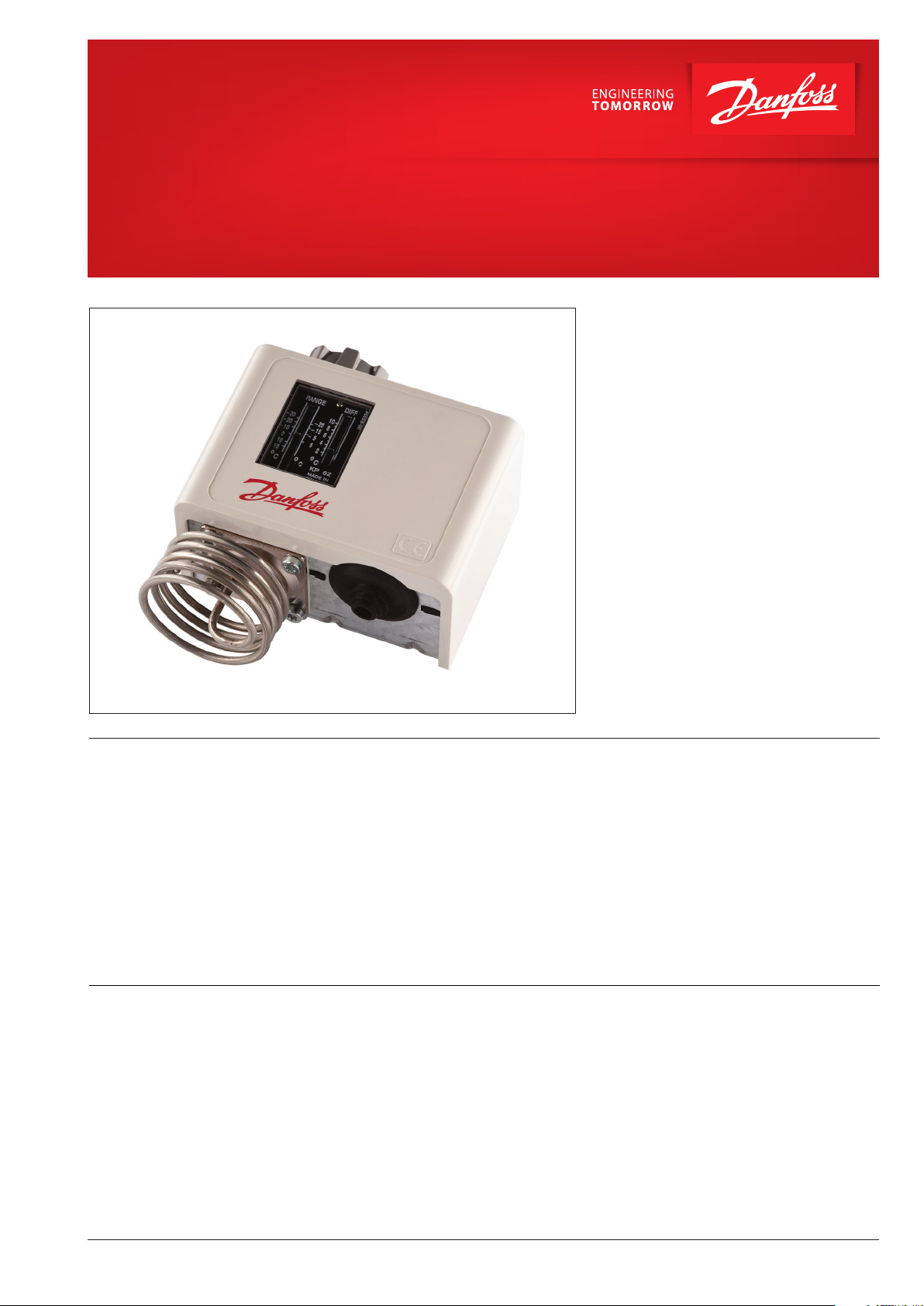
Shut-off and regulating valves
Thermostat
for Industrial Refrigeration
KP
The KP Thermostats are single-pole, doublethrow (SPDT) temperature-operated electric
switches.
They can be connected directly to a single-phase
AC motor of up to approx.
2 kW or installed in the control circuit of
DC motors and large AC motors.
The KP Thermostats are used for regulation, but
can also be seen in safety monitoring systems.
They are available with vapour charge or with
adsorption charge.
With vapour charge the differential is very small.
The KP Thermostats with adsorption charge are
widely used to give frost protection.
Features • Wide regulating range
• Can be used for deep freeze, refrigeration
and air conditioning plant
• Welded bellows elements mean increased
reliability
• Small dimensions.
Easy to install in refrigerated counters or
cold rooms
• Ultra-short bounce times.
This gives long operating life, reduces wear to
a minimum and increases reliability
Approvals China Compulsory Certificate, CCC
Ship approvals Germanischer Lloyd, GL (excluding KP 98)
CE-marked in accordance with EN 60947-4/-5 for
sale in Europe
Registro Italiano Navale, RINA
Bureau Veritas, France, BV (excluding KP 98)
Lloyd’s Register, LR (excluding KP 79, KP 81, KP 98)
• Standard versions with changeover switch.
Possible to obtain opposite contact function or
to connect a signal
• Electrical connection at the front of the unit.
Facilitates rack mounting
Saves space
• Suitable for alternating and direct current
• Cable entry of soft thermoplastic for cables
from 6 to 14 mm diameter
• Extensive and wide range
Underwriters Laboratories Inc., US – UL
GOST
Russian Maritime Register of Shipping, RMRS
Note: Marine Approvals do not cover KP 98 dual
thermostat.
© Danfoss | DCS (mwa) | 2018.10
AF237586440562en-000405 | 5
Thermostat, type KP
Technical data
Ambient temperature -40 – 65 °C (80 °C for max. 2 hours).
Switch Single-pole, double-throw (SPDT) changeover switch.
Contact load
Wire dimensions
Tightening torque max. 2 Nm
Rated impulse voltage 4 kV
Pollution degree 3
Short circuit protection, fuse 16 A
Insulation 400 V
Enclosure 30/44
Alternating current
Direct current DC13: 12 W, 220 V control current
solid / stranded 0.75 – 2.5 mm
flexible, without ferrules 0.7 – 2.5 mm
flexible, with ferrules 0.5 – 1.5 mm
Cable connection
Cable entry for cables 6 – 14 mm dia.
A Pg 13.5 screwed cable entry can be used
for 6 – 14 mm dia. cables.
With 8 – 16 mm cables a standard Pg 16 screwed
cable entry can be used.
AC1 =16 A, 400 V
AC3 = 16 A, 400 V
2
2
2
Enclosure
IP30 to EN 60529 / IEC 529
This grade of enclosure is obtained when the
unit is mounted on a flat surface or bracket.
The bracket must be fixed so that all unused
holes are covered.
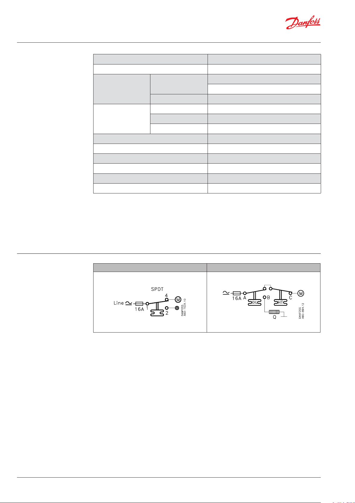
Contact systems
KP temperature control KP 98
6 | AF237586440562en-000405
© Danfoss | DCS (mwa) | 2018.10
Thermostat, type KP
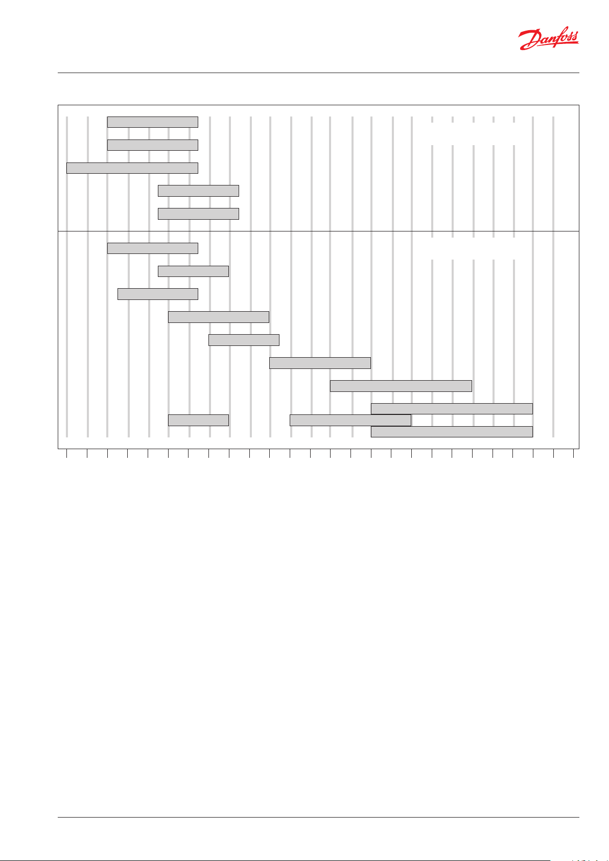
Regulating range
KP 63
KP 61
Vapour range
KP 62
KP 68
KP 69
KP 62
KP 71
KP 73
KP 75
KP 77
KP 79
KP 81
KP 98 OILKP 98 OIL
-50 0 50 100 150 200 °C
Adsorption charge
KP 98 HT
KP 98 HT
© Danfoss | DCS (mwa) | 2018.10
AF237586440562en-000405 | 7

Thermostat, type KP
Ordering
Charge Type Bulb
type
Setting -
range
Differential ∆t Reset Max.
Lowest
temperature
[°C] [°C] [°C] [°C] [m]
KP 61 A
KP 61 A
KP 61 B
KP 61 B
KP 61 B
Vapour 1)
KP 61 A
KP 61 B
KP 62 C 1
KP 63 A
KP 63 B
KP 68 C 1
KP 69 B
KP 62 C 2
KP 71 E 2
KP 71 E 2
KP 73 E 1
KP 73 D 1
KP 73 D 1
KP 73 D 2
KP 73 D 1
Adsorbtion 2)
KP 75 F
KP 75 E 2
KP 77 E 3
KP 77 E 3
KP 77 E 2
KP 79 E 3
KP 81 E 3
KP 81 E 3
KP 98
1)
Bulb must always be placed colder than the thermostat
-30 – 15 5.5 – 23 1.5 – 7
-30 – 15 5.5 – 23 1.5 – 7
-30 – 13 4.5 – 23 1.2 – 7
-30 – 15 5.5 – 23 1.5 – 7
-30 – 15 5.5 – 23 1.5 – 7
-30 – 15
-30 – 15
Fixed 6 Fixed 2 min. 120 5 060L110466
Fixed 6 Fixed 2 min. 120 2 060L110566
-30 – 15 6.0 – 23 1.5 – 7
-50 – 10 10.0 – 70 2.7 – 8
-50 – 10 10.0 – 70 2.7 – 8
-5 – 35 4.5 – 25 1.8 – 7
-5 – 35 4.5 – 25 1.8 – 7
-30 – 15 5.0 – 20 2.0 – 8
-5 – 20 3.0 – 10 2.2 –9
-5 – 20
Fixed 3 Fixed 3 min. 80 2 060L111566
-25 – 15 12.0 – 70 8.0 – 25
-25 – 15 4.0 – 10 3.5 – 9
-25 – 15
Fixed 3.5 Fixed 3.5 min. 80 2 060L113866
-20 – 15 4.0 – 15 2.0 – 13
-25 – 15 3.5 – 20 3.25 – 18
0 – 35 3.5 – 16 2.5 – 12
0 – 35 3.5 – 16 2.5 – 12
20 – 60 3.5 – 10 3.5 – 10
20 – 60 3.5 – 10 3.5 – 10
20 – 60 3.5 – 10 3.5 – 10
50 – 100 5.0 – 15 5.0 – 15
80 – 150 7.0 – 20 7.0 – 20
Fixed 8 Fixed 8 max. 200 2 060L115566
OIL: Fixed 14 OIL: Fixed 14 max. 150 1
HT: Fixed 25 HT: Fixed 25 max. 250 2
E 2
E 2
80 – 150
OIL: 60 – 120
HT: 100 – 180
housing and capillary tube. The thermostat will then regulate
independent of ambient temperature.
2
) Bulb can be placed warmer or colder than thermostat
housing and capillary tube, but variations from 20 °C
ambient temperature will influence the scale accuracy.
Capillary-
bulb
Highest
temperature
temp.
tube
length
aut. 120 2 060L110066
aut. 120 5 060L110166
aut. 120 2 060L110266
aut. 120 2 060L110366 3)
aut. 120 2 060L112866 3) 4)
aut. 120 – 060L110666
aut. 120 2 060L110766
aut. 120 2 060L110866
aut. 120 – 060L111166
aut. 120 2 060L111266
aut. 80 – 060L111066 3) 4)
aut. 80 2 060L111366
aut. 80 2 060L111766
aut. 80 2 060L111866 3)
aut. 55 3 060L114066
aut. 80 2 060L114366
aut. 110 2 060L112066
aut. 110 2 060L113766
aut. 130 2 060L112166
aut. 130 3 060L112266
aut. 130 5 060L116866
aut. 150 2 060L112666
aut. 200 2 060L112566
3
) With manual switch, not isolating switch.
4
) Panel mounting model with top plate.
Code no.
060L113166
8 | AF237586440562en-000405
© Danfoss | DCS (mwa) | 2018.10

Thermostat, type KP
Ordering
(continued)
Thermostat bulb types
A Straight capillary tube
B ø9.5 × 70 mm remote air coil
C
D
E
C1: ø40 × 30 mm air coil
C2: ø25 × 67 mm air coil
(integral with thermostat)
D1: ø10 × 85 mm double contact remote bulb
D2: ø16 × 170 mm double contact remote bulb
Note! Cannot be used in sensor (bulb) pocket
E1: ø6.4 × 95 mm remote bulb
E2: ø9.5 × 115 mm remote bulb
E3: ø9.5 × 85 mm remote bulb
F ø25 × 125 mm remote duct coil
© Danfoss | DCS (mwa) | 2018.10
AF237586440562en-000405 | 9
Thermostat, type KP
60-904.12
17
Danfoss
60-1033.10
Danf
60-272.12
17
Danfoss
60-1032.10
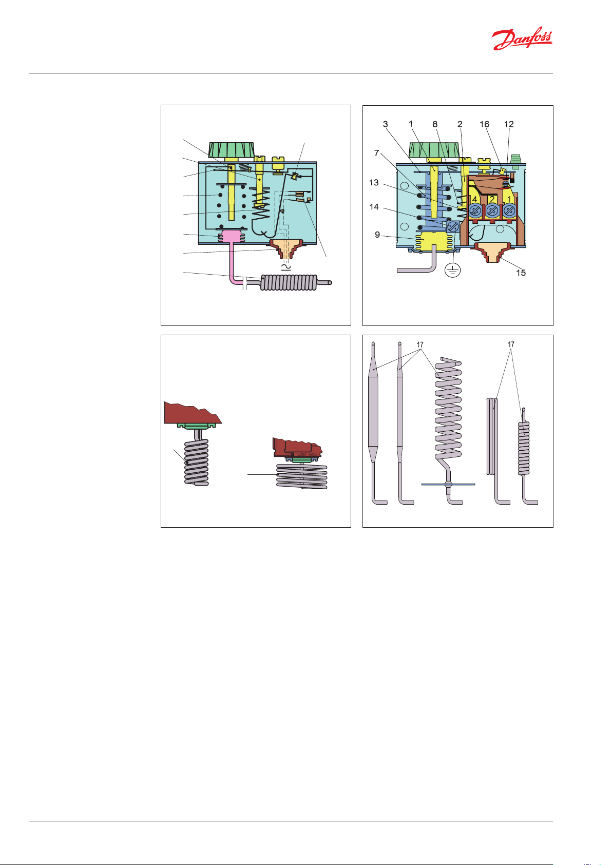
Design / function
1. Temperature setting spindle
2. Differential setting spindle
3. Main arm
7. Main spring
8. Differential spring
9. Bellows
12. Switch
13. Terminals
14. Earth terminal
15. Cable entr y
16. Tumbler
17. Sensor
Key sketch of KP thermostat KP thermostat
1
16
2
3
7
1
4
Danfoss
60-296.16
2
8
9
15
17
12
Danfoss
Adsorption charge
Vapour charge
The switch in the KP has a snap-action function
and the bellows move only when the cut-in or
cut-out value is reached.
oss
Adsorption charge
The design of the KP thermostats affords the
following advantages:
y high contact load,
y ultra-short bounce time,
y vibration resistance up to 4 g,
in the range 0 – 1000 Hz,
y long mechanical and electrical life.
Vapour charge
10 | AF237586440562en-000405
© Danfoss | DCS (mwa) | 2018.10

Thermostat, type KP
60-421.13
Design / function
(continued)
1. Temperature setting spindle, OIL
3. Main arm
5. Temperature setting spindle, HT
7. Main spring
9. Bellows
10. Capillary tube, OIL
11. Capillary tube, HT
12. Switch
13. Terminals
14. Earth terminal
15. Cable entry
16. Tumbler
17. Sensor (bulb)
18. Locking plate
KP thermostat, dual type
Dual thermostat KP 98 is used to provide
protection against excessively high discharge
gas temperature and to ensure a suitable oil
temperature in the compressor.
To avoid the temperature of the hot gas
exceeding the maximum permissible value
during extreme operating conditions (low
evaporating pressure, high condensing pressure,
high suction vapour superheat) a KP 98
thermostat can be used on the high temperature
side (HT). If the temperature of the hot gas
becomes too high the refrigerant will break down
and the compressor discharge valve will become
damaged.
Danfoss
60-370.16
Danfoss
The risk is greatest in refrigeration systems that
operate on a high compression ratio (e.g. in
systems with NH
hot gas bypass.
or R22) and in applications with
3
This unit has two separate thermostat functions.
The HT sensor that controls the discharge gas
temperature is fitted on the discharge tube
immediately after the compressor.
For larger compressors, the sensor can be built
into the discharge line.
The OIL sensor that controls the oil temperature
is located in the compressor oil sump.
Terminology
© Danfoss | DCS (mwa) | 2018.10
Differential
The differential is the difference between the
make and break temperatures.
A differential is necessary for satisfactory
automatic operation of the plant.
Mechanical differential (intrinsic differential)
The mechanical differential is the differential set
by the differential spindle.
Operating differential (thermal differential)
The operating differential is the differential
the plant operates on. Operating differential is
the sum of the mechanical differential and the
differential produced by the time constant.
Reset
1. Manual reset:
Units with manual reset can only be restarted
after the reset button has been activated.
On min. reset units the set value is equal to
the cut-out value for falling temperature.
On max. reset units the set value is equal to
the cut-out value for rising temperature.
2. Automatic reset:
These units are automatically reset after
operational stop.
AF237586440562en-000405 | 11

Thermostat, type KP
Setting
Charges
9. Bellows element
17. Sensor (bulb)
19. Capillary tube
Thermostats with automatic reset
Set the upper activating temperature on the
range scale.
Set the differential on the "DIFF" scale.
The temperature setting on the range scale will
then correspond to the temperature at which the
refrigeration compressor will be started on rising
temperature. The compressor will be stopped
when the temperature has fallen in relation to
the differential setting.
Note that the differential depends on the range
setting. Therefore, the differential scale
must only be used as guideline.
If with low stop temperature settings the
compressor will not stop, check whether the
differential is set at too high a value!
1. Vapour charge
Here the interdependence between the pressure
and temperature of saturated vapour is utilized,
i.e. the element is charged with saturated vapour
plus a small amount of liquid.
The charge is pressure-limited; a further increase
in pressure after evaporation of all the liquid in
the sensor (17) will only result in a small pressure
increase in the element.
Thermostats with minimum reset
Set the stop temperature on the range scale.
The differential is a fixed setting.
The compressor can be restarted by pressing
the “Reset button” after the temperature on the
thermostat sensor has risen by a value equal to
the fixed differential setting.
Thermostats with maximum reset
Set the stop temperature on the range scale.
The differential is a fixed setting.
The compressor can be restarted by pressing
the “Reset button” after the temperature on the
thermostat sensor has fallen to a value equal to
the fixed differential setting.
This principle can be utilized in thermostats for
low temperature, etc. where evaporation must
be able to take place from the free liquid surface
in the sensor (within the operating range of the
thermostat), and where at the same time, the
bellows must be protected against deformation
when kept at normal ambient temperatures.
Since the pressure in the element depends on
the temperature at the free liquid surface, the
thermostat must always be placed so that the
sensor is colder than the rest of the thermostatic
element.
The evaporated liquid will recondense at the
coldest point, i.e. the sensor. Thus, as intended,
the sensor becomes the temperature-controlling
part of the system.
Note: When the sensor is coldest, the ambient
temperature has no effect on regulating
accuracy.
9. Bellows element
17. Sensor (bulb)
19. Capillary tube
12 | AF237586440562en-000405
2. Adsorption charge
In this case the charge consists partly of a
superheated gas and partly of a solid having a
large adsorption surface.
The solid is concentrated in the sensor (17) and
it is therefore always the sensor that is the
temperature-controlling part of the thermostatic
element.
The sensor can be placed warmer or colder
than thermostat housing and capillary tube, but
variations from 20 °C ambient temperature will
influence the scale accuracy.
© Danfoss | DCS (mwa) | 2018.10
Thermostat, type KP
Danfoss
60-986.12
Danfoss
60-985.12
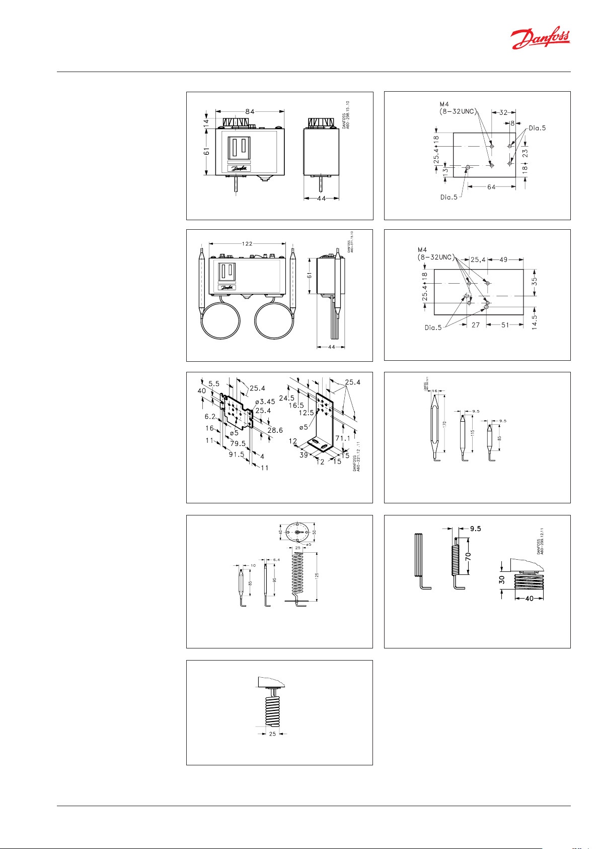
Dimensions [mm] and
weights [kg]
KP 61 – 81
KP 98
Wall bracket Angle bracket
Mounting holes (back of KP)
Mounting holes (back of KP)
D2: E2: E3:
KP 73 KP 71 KP 77, KP 73
KP 75, KP 77,
KP 98
© Danfoss | DCS (mwa) | 2018.10
D1: E1: F:
KP 73 KP 73 KP 75
KP 79
KP 81
C2:
KP 62
A: B: C1:
KP 61, KP 61, KP 62,
KP 63 KP 63, KP 68
KP 69
Net weight:
KP 61 – 81: approx. 0.4 kg
KP 98: approx. 0.6 kg
AF237586440562en-000405 | 13
 Loading...