

Page 1
MAKING MODERN LIVING POSSIBLE
Programming Guide
VLT® Automation VT Drive FC 322
Page 2

Page 3

VLTp Automation VT Drive FC322
Programming Guide
Contents
Contents
1 How to Programme
How to operate graphical LCP (GLCP) 4
Display Mode 11
Display Mode - Selection of Displayed Variables 11
How to operate numeric LCP (NLCP) 12
Parameter Set-Up 14
2 Parameter Description
Main Menu - Operation and Display - Group 0 22
Main Menu - Load and Motor - Group 1 40
Main Menu - Brakes - Group 2 52
Main Menu - Reference/Ramps - Group 3 55
Main Menu - Limits/Warnings - Group 4 65
Main Menu - Digital In/Out - Group 5 72
Main Menu - Analog In/Out - Group 6 99
Main Menu - Communications and Options - Group 8 111
Main Menu - Profibus - Group 9 120
Main Menu - CAN Fieldbus - Group 10 132
Main Menu - Smart Logic - Group 13 140
Main Menu - Special Functions - Group 14 157
Main Menu - Frequency Converter Information - Group 15 166
Main Menu - Data Readouts - Group 16 174
Main Menu - Data Readouts 2 - Group 18 184
Main Menu - FC Closed Loop - Group 20 186
Main Menu - Extended Closed Loop - Group 21 197
Main Menu - Application Functions - Group 22 211
Main Menu - Time-based Functions - Group 23 226
Main Menu - Cascade Controller - Group 25 240
Main Menu - Analog I/O Option MCB 109 - Group 26 254
Main menu – Water application – Group 29 264
Main Menu - Bypass Option - Group 31 266
3
21
3 Parameter Lists
Parameter Options 267
Default settings 267
Operation/Display 0-** 268
Load/Motor 1-** 270
MG.20.W1.22 - VLTp is a registered Danfoss trademark
267
1
Page 4

Contents
VLTp Automation VT Drive FC322
Programming Guide
Brakes 2-** 272
Reference / Ramps 3-** 273
Limits / Warnings 4-** 274
Digital In/Out 5-** 275
Analog In/Out 6-** 276
Comm. and Options 8-** 277
Profibus 9-** 278
CAN Fieldbus 10-** 279
Smart Logic 13-** 280
Special Functions 14-** 281
FC Information 15-** 282
Data Readouts 16-** 284
Data Readouts 2 18-** 286
FC Closed Loop 20-** 287
Ext. Closed Loop 21-** 288
Application Functions 22-** 290
Timed Actions 23-** 292
Cascade Controller 25-** 293
Analog I/O Option MCB 109 26-** 295
Cascade CTL Option 27-** 296
Water Application Functions 29-** 298
Bypass Option 31-** 299
2
MG.20.W1.22 - VLTp is a registered Danfoss trademark
Page 5
VLTp Automation VT Drive FC322
Programming Guide
1 How to Programme
1 How to Programme
VLT Automation VT Drive
FC 322
Software version: 1.7x
1
This guide can be used with all FC 322 frequency converters with
software version 1.7x or later.
The actual software version number can be read from
par. 15-43
Software Version
.
MG.20.W1.22 - VLTp is a registered Danfoss trademark
3
Page 6
1 How to Programme
1.1.1 How to operate graphical LCP (GLCP)
VLTp Automation VT Drive FC322
Programming Guide
1
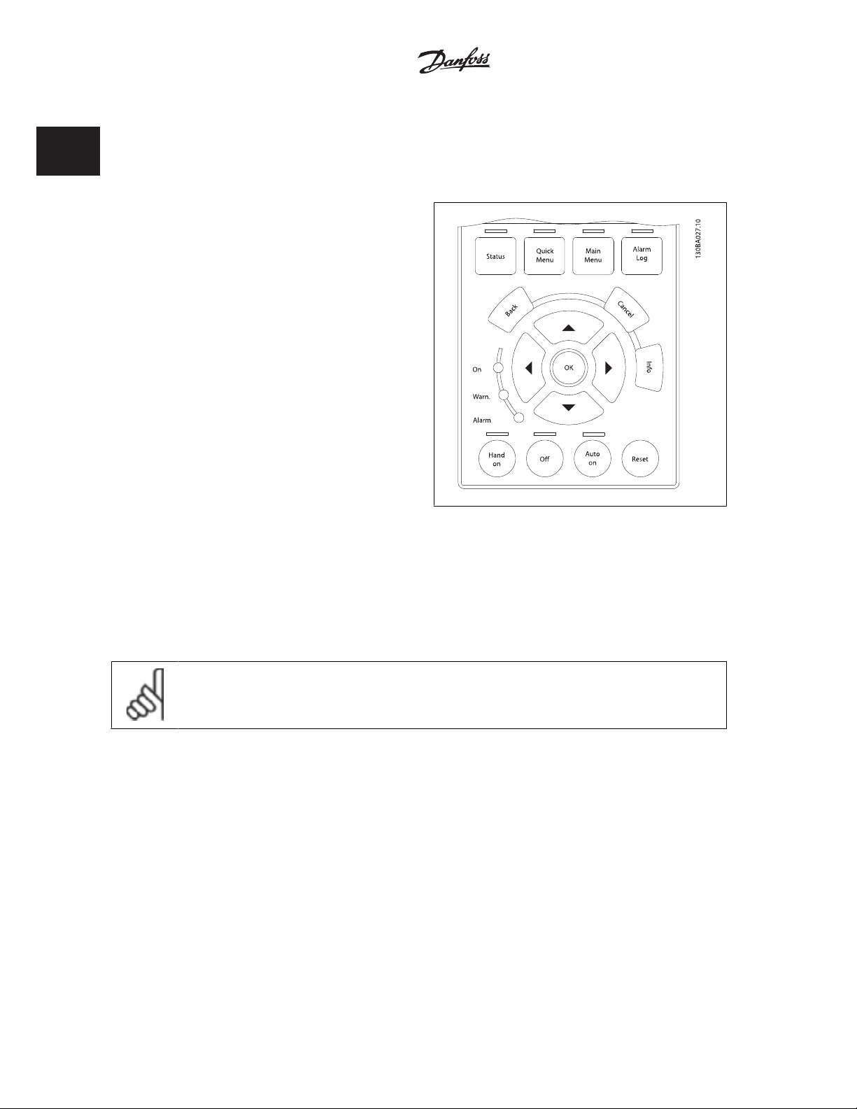
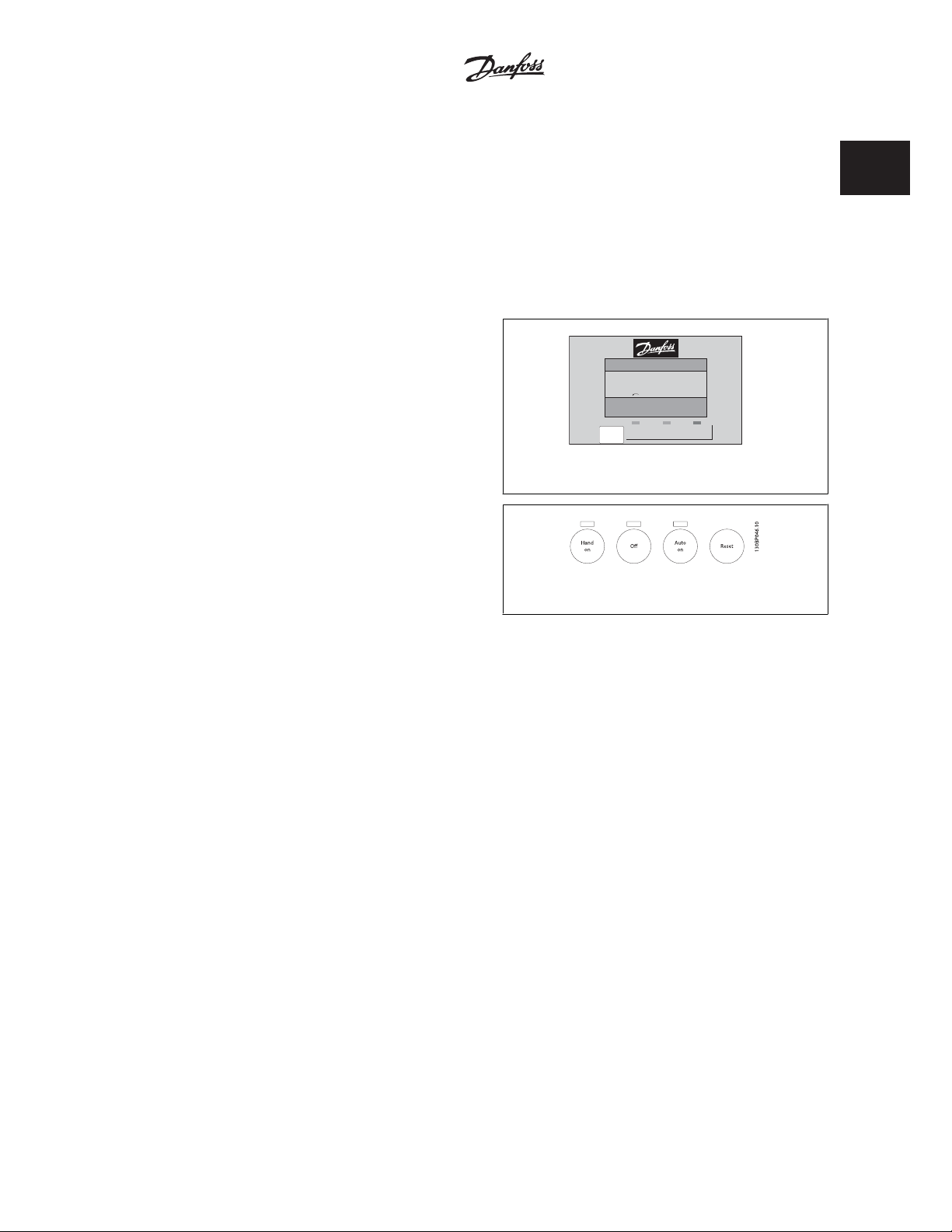
The following instructions are valid for the GLCP (LCP 102).
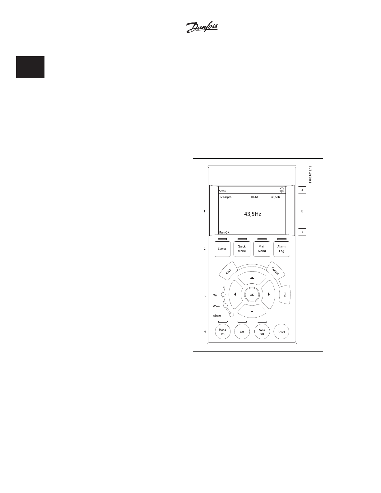
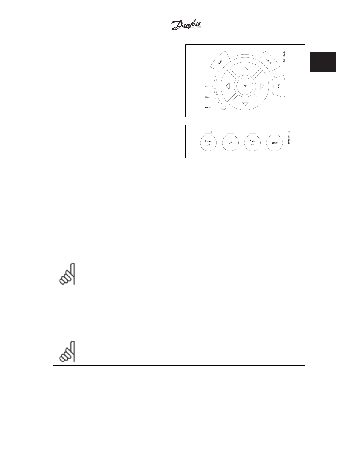
The GLCP is divided into four functional groups:
1. Graphical display with Status lines.
2. Menu keys and indicator lights (LED's) - selecting mode, changing parameters and switching between display functions.
3. Navigation keys and indicator lights (LEDs).
4. Operation keys and indicator lights (LEDs).
Graphical display:
The LCD-display is back-lit with a total of 6 alpha-numeric lines. All data is displayed on the LCP which can show up to five operating variables while in
[Status] mode.
Display lines:
a. Status line: Status messages displaying icons and graphics.
b. Line 1-2: Operator data lines displaying data and variables de-
fined or chosen by the user. By pressing the [Status] key, up to
one extra line can be added.
c. Status line: Status messages displaying text.
The display is divided into 3 sections:
Top section (a)
shows the status when in status mode or up to 2 variables when not in
status mode and in the case of Alarm/Warning.
The number of the Active Set-up (s elected as the Ac tive Set -up in pa r. 0-10) is shown . When programming in ano ther Set -up than the Active Set-up, the
number of the Set-up being programmed appears to the right in brackets.
Middle section (b)
shows up to 5 variables with related unit, regardless of status. In case of alarm/warning, the warning is shown instead of the variables.
It is possible to toggle between three status read-out displays by pressing the [Status] key.
Operating variables with different formatting are shown in each status screen - see below.
4
MG.20.W1.22 - VLTp is a registered Danfoss trademark
Page 7
VLTp Automation VT Drive FC322
Programming Guide
Several values or measurements can be linked to each of the displayed operating variables. The values / measurements to be displayed can be defined
via par. 0-20, 0-21, 0-22, 0-23, and 0-24, which can be accessed via [QUICK MENU], "Q3 Function Setups", "Q3-1 General Settings", "Q3-11 Display
Settings".
Each value / measurement readout parameter selected in par. 0-20 to par. 0-24 has its own scale and number of digits after a possible decimal point.
Larger numeric values are displayed with few digits after the decimal point.
Ex.: Current readout
5.25 A; 15.2 A 105 A.
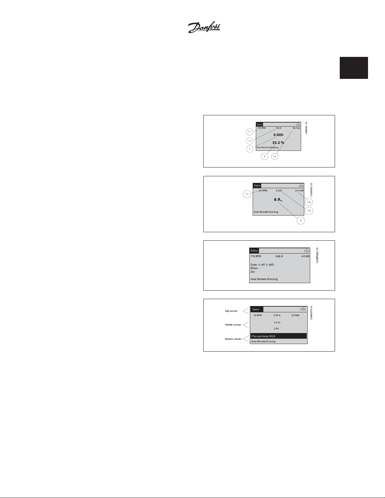
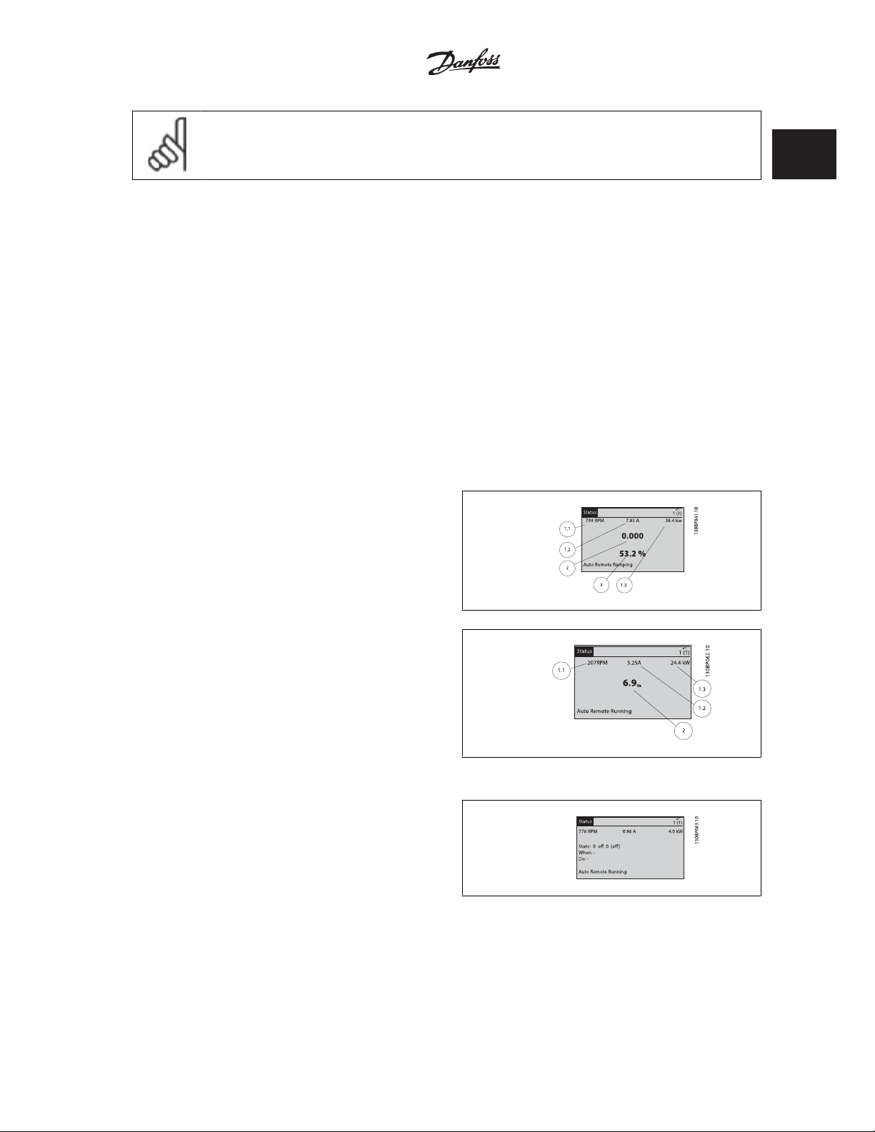
Status display I
This read-out state is standard after start-up or initialization.
Use [INFO] to obtain information about the value/measurement linked to
the displayed operating variables (1.1, 1.2, 1.3, 2, and 3).
See the operating variables shown in the display in this illustration. 1.1,
1.2 and 1.3 are shown in small size. 2 and 3 are shown in medium size.
Status display II
See the operating variables (1.1, 1.2, 1.3, and 2) shown in the display in
this illustration.
In the example, Speed, Motor current, Motor power and Frequency are
selected as variables in the first and second lines.
1.1, 1.2 and 1.3 are shown in small size. 2 is shown in large size.
1 How to Programme
1
Status display III:
This state displays the event and action of the Smart Logic Control. For
further information, see section
Bottom section
always shows the state of the frequency converter in Status mode.
Display Contrast Adjustment
Press [status] and [Ÿ] for darker display
Press [status] and [ź] for brighter display
Indicator lights (LEDs):
If certain threshold values are exceeded, the alarm and/or warning LED lights up. A status and alarm text appear on the control panel.
The On LED is activated when the frequency converter receives power from mains voltage, a DC bus terminal, or an external 24 V supply. At the same
time, the back light is on.
• Green LED/On: Control section is working.
• Yellow LED/Warn.: Indicates a warning.
Smart Logic Control
.
• Flashing Red LED/Alarm: Indicates an alarm.
MG.20.W1.22 - VLTp is a registered Danfoss trademark
5
Page 8

1
1 How to Programme
On
Warn.
Alarm
VLTp Automation VT Drive FC322
Programming Guide
0
1
.
4
4
0
P
B
0
3
1
6
MG.20.W1.22 - VLTp is a registered Danfoss trademark
Page 9

VLTp Automation VT Drive FC322
Programming Guide
GLCP keys
Menu keys
The menu keys are divided into functions. The keys below the display and
indicator lamps are used for parameter set-up, including choice of display
indication during normal operation.
[Status]
Indicates the status of the frequency converter and/or the motor. 3 different readouts can be chosen by pressing the [Status] key:
5 line readouts, 4 line readouts or Smart Logic Control.
Use [Status] for selecting the mode of display or for changing back to Display mode from either the Quick Menu mode, the Main Menu mode or Alarm
mode. Also use the [Status] key to toggle single or double read-out mode.
[Quick Menu]
Allows quick set-up of the frequency converter. The most common functions can be programmed here.
The [Quick Menu] consists of:
- Q1: My Personal Menu
-Q2: Quick Setup
- Q3: Function Setups
- Q5: Changes Made
- Q6: Loggings
The Function set-up provides quick and easy access to all parameters required for the majority of water and wastewater applications including variable
torque, constant torque, pumps, dossing pumps, well pumps, booster pumps, mixer pumps, aeration blowers and other pump and fan applications.
Amongst other features it also includes parameters for selecting which variables to display on the LCP, digital preset speeds, scaling of analog references,
closed loop single zone and multi-zone applications and specific functions related to water and wastewater applications.
1 How to Programme
1
The Quick Menu parameters can be accessed immediately unless a password has been created via par. 0-60, 0-61, 0-65 or 0-66.
It is possible to switch directly between Quick Menu mode and Main Menu mode.
[Main Menu]
is used for programming all parameters.
The Main Menu parameters can be accessed immediately unless a password has been created via par. 0-60, 0-61, 0-65 or 0-66. For the majority of water
and wastewater applications it is not necessary to access the Main Menu parameters but instead the Quick Menu, Quick Setup and Function Setups
provides the simplest and quickest access to the typical required parameters.
It is possible to switch directly between Main Menu mode and Quick Menu mode.
Parameter shortcut can be carried out by pressing down the [Main Menu] key for 3 seconds. The parameter shortcut allows direct access to any
parameter.
[Alarm Log]
displays an Alarm list of the five latest alarms (numbered A1-A5). To obtain additional details about an alarm, use the arrow keys to manoeuvre to the
alarm number and press [OK]. Information is displayed about the condition of the frequency converter before it enters the alarm mode.
[Back]
reverts to the previous step or layer in the navigation structure.
[Cancel]
last change or command will be cancelled as long as the display has not been changed.
[Info]
displays information about a command, parameter, or function in any display window. [Info] provides detailed information when needed.
Exit Info mode by pressing either [Info], [Back], or [Cancel].
MG.20.W1.22 - VLTp is a registered Danfoss trademark
7
Page 10

1
1 How to Programme
VLTp Automation VT Drive FC322
Programming Guide
8
MG.20.W1.22 - VLTp is a registered Danfoss trademark
Page 11
VLTp Automation VT Drive FC322
Programming Guide
Navigation Keys
The four navigation arrows are used to navigate between the different
choices available in [Quick Menu], [Main Menu] and [Alarm Log].
Use the keys to move the cursor.
[OK]
is used for choosing a parameter marked by the cursor and for enabling
the change of a parameter.
Operation Keys
for local control are found at the bottom of the control panel.
[Hand On]
enables control of the frequency converter via the GLCP. [Hand on] also starts the motor, and it is now possible to give the motor speed reference by
means of the arrow keys. The key can be
The following control signals will still be active when [Hand on] is activated:
• [Hand on] - [Off] - [Auto on]
• Reset
• Coasting stop inverse (motor coasting to stop)
•Reversing
• Set-up select lsb - Set-up select msb
• Stop command from serial communication
•Quick stop
•DC brake
Enabled
[1] or
Disabled
[0] via par.
0-40 [Hand on] Key on LCP.
1 How to Programme
1
NB!
External stop signals activated by means of control signals or a serial bus will override a “start” command via the LCP.
[Off]
Enabled
[1] or
Disabled
stops the connected motor. The key can be
[Off] key is inactive the motor can only be stopped by disconnecting the mains supply.
[Auto On]
enables the frequency converter to be controlled via the control terminals and/or serial communication. When a start signal is applied on the control
terminals and/or the bus, the frequency converter will start. The key can be
NB!
An active HAND-OFF-AUTO signal via the digital inputs has higher priority than the control keys [Hand on] – [Auto on].
[Reset]
is used for resetting the frequency converter after an alarm (trip). The key can be
MG.20.W1.22 - VLTp is a registered Danfoss trademark
[0] via par.
0-41 [Off] key on LCP.
Enabled
[1] or
Disabled
Enabled
[1] or
If no external stop function is selected and the
[0] via par.
Disabled
0-42 [Auto on] key on LCP.
[0] via par. 0-43
Reset Keys on LCP
.
9
Page 12
1
VLTp Automation VT Drive FC322
1 How to Programme
The parameter shortcut
can be carried out by holding down the [Main Menu] key for 3 seconds. The parameter shortcut allows direct access to any parameter.
1.1.2 Quick Transfer of Parameter Settings between Multiple Frequency Converters
Once the set-up of a frequency converter is complete, we recommend
that you store the data in the LCP or on a PC via MCT 10 Set-up Software
Tool.
Programming Guide
Data storage in LCP:
1. Go to par. 0-50
2. Press the [OK] key
3. Select “All to LCP”
4. Press the [OK] key
All parameter settings are now stored in the LCP indicated by the progress bar. When 100% is reached, press [OK].
You can now connect the LCP to another frequency converter and copy the parameter settings to this frequency converter as well.
Data transfer from LCP to frequency converter:
1. Go to par. 0-50
2. Press the [OK] key
3. Select “All from LCP”
4. Press the [OK] key
The parameter settings stored in the LCP are now transferred to the frequency converter indicated by the progress bar. When 100% is reached, press
[OK].
LCP Copy
NB!
Stop the motor before performing this operation.
LCP Copy
10
MG.20.W1.22 - VLTp is a registered Danfoss trademark
Page 13
VLTp Automation VT Drive FC322
Programming Guide
NB!
Stop the motor before performing this operation.
1.1.3 Display Mode
In normal operation, up to 5 different operating variables can be indicated continuously in the middle section: 1.1, 1.2, and 1.3 as well as 2 and 3.
1.1.4 Display Mode - Selection of Displayed Variables
It is possible to toggle between three status read-out screens by pressing the [Status] key.
Operating variables with different formatting are shown in each status screen - see below.
Several measurements can be linked to each of the operating variables. Define the links via par. 0-20, 0-21, 0-22, 0-23, and 0-24.
Each readout parameter selected in par. 0-20 to par. 0-24 has its own scale and digits after a possible decimal point. By larger numeric value of a parameter
fewer digits are displayed after the decimal point.
Ex.: Current readout below: 5.25 A; 15.2 A 105 A.
1 How to Programme
1
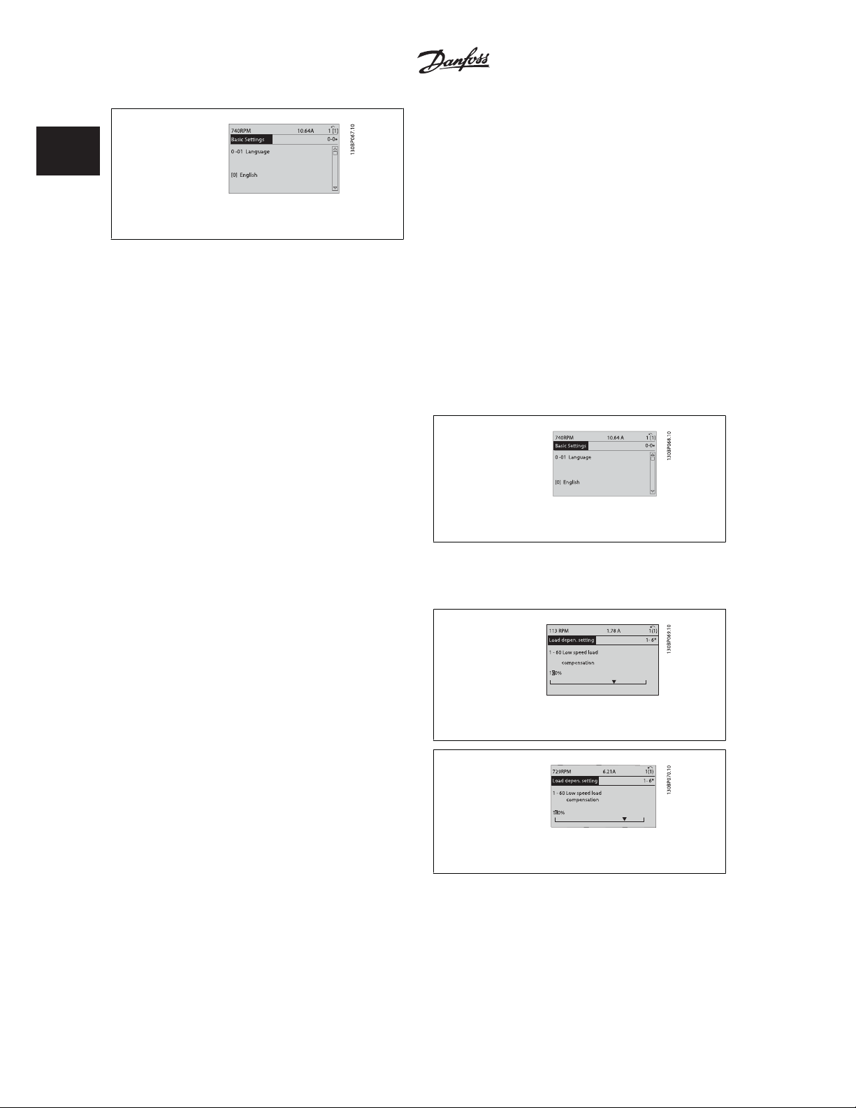
Status screen I
This read-out state is standard after start-up or initialization.
Use [INFO] to obtain information about the measurement links to the
displayed operating variables /1.1, 1.2, 1.3, 2, and 3).
See the operating variables shown in the screen in this illustration. 1.1,
1.2 and 1.3 are shown in small size. 2 and 3 are shown in medium size.
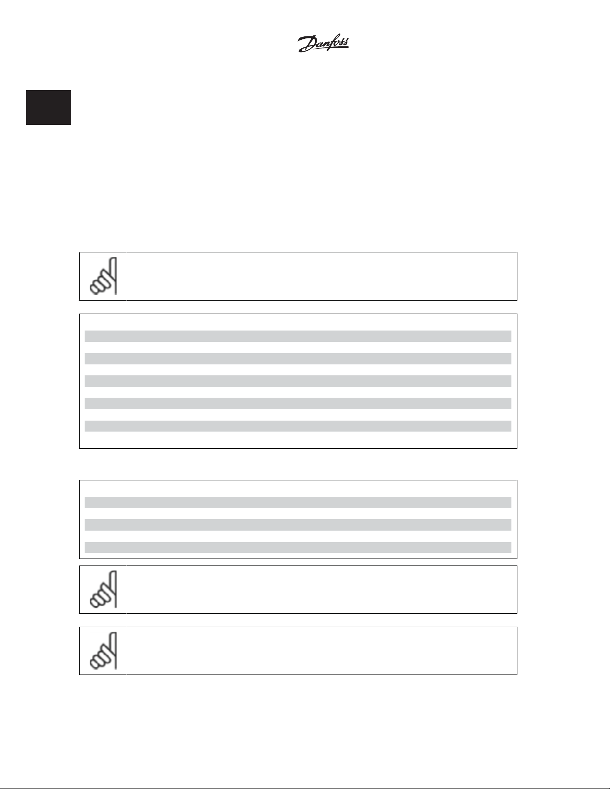
Status screen II:
See the operating variables (1.1, 1.2, 1.3, and 2) shown in the screen in
this illustration.
In the example, Speed, Motor current, Motor power and Frequency are
selected as variables in the first and second.
1.1, 1.2 and 1.3 are shown in small size. 2 is shown in large size.
In both status screen I and II it is possible to select other operating var-
iables by pressing
Status screen III:
This state displays the event and action of the Smart Logic Control. For
further information, see section
Ⴃ
or Ⴍ.
Smart Logic Control
.
MG.20.W1.22 - VLTp is a registered Danfoss trademark
11
Page 14
1 How to Programme
1.1.5 How to operate numeric LCP (NLCP)
VLTp Automation VT Drive FC322
Programming Guide
1
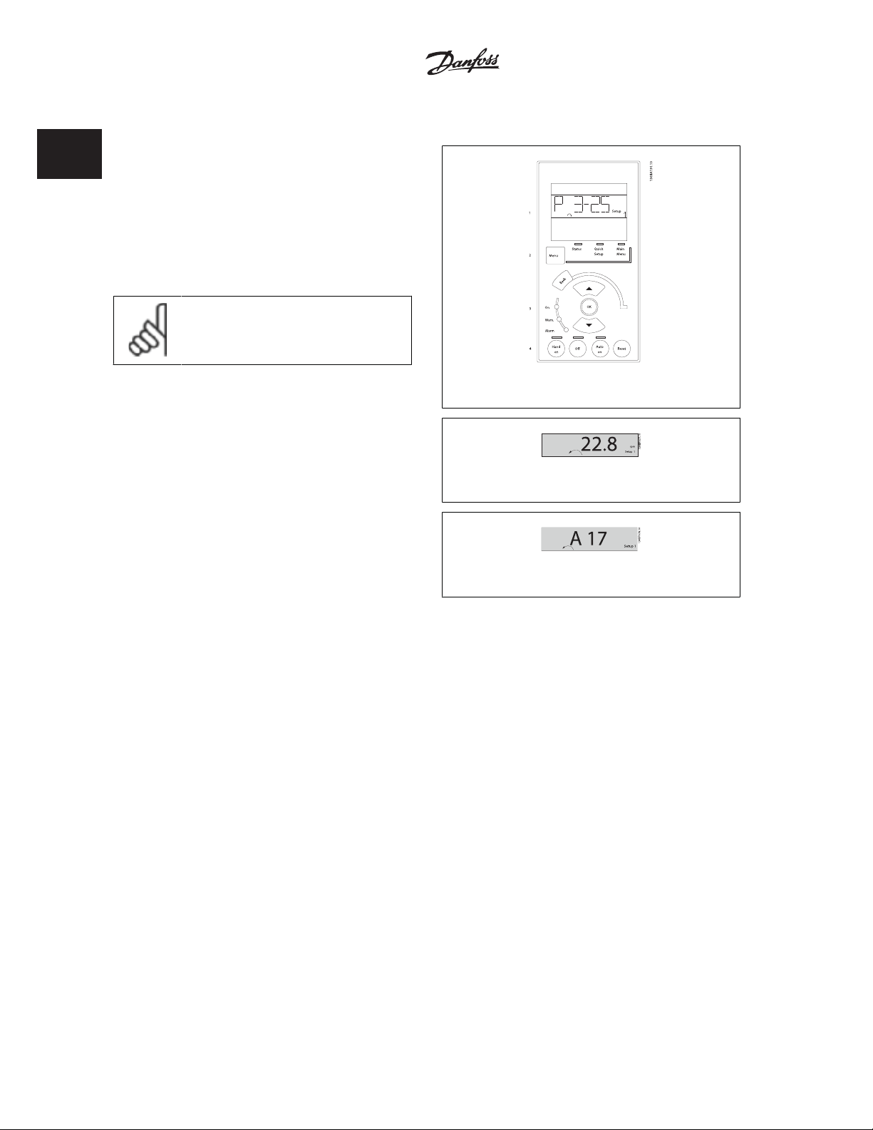
The following instructions are valid for the NLCP (LCP 101).
The control panel is divided into four functional groups:
1. Numeric display.
2. Menu key and indicator lights (LEDs) - changing parameters and
switching between display functions.
3. Navigation keys and indicator lights (LEDs).
4. Operation keys and indicator lights (LEDs).
NB!
Parameter copy is not possible with Numeric Local
Control Panel (LCP101).
Select one of the following modes:
Status Mode: Displays the status of the frequency converter or the mo-
tor.
If an alarm occurs, the NLCP automatically switches to status mode.
A number of alarms can be displayed.
Quick Setup or Main Menu Mode: Display parameters and parameter
settings.
Illustration 1.1: Numerical LCP (NLCP)
Illustration 1.2: Status display example
Illustration 1.3: Alarm display example
Indicator lights (LEDs):
• Green LED/On: Indicates if control section is on.
• Yellow LED/Wrn.: Indicates a warning.
• Flashing red LED/Alarm: Indicates an alarm.
Menu key
[Menu] Select one of the following modes:
•Status
•Quick Setup
• Main Menu
12
MG.20.W1.22 - VLTp is a registered Danfoss trademark
Page 15
Ⴃ
VLTp Automation VT Drive FC322
Programming Guide
Main Menu
is used for programming all parameters.
The parameters can be accessed immediately unless a password has been created via par. 0-60
] [Ⴍ]
, par. 0-65
w/o Password
Quick Setup is used to set up the frequency converter using only the most essential parameters.
The parameter values can be changed using the up/down arrows when the value is flashing.
Select Main Menu by pressing the [Menu] key a number of times until the Main Menu LED is lit.
Select the parameter group [xx-__] and press [OK]
Select the parameter [__-xx] and press [OK]
If the parameter is an array parameter select the array number and press [OK]
Select the wanted data value and press [OK]
Navigation Keys
[Back]
for stepping backwards
Arrow [
keys are used for manoeuvring between parameter groups, parameters
and within parameters
[OK]
is used for choosing a parameter marked by the cursor and for enabling
the change of a parameter.
Personal Menu Password
or par. 0-66
Access to Personal Menu w/o Password
Illustration 1.4: Display example
Main Menu Password
.
P 2-03
S ta tus Q uick
M enu
S etup
1 How to Programme
, par. 0-61
S etup 1
M ain
M enu
Access to Main Menu
130BP079.10
1
Operation Keys
Keys for local control are found at the bottom of the control panel.
Illustration 1.5: Operation keys of the numerical LCP (NLCP)
[Hand on]
enables control of the frequency converter via the LCP. [Hand on] also starts the motor and it is now possible to enter the motor speed data by means
of the arrow keys. The key can be
External stop signals activated by means of control signals or a serial bus will override a 'start' command via the LCP.
The following control signals will still be active when [Hand on] is activated:
• [Hand on] - [Off] - [Auto on]
• Reset
• Coasting stop inverse
•Reversing
• Set-up select lsb - Set-up select msb
• Stop command from serial communication
•Quick stop
•DC brake
[Off]
stops the connected motor. The key can be
If no external stop function is selected and the [Off] key is inactive the motor can be stopped by disconnecting the mains supply.
Enabled
[1] or
Enabled
Disabled
[1] or
[0] via par. 0-40
Disabled
[0] via par. 0-41
[Hand on] Key on LCP
[Off] Key on LCP
.
.
[Auto on]
enables the frequency converter to be controlled via the control terminals and/or serial communication. When a start signal is applied on the control
Enabled
[1] or
Disabled
terminals and/or the bus, the frequency converter will start. The key can be
MG.20.W1.22 - VLTp is a registered Danfoss trademark
[0] via par. 0-42
[Auto on] Key on LCP
.
13
Page 16
1
VLTp Automation VT Drive FC322
1 How to Programme
NB!
An active HAND-OFF-AUTO signal via the digital inputs has higher priority than the control keys [Hand on] [Auto on].
[Reset]
Enabled
[1] or
Disabled
is used for resetting the frequency converter after an alarm (trip). The key can be
1.1.6 Parameter Set-Up
The frequency converter can be used for practically all assignments, thus offering a significant number of parameters. The series offers a choice between
two programming modes - a Quick Menu mode and a Main Menu mode.
The latter provides access to all parameters. The former takes the user through a few parameters making it possible to program the majority of
water/ wastewater applications.
Regardless of the mode of programming, you can change a parameter both in the Quick Menu mode and in the Main Menu mode.
1.1.7 Quick Menu Mode
The GLCP provides access to all parameters listed under the Quick Menus. To set parameters using the [Quick Menu] button:
[0] via par. 0-43
Programming Guide
[Reset] Key on LCP
.
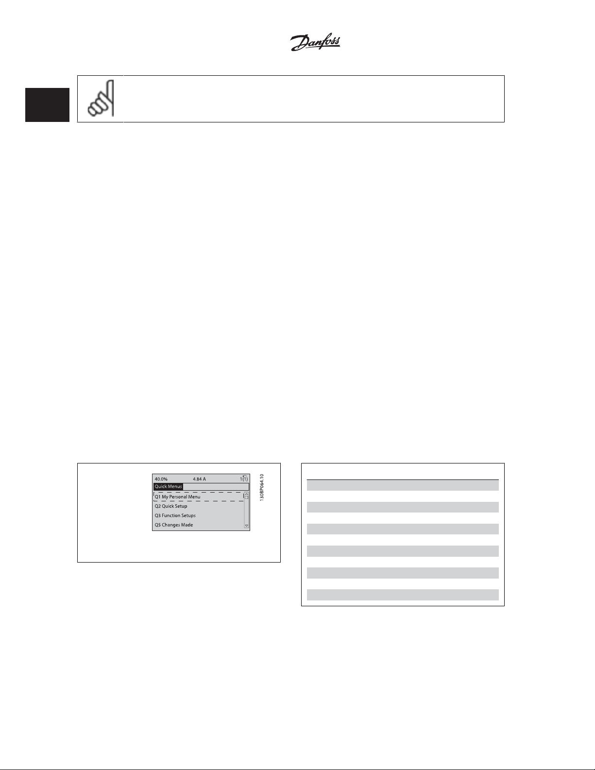
Pressing [Quick Menu] the list indicates the different areas contained in the Quick menu.
Efficient Parameter Set-up for Water Applications
The parameters can easily be set up for the vast majority of the water and wastewater applications only by using the [Quick Menu].
The optimum way to set parameters through the [Quick Menu] is by following the below steps:
1. Press [Quick Setup] for selecting basic motor settings, ramp times, etc.
2. Press [Function Setups] for setting up the required functionality of the frequency converter - if not already covered by the settings in [Quick
Setup].
3. Choose between
It is recommended to do the set-up in the order listed.
Illustration 1.6: Quick menu view.
General Settings, Open Loop Settings
and
Closed Loop Settings.
Par. Designation [Units]
0-01 Language
1-20 Motor Power [kW]
1-22 Motor Voltage [V]
1-23 Motor Frequency [Hz]
1-24 Motor Current [A]
1-25 Motor Nominal Speed [RPM]
3-41 Ramp 1 Ramp up Time [s]
3-42 Ramp 1 Ramp down Time [s]
4-11 Motor Speed Low Limit [RPM]
4-13 Motor Speed High Limit [RPM]
1-29 Automatic Motor Adaptation (AMA)
No Operation
If
Coast Inverse
If
14
Table 1.1: Quick Setup parameters
is selected in terminal 27 no connection to +24 V on terminal 27 is necessary to enable start.
(factory default value) is selected in Terminal 27, a connection to +24V is necessary to enable start.
MG.20.W1.22 - VLTp is a registered Danfoss trademark
Page 17
VLTp Automation VT Drive FC322
Programming Guide
NB!
For detailed parameter descriptions, please see the following section on
1.1.8 Q3 Function Setups
The Function Setup provides quick and easy access to all parameters required for the majority of water and wastewater applications including variable
torque, constant torque, pumps, dossing pumps, well pumps, booster pumps, mixer pumps, aeration blowers and other pump and fan applications.
Amongst other features it also includes parameters for selecting which variables to display on the LCP, digital preset speeds, scaling of analog references,
closed loop single zone and multi-zone applications and specific functions related to water and wastewater applications.
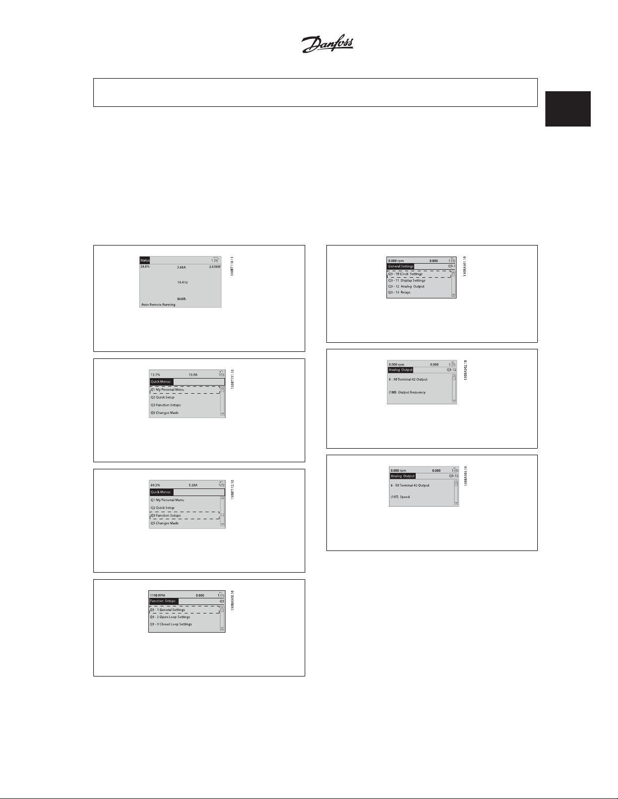
How to access Function Set-up - example:
Commonly Used Parameters - Explanations
.
1 How to Programme
1
Illustration 1.7: Step 1: Turn on the frequency converter (On
LED lights)
Illustration 1.8: Step 2: Press the [Quick Menus] button
(Quick Menus choices appear).
Illustration 1.9: Step 3: Use the up/down navigation keys to
scroll down to Function Setups. Press [OK].
Illustration 1.11: Step 5: Use the up/down navigation keys
to scroll down to i.e. 03-12
Illustration 1.12: Step 6: Choose parameter 6-50
42 Output
. Press [OK].
Illustration 1.13: Step 7: Use the up/down navigation keys
to select between the different choices. Press [OK].
Analog Outputs
. Press [OK].
Terminal
Illustration 1.10: Step 4: Function Setups choices appear.
Choose 03-1
General Settings
. Press [OK].
MG.20.W1.22 - VLTp is a registered Danfoss trademark
15
Page 18
1 How to Programme
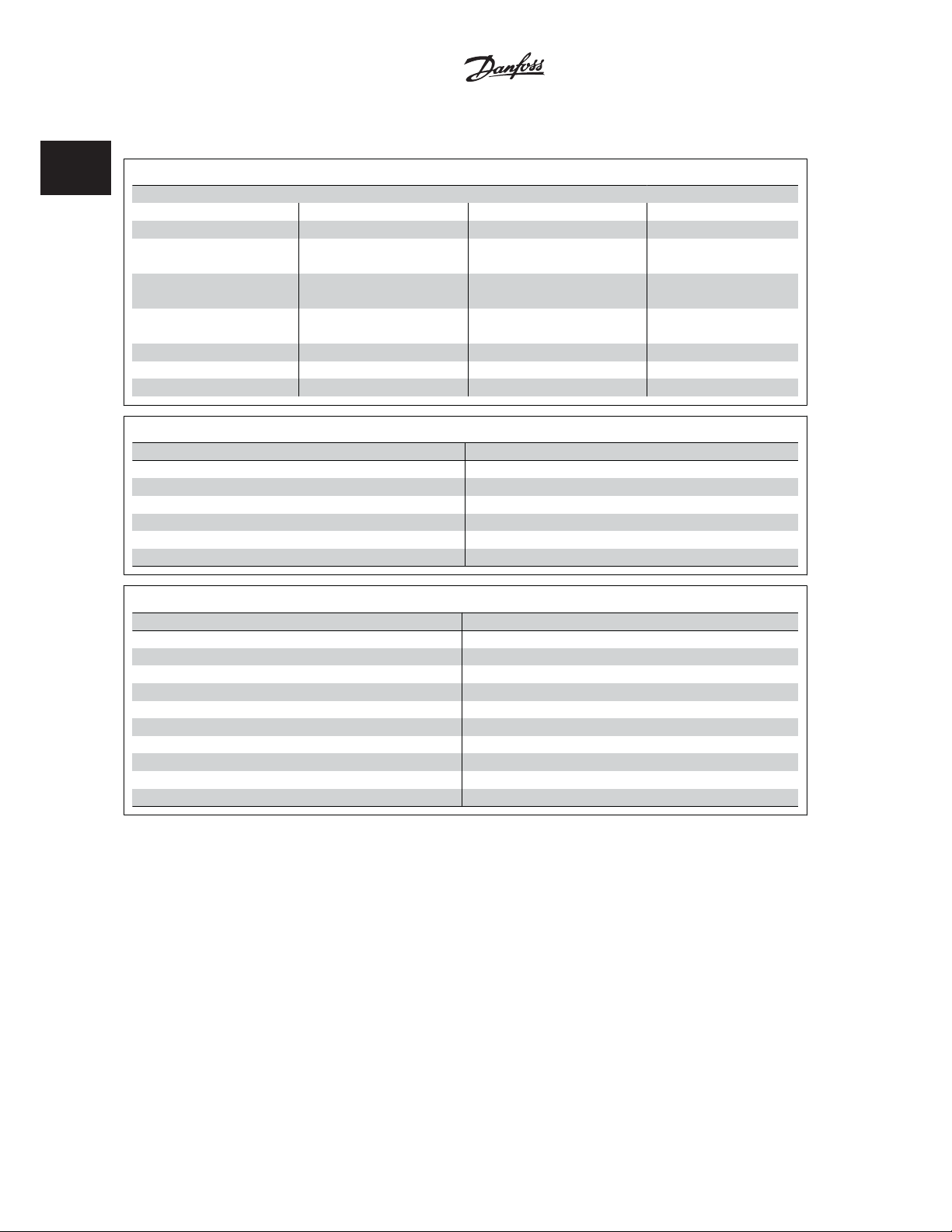
The Function Setup parameters are grouped in the following way:
VLTp Automation VT Drive FC322
Programming Guide
1
Q3-1 General Settings
Q3-10 Clock Settings Q3-11 Display Settings Q3-12 Analog Output Q3-13 Relays
0-70 Set Date and Time 0-20 Display Line 1.1 Small 6-50 Terminal 42 Output Relay 1 ය 5-40 Function Relay
0-71 Date Format 0-21 Display Line 1.2 Small 6-51 Terminal 42 Output Min Scale Relay 2 ය 5-40 Function Relay
0-72 Time Format 0-22 Display Line 1.3 Small 6-52 Terminal 42 Output Max Scale Option relay 7 ය 5-40 Function
Relay
0-74 DST/Summertime 0-23 Display Line 2 Large Option relay 8 ය 5-40 Function
Relay
0-76 DST/Summertime Start 0-24 Display Line 3 Large Option relay 9 ය 5-40 Function
Relay
0-77 DST/Summertime End 0-37 Display Text 1
0-38 Display Text 2
0-39 Display Text 3
Q3-2 Open Loop Settings
Q3-20 Digital Reference Q3-21 Analog Reference
3-02 Minimum Reference 3-02 Minimum Reference
3-03 Maximum Reference 3-03 Maximum Reference
3-10 Preset Reference 6-10 Terminal 53 Low Voltage
5-13 Terminal 29 Digital Input 6-11 Terminal 53 High Voltage
5-14 Terminal 32 Digital Input 6-14 Terminal 53 Low Ref/Feedb. Value
5-15 Terminal 33 Digital Input 6-15 Terminal 53 High Ref/Feedb. Value
Q3-3 Closed Loop Settings
Q3-30 Feedback Settings Q3-31 PID Settings
1-00 Configuration Mode 20-81 PID Normal/Inverse Control
20-12 Reference/Feedb.Unit 20-82 PID Start Speed [RPM]
3-02 Minimum Reference 20-21 Setpoint 1
3-03 Maximum Reference 20-93 PID Proportional Gain
6-20 Terminal 54 Low Voltage 20-94 PID Integral Time
6-21 Terminal 54 High Voltage
6-24 Terminal 54 Low Ref/Feedb Value
6-25 Terminal 54 High Ref/Feedb Value
6-00 Live Zero Timeout Time
6-01 Live Zero Timeout Function
16
MG.20.W1.22 - VLTp is a registered Danfoss trademark
Page 19

VLTp Automation VT Drive FC322
Programming Guide
1.1.9 Main Menu Mode
1 How to Programme
Both the GLCP and NLCP provide access to the main menu mode. Select
the Main Menu mode by pressing the [Main Menu] key. Illustration 6.2
shows the resulting read-out, which appears on the display of the GLCP.
Lines 2 through 5 on the display show a list of parameter groups which
can be chosen by toggling the up and down buttons.
Illustration 1.14: Display example.
Each parameter has a name and number which remain the same regardless of the programming mode. In the Main Menu mode, the parameters are
divided into groups. The first digit of the parameter number (from the left) indicates the parameter group number.
All parameters can be changed in the Main Menu. The configuration of the unit (par. 1-00
for programming. For example, selecting Closed Loop enables additional parameters related to closed loop operation. Option cards added to the unit
enable additional parameters associated with the option device.
Configuration Mode
) will determine other parameters available
1.1.10 Parameter Selection
In the Main Menu mode, the parameters are divided into groups. Select
a parameter group by means of the navigation keys.
The following parameter groups are accessible:
Group no. Parameter group:
0 Operation/Display
1Load/Motor
2 Brakes
3 References/Ramps
4 Limits/Warnings
5Digital In/Out
6 Analog In/Out
8 Comm. and Options
9 Profibus
10 CAN Fieldbus
11 LonWorks
13 Smart Logic
14 Special Functions
15 Drive Information
16 Data Readouts
18 Data Readouts 2
20 Drive Closed Loop
21 Ext. Closed Loop
22 Application Functions
23 Time-based Functions
24 Fire Mode
25 Cascade Controller
26 Analog I/O Option MCB 109
1
After selecting a parameter group, choose a parameter by means of the
navigation keys.
The middle section on the GLCP display shows the parameter number and
name as well as the selected parameter value.
MG.20.W1.22 - VLTp is a registered Danfoss trademark
Table 1.2: Parameter groups.
17
Page 20
1
VLTp Automation VT Drive FC322
1 How to Programme
Illustration 1.15: Display example.
1.1.11 Changing Data
The procedure for changing data is the same whether you select a parameter in the Quick menu or the Main menu mode. Press [OK] to change the
selected parameter.
The procedure for changing data depends on whether the selected parameter represents a numerical data value or a text value.
1.1.12 Changing a Text Value
If the selected parameter is a text value, change the text value by means
of the up/down navigation keys.
The up key increases the value, and the down key decreases the value.
Place the cursor on the value to be saved and press [OK].
Programming Guide
1.1.13 Changing a Group of Numeric Data Values
If the chosen parameter represents a numeric data value, change the
chosen data value by means of the [Ⴕ] and [Ⴋ] navigation keys as well
as the up/down [
keys to move the cursor horizontally.
Use the up/down navigation keys to change the data value. The up key
enlarges the data value, and the down key reduces the data value. Place
the cursor on the value to be saved and press [OK].
] [Ⴍ] navigation keys. Use the Ⴕ] and [Ⴋ] navigation
Ⴃ
Illustration 1.16: Display example.
Illustration 1.17: Display example.
Illustration 1.18: Display example.
18
MG.20.W1.22 - VLTp is a registered Danfoss trademark
Page 21

VLTp Automation VT Drive FC322
Programming Guide
1.1.14 Changing of Data Value, Step-by-Step
1 How to Programme
Certain parameters can be changed step by step or infinitely variably. This applies to par. 1-20
par. 1-23
Motor Frequency
The parameters are changed both as a group of numeric data values and as numeric data values infinitely variably.
.
Motor Power [kW]
, par. 1-22
Motor Voltage
and
1.1.15 Read-out and Programming of Indexed Parameters
Parameters are indexed when placed in a rolling stack.
par. 15-30
up/down navigation keys to scroll through the value log.
Use par. 3-10
Choose the parameter, press [OK], and use the up/down navigation keys keys to scroll through the indexed values. To change the parameter value,
select the indexed value and press [OK]. Change the value by using the up/down keys. Press [OK] to accept the new setting. Press [Cancel] to abort.
Press [Back] to leave the parameter.
Alarm Log: Error Code
Preset Reference
to par. 15-32
as another example:
Alarm Log: Time
contain a fault log which can be read out. Choose a parameter, press [OK], and use the
1
MG.20.W1.22 - VLTp is a registered Danfoss trademark
19
Page 22
1 How to Programme
1.1.16 Initialisation to Default Settings
VLTp Automation VT Drive FC322
Programming Guide
1
Initialise the frequency converter to default settings in two ways:
Recommended initialisation (via par. 14-22
1. Select par. 14-22
2. Press [OK]
3. Select “Initialisation”
4. Press [OK]
5. Cut off the mains supply and wait until the display turns off.
6. Reconnect the mains supply - the frequency converter is now reset.
7. Change par. 14-22
par. 14-22
par. 14-50
par. 8-30
par. 8-31
par. 8-32
par. 8-35
par. 8-36
par. 8-37
par. 15-00
par. 15-20
par. 15-30
Operation Mode
RFI Filter
Protocol
Address
Baud Rate
Minimum Response Delay
Max Response Delay
Maximum Inter-Char Delay
Operating Hours
Historic Log: Event
Alarm Log: Error Code
Operation Mode
Operation Mode
NB!
Resets parameters selected in Personal Menu with default factory setting.
initialises all except:
to par. 15-05
to par. 15-22
to par. 15-32
Operation Mode
back to
Normal Operation
Over Volt's
Historic Log: Time
Alarm Log: Time
)
.
Manual initialisation
1. Disconnect from mains and wait until the display turns off.
2a. Press [Status] - [Main Menu] - [OK] at the same time while power up for LCP 102, Graphical Display
2b. Press [Menu] while power up for LCP 101, Numerical Display
3. Release the keys after 5 s.
4. The frequency converter is now programmed according to default settings.
This procedure initializes all except: par. 15-00
NB!
When you carry out manual initialisation, you also reset serial communication, par. 14-50
Removes parameters selected in par. 25-00
NB!
After initialization and power cycling, the display will not show any information until after a couple of minutes.
20
Operating Hours
; par. 15-03
Cascade Controller
MG.20.W1.22 - VLTp is a registered Danfoss trademark
Power Up's
.
; par. 15-04
Over Temp's
RFI Filter
; par. 15-05
and fault log settings.
Over Volt's
.
Page 23

VLTp Automation VT Drive FC322
Programming Guide
2 Parameter Description
2.1.1 Parameter Set-Up
2 Parameter Description
Overview of parameter groups
Group Title Function
0- Operation / Display Parameters related to the fundamental functions of the frequency converter, function of
the LCP buttons and configuration of the LCP display.
1- Load / Motor Parameter group for motor settings.
2- Brakes Parameter group for setting brake features in the frequency converter.
3- Reference / Ramps Parameters for reference handling, definitions of limitations, and configuration of the re-
action of the frequency converter to changes.
4- Limits / Warnings Parameter group for configuring limits and warnings.
5- Digital In/Out Parameter group for configuring the digital inputs and outputs.
6- Analog In/Out Parameter group for configuration of the analog inputs and outputs.
8- Communication and Options Parameter group for configuring communications and options.
9- Profibus Parameter group for Profibus-specific parameters.
10- DeviceNet Fieldbus Parameter group for DeviceNet-specific parameters.
13- Smart Logic Parameter group for Smart Logic Control
14- Special Functions Parameter group for configuring special frequency converter functions.
15- Drive Information Parameter group containing frequency converter information such as operating data,
hardware configuration and software versions.
16- Data Readouts Parameter group for data read-outs, e.g. actual references, voltages, control, alarm,
warning and status words.
18- Info and Readouts This parameter group contains the last 10 Preventive Maintenance logs.
20- Drive Closed Loop This parameter group is used for configuring the closed loop PID Controller that controls
the output frequency of the unit.
21- Extended Closed Loop Parameters for configuring the three Extended Closed Loop PID Controllers.
22- Application Functions These parameters monitor water applications.
23- Time-based Functions These parameters are for actions needed to be performed on a daily or weekly basis, e.g.
different references for working hours/non-working hours.
25- Basic Cascade Controller Functions Parameters for configuring the Basic Cascade Controller for sequence control of multiple
pumps.
26- Analog I/0 Option MCB 109 Parameters for configuring the Analog I/0 Option MCB 109.
27- Extended Cascade Control Parameters for configuring the Extended Cascade Control.
29- Water Application Functions Parameters for setting water specific functions.
31- Bypass Option Parameters for configuring the Bypass Option
2
Table 2.1: Parameter Groups
Parameter descriptions and selections are displayed on the graphic (GLCP) or numeric (NLCP) in the display area. (See Section 5 for details.) Access the
parameters by pressing the [Quick Menu] or [Main Menu] key on the control panel. The quick menu is used primarily for commissioning the unit at start-
up by providing those parameters necessary to start operation. The main menu provides access to all parameters for detailed application programming.
All digital input/output and analog input/output terminals are multifunctional. All terminals have factory default functions suitable for the majority of water
applications but if other special functions are required, they must be programmed in parameter group 5 or 6.
MG.20.W1.22 - VLTp is a registered Danfoss trademark
21
Page 24

2 Parameter Description
2.1 Main Menu - Operation and Display - Group 0
2.2.1 0-** Operation / Display
VLTp Automation VT Drive FC322
Programming Guide
2
Parameters related to the fundamental functions of the frequency converter, function of the LCP buttons and configuration of the LCP display.
2.2.2 0-0* Basic Settings
Parameter group for basic frequency converter settings.
0-01 Language
Option: Function:
Defines the language to be used in the display.
The frequency converter can be delivered with 2 different language packages. English and German
are included in both packages. English cannot be erased or manipulated.
[0] * English Part of Language packages 1 - 2
[1] Deutsch Part of Language packages 1 - 2
[2] Francais Part of Language package 1
[3] Dansk Part of Language package 1
[4] Spanish Part of Language package 1
[5] Italiano Part of Language package 1
[6] Svenska Part of Language package 1
[7] Nederlands Part of Language package 1
[10] Chinese Language package 2
[20] Suomi Part of Language package 1
[22] English US Part of Language package 1
[27] Greek Part of Language package 1
[28] Bras.port Part of Language package 1
[36] Slovenian Part of Language package 1
[39] Korean Part of Language package 2
[40] Japanese Part of Language package 2
[41] Turkish Part of Language package 1
[42] Trad.Chinese Part of Language package 2
[43] Bulgarian Part of Language package 1
[44] Srpski Part of Language package 1
[45] Romanian Part of Language package 1
[46] Magyar Part of Language package 1
[47] Czech Part of Language package 1
22
MG.20.W1.22 - VLTp is a registered Danfoss trademark
Page 25

VLTp Automation VT Drive FC322
Programming Guide
[48] Polski Part of Language package 1
[49] Russian Part of Language package 1
[50] Thai Part of Language package 2
[51] Bahasa Indonesia Part of Language package 2
[52] Hrvatski
0-02 Motor Speed Unit
Option: Function:
This parameter cannot be adjusted while the motor is running.
The display showing depends on settings in par. 0-02
Settings
. The default setting of par. 0-02
on which region of the world the frequency converter is supplied to, but can be re-programmed as
required.
NB!
Changing the
It is recommended to select the motor speed unit first, before modifying other
parameters.
[0] * RPM Selects display of motor speed variables and parameters (i.e. references, feedbacks and limits) in
terms of motor speed (RPM).
Motor Speed Unit
Motor Speed Unit
Motor Speed Unit
and par. 0-03
will reset certain parameters to their initial value.
2 Parameter Description
and par. 0-03
Regional Settings
Regional
depends
2
[1] * Hz Selects display of motor speed variables and parameters (i.e. references, feedbacks and limits) in
terms of output frequency to the motor (Hz).
0-03 Regional Settings
Option: Function:
This parameter cannot be adjusted while the motor is running.
The display showing depends on settings in par. 0-02
Settings
. The default setting of par. 0-02
on which region of the world the frequency converter is supplied to but can be re-programmed as
required.
[0] * International Sets par. 1-20
cy
[50 Hz].
[1] North America Sets par. 1-21
60 Hz.
The setting not used is made invisible.
Motor Power [kW]
Motor Power [HP]
Motor Speed Unit
Motor Speed Unit
units to [kW] and the default value of par. 1-23
units to HP and the default value of par. 1-23
and par. 0-03
and par. 0-03
Regional Settings
Motor Frequen-
Motor Frequency
Regional
depends
to
MG.20.W1.22 - VLTp is a registered Danfoss trademark
23
Page 26

2 Parameter Description
0-04 Operating State at Power-up
Option: Function:
Select the operating mode upon reconnection of the frequency converter to mains voltage after
power down when operating in Hand (local)mode.
VLTp Automation VT Drive FC322
Programming Guide
2
[0] * Resume Resumes operation of the frequency converter maintaining the same local reference and the same
start/stop condition (applied by [Hand On]/[Off] on the LCP or Hand Start via a digital input as
before the frequency converter was powered down.
[1] Forced stop, ref=old Uses saved reference [1] to stop the frequency converter but at the same time retain in memory
the local speed reference prior to power down. After mains voltage is reconnected and after re-
ceiving a start command (using the LCP [Hand On] button or Hand Start command via a digital
input) the frequency converter restarts and operates at the retained speed reference.
24
MG.20.W1.22 - VLTp is a registered Danfoss trademark
Page 27

VLTp Automation VT Drive FC322
Programming Guide
2.2.3 0-1* Set-up Operations
Define and control the individual parameter set-ups.
The frequency converter has four parameter setups that can be programmed independently of each other. This makes the frequency converter very
flexible and able to meet the requirements of many different system control schemes often saving the cost of external control equipment. For example
these can be used to program the frequency converter to operate according to one control scheme in one setup (e.g. daytime operation) and another
control scheme in another setup (e.g. night set back). Alternatively they can be used by an AHU or packaged unit OEM to identically program all their
factory fitted frequency converters for different equipment models within a range to have the same parameters and then during production/commissioning
simply select a specific setup depending on which model within that range the frequency converter is installed on.
The active setup (i.e. the setup in which the frequency converter is currently operating) can be selected in parameter 0-10 and is displayed in the LCP.
Using Multi set-up it is possible to switch between set-ups with the frequency converter running or stopped, via digital input or serial communication
commands (e.g. for night set back). If it is necessary to change setups whilst running, ensure parameter 0-12 is programmed as required. For the majority
of applications it will not be necessary to program parameter 0-12 even if change of set up whilst running is required, but for very complex applications,
using the full flexibility of the multiple setups, it may be required. Using parameter 0-11 it is possible to edit parameters within any of the setups whilst
continuing the frequency converter operation in its Active Setup which can be a different setup to that being edited. Using parameter 0-51 it is possible
to copy parameter settings between the set-ups to enable quicker commissioning if similar parameter settings are required in different set-ups.
0-10 Active Set-up
Option: Function:
Select the set-up in which the frequency converter is to operate.
Use par. 0-51
of the same parameter within two different set-ups, link the set-ups together using par. 0-12
Set-up Linked to
marked ‘not changeable during operation’ have different values.
Parameters which are ‘not changeable during operation’ are marked FALSE in the parameter lists in
the section
Set-up Copy
. Stop the frequency converter before switching between set-ups where parameters
Parameter Lists
to copy a set-up to one or all other set-ups. To avoid conflicting settings
2 Parameter Description
This
2
[0] Factory setup Cannot be changed. It contains the Danfoss data set, and can be used as a data source when
returning the other set-ups to a known state.
[1] * Set-up 1
[2] Set-up 2
[3] Set-up 3
[4] Set-up 4
[9] Multi Set-up Is used for remote selection of set-ups using digital inputs and the serial communication port. This
Set-up 1
[1] to
Set-up 4
[4] are the four separate parameter set-ups within which all parameters
can be programmed.
set-up uses the settings from par. 0-12
This Set-up Linked to
.
MG.20.W1.22 - VLTp is a registered Danfoss trademark
25
Page 28

2 Parameter Description
0-11 Programming Set-up
Option: Function:
Select the set-up to be edited (i.e. programmed) during operation; either the active set-up or one
of the inactive set-ups. The set-up number being edited is displayed in the LCP in (brackets).
VLTp Automation VT Drive FC322
Programming Guide
2
[0] Factory setup cannot be edited but it is useful as a data source to return the other set-ups to a known state.
[1] Set-up 1
[2] Set-up 2
[3] Set-up 3
[4] Set-up 4
[9] * Active Set-up (i.e. the set-up in which the frequency converter is operating) can also be edited during operation.
Set-up 1
[1] to
Set-up 4
[4] can be edited freely during operation, independently of the active set-
up.
Editing parameters in the chosen setup would normally be done from the LCP but it is also possible
from any of the serial communication ports.
0-12 This Set-up Linked to
Option: Function:
This parameter only needs to be programmed if changing set-ups is required whilst the motor is
running. It ensures that parameters which are "not changeable during operation" have the same
setting in all relevant set-ups.
To enable conflict-free changes from one set-up to another whilst the frequency converter is run-
ning, link set-ups containing parameters which are not changeable during operation. The link will
ensure synchronising of the ‘not changeable during operation’ parameter values when moving from
one set-up to another during operation. ‘Not changeable during operation’ parameters can be iden-
tified by the label FALSE in the parameter lists in the section
The par. 0-12
selected. Multi set-up can be used to move from one set-up to another during operation (i.e. while
the motor is running).
Example:
Use Multi set-up to shift from Set-up 1 to Set-up 2 whilst the motor is running. Programme param-
eters in Set-up 1 first, then ensure that Set-up 1 and Set-up 2 are synchronised (or ‘linked’). Syn-
chronisation can be performed in two ways:
1. Change the edit set-up to
Set-up Linked to
This Set-up Linked to
Set-up 2
to
Set-up 1
[1]. This will start the linking (synchronising) process.
feature is used when Multi set-up in par. 0-10
[2] in par. 0-11
Parameter Lists
Programming Set-up
.
Active Set-up
and set par. 0-12
This
is
26
OR
2. While still in Set-up 1, using par. 0-50
This Set-up Linked to
par. 0-12
MG.20.W1.22 - VLTp is a registered Danfoss trademark
to
Set-up 2
[2]. This will start the linking process.
LCP Copy
, copy Set-up 1 to Set-up 2. Then set
Page 29

VLTp Automation VT Drive FC322
Programming Guide
2 Parameter Description
2
After the link is complete, par. 0-13
changeable during operation’ parameters are now the same in Set-up 1 and Set-up 2. If there are
changes to a ‘not changeable during operation’ parameter, e.g. par. 1-30
Set-up 2, they will also be changed automatically in Set-up 1. A switch between Set-up 1 and Set-
up 2 during operation is now possible.
[0] * Not linked
[1] Set-up 1
[2] Set-up 2
[3] Set-up 3
[4] Set-up 4
Readout: Linked Set-ups
0-13 Readout: Linked Set-ups
Array [5]
Range: Function:
0* [0 - 255 ] View a list of all the set-ups linked by means of par. 0-12
one index for each parameter set-up. The parameter value displayed for each index represents
which setups are linked to that parameter setup.
Index LCP value
0 {0}
1 {1,2}
2 {1,2}
3{3}
4 {4}
will read {1,2} to indicate that all ‘not
Stator Resistance (Rs)
This Set-up Linked to
. The parameter has
, in
Table 2.3: Example: Set-up 1 and Set-up 2 are linked
0-14 Readout: Prog. Set-ups / Channel
Range: Function:
0* [-2147483648 - 2147483647 ] View the setting of par. 0-11
channels. When the number is displayed in hex, as it is in the LCP, each number represents one
channel.
Numbers 1-4 represent a set-up number; ‘F’ means factory setting; and ‘A’ means active set-up.
The channels are, from right to left: LCP, FC bus, USB, HPFB1.5.
Example: The number AAAAAA21h means that the FC bus selected Set-up 2 in par. 0-11
ming Set-up
, the LCP selected Set-up 1 and all others used the active set-up.
2.2.4 0-2* LCP Display
Define the variables displayed in the Graphical Local Control Panel.
MG.20.W1.22 - VLTp is a registered Danfoss trademark
Programming Set-up
for each of the four different communication
Program-
27
Page 30

2 Parameter Description
NB!
Please refer to par. 0-37
texts
Display Text 1
, par. 0-38
Display Text 2
and par. 0-39
Display Text 3
VLTp Automation VT Drive FC322
Programming Guide
for information on how to write display
2
0-20 Display Line 1.1 Small
Option: Function:
Select a variable for display in line 1, left position.
[0] None No display value selected
[37] Display Text 1 Present control word
[38] Display Text 2 Enables an individual text string to be written, for display in the LCP or to be read via serial com-
munication.
[39] Display Text 3 Enables an individual text string to be written, for display in the LCP or to be read via serial com-
munication.
[89] Date and Time Readout Displays the current date and time.
[953] Profibus Warning Word Displays Profibus communication warnings.
[1005] Readout Transmit Error Counter View the number of CAN control transmission errors since the last power-up.
[1006] Readout Receive Error Counter View the number of CAN control receipt errors since the last power-up.
[1007] Readout Bus Off Counter View the number of Bus Off events since the last power-up.
[1013] Warning Parameter View a DeviceNet-specific warning word. One separate bit is assigned to every warning.
[1115] LON Warning Word Shows the LON-specific warnings.
[1117] XIF Revision Shows the version of the external interface file of the Neuron C chip on the LON option.
[1118] LON Works Revision Shows the software version of the application program of the Neuron C chip on the LON option.
[1500] Operating Hours View the number of running hours of the frequency converter.
[1501] Running Hours View the number of running hours of the motor.
[1502] kWh Counter View the mains power consumption in kWh.
[1600] Control Word View the Control Word sent from the frequency converter via the serial communication port in hex
code.
[1601] * Reference [Unit] Total reference (sum of digital/analog/preset/bus/freeze ref./catch up and slow-down) in selected
unit.
[1602] Reference % Total reference (sum of digital/analog/preset/bus/freeze ref./catch up and slow-down) in percent.
[1603] Status Word Present status word
[1605] Main Actual Value [%] One or more warnings in a Hex code
[1609] Custom Readout View the user-defined readouts as defined in par. 0-30, 0-31 and 0-32.
[1610] Power [kW] Actual power consumed by the motor in kW.
[1611] Power [hp] Actual power consumed by the motor in HP.
[1612] Motor Voltage Voltage supplied to the motor.
[1613] Motor Frequency Motor frequency, i.e. the output frequency from the frequency converter in Hz.
[1614] Motor Current Phase current of the motor measured as effective value.
[1615] Frequency [%] Motor frequency, i.e. the output frequency from the frequency converter in percent.
[1616] Torque [Nm] Present motor load as a percentage of the rated motor torque.
[1617] Speed [RPM] Speed in RPM (revolutions per minute) i.e. the motor shaft speed in closed loop based on the entered
motor nameplate data, the output frequency and the load on the frequency converter.
[1618] Motor Thermal Thermal load on the motor, calculated by the ETR function. See also parameter group 1-9* Motor
Temperature.
28
MG.20.W1.22 - VLTp is a registered Danfoss trademark
Page 31

VLTp Automation VT Drive FC322
Programming Guide
[1622] Torque [%] Shows the actual torque produced, in percentage.
[1630] DC Link Voltage Intermediate circuit voltage in the frequency converter.
[1632] BrakeEnergy/s Present brake power transferred to an external brake resistor.
Stated as an instantaneous value.
[1633] BrakeEnergy/2 min Brake power transferred to an external brake resistor. The mean power is calculated continuously
for the most recent 120 seconds.
[1634] Heatsink Temp. Present heat sink temperature of the frequency converter. The cut-out limit is 95 ±5 oC; cutting
back in occurs at 70 ±5° C.
[1635] Thermal Drive Load Percentage load of the inverters
[1636] Inv. Nom. Current Nominal current of the frequency converter
[1637] Inv. Max. Current Maximum current of the frequency converter
[1638] SL Control State State of the event executed by the control
[1639] Control Card Temp. Temperature of the control card.
[1650] External Reference Sum of the external reference as a percentage, i.e. the sum of analog/pulse/bus.
[1652] Feedback [Unit] Signal value in units from the programmed digital input(s).
[1653] Digi Pot Reference View the contribution of the digital potentiometer to the actual reference Feedback.
[1654] Feedback 1 [Unit] View the value of Feedback 1. See also par. 20-0*.
[1655] Feedback 2 [Unit] View the value of Feedback 2. See also par. 20-0*.
[1656] Feedback 3 [Unit] View the value of Feedback 3. See also par. 20-0*.
[1658] PID Output [%] Returns the Drive Closed Loop PID controller output value in percent.
[1659] Adjusted Setpoint Displays the actual operating set-point after it is modified by flow compensation. See parameters
22-8*.
[1660] Digital Input Displays the status of the digital inputs. Signal low = 0; Signal high = 1.
Regarding order, see par. 16-60. Bit 0 is at the extreme right.
[1661] Terminal 53 Switch Setting Setting of input terminal 53. Current = 0; Voltage = 1.
[1662] Analog Input 53 Actual value at input 53 either as a reference or protection value.
[1663] Terminal 54 Switch Setting Setting of input terminal 54. Current = 0; Voltage = 1.
[1664] Analog Input 54 Actual value at input 54 either as reference or protection value.
[1665] Analog Output 42 [mA] Actual value at output 42 in mA. Use par. 6-50 to select the variable to be represented by output
42.
[1666] Digital Output [bin] Binary value of all digital outputs.
[1667] Freq. Input #29 [Hz] Actual value of the frequency applied at terminal 29 as a pulse input.
[1668] Freq. Input #33 [Hz] Actual value of the frequency applied at terminal 33 as a pulse input.
[1669] Pulse Output #27 [Hz] Actual value of pulses applied to terminal 27 in digital output mode.
[1670] Pulse Output #29 [Hz] Actual value of pulses applied to terminal 29 in digital output mode.
[1671] Relay Output [bin] View the setting of all relays.
[1672] Counter A View the present value of Counter A.
[1673] Counter B View the present value of Counter B.
[1675] Analog input X30/11 Actual value of the signal on input X30/11 (General Purpose I/O Card. Option)
[1676] Analog input X30/12 Actual value of the signal on input X30/12 (General Purpose I/O Card. Optional)
[1677] Analog output X30/8 [mA] Actual value at output X30/8 (General Purpose I/O Card. Optional) Use Par. 6-60 to select the var-
iable to be shown.
[1680] Fieldbus CTW 1 Control word (CTW) received from the Bus Master.
[1682] Fieldbus REF 1 Main reference value sent with control word via the serial communications network e.g. from the
BMS, PLC or other master controller.
2 Parameter Description
2
MG.20.W1.22 - VLTp is a registered Danfoss trademark
29
Page 32

2
VLTp Automation VT Drive FC322
2 Parameter Description
[1684] Comm. Option STW Extended fieldbus communication option status word.
[1685] FC Port CTW 1 Control word (CTW) received from the Bus Master.
[1686] FC Port REF 1 Status word (STW) sent to the Bus Master.
[1690] Alarm Word One or more alarms in a Hex code (used for serial communications)
[1691] Alarm Word 2 One or more alarms in a Hex code (used for serial communications)
[1692] Warning Word One or more warnings in a Hex code (used for serial communications)
[1693] Warning Word 2 One or more warnings in a Hex code (used for serial communications)
[1694] Ext. Status Word One or more status conditions in a Hex code (used for serial communications)
[1695] Ext. Status Word 2 One or more status conditions in a Hex code (used for serial communications)
[1696] Maintenance Word The bits reflect the status for the programmed Preventive Maintenance Events in parameter group
23-1*
[1830] Analog Input X42/1 Shows the value of the signal applied to terminal X42/1 on the Analog I/O card.
[1831] Analog Input X42/3 Shows the value of the signal applied to terminal X42/3 on the Analog I/O card.
[1832] Analog Input X42/5 Shows the value of the signal applied to terminal X42/5 on the Analog I/O card.
[1833] Analog Out X42/7 [V] Shows the value of the signal applied to terminal X42/7 on the Analog I/O card.
[1834] Analog Out X42/9 [V] Shows the value of the signal applied to terminal X42/9 on the Analog I/O card.
[1835] Analog Out X42/11 [V] Shows the value of the signal applied to terminal X42/11 on the Analog I/O card.
[2117] Ext. 1 Reference [Unit] The value of the reference for extended Closed Loop Controller 1
[2118] Ext. 1 Feedback [Unit] The value of the feedback signal for extended Closed Loop Controller 1
[2119] Ext. 1 Output [%] The value of the output from extended Closed Loop Controller 1
[2137] Ext. 2 Reference [Unit] The value of the reference for extended Closed Loop Controller 2
[2138] Ext. 2 Feedback [Unit] The value of the feedback signal for extended Closed Loop Controller 2
[2139] Ext. 2 Output [%] The value of the output from extended Closed Loop Controller 2
[2157] Ext. 3 Reference [Unit] The value of the reference for extended Closed Loop Controller 3
[2158] Ext. 3 Feedback [Unit] The value of the feedback signal for extended Closed Loop Controller 3
[2159] Ext. Output [%] The value of the output from extended Closed Loop Controller 3
[2230] No-Flow Power The calculated No Flow Power for the actual operating speed
[2580] Cascade Status Status for the operation of the Cascade Controller
[2581] Pump Status Status for the operation of each individual pump controlled by the Cascade Controller
[2791] Cascade Reference Reference output for use with follower drives.
[2792] % Of Total Capacity Readout parameter to show the system operating point as a % capacity of total system capacity.
[2793] Cascade Option Status Readout parameter to show the status of the cascade system.
Programming Guide
0-21 Display Line 1.2 Small
Option: Function:
Select a variable for display in line 1, middle position.
[1662] * Analog input 53 The options are the same as those listed for par. 0-20
0-22 Display Line 1.3 Small
Option: Function:
Select a variable for display in line 1, right position.
[1614] * Motor Current The options are the same as those listed for par. 0-20
30
MG.20.W1.22 - VLTp is a registered Danfoss trademark
Display Line 1.1 Small
Display Line 1.1 Small
.
.
Page 33

VLTp Automation VT Drive FC322
Programming Guide
0-23 Display Line 2 Large
Option: Function:
Select a variable for display in line 2.
[1615] * Frequency The options are the same as those listed for par. 0-20
2 Parameter Description
Display Line 1.1 Small
0-24 Display Line 3 Large
Option: Function:
[1652] * Feedback [Unit] The options are the same as those listed for par. 0-20
Select a variable for display in line 2.
Display Line 1.1 Small
.
0-25 My Personal Menu
Range: Function:
Application
dependent*
[0 - 9999 ]
2.2.5 0-3*LCP Custom Readout
It is possible to customize the display elements for various purposes: *Custom Readout. Value proportional to speed (Linear, squared or cubed depending
on unit selected in par. 0-30
Custom Readout
The calculated value to be displayed is based on settings in par. 0-30
Custom Readout Max Value
par. 0-32
Custom Readout Unit
, par. 4-13
) *Display Text. Text string stored in a parameter.
Custom Readout Unit
Motor Speed High Limit [RPM]
, par. 4-14
Motor Speed High Limit [Hz]
, par. 0-31
Custom Readout Min Value
and actual speed.
(linear only),
2
The relation will depend on the type of unit selected in par. 0-30
MG.20.W1.22 - VLTp is a registered Danfoss trademark
Custom Readout Unit
:
31
Page 34

2
2 Parameter Description
Unit Type Speed Relation
Dimensionless Linear
Speed
Flow, volume
Flow, mass
Velocity
Length
Temperature
Pressure Quadratic
Power Cubic
0-30 Custom Readout Unit
Option: Function:
Program a value to be shown in the display of the LCP. The value has a linear, squared or cubed
relation to speed. This relation depends on the unit selected (see table above). The actual calculated
value can be read in par. 16-09
Readout [16-09] in par. 0-20
[0]
[1] * %
[5] PPM
[10] 1/min
[11] RPM
[12] Pulse/s
[20] l/s
[21] l/min
[22] l/h
[23] m³/s
[24] m³/min
[25] m³/h
[30] kg/s
[31] kg/min
[32] kg/h
[33] t/min
[34] t/h
[40] m/s
[41] m/min
[45] m
[60] °C
[70] mbar
[71] bar
[72] Pa
[73] kPa
[74] m WG
[75] mm Hg
[80] kW
Custom Readout
Display Line 1.1 Small
VLTp Automation VT Drive FC322
Programming Guide
, and/or shown in the display be selecting Custom
to par. 0-24
Display Line 3 Large
.
32
MG.20.W1.22 - VLTp is a registered Danfoss trademark
Page 35

VLTp Automation VT Drive FC322
Programming Guide
[120] GPM
[121] gal/s
[122] gal/min
[123] gal/h
[124] CFM
[125] ft³/s
[126] ft³/min
[127] ft³/h
[130] lb/s
[131] lb/min
[132] lb/h
[140] ft/s
[141] ft/min
[145] ft
[160] °F
[170] psi
[171] lb/in²
[172] in WG
[173] ft WG
[174] in Hg
[180] HP
2 Parameter Description
2
0-31 Custom Readout Min Value
Range: Function:
Application
dependent*
[Application dependant]
0-32 Custom Readout Max Value
Range: Function:
100.00 Cus-
tomReadou-
tUnit*
[Application dependant] This parameter sets the max value to be shown when the speed of the motor has reached the set
value for par. 4-13
on setting in par. 0-02).
Motor Speed High Limit [RPM]
or par. 4-14
Motor Speed High Limit [Hz]
(depends
0-37 Display Text 1
Range: Function:
0* [0 - 0 ] In this parameter it is possible to write an individual text string for display in the LCP or to be read
via serial communication. If to be displayed permanently select Display Text 1 in par. 0-20
Line 1.1 Small
Line 2 Large
character. Use the
cursor, it can be changed. Use the
can be inserted by placing the cursor between two characters and pressing
, par. 0-21
or par. 0-24
Display Line 1.2 Small
Display Line 3 Large
and Ⴇ buttons to move the cursor. When a character is highlighted by the
Ⴑ
Ⴃ
, par. 0-22
. Use the Ⴃ or Ⴍ buttons on the LCP to change a
or Ⴍ buttons on the LCP to change a character. A character
Display Line 1.3 Small
or Ⴍ.
Ⴃ
, par. 0-23
Display
Display
MG.20.W1.22 - VLTp is a registered Danfoss trademark
33
Page 36

2
VLTp Automation VT Drive FC322
2 Parameter Description
0-38 Display Text 2
Range: Function:
0* [0 - 0 ] In this parameter it is possible to write an individual text string for display in the LCP or to be read
via serial communication. If to be displayed permanently select Display Text 2 in par. 0-20
Line 1.1 Small
Line 2 Large
character. Use the
cursor, this character can be changed. A character can be inserted by placing the cursor between
two characters and pressing
, par. 0-21
or par. 0-24
0-39 Display Text 3
Range: Function:
0* [0 - 0 ] In this parameter it is possible to write an individual text string for display in the LCP or to be read
via serial communication. If to be displayed permanently select Display Text 3 in par. 0-20
Line 1.1 Small
Line 2 Large
character. Use the
cursor, this character can be changed. A character can be inserted by placing the cursor between
two characters and pressing
,par. 0-21
or par. 0-24
Display Line 1.2 Small
Display Line 3 Large
and Ⴇ buttons to move the cursor. When a character is highlighted by the
Ⴑ
or Ⴍ.
Ⴃ
Display Line 1.2 Small
Display Line 3 Large
and Ⴇ buttons to move the cursor. When a character is highlighted by the
Ⴑ
or Ⴍ.
Ⴃ
, par. 0-22
. Use the Ⴃ or Ⴍ buttons on the LCP to change a
, par. 0-22
. Use the Ⴃ or Ⴍ buttons on the LCP to change a
Display Line 1.3 Small
Display Line 1.3 Small
Programming Guide
Display
, par. 0-23
, par. 0-23
Display
Display
Display
2.2.6 0-4* LCP Keypad
Enable, disable and password protect individual keys on the LCP.
0-40 [Hand on] Key on LCP
Option: Function:
[0] Disabled No function
[1] * Enabled [Hand on] Key enabled
[2] Password Avoid unauthorized start in Hand mode. If par. 0-40
Personal Menu, then define the password in par. 0-65
the password in par. 0-60
[3] Hand Off/On
[4] Hand Off/On w. Passw.
0-41 [Off] Key on LCP
Option: Function:
[0] Disabled No function
[1] * Enabled [Off] Key is enabled
[2] Password Avoid unauthorized stop. If par. 0-41
Personal Menu, then define the password in par. 0-65
Password. Otherwise define the password in par. 0-60
word.
Main Menu Password
[Off] Key on LCP
.
[Hand on] Key on LCP
Personal Menu Password
0-41 [Off] Key on LCP is included in the My
Personal Menu Password
Main Menu Password
is included in the My
. Otherwise define
0-65 Personal Menu
0-60 Main Menu Pass-
[3] Hand Off/On
[4] Hand Off/On w. Passw.
34
MG.20.W1.22 - VLTp is a registered Danfoss trademark
Page 37

VLTp Automation VT Drive FC322
Programming Guide
0-42 [Auto on] Key on LCP
Option: Function:
[0] Disabled No function
[1] * Enabled [Auto on] Key is enabled
2 Parameter Description
[2] Password Avoid unauthorized start in Auto mode. If par. 0-42
Personal Menu, then define the password in par. 0-65
the password in par. 0-60
[3] Hand Off/On
[4] Hand Off/On w. Passw.
Main Menu Password
0-43 [Reset] Key on LCP
Option: Function:
[0] Disabled No function
[1] * Enabled [Reset] Key is enabled
[2] Password Avoid unauthorized resetting. If par. 0-43
Menu
, then define the password in par. 0-65
word in par. 0-60
[3] Hand Off/On
[4] Hand Off/On w. Passw.
Main Menu Password
[Reset] Key on LCP
Personal Menu Password
.
2.2.7 0-5* Copy / Save
Copy parameter settings between set-ups and to/from the LCP.
0-50 LCP Copy
Option: Function:
[0] * No copy No function
[Auto on] Key on LCP
Personal Menu Password
.
is included in the par. 0-25
is included in the My
. Otherwise define
My Personal
. Otherwise define the pass-
2
[1] All to LCP Copies all parameters in all set-ups from the frequency converter memory to the LCP memory. For
service purposes it is recommended to copy all parameters to the LCP after commissioning.
[2] All from LCP Copies all parameters in all set-ups from the LCP memory to the frequency converter memory.
[3] Size indep. from LCP Copies only the parameters that are independent of the motor size. The latter selection can be used
to programme several frequency converters with the same function without disturbing motor data
which are already set.
This parameter cannot be adjusted while the motor is running.
MG.20.W1.22 - VLTp is a registered Danfoss trademark
35
Page 38

2 Parameter Description
0-51 Set-up Copy
Option: Function:
[0] * No copy No function
VLTp Automation VT Drive FC322
Programming Guide
2
[1] Copy to set-up 1 Copies all parameters in the present Programming Set-up (defined in par. 0-11
) to Set-up 1.
up
[2] Copy to set-up 2 Copies all parameters in the present Programming Set-up (defined in par. 0-11
) to Set-up 2.
up
[3] Copy to set-up 3 Copies all parameters in the present Programming Set-up (defined in par. 0-11
) to Set-up 3.
up
[4] Copy to set-up 4 Copies all parameters in the present Programming Set-up (defined in par. 0-11
) to Set-up 4.
up
[9] Copy to all Copies the parameters in the present set-up over to each of the set-ups 1 to 4.
Programming Set-
Programming Set-
Programming Set-
Programming Set-
36
MG.20.W1.22 - VLTp is a registered Danfoss trademark
Page 39

VLTp Automation VT Drive FC322
Programming Guide
2.2.8 0-6* Password
Define password access to menus.
0-60 Main Menu Password
Range: Function:
100* [-9999 - 9999 ] Define the password for access to the Main Menu via the [Main Menu] key. If par. 0-61
is set to
Main Menu w/o Password
Full access
0-61 Access to Main Menu w/o Password
Option: Function:
[0] * Full access Disables password defined in par. 0-60
[1] LCP: Read only Prevent unauthorized editing of Main Menu parameters.
[2] LCP: No access Prevent unauthorized viewing and editing of Main Menu parameters.
[3] Bus: Read only
[4] Bus: No access
[5] All: Read only
[6] All: No access
If
Full access
Password
[0] is selected then par. 0-60
will be ignored.
Main Menu Password
, par. 0-65
Personal Menu Password
0-65 Personal Menu Password
Range: Function:
200* [0 - 999 ] Define the password for access to the My Personal Menu via the [Quick Menu] key. If
par. 0-66
ignored.
Access to Personal Menu w/o Password
[0], this parameter will be ignored.
Main Menu Password
and par. 0-66
is set to
Full access
2 Parameter Description
Access to
.
Access to Personal Menu w/o
[0], this parameter will be
2
0-66 Access to Personal Menu w/o Password
Option: Function:
[0] * Full access Disables password defined in par. 0-65
[1] LCP: Read only Prevents unauthorized editing of My Personal Menu parameters.
[2] LCP: No access Prevents unauthorized viewing and editing of My Personal Menu parameters.
[3] Bus: Read only
[4] Bus: No access
[5] All: Read only
[6] All: No access
If par. 0-61
Access to Main Menu w/o Password
is set to
Full access
[0], this parameter will be ignored.
Personal Menu Password
.
MG.20.W1.22 - VLTp is a registered Danfoss trademark
37
Page 40

2
VLTp Automation VT Drive FC322
2 Parameter Description
2.2.9 0-7* Clock Settings
Set the time and date of the internal clock. The internal clock can be used for e.g. Timed Actions, energy log, Trend Analysis, date/time stamps on alarms,
Logged data and Preventive Maintenance.
It is possible to program the clock for Daylight Saving Time / summertime, weekly working days/non-working days including 20 exceptions (holidays
etc.). Although the clock settings can be set via the LCP, they can also be set along with timed actions and preventative maintenance functions using the
MCT10 software tool.
NB!
The frequency converter has no back up of the clock function and the set date/time will reset to default (2000-01-01 00:00) after a
power down unless a Real Time Clock module with back up is installed. If no module with back up is installed, it is recommended the
clock function is only used if the frequency converter is integrated into an external system using serial communications, with the system
maintaining synchronization of control equipment clock times. In par. 0-79,
clock has not been set properly, e.g. after a power down.
0-70 Set Date and Time
Range: Function:
2000-01-01
00:00 –
2099-12-01
23:59 *
[2000-01-01 00:00] Sets the date and time of the internal clock. The format to be used is set in par. 0-71 and 0-72.
NB!
This parameter does not display the actual time. This can be read in par. 0-89.
The clock will not begin counting until a setting different from default has been
made.
Clock Fault
, it is possible to program for a Warning in case
Programming Guide
0-71 Date Format
Option: Function:
[0] * YYYY-MM-DD Sets the date format to be used in the LCP.
[1] DD-MM-YYYY Sets the date format to be used in the LCP.
[2] MM/DD/YYYY Sets the date format to be used in the LCP.
0-72 Time Format
Option: Function:
Sets the time format to be used in the LCP.
[0] * 24 h
[1] 12 h
0-73 Time Zone Offset
Option: Function:
[0.00] -12.00 - 13.00 Sets the time zone offset to UTC, this is needed for automatic DST adjustment.
0-74 DST/Summertime
Option: Function:
Choose how Daylight Saving Time/Summertime should be handled. For manual DST/Summertime
[0] * Off
[2] Manual
enter the start date and end date in par. 0-76
.
time End
DST/Summertime Start
and par. 0-77
DST/Summer-
38
MG.20.W1.22 - VLTp is a registered Danfoss trademark
Page 41

VLTp Automation VT Drive FC322
Programming Guide
0-76 DST/Summertime Start
Range: Function:
Application
dependent*
[Application dependant]
2 Parameter Description
0-77 DST/Summertime End
Range: Function:
Application
dependent*
[Application dependant]
0-79 Clock Fault
Option: Function:
Enables or disables the clock warning, when the clock has not been set or has been reset due to a
power-down and no backup is installed.
[0] * Disabled
[1] Enabled
0-81 Working Days
Array with 7 elements [0] - [6] displayed below parameter number in display. Press OK and step between elements by means of Ⴃ and Ⴍ buttons on
the LCP.
Option: Function:
Set for each weekday if it is a working day or a non-working day. First element of the array is
Monday. The working days are used for Timed Actions.
[0] * No
[1] Yes
0-82 Additional Working Days
Array with 5 elements [0] - [4] displayed below parameter number in display. Press OK and step between elements by means of Ⴃ andႭ buttons on
the LCP.
Range: Function:
Application
dependent*
[Application dependant]
2
0-83 Additional Non-Working Days
Array with 15 elements [0] - [14] displayed below parameter number in display. Press OK and step between elements by means of Ⴃ andႭ buttons
on the LCP.
Range: Function:
Application
dependent*
[Application dependant]
0-89 Date and Time Readout
Range: Function:
0* [0 - 0 ] Displays the current date and time. The date and time is updated continuously.
The clock will not begin counting until a setting different from default has been made in
par. 0-70
Date and Time
MG.20.W1.22 - VLTp is a registered Danfoss trademark
.
39
Page 42

2 Parameter Description
2.2 Main Menu - Load and Motor - Group 1
2.3.1 1-0* General Settings
VLTp Automation VT Drive FC322
Programming Guide
2
Define whether the frequency converter operates in open loop or closed loop.
1-00 Configuration Mode
Option: Function:
[0] * Open Loop Motor speed is determined by applying a speed reference or by setting desired speed when in Hand
Mode.
Open Loop is also used if the frequency converter is part of a closed loop control system based on
an external PID controller providing a speed reference signal as output.
[3] Closed Loop Motor Speed will be determined by a reference from the built-in PID controller varying the motor
speed as part of a closed loop control process (e.g. constant pressure or flow). The PID controller
must be configured in par. 20-** or via the Function Setups accessed by pressing the [Quick Menus]
button.
NB!
This parameter cannot be changed when motor is running.
NB!
When set for Closed Loop, the commands Reversing and Start Reversing will not reverse the direction of the motor.
1-01 Motor Control Principle
Option: Function:
Select the motor control principle.
[0] U/f
1-03 Torque Characteristics
Option: Function:
[0] Constant Torque For speed control of constant torque applications like axial pumps, positive displacement pumps and
blowers. Provides a voltage which is optimized for a constant torque load characteristic of the motor
in the entire speed range.
[1] Variable torque For speed control of centrifugal pumps and fans. Also to be used when controlling more than one
motor from the same frequency converter (e.g. multiple condenser fans or cooling tower fans).
Provides a voltage which is optimized for a squared torque load characteristic of the motor.
[2] Auto energy optim. CT For optimum energy efficient speed control of axial pumps, positive displacement (PD) pumps and
blowers. Provides a voltage which is optimized for a constant torque load characteristic of the motor
in the entire speed range but in addition the AEO feature will adapt the voltage exactly to the current
load situation, thereby reducing energy consumption and audible noise from the motor. To obtain
optimal performance, the motor power factor cos phi must be set correctly. This value is set in par.
14-43, Motor cos phi. The parameter has a default value which is automatically adjusted when the
motor data is programmed. These settings will typically ensure optimum motor voltage but if the
motor power factor cos phi requires tuning, an AMA function can be carried out using par. 1-29,
40
MG.20.W1.22 - VLTp is a registered Danfoss trademark
Page 43

VLTp Automation VT Drive FC322
Programming Guide
Automatic Motor Adaptation (AMA). It is very rarely necessary to adjust the motor power factor
parameter manually.
[3] * Auto energy optim. VT For optimum energy efficient speed control of centrifugal pumps and fans. Provides a voltage which
is optimized for a squared torque load characteristic of the motor but in addition the AEO feature
will adapt the voltage exactly to the current load situation, thereby reducing energy consumption
and audible noise from the motor. To obtain optimal performance, the motor power factor cos phi
must be set correctly. This value is set in par. 14-43, Motor cos phi. The parameter has a default
value and is automatically adjusted when the motor data is programmed. These settings will typically
ensure optimum motor voltage but if the motor power factor cos phi requires tuning, an AMA func-
tion can be carried out using par. 1-29, Automatic Motor Adaptation (AMA). It is very rarely neces-
sary to adjust the motor power factor parameter manually.
2.3.2 1-2* Motor Data
Parameter group 1-2* comprises input data from the nameplate on the connected motor.
Parameters in parameter group 1-2* cannot be adjusted while the motor is running.
NB!
Changing the value of these parameters affects the setting of other parameters.
2 Parameter Description
2
1-20 Motor Power [kW]
Range: Function:
Application
dependent*
[Application dependant]
1-21 Motor Power [HP]
Range: Function:
Application
dependent*
[Application dependant]
1-22 Motor Voltage
Range: Function:
Size rela-
ted*
This parameter cannot be adjusted while the motor is running.
[200 - 1000 V] Enter the nominal motor voltage according to the motor nameplate data. The default value corre-
sponds to the nominal rated output of the unit.
1-23 Motor Frequency
Range: Function:
Application
dependent*
[20 - 1000 Hz] Select the motor frequency value from the motor nameplate data.For 87 Hz operation with 230/400
V motors, set the nameplate data for 230 V/50 Hz. Adapt par. 4-13
[RPM]
and par. 3-03
NB!
This parameter cannot be adjusted while the motor is running.
Maximum Reference
Motor Speed High Limit
to the 87 Hz application.
MG.20.W1.22 - VLTp is a registered Danfoss trademark
41
Page 44

2 Parameter Description
1-24 Motor Current
Range: Function:
Application
dependent*
[Application dependant]
VLTp Automation VT Drive FC322
Programming Guide
2
NB!
This parameter cannot be adjusted while the motor is running.
1-25 Motor Nominal Speed
Range: Function:
Application
dependent*
[100 - 60000 RPM] Enter the nominal motor speed value from the motor nameplate data. This data is used for calcu-
lating automatic motor compensations.
NB!
This parameter cannot be changed while the motor is running.
1-28 Motor Rotation Check
Option: Function:
Following installation and connection of the motor, this function allows the correct motor rotation
direction to be verified. Enabling this function overrides any bus commands or digital inputs, except
External Interlock and Safe Stop (if included).
[0] * Off Motor Rotation Check is not active.
[1] Enabled Motor Rotation Check is enabled. Once enabled, Display shows:
“Note! Motor may run in wrong direction”.
Pressing [OK], [Back] or [Cancel] will dismiss the message and display a new message: “Press [Hand on] to start the motor. Press [Cancel] to abort”.
Pressing [Hand on] starts the motor at 5 Hz in forward direction and the display shows: “Motor is running. Check if motor rotation direction is correct.
Press [Off] to stop the motor”. Pressing [Off] stops the motor and resets par. 1-28
motor phase cables should be interchanged. IMPORTANT:
Mains power must be removed before disconnecting motor phase cables.
42
MG.20.W1.22 - VLTp is a registered Danfoss trademark
Motor Rotation Check
. If motor rotation direction is incorrect, two
Page 45

VLTp Automation VT Drive FC322
Programming Guide
1-29 Automatic Motor Adaptation (AMA)
Option: Function:
The AMA function optimizes dynamic motor performance by automatically optimizing the advanced
motor parameters par. 1-30
motor is stationary.
[0] * Off No function
Stator Resistance (Rs)
to par. 1-35
2 Parameter Description
Main Reactance (Xh)
) while the
2
[1] Enable complete AMA performs AMA of the stator resistance R
the rotor leakage reactance X
[2] Enable reduced AMA performs a reduced AMA of the stator resistance R
filter is used between the frequency converter and the motor.
Activate the AMA function by pressing [Hand on] after selecting [1] or [2]. See also the section
the display will read: “Press [OK] to finish AMA”. After pressing the [OK] key the frequency converter is ready for operation.
Note:
• For the best adaptation of the frequency converter, run AMA on a cold motor
• AMA cannot be performed while the motor is running
NB!
It is important to set motor par. 1-2* Motor Data correctly, since these form part of the AMA algorithm. An AMA must be performed
to achieve optimum dynamic motor performance. It may take up to 10 min., depending on motor power rating.
NB!
Avoid generating external torque during AMA
NB!
If one of the settings in par. 1-2* Motor Data is changed, par. 1-30
motor parameters, will return to default setting.
This parameter cannot be adjusted while the motor is running
2
, the rotor resistance Rr, the stator leakage reactance X1,
S
and the main reactance Xh.
in the system only. Select this option if an LC
s
Automatic Motor Adaptation
Stator Resistance (Rs)
to par. 1-39
. After a normal sequence,
Motor Poles
, the advanced
NB!
Full AMA should be run without filter only while reduced AMA should be run with filter.
See section:
Application Examples > Automatic Motor Adaptation
in the Design Guide.
2.3.3 1-3* Adv. Motor Data
Parameters for advanced motor data. The motor data in par. 1-30
to run the motor optimally. The default settings are figures based on common motor parameter values from normal standard motors. If the motor
parameters are not set correctly, a malfunction of the frequency converter system may occur. If the motor data is not known, running an AMA (Automatic
Motor Adaptation) is recommended. See the
of inertia of the rotor and the iron loss resistance (par. 1-36
Automatic Motor Adaptation
MG.20.W1.22 - VLTp is a registered Danfoss trademark
Stator Resistance (Rs)
section. The AMA sequence will adjust all motor parameters except the moment
Iron Loss Resistance (Rfe)
to par. 1-39
).
Motor Poles
must match the relevant motor in order
43
Page 46

2
2 Parameter Description
Par. 1-3* and par. 1-4* cannot be adjusted while the motor is running.
Illustration 2.1: Motor equivalent diagram for an asynchronous motor
1-30 Stator Resistance (Rs)
Range: Function:
Application
dependent*
1-35 Main Reactance (Xh)
Range: Function:
Application
dependent*
[Application dependant]
[Application dependant]
VLTp Automation VT Drive FC322
Programming Guide
NB!
This parameter cannot be adjusted while running.
1-36 Iron Loss Resistance (Rfe)
Range: Function:
Application
dependent*
[Application dependant]
NB!
This parameter cannot be adjusted while the motor is running.
44
MG.20.W1.22 - VLTp is a registered Danfoss trademark
Page 47

VLTp Automation VT Drive FC322
Programming Guide
1-39 Motor Poles
Range: Function:
Application
dependent*
[2 - 100 ] Enter the number of motor poles.
The table shows the number of poles for normal speed ranges of various motor types. Define motors
designed for other frequencies separately. The motor pole value is always an even number, because
it refers to the total number of poles, not pairs of poles. The frequency converter creates the initial
setting of par. 1-39
par. 1-25
This parameter cannot be adjusted while the motor is running.
Poles ~n
2 2700 - 2880 3250 - 3460
4 1350 - 1450 1625 - 1730
6 700 - 960 840 - 1153
@ 50 Hz ~nn@60 Hz
n
Motor Poles
Motor Nominal Speed Motor Nominal Speed
based on par. 1-23
Motor Frequency Motor Frequency
.
2 Parameter Description
2
and
MG.20.W1.22 - VLTp is a registered Danfoss trademark
45
Page 48

2
2 Parameter Description
2.3.4 1-5* Load Indep. Setting
Parameters for setting the load-independent motor settings.
1-50 Motor Magnetisation at Zero Speed
Range: Function:
100 %* [0 - 300 %] Use this parameter along with par. 1-51
thermal load on the motor when running at low speed.
Enter a value which is a percentage of the rated magnetizing current. If the setting is too low, the
torque on the motor shaft may be reduced.
100%
P ar .1-50
1-51 Min Speed Normal Magnetising [RPM]
Range: Function:
Application
dependent*
[10 - 300 RPM] Set the required speed for normal magnetising current. If the speed is set lower than the motor slip
speed, par. 1-50
[RPM]
are of no significance.
Use this parameter along with par. 1-50
par. 1-50
Motor Magnetisation at Zero Speed
Motor Magnetisation at Zero Speed
VLTp Automation VT Drive FC322
Min Speed Normal Magnetising [RPM]
M ag n. cur r en t
P ar .1-51
P ar .1-52 R PM
and par. 1-51
Motor Magnetisation at Zero Speed
.
Hz
Programming Guide
to obtain a different
130BA045.11
Min Speed Normal Magnetising
. See drawing for
1-52 Min Speed Normal Magnetising [Hz]
Range: Function:
Application
dependent*
[Application dependant]
1-55 V/f Characteristic - V
Range: Function:
Application
dependent*
[0.0 - 1000.0 V] Enter the voltage at each frequency point to manually form a U/f characteristic matching the motor.
The frequency points are defined in par. 1-56
This parameter is an array parameter [0-5] and is only accessible when par. 1-01
Principle
is set to
1-56 V/f Characteristic - f
Range: Function:
Application
dependent*
[Application dependant]
U/f
[0].
V/f Characteristic - f
.
Motor Control
46
MG.20.W1.22 - VLTp is a registered Danfoss trademark
Page 49

VLTp Automation VT Drive FC322
Programming Guide
2.3.5 1-6* Load Depend. Setting
Parameters for adjusting the load-dependent motor settings.
1-60 Low Speed Load Compensation
Range: Function:
100 %* [0 - 300 %] Enter the % value to compensate voltage in relation to load when the motor is running at low speed
and obtain the optimum U/f characteristic. The motor size determines the frequency range within
which this parameter is active.
2 Parameter Description
2
Motor size Change over
0.25 kW - 7.5 kW < 10 Hz
11 kW - 45 kW < 5 Hz
55 kW - 550 kW < 3-4 Hz
MG.20.W1.22 - VLTp is a registered Danfoss trademark
47
Page 50

2
VLTp Automation VT Drive FC322
2 Parameter Description
1-61 High Speed Load Compensation
Range: Function:
100 %* [0 - 300 %] Enter the % value to compensate voltage in relation to load when the motor is running at high speed
and obtain the optimum U/f characteristic. The motor size determines the frequency range within
which this parameter is active.
Motor size Change-over
0.25 kW - 7.5 kW > 10 Hz
11 kW - 45 kW < 5 Hz
55 kW - 550 kW < 3-4 Hz
1-62 Slip Compensation
Range: Function:
0 %* [-500 - 500 %] Enter the % value for slip compensation, to compensate for tolerances in the value of n
compensation is calculated automatically, i.e. on the basis of the rated motor speed n
1-63 Slip Compensation Time Constant
Range: Function:
Application
dependent*
[0.05 - 5.00 s] Enter the slip compensation reaction speed. A high value results in slow reaction, and a low value
results in quick reaction. If low-frequency resonance problems arise, use a longer time setting.
Programming Guide
. Slip
M,N
.
M,N
1-64 Resonance Dampening
Range: Function:
100 %* [0 - 500 %] Enter the resonance dampening value. Set par. 1-64
nance Dampening Time Constant
resonance oscillation, increase the value of par. 1-64
to help eliminate high-frequency resonance problems. To reduce
1-65 Resonance Dampening Time Constant
Range: Function:
5 ms* [5 - 50 ms] Set par. 1-64
eliminate high-frequency resonance problems. Enter the time constant that provides the best damp-
ening.
Resonance Dampening
and par. 1-65
2.3.6 1-7* Start Adjustments
Parameters for setting special motor start features.
1-71 Start Delay
Range: Function:
0.0 s* [0.0 - 300.0 s] The function selected in par. 1-80
Enter the time delay required before commencing acceleration.
Function at Stop
Resonance Dampening
Resonance Dampening
Resonance Dampening Time Constant
is active in the delay period.
and par. 1-65
.
Reso-
to help
48
MG.20.W1.22 - VLTp is a registered Danfoss trademark
Page 51

VLTp Automation VT Drive FC322
Programming Guide
1-73 Flying Start
Option: Function:
This function makes it possible to catch a motor, in both directions, which is spinning freely due to
a mains drop-out.
[0] * Disabled No function
[1] Enabled Enables frequency converter to “catch” and control a spinning motor.
2 Parameter Description
2
When par. 1-73 is enabled, par. 1-71
Search direction for flying start is linked to the setting in par. 4-10, Motor Speed Direction.
Clockwise
[0]: Flying start search in clockwise direction. If not successful, a DC brake is carried out.
Both Directions
make a search in the other direction. If not successful, a DC brake will be activated in the time set in par. 2-02, Braking Time. Start will then take place
from 0 Hz.
[2]: The flying start will first make a search in the direction determined by the last reference (direction). If not finding the speed it will
Start Delay
has no function.
1-74 Start Speed [RPM]
Range: Function:
Application
dependent*
[0 - 600 RPM] Set a motor start speed. After the start signal, the output speed leaps to set value. Set the start
function in par. 1-72
.
Delay
Start Function
to [3], [4] or [5], and set a start delay time in par. 1-71
Start
1-75 Start Speed [Hz]
Range: Function:
Application
dependent*
[Application dependant]
1-76 Start Current
Range: Function:
0.00 A* [Application dependant] Some motors, e.g. cone rotor motors, need extra current/starting speed to disengage the rotor. To
obtain this boost, set the required current in par. 1-76
[RPM]
. Set par. 1-72
.
Delay
This parameter can be used for hoist applications (cone rotor).
Start Function
to [3] or [4], and set a start delay time in par. 1-71
Start Current
. Set par. 1-74
Start Speed
Start
2.3.7 1-8* Stop Adjustments
Parameters for setting special stop features for the motor.
1-80 Function at Stop
Option: Function:
Select the frequency converter function after a stop command or after the speed is ramped down
to the settings in par. 1-81
[0] * Coast Leaves motor in free mode.
[1] DC Hold/Motor Preheat Energizes motor with a DC holding current (see par. 2-00
1-81 Min Speed for Function at Stop [RPM]
Range: Function:
Application
dependent*
[0 - 600 RPM] Set the speed at which to activate par. 1-80
MG.20.W1.22 - VLTp is a registered Danfoss trademark
Min Speed for Function at Stop [RPM]
Function at Stop
.
DC Hold/Preheat Current
.
).
49
Page 52

2 Parameter Description
1-82 Min Speed for Function at Stop [Hz]
Range: Function:
Application
dependent*
[Application dependant]
VLTp Automation VT Drive FC322
Programming Guide
2
2.3.8 1-9* Motor Temperature
Parameters for setting the temperature protection features for the motor.
1-90 Motor Thermal Protection
Option: Function:
The frequency converter determines the motor temperature for motor protection in two different
ways:
• Via a thermistor sensor connected to one of the analog or digital inputs (par. 1-93
mistor Source
• Via calculation (ETR = Electronic Thermal Relay) of the thermal load, based on the actual
load and time. The calculated thermal load is compared with the rated motor current
I
M,N
load at lower speed due to less cooling from the fan incorporated in the motor.
[0] No protection If the motor is continuously overloaded and no warning or trip of frequency converter is wanted.
[1] Thermistor warning Activates a warning when the connected thermistor in the motor reacts in the event of motor over-
temperature.
[2] Thermistor trip Stops (trips) the frequency converter when the connected thermistor in the motor reacts in the
event of motor over-temperature.
[3] ETR warning 1
[4] * ETR trip 1
[5] ETR warning 2
[6] ETR trip 2
[7] ETR warning 3
[8] ETR trip 3
[9] ETR warning 4
[10] ETR trip 4
).
and the rated motor frequency f
. The calculations estimate the need for a lower
M,N
Ther-
ETR (Electronic Thermal Relay) functions 1-4 will calculate the load when set-up where they were selected is active. For example ETR-3 starts calculating
when set-up 3 is selected. For the North American market: The ETR functions provide class 20 motor overload protection in accordance with NEC.
50
MG.20.W1.22 - VLTp is a registered Danfoss trademark
Page 53

VLTp Automation VT Drive FC322
Programming Guide
1-91 Motor External Fan
Option: Function:
[0] * No No external fan is required, i.e. the motor is derated at low speed.
[1] Yes Applies an external motor fan (external ventilation), so no derating of the motor is required at low
speed. The graph below is followed if the motor current is lower than nominal motor current (see
par. 1-24
decreases as if no fan were installed.
Motor Current
). If the motor current exceeds nominal current, the operation time still
2 Parameter Description
2
1-93 Thermistor Source
Option: Function:
Select the input to which the thermistor (PTC sensor) should be connected. An analog input option
[1] or [2] cannot be selected if the analog input is already in use as a reference source (selected in
Reference 1 Source
par. 3-15
When using MCB112, choice [0]
[0] * None
[1] Analog input 53
[2] Analog input 54
[3] Digital input 18
[4] Digital input 19
[5] Digital input 32
[6] Digital input 33
NB!
This parameter cannot be adjusted while the motor is running.
NB!
Digital inputs should be set to “No operation” - see par. 5-1*.
, par. 3-16
Reference 2 Source
None
must always be selected.
or par. 3-17
Reference 3 Source
).
MG.20.W1.22 - VLTp is a registered Danfoss trademark
51
Page 54

2 Parameter Description
2.3 Main Menu - Brakes - Group 2
2.4.1 2-0* DC-Brakes
VLTp Automation VT Drive FC322
Programming Guide
2
Parameter group for configuring the DC brake and DC hold functions.
2-00 DC Hold/Preheat Current
Range: Function:
50 %* [Application dependant] Enter a value for holding current as a percentage of the rated motor current I
par. 1-24
Motor Current
This parameter holds the motor (holding torque) or pre-heats the motor.
This parameter is active if [1] DC hold/Preheat is selected in par. 1-80
NB!
The maximum value depends on the rated motor current.
NB!
Avoid 100 % current for too long. It may damage the motor.
. 100% DC holding current corresponds to I
.
M,N
Function at Stop
2-01 DC Brake Current
Range: Function:
50 %* [Application dependant] Enter a value for current as a percentage of the rated motor current I
Current
. 100% DC braking current corresponds to I
DC brake current is applied on a stop command, when the speed is lower than the limit set in
par. 2-03
DC Brake Cut In Speed [RPM]
serial communication port. The braking current is active during the time period set in par. 2-02
Braking Time
NB!
The maximum value depends on the rated motor current.
NB!
Avoid 100 % current for too long. It may damage the motor.
.
; when the DC Brake Inverse function is active; or via the
M,N
.
, see par. 1-24
M,N
M,N
.
set in
Motor
DC
2-02 DC Braking Time
Range: Function:
10.0 s* [0.0 - 60.0 s] Set the duration of the DC braking current set in par. 2-01
2-03 DC Brake Cut In Speed [RPM]
Range: Function:
Application
dependent*
52
[Application dependant]
MG.20.W1.22 - VLTp is a registered Danfoss trademark
DC Brake Current
, once activated.
Page 55

VLTp Automation VT Drive FC322
Programming Guide
2.4.2 2-1* Brake Energy Funct.
Parameter group for selecting dynamic braking parameters.
2-10 Brake Function
Option: Function:
[0] * Off No brake resistor installed.
[1] Resistor brake Brake resistor incorporated in the system, for dissipation of surplus brake energy as heat. Connect-
ing a brake resistor allows a higher DC link voltage during braking (generating operation). The
Resistor brake function is only active in frequency converters with an integral dynamic brake.
[2] AC brake
2-11 Brake Resistor (ohm)
Range: Function:
Application
dependent*
2-12 Brake Power Limit (kW)
Range: Function:
Application
dependent*
[Application dependant]
[Application dependant]
2 Parameter Description
2
This parameter is only active in frequency converters with an integral dynamic brake.
2-13 Brake Power Monitoring
Option: Function:
This parameter is only active in frequency converters with an integral dynamic brake.
This parameter enables monitoring of the power to the brake resistor. The power is calculated on
the basis of the resistance (par. 2-11
duty time.
[0] * Off No brake power monitoring is required.
[1] Warning Activates a warning on the display when the power transmitted over 120 s exceeds 100% of the
monitoring limit (par. 2-12
The warning disappears when the transmitted power falls below 80% of the monitoring limit.
[2] Trip Trips the frequency converter and displays an alarm when the calculated power exceeds 100% of
the monitoring limit.
[3] Warning and trip Activates both of the above, including warning, trip and alarm.
If power monitoring is set to
overload of the resistor. It is also possible to generate a warning via a relay/digital output. The measuring accuracy of the power monitoring depends on
the accuracy of the resistance of the resistor (better than s 20%).
Off
[0] or
Warning
[1], the brake function remains active even if the monitoring limit is exceeded. This may lead to thermal
Brake Power Limit (kW)
Brake Resistor (ohm)
).
, the DC link voltage, and the resistor
MG.20.W1.22 - VLTp is a registered Danfoss trademark
53
Page 56

2
VLTp Automation VT Drive FC322
2 Parameter Description
2-15 Brake Check
Option: Function:
Select type of test and monitoring function to check the connection to the brake resistor, or whether
a brake resistor is present, and then display a warning or an alarm in the event of a fault. The brake
resistor disconnection function is tested during power-up. However the brake IGBT test is performed
when there is no braking. A warning or trip disconnects the brake function.
The testing sequence is as follows:
1. The DC link ripple amplitude is measured for 300 ms without braking.
2. The DC link ripple amplitude is measured for 300 ms with the brake turned on.
3. If the DC link ripple amplitude while braking is lower than the DC link ripple amplitude
before braking + 1 %. Brake check failed, return a warning or alarm.
4. If the DC link ripple amplitude while braking is higher than the DC link ripple amplitude
before braking + 1 %. Brake check OK.
[0] * Off Monitors brake resistor and brake IGBT for a short-circuit during operation. If a short-circuit occurs,
a warning appears.
[1] Warning Monitors brake resistor and brake IGBT for a short-circuit, and to run a test for brake resistor dis-
connection during power-up
[2] Trip Monitors for a short-circuit or disconnection of the brake resistor, or a short-circuit of the brake
IGBT. If a fault occurs the frequency converter cuts out while displaying an alarm (trip locked).
Programming Guide
[3] Stop and trip Monitors for a short-circuit or disconnection of the brake resistor, or a short-circuit of the brake
IGBT. If a fault occurs the frequency converter ramps down to coast and then trips. A trip lock alarm
is displayed.
[4] AC brake
NB!
Off
[0] or
Warning
NB!: Remove a warning arising in connection with
For
Off
[0] or
Warning
[1], the frequency converter keeps running even if a fault is located.
[1] by cycling the mains supply. The fault must be corrected first.
2-16 AC brake Max. Current
Range: Function:
100.0 %* [Application dependant] Enter the maximum permissible current when using AC brake to avoid overheating of motor wind-
ings. The AC brake function is available in Flux mode only (FC 302 only).
2-17 Over-voltage Control
Option: Function:
Over-voltage control (OVC) reduces the risk of the frequency converter tripping due to an over
voltage on the DC link caused by generative power from the load.
[0] Disabled No OVC required.
[2] * Enabled Activates OVC.
54
NB!
The ramp time is automatically adjusted to avoid tripping of the frequency converter.
MG.20.W1.22 - VLTp is a registered Danfoss trademark
Page 57

VLTp Automation VT Drive FC322
Programming Guide
2.4 Main Menu - Reference/Ramps - Group 3
2.5.1 3-0* Reference Limits
2 Parameter Description
Parameters for setting the reference unit, limits and ranges.
3-02 Minimum Reference
Range: Function:
Application
dependent*
[Application dependant]
3-03 Maximum Reference
Range: Function:
Application
dependent*
[Application dependant]
3-04 Reference Function
Option: Function:
[0] * Sum Sums both external and preset reference sources.
[1] External/Preset Use either the preset or the external reference source.
Shift between external and preset via a command on a digital input.
2.5.2 3-1* References
Parameters for setting up the reference sources.
Select the preset reference(s).
Select Preset ref. bit 0 / 1 / 2
3-10 Preset Reference
Array [8]
Range: Function:
0.00 %* [-100.00 - 100.00 %] Enter up to eight different preset references (0-7) in this parameter, using array programming. The
[16], [17] or [18] for the corresponding digital inputs in parameter group 5.1*.
preset reference is stated as a percentage of the value Ref
closed loop see par. 20-14
set ref. bit 0 / 1 / 2 [16], [17] or [18] for the corresponding digital inputs in parameter group 5-1*
Digital Inputs.
Maximum Reference/Feedb.
(par. 3-03
MAX
). When using preset references, select Pre-
Maximum Reference
2
, for
MG.20.W1.22 - VLTp is a registered Danfoss trademark
55
Page 58

2 Parameter Description
3-11 Jog Speed [Hz]
Range: Function:
Application
dependent*
[Application dependant]
VLTp Automation VT Drive FC322
Programming Guide
2
3-13 Reference Site
Option: Function:
Select which reference site to activate.
[0] * Linked to Hand / Auto Use local reference when in Hand mode; or remote reference when in Auto mode.
[1] Remote Use remote reference in both Hand mode and Auto mode.
[2] Local Use local reference in both Hand mode and Auto mode.
NB!
When set to Local [2], the frequency converter will start with this setting again
following a 'power down'.
3-14 Preset Relative Reference
Range: Function:
0.00 %* [-100.00 - 100.00 %] The actual reference, X, is increased or decreased with the percentage Y, set in par. 3-14
Relative Reference
inputs selected in par. 3-15
3 Source
. This results in the actual reference Z. Actual reference (X) is the sum of the
and par. 8-02
Reference 1 Source
Control Source
, par. 3-16
.
Reference 2 Source
, par. 3-17
Reference
Preset
56
MG.20.W1.22 - VLTp is a registered Danfoss trademark
Page 59

VLTp Automation VT Drive FC322
Programming Guide
3-15 Reference 1 Source
Option: Function:
Select the reference input to be used for the first reference signal. par. 3-15
par. 3-16
ence signals. The sum of these reference signals defines the actual reference.
This parameter cannot be adjusted while the motor is running.
[0] No function
[1] * Analog input 53
[2] Analog input 54
[7] Pulse input 29
[8] Pulse input 33
[20] Digital pot.meter
[21] Analog input X30/11
[22] Analog input X30/12
[23] Analog Input X42/1
[24] Analog Input X42/3
[25] Analog Input X42/5
[29] Analog Input X48/2
[30] Ext. Closed Loop 1
[31] Ext. Closed Loop 2
[32] Ext. Closed Loop 3
Reference 2 Source
and par. 3-17
Reference 3 Source
2 Parameter Description
Reference 1 Source
define up to three different refer-
,
2
3-16 Reference 2 Source
Option: Function:
Select the reference input to be used for the second reference signal. par. 3-15
, par. 3-16
Source
reference signals. The sum of these reference signals defines the actual reference.
This parameter cannot be adjusted while the motor is running.
[0] * No function
[1] Analog input 53
[2] Analog input 54
[7] Pulse input 29
[8] Pulse input 33
[20] * Digital pot.meter
[21] Analog input X30/11
[22] Analog input X30/12
[23] Analog Input X42/1
[24] Analog Input X42/3
[25] Analog Input X42/5
[29] Analog Input X48/2
[30] Ext. Closed Loop 1
[31] Ext. Closed Loop 2
[32] Ext. Closed Loop 3
Reference 2 Source
and par. 3-17
Reference 3 Source
Reference 1
define up to three different
MG.20.W1.22 - VLTp is a registered Danfoss trademark
57
Page 60

2
2 Parameter Description
3-17 Reference 3 Source
Option: Function:
Select the reference input to be used for the third reference signal. par. 3-15
par. 3-16
Reference 2 Source
ence signals. The sum of these reference signals defines the actual reference.
This parameter cannot be adjusted while the motor is running.
[0] * No function
[1] Analog input 53
[2] Analog input 54
[7] Pulse input 29
[8] Pulse input 33
[20] Digital pot.meter
[21] Analog input X30/11
[22] Analog input X30/12
[23] Analog Input X42/1
[24] Analog Input X42/3
[25] Analog Input X42/5
[29] Analog Input X48/2
[30] Ext. Closed Loop 1
[31] Ext. Closed Loop 2
[32] Ext. Closed Loop 3
and par. 3-17
VLTp Automation VT Drive FC322
Reference 3 Source
Programming Guide
Reference 1 Source
define up to three different refer-
,
3-19 Jog Speed [RPM]
Range: Function:
Application
dependent*
[Application dependant]
2.5.3 3-4* Ramp 1
Configure the ramp parameter, ramping times, for each of the two ramps (par. 3-4* and par. 3-5*).
58
MG.20.W1.22 - VLTp is a registered Danfoss trademark
Page 61

VLTp Automation VT Drive FC322
Programming Guide
3-41 Ramp 1 Ramp Up Time
Range: Function:
Application
dependent*
[Application dependant]
2 Parameter Description
2
3-42 Ramp 1 Ramp Down Time
Range: Function:
Application
dependent*
[Application dependant]
2.5.4 3-5* Ramp 2
Choosing ramp parameters, see 3-4*.
3-51 Ramp 2 Ramp Up Time
Range: Function:
Application
dependent*
[Application dependant]
3-52 Ramp 2 Ramp Down Time
Range: Function:
Application
dependent*
[Application dependant]
2.5.5 3-8* Other Ramps
Configure parameters for special ramps e.g. Jog or Quick Stop.
MG.20.W1.22 - VLTp is a registered Danfoss trademark
59
Page 62

2
2 Parameter Description
3-80 Jog Ramp Time
Range: Function:
Application
dependent*
[1.00 - 3600.00 s] Enter the jog ramp time, i.e. the acceleration/deceleration time between 0 RPM and the rated motor
speed (n
M,N
quired for the given jog ramp time does not exceed the current limit in par. 4-18
jog ramp time starts upon activation of a jog signal via the control panel, a selected digital input,
or the serial communication port.
par
. 3 80 =
) (set in par. 1-25
tjog
×
nnorm par
jog speed par
Motor Nominal Speed
. 1 25
. 3 19
s
VLTp Automation VT Drive FC322
Programming Guide
). Ensure that the resultant output current re-
Current Limit
. The
3-84 Initial Ramp Time
Range: Function:
0 s* [0 – 60 s] Enter the initial ramp up time from zero speed to Motor Speed Low Limit, par. 4-11 or 4-12. Sub-
mersible deep well pumps can be damaged by running below minimum speed. A fast ramp time
below minimum pump speed is recommended. This parameter may be applied as a fast ramp rate
from zero speed to Motor Speed Low Limit.
3-85 Check Valve Ramp Time
Range: Function:
0 s* [0 – 60 s] In order to protect ball check valves in a stop situation, the check valve ramp can be utilized as a
slow ramp rate from par. 4-11
, to Check Valve Ramp End Speed, set by the user in par. 3-86 or par. 3-87. When par. 3-85 is
[Hz]
Motor Speed Low Limit [RPM]
or par. 4-12
Motor Speed Low Limit
60
MG.20.W1.22 - VLTp is a registered Danfoss trademark
Page 63

VLTp Automation VT Drive FC322
Programming Guide
different from 0 seconds, the Check Valve Ramp Time is effectuated and will be used to ramp down
the speed from Motor Speed Low Limit to the Check Valve End Speed in par. 3-86 or par. 3-87.
3-86 Check Valve Ramp End Speed [RPM]
Range: Function:
0 [RPM]* [0 – Motor Speed Low Limit [RPM]] Set the speed in [RPM] below Motor Speed Low Limit where the Check Valve is expected to be closed
and the Check Valve no longer shall be active.
2 Parameter Description
2
3-87 Check Valve Ramp End Speed [Hz]
Range: Function:
0 [Hz]* [0 – Motor Speed Low Limit [Hz]] Set the speed in [Hz] below Motor Speed Low Limit where the Check Valve Ramp will no longer be
active.
MG.20.W1.22 - VLTp is a registered Danfoss trademark
61
Page 64

2
VLTp Automation VT Drive FC322
2 Parameter Description
3-88 Final Ramp Time
Range: Function:
0 [s]* [0 – 60 [s]] Enter the Final Ramp Time to be used when ramping down from Motor Speed Low Limit, par. 4-11
or 4-12, to zero speed.
Submersible deep well pumps can be damaged by running below minimum speed. A fast ramp time
below minimum pump speed is recommended. This parameter may be applied as a fast ramp rate
from Motor Speed Low Limit to zero speed.
Programming Guide
2.5.6 3-9* Digital Pot.Meter
The digital potentiometer function allows the user to increase or decrease the actual reference by adjusting the set-up of the digital inputs using the
functions INCREASE, DECREASE or CLEAR. To activate the function, at least one digital input must be set up to INCREASE or DECREASE.
3-90 Step Size
Range: Function:
0.10 %* [0.01 - 200.00 %] Enter the increment size required for INCREASE/DECREASE, as a percentage of the synchronous
motor speed, n
decreased by the amount set in this parameter.
3-91 Ramp Time
Range: Function:
1.00 s [0.00 - 3600.00 s] Enter the ramp time, i.e. the time for adjustment of the reference from 0% to 100% of the specified
digital potentiometer function (INCREASE, DECREASE or CLEAR).
If INCREASE / DECREASE is activated for longer than the ramp delay period specified in
par. 3-95
The ramp time is defined as the time used to adjust the reference by the step size specified in
par. 3-90
3-92 Power Restore
Option: Function:
[0] * Off Resets the Digital Potentiometer reference to 0% after power up.
[1] On Restores the most recent Digital Potentiometer reference at power up.
. If INCREASE/ DECREASE is activated the resulting reference will be increased /
s
Ramp Delay
Step Size
the actual reference will be ramped up / down according to this ramp time.
.
3-93 Maximum Limit
Range: Function:
100 %* [-200 - 200 %] Set the maximum permissible value for the resultant reference. This is advisable if the Digital Po-
tentiometer is used for fine tuning of the resulting reference.
62
MG.20.W1.22 - VLTp is a registered Danfoss trademark
Page 65

VLTp Automation VT Drive FC322
Programming Guide
3-94 Minimum Limit
Range: Function:
0 %* [-200 - 200 %] Set the minimum permissible value for the resultant reference. This is advisable if the Digital Po-
tentiometer is used for fine tuning of the resulting reference.
2 Parameter Description
2
MG.20.W1.22 - VLTp is a registered Danfoss trademark
63
Page 66

2
2 Parameter Description
3-95 Ramp Delay
Range: Function:
Application
dependent*
[Application dependant]
VLTp Automation VT Drive FC322
Programming Guide
64
MG.20.W1.22 - VLTp is a registered Danfoss trademark
Page 67

VLTp Automation VT Drive FC322
Programming Guide
2.5 Main Menu - Limits/Warnings - Group 4
2.6.1 4-** Limits and Warnings
2 Parameter Description
Parameter group for configuring limits and warnings.
2.6.2 4-1* Motor Limits
Define torque, current and speed limits for the motor, and the reaction of the frequency converter when the limits are exceeded .
A limit may generate a message on the display. A warning will always generate a message on the display or on the fieldbus. A monitoring function may
initiate a warning or a trip, upon which the frequency converter will stop and generate an alarm message.
4-10 Motor Speed Direction
Option: Function:
Selects the motor speed direction required. When par. 1-00 Configuration Mode is set to Closed loop
[3], the parameter default is changed to Clockwise [0]. If both directions are chosen, running in
Counter Clockwise direction cannot be chosen from the LCP.
[0] * Clockwise
[2] Both directions
Selects the motor speed direction required.
4-11 Motor Speed Low Limit [RPM]
Range: Function:
Application
dependent*
4-12 Motor Speed Low Limit [Hz]
Range: Function:
Application
dependent*
[Application dependant]
[Application dependant]
2
4-13 Motor Speed High Limit [RPM]
Range: Function:
Application
dependent*
[Application dependant]
NB!
The output frequency value of the frequency converter must not exceed a value higher than 1/10 of the switching frequency.
NB!
Any changes in par. 4-13
in par. 4-13
Motor Speed High Limit [RPM]
Motor Speed High Limit [RPM]
.
MG.20.W1.22 - VLTp is a registered Danfoss trademark
will reset the value in par. 4-53
Warning Speed High
to the same value as set
65
Page 68

2 Parameter Description
4-14 Motor Speed High Limit [Hz]
Range: Function:
Application
dependent*
[Application dependant]
VLTp Automation VT Drive FC322
Programming Guide
2
NB!
Max. output frequency cannot exceed 10% of the inverter switching frequency (par. 14-01
Switching Frequency
).
4-16 Torque Limit Motor Mode
Range: Function:
Application
dependent*
[Application dependant]
4-17 Torque Limit Generator Mode
Range: Function:
100.0 %* [Application dependant] Enter the maximum torque limit for generator mode operation. The torque limit is active in the speed
range up to and including the rated motor speed (par. 1-25
par. 14-25
If a setting in par. 1-00
par. 4-17
Trip Delay at Torque Limit
Torque Limit Generator Mode
for further details.
Configuration Mode
is not automatically reset to the default settings.
to par. 1-28
Motor Nominal Speed
Motor Rotation Check
). Refer to
is changed,
4-18 Current Limit
Range: Function:
110 %* [1 - 1000 %] Enter the current limit for motor and generator operation. To protect the motor from reaching the
stalling torque, the default setting is 1.1 x the rated motor torque (calculated value). If a setting in
par. 1-00 to par. 1-26 is changed, par. 4-18 is not automatically reset to the default setting.
4-19 Max Output Frequency
Range: Function:
Application
dependent*
[1.0 - 1000.0 Hz] Enter the maximum output frequency value. par. 4-19
limit on the frequency converter output frequency for improved safety in applications where acci-
dental over-speeding must be avoided. This absolute limit applies to all configurations and is inde-
pendent of the setting in par. 1-00
the motor is running.
Configuration Mode
Max Output Frequency
. This parameter cannot be adjusted while
specifies the absolute
66
MG.20.W1.22 - VLTp is a registered Danfoss trademark
Page 69

VLTp Automation VT Drive FC322
Programming Guide
2.6.3 4-5* Adj. Warnings
Define adjustable warning limits for current, speed, reference and feedback.
2 Parameter Description
NB!
Not visible in display, only in VLT Motion Control Tool, MCT 10.
Warnings are shown on display, programmed output or serial bus.
4-50 Warning Current Low
Range: Function:
0.00 A* [Application dependant] Enter the I
LOW. The signal outputs can be programmed to produce a status signal on terminal 27 or 29 and
on relay output 01 or 02. Refer to the drawing in this section.
LOW
value. When the motor current falls below this limit (I
), the display reads CURRENT
LOW
2
4-51 Warning Current High
Range: Function:
Application
dependent*
[Application dependant]
4-52 Warning Speed Low
Range: Function:
0 RPM* [Application dependant] Enter the n
LOW. The signal outputs can be programmed to produce a status signal on terminal 27 or 29 and
on relay output 01 or 02. Programme the lower signal limit of the motor speed, n
normal working range of the frequency converter. Refer to the drawing in this section.
MG.20.W1.22 - VLTp is a registered Danfoss trademark
value. When the motor speed falls below this limit (n
LOW
) the display reads SPEED
LOW
, within the
LOW
67
Page 70

2 Parameter Description
4-53 Warning Speed High
Range: Function:
Application
dependent*
[Application dependant]
VLTp Automation VT Drive FC322
Programming Guide
2
NB!
Any changes in par. 4-13
in par. 4-13
If a different value is needed in par. 4-53
[RPM]
Motor Speed High Limit [RPM]
!
Motor Speed High Limit [RPM]
.
Warning Speed High
will reset the value in par. 4-53
, it must be set after programming of par. 4-13
Warning Speed High
to the same value as set
Motor Speed High Limit
4-54 Warning Reference Low
Range: Function:
-999999.999* [Application dependant] Enter the lower reference limit. When the actual reference falls below this limit, the display indicates
Ref Low. The signal outputs can be programmed to produce a status signal on terminal 27 or 29
and on relay output 01 or 02.
4-55 Warning Reference High
Range: Function:
999999.999* [Application dependant] Enter the upper reference limit. When the actual reference exceeds this limit, the display reads Ref
High. The signal outputs can be programmed to produce a status signal on terminal 27 or 29 and
on relay output 01 or 02.
4-56 Warning Feedback Low
Range: Function:
-999999.99
9 Referen-
ceFeedback-
Unit*
[Application dependant] Enter the lower feedback limit. When the feedback falls below this limit, the display reads Feedb
Low. The signal outputs can be programmed to produce a status signal on terminal 27 or 29 and
on relay output 01 or 02.
4-57 Warning Feedback High
Range: Function:
999999.999
Reference-
FeedbackU-
nit*
[Application dependant] Enter the upper feedback limit. When the feedback exceeds this limit, the display reads Feedb High.
The signal outputs can be programmed to produce a status signal on terminal 27 or 29 and on relay
output 01 or 02.
4-58 Missing Motor Phase Function
Option: Function:
Displays an alarm in the event of a missing motor phase.
Select 100 ms to have a short detection time and alarm in the event of a missing motor phase. 100
ms is recommended for hoisting applications.
[0] Disabled No alarm is displayed if a missing motor phase occurs.
[1] * Trip 100 ms An alarm is displayed if a missing motor phase occurs.
[2] * Trip 1000 ms
68
MG.20.W1.22 - VLTp is a registered Danfoss trademark
Page 71

VLTp Automation VT Drive FC322
Programming Guide
NB!
This parameter cannot be adjusted while the motor is running.
2 Parameter Description
2
MG.20.W1.22 - VLTp is a registered Danfoss trademark
69
Page 72

2
VLTp Automation VT Drive FC322
2 Parameter Description
2.6.4 4-6* Speed Bypass
Define the Speed Bypass areas for the ramps.
Some systems call for avoiding certain output frequencies or speeds, due to resonance problems in the system. A maximum of four frequency or speed
ranges can be avoided.
4-60 Bypass Speed From [RPM]
Array [4]
Range: Function:
Application
dependent*
4-61 Bypass Speed From [Hz]
Array [4]
Range: Function:
Application
dependent*
4-62 Bypass Speed To [RPM]
Array [4]
Range: Function:
Application
dependent*
[Application dependant]
[Application dependant]
[Application dependant]
Programming Guide
4-63 Bypass Speed To [Hz]
Array [4]
Range: Function:
Application
dependent*
[Application dependant]
2.6.5 Semi-Automatic Bypass Speed Set-up
The Semi-Automatic Bypass Speed Setup can be used to facilitate the programming of the frequencies to be skipped due to resonances in the system.
The following process is to be carried out:
1. Stop the motor.
2. Select Enabled in par. 4-64
Hand On
3. Press
4. When sweeping through a resonance band, press
in par. 4-62
(maximum four can be adjusted).
5. When maximum speed has been reached, the motor will automatically begin to ramp-down. Repeat the above procedure when speed is leaving
the resonance bands during the deceleration. The actual frequencies registered when pressing
[RPM]
6. When the motor has ramped down to stop, press
converter will stay in
on the LCP to start the search for frequency bands causing resonances. The motor will ramp up according to the ramp set.
Bypass Speed To [RPM]
or par. 4-61
Semi-Auto Bypass Set-up
or par. 4-63
Bypass Speed From [Hz]
Hand
mode until
Off
.
OK
on the LCP when leaving the band. The actual frequency will be stored as the first element
Bypass Speed To [Hz]
.
OK
or
Auto On
(array). Repeat this for each resonance band identified at the ramp-up
. The par. 4-64
are pressed on the LCP.
Semi-Auto Bypass Set-up
OK
will be stored in par. 4-60
will automatically reset to Off. The frequency
Bypass Speed From
70
MG.20.W1.22 - VLTp is a registered Danfoss trademark
Page 73

VLTp Automation VT Drive FC322
Programming Guide
2 Parameter Description
If the frequencies for a certain resonance band are not registered in the right order (frequency values stored in
By Pass Speed From
in
and the following message is displayed:
) or if they do not have the same numbers of registrations for the
Collected speed areas overlapping or not completely determined. Press [Cancel] to abort
By Pass From
and
By Pass To
By Pass Speed To
, all registrations will be cancelled
are higher than those
.
4-64 Semi-Auto Bypass Set-up
Option: Function:
[0] * Off No function
[1] Enabled Starts the Semi-Automatic Bypass set-up and continue with the procedure described above.
2
MG.20.W1.22 - VLTp is a registered Danfoss trademark
71
Page 74

2 Parameter Description
2.6 Main Menu - Digital In/Out - Group 5
2.7.1 5-** Digital In/Out
VLTp Automation VT Drive FC322
Programming Guide
2
Parameter group for configuring the digital input and output.
2.7.2 5-0* Digital I/O Mode
Parameters for configuring the input and output using NPN and PNP.
5-00 Digital I/O Mode
Option: Function:
Digital inputs and programmed digital outputs are pre-programmable for operation either in PNP or
NPN systems.
[0] * PNP - Active at 24V Action on positive directional pulses (0). PNP systems are pulled down to GND.
[1] NPN - Active at 0V Action on negative directional pulses (1). NPN systems are pulled up to + 24 V, internally in the
frequency converter.
NB!
This parameter cannot be adjusted while the motor is running.
5-01 Terminal 27 Mode
Option: Function:
[0] * Input Defines terminal 27 as a digital input.
[1] Output Defines terminal 27 as a digital output.
Please not that this parameter cannot be adjusted while the motor is running.
5-02 Terminal 29 Mode
Option: Function:
[0] * Input Defines terminal 29 as a digital input.
[1] Output Defines terminal 29 as a digital output.
This parameter cannot be adjusted while the motor is running.
72
MG.20.W1.22 - VLTp is a registered Danfoss trademark
Page 75

VLTp Automation VT Drive FC322
Programming Guide
2.7.3 5-1* Digital Inputs
Parameters for configuring the input functions for the input terminals.
The digital inputs are used for selecting various functions in the frequency converter. All digital inputs can be set to the following functions:
2 Parameter Description
Digital input function Select Terminal
No operation [0] All *term 32, 33
Reset [1] All
Coast inverse [2] All
Coast and reset inverse [3] All
DC-brake inverse [5] All
Stop inverse [6] All
External interlock [7] All
Start [8] All *term 18
Latched start [9] All
Reversing [10] All *term 19
Start reversing [11] All
Jog [14] All *term 29
Preset reference on [15] All
Preset ref bit 0 [16] All
Preset ref bit 1 [17] All
Preset ref bit 2 [18] All
Freeze reference [19] All
Freeze output [20] All
Speed up [21] All
Speed down [22] All
Set-up select bit 0 [23] All
Set-up select bit 1 [24] All
Pulse input [32] term 29, 33
Ramp bit 0 [34] All
Mains failure inverse [36] All
Run Permissive [52]
Hand start [53]
Auto start [54]
DigiPot Increase [55] All
DigiPot Decrease [56] All
DigiPot Clear [57] All
Counter A (up) [60] 29, 33
Counter A (down) [61] 29, 33
Reset Counter A [62] All
Counter B (up) [63] 29, 33
Counter B (down) [64] 29, 33
Reset Counter B [65] All
Sleep Mode [66]
Reset Maintenance Word [78]
Lead Pump Start [120]
Lead Pump Alternation [121]
Pump 1 Interlock [130]
Pump 2 Interlock [131]
Pump 3 Interlock [132]
2
All = Terminals 18, 19, 27, 29, 32, X30/2, X30/3, X30/4. X30/ are the terminals on MCB 101.
MG.20.W1.22 - VLTp is a registered Danfoss trademark
73
Page 76

2
VLTp Automation VT Drive FC322
2 Parameter Description
Functions dedicated to only one digital input are stated in the associated parameter.
All digital inputs can be programmed to these functions:
[0] No operation No reaction to signals transmitted to terminal.
[1] Reset Resets frequency converter after a TRIP/ALARM. Not all alarms can be reset.
[2] Coast inverse Leaves motor in free mode. Logic ‘0’ => coasting stop.
(Default Digital input 27): Coasting stop, inverted input (NC).
[3] Coast and reset inverse Reset and coasting stop Inverted input (NC).
Leaves motor in free mode and resets the frequency converter. Logic ‘0’ => coasting stop and reset.
[5] DC-brake inverse Inverted input for DC braking (NC).
Stops motor by energizing it with a DC current for a certain time period. See par. 2-01 to par. 2-03.
The function is only active when the value in par. 2-02 is different from 0. Logic ’0’ => DC braking.
[6] Stop inverse Stop Inverted function. Generates a stop function when the selected terminal goes from logical level
‘1’ to ‘0’. The stop is performed according to the selected ramp time (par. 3-42 and par. 3-52.
NB!
When the frequency converter is at the torque limit and has received a stop
command, it may not stop by itself. To ensure that the frequency converter stops,
configure a digital output to
output to a digital input that is configured as coast.
Torque limit & stop
[27] and connect this digital
Programming Guide
[7] External Interlock Same function as Coasting stop, inverse, but External Interlock generates the alarm message ’ex-
ternal fault’ on the display when the terminal which is programmed for Coast Inverse is logic ‘0’.
The alarm message will also be active via digital outputs and relay outputs, if programmed for
External Interlock. The alarm can be reset using a digital input or the [RESET] key if the cause for
the External Interlock has been removed. A delay can be programmed in par. 22-00, External In-
terlock Time. After applying a signal to the input, the reaction described above will be delayed with
the time set in par. 22-00.
[8] Start Select start for a start/stop command. Logic ‘1’ = start, logic ‘0’ = stop.
(Default Digital input 18)
[9] Latched start Motor starts, if a pulse is applied for min. 2 ms. Motor stops when Stop inverse is activated
[10] Reversing Changes direction of motor shaft rotation. Select Logic ‘1’ to reverse. The reversing signal only
changes the direction of rotation. It does not activate the start function. Select both directions in
Motor Speed Direction
par. 4-10
(Default Digital input 19).
[11] Start reversing Used for start/stop and for reversing on the same wire. Signals on start are not allowed at the same
time.
[14] Jog Used for activating jog speed. See par. 3-11.
(Default Digital input 29)
[15] Preset reference on Used for shifting between external reference and preset reference. It is assumed that
preset
[1] has been selected in par. 3-04. Logic '0' = external reference active; logic '1' = one of
the eight preset references is active.
[16] Preset ref bit 0 Enables a choice between one of the eight preset references according to the table below.
[17] Preset ref bit 1 Enables a choice between one of the eight preset references according to the table below.
[18] Preset ref bit 2 Enables a choice between one of the eight preset references according to the table below.
.
External/
74
MG.20.W1.22 - VLTp is a registered Danfoss trademark
Page 77
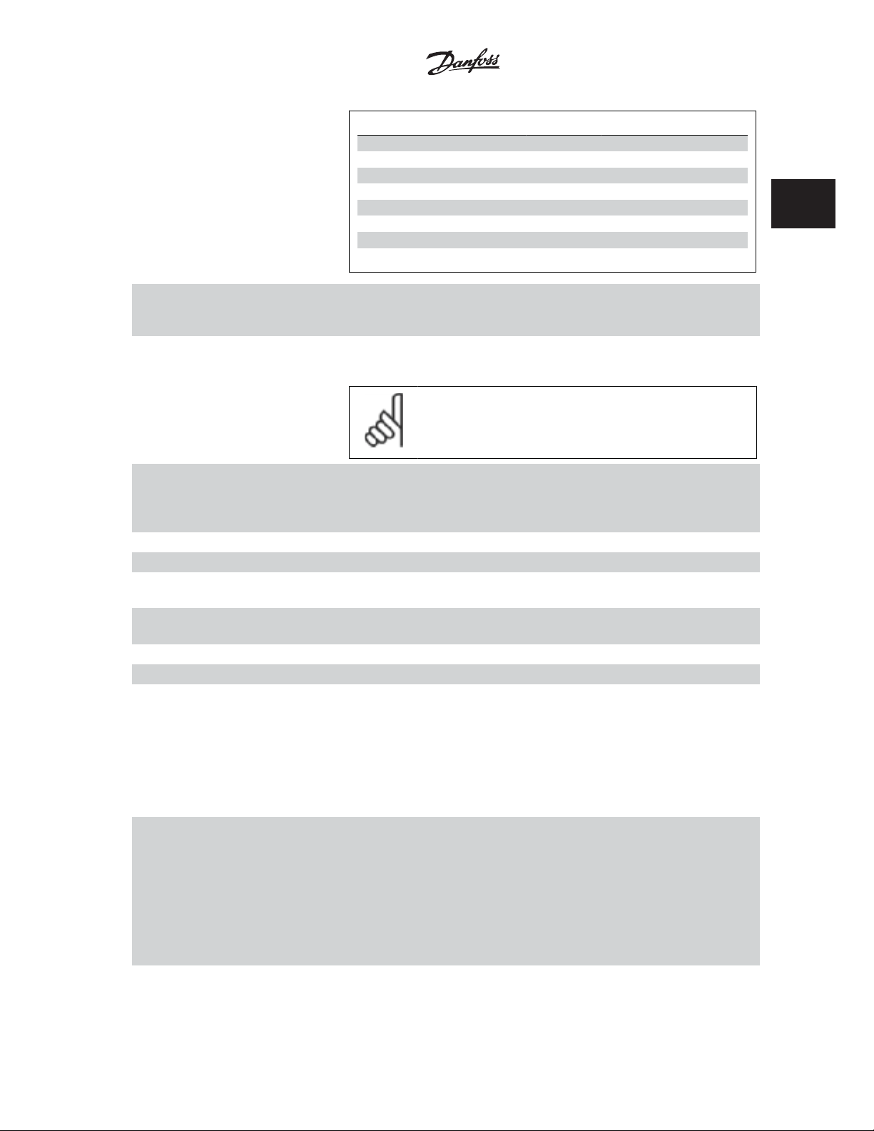
VLTp Automation VT Drive FC322
Programming Guide
Preset ref. bit 210
Preset ref. 0 0 0 0
Preset ref. 1 001
Preset ref. 2 0 1 0
Preset ref. 3 011
Preset ref. 4 1 0 0
Preset ref. 5 101
Preset ref. 6 1 1 0
Preset ref. 7 111
[19] Freeze ref Freezes actual reference. The frozen reference is now the point of enable/condition for Speed up
and Speed down to be used. If Speed up/down is used, the speed change always follows ramp 2
(par. 3-51 and 3-52) in the range 0 - par. 3-03
[20] Freeze output Freezes actual motor frequency (Hz). The frozen motor frequency is now the point of enable/con-
dition for Speed up and Speed down to be used. If Speed up/down is used, the speed change always
follows ramp 2 (par. 3-51 and 3-52) in the range 0 - par. 1-23
NB!
When Freeze output is active, the frequency converter cannot be stopped via a
low ‘start [13]’ signal. Stop the frequency converter via a terminal programmed
for Coasting inverse [2] or Coast and reset, inverse [3].
Maximum Reference
2 Parameter Description
.
Motor Frequency
.
2
[21] Speed up For digital control of the up/down speed is desired (motor potentiometer). Activate this function by
selecting either Freeze reference or Freeze output. When Speed up is activated for less than 400
msec. the resulting reference will be increased by 0.1 %. If Speed up is activated for more than 400
msec. the resulting reference will ramp according to Ramp 1in par. 3-41.
[22] Speed down Same as Speed up [21].
[23] Set-up select bit 0 Selects one of the four set-ups. Set par. 0-10
[24] Set-up select bit 1 Same as Set-up select bit 0 [23].
(Default Digital input 32)
[32] Pulse input Select Pulse input when using a pulse sequence as either reference or feedback. Scaling is done in
par. group 5-5*.
[34] Ramp bit 0 Select which ramp to use. Logic “0” will select ramp 1 while logic “1” will select ramp 2.
[36] Mains failure inverse Activates par. 14-10
[52] Run Permissive The input terminal, for which the Run permissive has been programmed must be logic “1” before a
start command can be accepted. Run permissive has a logic ‘AND’ function related to the terminal
which is programmed for
start running the motor, both conditions must be fulfilled. If Run Permissive is programmed on
multiple terminals, Run permissive needs only be logic ‘1’ on one of the terminals for the function
to be carried out. The digital output signal for Run Request (
[20]) programmed in par. 5-3* Digital outputs, or par. 5-4* Relays, will not be affected by Run
Permissive.
[53] Hand start A signal applied will put the frequency converter into Hand mode as if button
has been pressed and a normal stop command will be overridden. If disconnecting the signal, the
motor will stop. To make any other start commands valid, another digital input must be assign to
Auto Start
and a signal applied to this. The
The
Off
button on the LCP will override
button to make
On
Auto Start
to both
LCP the motor will stop regardless of signals on
, the motor will stop regardless of any normal Start command applied. If signal applied
Hand Start
Mains Failure
Hand Start
and
Auto Start
. Mains failure inverse is active in the Logic “0” situation.
START
[8],
and
, the function will be
Active Set-up
Jog
[14] or
Hand On
Hand Start
Auto Start
active again. If no signal on neither
Hand Start
to Multi Set-up.
Freeze Output
and
Auto On
and
Auto Start
Auto Start
and
[20], which means that in order to
Start
[8],
Jog
[14] or
Freeze output
Hand On
on the LCP
buttons on the LCP has no impact.
. Press either the
Hand On
or
Auto
Hand Start
. If pressing the
Auto Start
.
Off
button on the
nor
MG.20.W1.22 - VLTp is a registered Danfoss trademark
75
Page 78

2 Parameter Description
VLTp Automation VT Drive FC322
Programming Guide
2
[54] Auto start A signal applied will put the frequency converter into Auto mode as if the LCP button
Hand Start
been pressed. See also
[55] DigiPot Increase Uses the input as an INCREASE signal to the Digital Potentiometer function described in parameter
group 3-9*
[56] DigiPot Decrease Uses the input as a DECREASE signal to the Digital Potentiometer function described in parameter
group 3-9*
[57] DigiPot Clear Uses the input to CLEAR the Digital Potentiometer reference described in parameter group 3-9*
[60] Counter A (up) (Terminal 29 or 33 only) Input for increment counting in the SLC counter.
[61] Counter A (down) (Terminal 29 or 33 only) Input for decrement counting in the SLC counter.
[62] Reset Counter A Input for reset of counter A.
[63] Counter B (up) (Terminal 29 and 33 only) Input for increment counting in the SLC counter.
[64] Counter B (down) (Terminal 29 and 33 only) Input for decrement counting in the SLC counter.
[65] Reset Counter B Input for reset of counter B.
[66] Sleep Mode Forces frequency converter into Sleep Mode (see par. 22-4*, Sleep Mode). Reacts on the rising edge
of signal applied!
[78] Reset Preventive Maintenance Word Resets all data in par. 16-96, Preventive Maintenance Word, to 0.
The below setting options are all related to the Cascade Controller. Wiring diagrams and settings for parameter, see group 25-** for more details.
[120] Lead Pump Start Starts/Stops the Lead Pump (controlled by the frequency converter). A start requires that also a
System Start signal has been applied e.g. to one of the digital inputs set for
[121] Lead Pump Alternation Forces alternation of the lead pump in a Cascade Controller.
must be set to either
25-51, can be set to any of the four options.
[130 - 138] Pump1 Interlock - Pump9 Interlock The function will depend on the setting in par. 25-06, Number of Pumps. If set to
Pump1 refers to the pump controlled by relay RELAY1 etc. If set to
pump controlled by the frequency converter only (without any of the build in relays involved) and
Pump2 to the pump controlled by the relay RELAY1. Variable speed pump (lead) cannot be inter-
locked in the basic Cascade Controller.
See below table:
At Command
[53]
[2] or
At Staging or At Command
Lead Pump Alternation
[3].
Alternation Event
Yes
[1], Pump1 refers to the
Start
Auto On
[8]!
, par. 25-50,
No
[0], then
has
, par.
Setting in Par. 5-1* Setting in Par. 25-06
[130] Pump1 Interlock Controlled by RELAY1
[131] Pump2 Interlock Controlled by RELAY2 Controlled by RELAY1
[132] Pump3 Interlock Controlled by RELAY3 Controlled by RELAY2
[133] Pump4 Interlock Controlled by RELAY4 Controlled by RELAY3
[134] Pump5 Interlock Controlled by RELAY5 Controlled by RELAY4
[135] Pump6 Interlock Controlled by RELAY6 Controlled by RELAY5
[136] Pump7 Interlock Controlled by RELAY7 Controlled by RELAY6
[137] Pump8 Interlock Controlled by RELAY8 Controlled by RELAY7
[138] Pump9 Interlock Controlled by RELAY9 Controlled by RELAY8
5-10 Terminal 18 Digital Input
Option: Function:
[0] No operation
[1] Reset
76
MG.20.W1.22 - VLTp is a registered Danfoss trademark
[0] No [1] Yes
(only if not lead pump)
Frequency Converter control-
led
(cannot be interlocked)
Page 79

VLTp Automation VT Drive FC322
Programming Guide
[2] Coast inverse
[3] Coast and reset inv
[5] DC-brake inverse
[6] Stop inverse
[7] External interlock
[8] * Start Same options and functions as par. 5-1*, except for
[9] Latched start
[10] Reversing
[11] Start reversing
[14] Jog
[15] Preset reference on
[16] Preset ref bit 0
[17] Preset ref bit 1
[18] Preset ref bit 2
[19] Freeze reference
[20] Freeze output
[21] Speed up
[22] Speed down
[23] Set-up select bit 0
[24] Set-up select bit 1
[34] Ramp bit 0
[36] Mains failure inverse
[51] Hand/Auto Start
[52] Run permissive
[53] Hand start
[54] Auto start
[55] DigiPot increase
[56] DigiPot decrease
[57] DigiPot clear
[62] Reset Counter A
[65] Reset Counter B
[66] Sleep Mode
[78] Reset Preventive Maintenance Word
[80] PTC Card 1
[120] Lead Pump Start
[121] Lead Pump Alternation
[130] Pump 1 Interlock
[131] Pump 2 Interlock
[132] Pump 3 Interlock
[133] Pump 4 Interlock
[134] Pump 5 Interlock
[135] Pump 6 Interlock
[136] Pump 7 Interlock
Pulse input
2 Parameter Description
.
2
MG.20.W1.22 - VLTp is a registered Danfoss trademark
77
Page 80

2
2 Parameter Description
[137] Pump 8 Interlock
[138] Pump 9 Interlock
5-11 Terminal 19 Digital Input
Option: Function:
[0] * No operation Same options and functions as 5-1*, except for
Option: Function:
5-12 Terminal 27 Digital Input
Option: Function:
Same options and functions as par. 5-1*, except for
[0] * No operation
5-13 Terminal 29 Digital Input
Option: Function:
Same options and functions as par. 5-1*.
[14] * Jog
5-14 Terminal 32 Digital Input
Option: Function:
[0] * No operation Same options and functions as par. 5-1*, except for
Pulse input
VLTp Automation VT Drive FC322
Programming Guide
.
Pulse input
Pulse input
.
.
[1] Reset
[2] Coast inverse
[3] Coast and reset inv
[5] DC-brake inverse
[6] Stop inverse
[7] External interlock
[8] Start
[9] Latched start
[10] Reversing
[11] Start reversing
[14] Jog
[15] Preset reference on
[16] Preset ref bit 0
[17] Preset ref bit 1
[18] Preset ref bit 2
[19] Freeze reference
[20] Freeze output
[21] Speed up
[22] Speed down
[23] Set-up select bit 0
[24] Set-up select bit 1
[34] Ramp bit 0
[36] Mains failure inverse
[51] Hand/Auto Start
78
MG.20.W1.22 - VLTp is a registered Danfoss trademark
Page 81

VLTp Automation VT Drive FC322
Programming Guide
[52] Run permissive
[53] Hand start
[54] Auto start
[55] DigiPot increase
[56] DigiPot decrease
[57] DigiPot clear
[62] Reset Counter A
[65] Reset Counter B
[66] Sleep Mode
[78] Reset Preventive Maintenance Word
[80] PTC Card 1
[120] Lead Pump Start
[121] Lead Pump Alternation
[130] Pump 1 Interlock
[131] Pump 2 Interlock
[132] Pump 3 Interlock
[133] Pump 4 Interlock
[134] Pump 5 Interlock
[135] Pump 6 Interlock
[136] Pump 7 Interlock
[137] Pump 8 Interlock
[138] Pump 9 Interlock
2 Parameter Description
2
5-15 Terminal 33 Digital Input
Option: Function:
Same options and functions as par. 5-1* Digital Inputs.
[0] * No operation
5-16 Terminal X30/2 Digital Input
Option: Function:
This parameter is active when option module MCB 101 is installed in the frequency converter.
It has the same options and functions as par. 5-1* except for
[0] * No operation
5-17 Terminal X30/3 Digital Input
Option: Function:
This parameter is active when option module MCB 101 is installed in the frequency converter.
It has the same options and functions as par. 5-1* except for
[0] * No operation
5-18 Terminal X30/4 Digital Input
Option: Function:
This parameter is active when option module MCB 101 is installed in the frequency converter.
It has the same options and functions as par. 5-1* except for
[0] * No operation
Pulse input
Pulse input
Pulse input
[32].
[32].
[32].
MG.20.W1.22 - VLTp is a registered Danfoss trademark
79
Page 82

VLTp Automation VT Drive FC322
2 Parameter Description
2.7.4 5-3* Digital Outputs
Parameters for configuring the output functions for the output terminals. The 2 solid-state digital outputs are common for terminals 27 and 29. Set the
I/O function for terminal 27 in par. 5-01
Terminal 27 Mode
, and set the I/O function for terminal 29 in par. 5-02
Terminal 29 Mode
Programming Guide
.
2
These parameters cannot be adjusted while the motor is running.
The digital outputs can be programmed with these functions:
[0] No operation
[1] Control ready The control board receives supply voltage.
[2] Drive ready The frequency converter is ready for operation and applies a supply signal on the control board.
[3] Drive ready / remote control The frequency converter is ready for operation and is in Auto On mode.
[4] Stand-by / no warning The frequency converter is ready for operation. No start or stop command is been given (start/
[5] Running Motor is running.
[6] Running / no warning The output speed is higher than the speed set in par. 1-81
[8] Run on reference / no warning Motor runs at reference speed.
[9] Alarm An alarm activates the output. There are no warnings.
[10] Alarm or warning An alarm or a warning activates the output.
[11] At torque limit The torque limit set in par. 4-16 has been exceeded.
[12] Out of current range The motor current is outside the range set in par. 4-18.
[13] Below current, low Motor current is lower than set in par. 4-50.
[14] Above current, high Motor current is higher than set in par. 4-51.
[15] Out of speed range Output speed is outside the range set in par. 4-52 and 4-53.
[16] Below speed, low Output speed is lower than the setting in par. 4-52.
[17] Above speed, high Output speed is higher than the setting in par. 4-53.
[18] Out of feedback range Feedback is outside the range set in par. 4-56 and 4-57.
[19] Below feedback low Feedback is below the limit set in par. 4-56 Warning Feedback Low.
[20] Above feedback high The feedback is above the limit set in par. 4-57
[21] Thermal warning The thermal warning turns on when the temperature exceeds the limit in the motor, the frequency
[25] Reverse
[26] Bus OK Active communication (no time-out) via the serial communication port.
[27] Torque limit and stop Used in performing a coasting stop and in torque limit condition. If the frequency converter has
[28] Brake, no warning The brake is active and there are no warnings.
[29] Brake ready, no fault The brake is ready for operation and there are no faults.
[30] Brake fault (IGBT) The output is Logic ‘1’ when the brake IGBT is short-circuited. Use this function to protect the
[35] External Interlock External Interlock function has been activated via one of the digital inputs.
[40] Out of ref range
[41] Below reference low
Default for all digital outputs and relay outputs
disable). There are no warnings.
Min Speed for Function at Stop [RPM]
The motor is running and there are no warnings.
Warning Feedback High
converter, the brake resistor, or the thermistor.
Reversing. Logic ‘1’ =
activated, no signal, when CCW rotation of the motor.
received a stop signal and is at the torque limit, the signal is Logic ‘0’.
frequency converter if there is a fault on the brake modules. Use the output/relay to cut out the
main voltage from the frequency converter.
relay activated, 24 V DC when CW rotation of the motor. Logic ‘0’ = relay not
.
.
80
MG.20.W1.22 - VLTp is a registered Danfoss trademark
Page 83

VLTp Automation VT Drive FC322
Programming Guide
[42] Above reference high
[45] Bus Ctrl
[46] Bus Ctrl 1 if timeout
[47] Bus Ctrl 0 if timeout
[55] Pulse output
[60] Comparator 0 See par. group 13-1*. If Comparator 0 is evaluated as TRUE, the output will go high. Otherwise, it
will be low.
[61] Comparator 1 See par. group 13-1*. If Comparator 2 is evaluated as TRUE, the output will go high. Otherwise, it
will be low.
[62] Comparator 2 See par. group 13-1*. If Comparator 2 is evaluated as TRUE, the output will go high. Otherwise, it
will be low.
[63] Comparator 3 See par. group 13-1*. If Comparator 3 is evaluated as TRUE, the output will go high. Otherwise, it
will be low.
[64] Comparator 4 See par. group 13-1*. If Comparator 4 is evaluated as TRUE, the output will go high. Otherwise, it
will be low.
[65] Comparator 5 See par. group 13-1*. If Comparator 4 is evaluated as TRUE, the output will go high. Otherwise, it
will be low.
[70] Logic Rule 0 See par. group 13-4*. If Logic Rule 0 is evaluated as TRUE, the output will go high. Otherwise, it
will be low.
[71] Logic Rule 1 See par. group 13-4*. If Logic Rule 1 is evaluated as TRUE, the output will go high. Otherwise, it
will be low.
[72] Logic Rule 2 See par. group 13-4*. If Logic Rule 2 is evaluated as TRUE, the output will go high. Otherwise, it
will be low.
[73] Logic Rule 3 See par. group 13-4*. If Logic Rule 3 is evaluated as TRUE, the output will go high. Otherwise, it
will be low.
[74] Logic Rule 4 See par. group 13-4*. If Logic Rule 4 is evaluated as TRUE, the output will go high. Otherwise, it
will be low.
[75] Logic Rule 5 See par. group 13-4*. If Logic Rule 5 is evaluated as TRUE, the output will go high. Otherwise, it
will be low.
[80] SL Digital Output A See par. 13-52
dig. out. A high
out. A low is executed.
[81] SL Digital Output B See par. 13-52
dig. out. A high
out. A low
[82] SL Digital Output C See par. 13-52
dig. out. A high
out. A low
[83] SL Digital Output D See par. 13-52
dig. out. A
out. A low
[84] SL Digital Output E See par. 13-52
dig. out. A high
out. A low
[85] SL Digital Output F See par. 13-52
dig. out. A high
out. A low
[160] No alarm Output is high when no alarm is present.
SL Control Action
is executed. The input will go low whenever the Smart Logic Action [32] Set dig.
SL Control Action
is executed. The input will go low whenever the Smart Logic Action [33]
is executed.
SL Control Action
is executed. The input will go low whenever the Smart Logic Action [34]
is executed.
SL Control Action
high is executed. The input will go low whenever the Smart Logic Action [35]
is executed.
SL Control Action
is executed. The input will go low whenever the Smart Logic Action [36]
is executed.
SL Control Action
is executed. The input will go low whenever the Smart Logic Action [37]
is executed.
. The input will go high whenever the Smart Logic Action [38]
. The input will go high whenever the Smart Logic Action [39]
. The input will go high whenever the Smart Logic Action [40]
. The input will go high whenever the Smart Logic Action [41]
. The input will go high whenever the Smart Logic Action [42]
. The input will go high whenever the Smart Logic Action [43]
2 Parameter Description
2
Set
Set
Set dig.
Set
Set dig.
Set
Set dig.
Set
Set dig.
Set
Set dig.
MG.20.W1.22 - VLTp is a registered Danfoss trademark
81
Page 84

T
30B
5
.
0
2
VLTp Automation VT Drive FC322
2 Parameter Description
[161] Running reverse The output is high when the frequency converter is running counter clockwise (the logical product
of the status bits ‘running’ AND ‘reverse’).
[165] Local reference active Output is high when par. 3-13
Linked to hand auto
[166] Remote reference active Output is high when par. 3-13
LCP is in [Auto on] mode.
[167] Start command active Output is high when there is an active Start command. (I.e.[Auto On] and a start command via
digital input or bus is active, or [Hand On].
NB!
All inverse Stop/Coast commands must be inactive.
[168] Drive in hand mode Output is high when the frequency converter is in Hand on mode (as indicated by the LED light
above [Hand on].
[169] Drive in auto mode Output is high when the frequency converter is in Hand on mode (as indicated by the LED light
above [Auto on].
[180] Clock Fault The clock function has been reset to default (2000-01-01) because of a power failure.
[181] Preventive Maintenance One or more of the Preventive Maintenance Events programmed in par. 23-10, Preventive Mainte-
nance Item, has passed the time for the specified action in par. 23-11, Maintenance Action.
[190] No-Flow A No-Flow situation or Minimum Speed situation has been detected if enabled in
Detection
. par. 22-21 and/or
[191] Dry Pump A Dry Pump condition has been detected. This function must be enabled in par. 22-26, Dry Pump
Function.
[192] End of Curve Active when an End of Curve condition is present.
[193] Sleep Mode The frequency converter/system has turned into sleep mode. See
[194] Broken Belt A Broken Belt condition has been detected. This function must be enabled in par. 22-60, Broken
Belt Detection.
[195] Bypass Valve Control The bypass valve control (Digital / Relay output in the frequency converter) is used for compressor
systems to unload the compressor during start-up by using a bypass valve. After the start command
is given the bypass valve will be open until the frequency converter reaches
par. 4 -11) . After the limit has been reached the bypass valve will be closed, allowing the compressor
to operate normally. This procedure will not be activated again before a new start is initiated and
the frequency converter speed is zero during the receiving of start signal.
be used in order to delay the motor start. The Bypass valve control principle:
Reference Site
at the same time as the LCP is in Hand on mode.
Reference Site = Remote
No-Flow Detection
= [2] Local or when par. 3-13
[1] or
Linked to hand/auto
, par. 22-22.
Sleep mode
Programming Guide
Reference Site
, par. 22-4*.
Motor speed low limit
Start Delay
= [0]
[0] while the
Minimum Speed
, par. 1-71 can
,
T ime
T ime
ime
1
1
A2
1
Speed
REF
Speed
M in
ON
OFF
ON
OFF
Star t
The below setting options are all related to the Cascade Controller.
Wiring diagrams and settings for parameter, see group 25-** for more details.
82
MG.20.W1.22 - VLTp is a registered Danfoss trademark
St op
Page 85

VLTp Automation VT Drive FC322
Programming Guide
[199] Pipe Filling Active when the Pipe Fill function is operating. See par. 29-0*.
[200] Full Capacity All pumps running and at full speed
[201] Pump1 Running One or more of the pumps controlled by the Cascade Controller are running. The function will also
depend on the setting of in
controlled by relay RELAY1 etc. If set to
frequency converter only (without any of the build in relays involved) and Pump 2 to the pump
controlled by the relay RELAY1. See below table:
[202] Pump2 Running See [201]
[203] Pump3 Running See [201]
Setting in Par. 5-3* Setting in Par. 25-06
[200] Pump 1 Running Controlled by RELAY1 Frequency Converter controlled
[201] Pump 2 Running Controlled by RELAY2 Controlled by RELAY1
[203] Pump 3 Running Controlled by RELAY3 Controlled by RELAY2
5-30 Terminal 27 Digital Output
Option: Function:
Same options and functions as par. 5-3*.
[0] * No operation
Fixed Lead Pump
[0] No [1] Yes
, par. 25-06. If set to No [0] Pump 1 refers to the pump
Yes
[1] Pump 1 refers to the pump controlled by the
2 Parameter Description
2
5-31 Terminal 29 Digital Output
Option: Function:
Same options and functions as par. 5-3*.
[0] * No operation
5-32 Term X30/6 Digi Out (MCB 101)
Option: Function:
[0] * No operation This parameter is active when option module MCB 101 is mounted in the frequency converter.
[1] Control ready The control board receives supply voltage.
[2] Drive ready The frequency converter is ready for operation and applies a supply signal on the control board.
[3] Drive rdy/rem ctrl The frequency converter is ready for operation and is in Auto On mode.
[4] Stand-by / no warning Ready for operation. No start or stop command is been given (start/disable). There are no warnings.
[5] Running Motor is running.
[6] Running / no warning Output speed is higher than the speed set in par. 1-81
motor is running and there are no warnings.
[8] Run on ref/no warn Motor is running within the programmed current and speed ranges set in par. 4-50
Low
to par. 4-53
[9] Alarm An alarm activates the output. There are no warnings.
[10] Alarm or warning An alarm or a warning activates the output.
[11] At torque limit The torque limit set in par. 4-16
Warning Speed High
Torque Limit Motor Mode
. There are no warnings.
Min Speed for Function at Stop [RPM]
Warning Current
or par. 1-17 has been exceeded.
. The
[12] Out of current range The motor current is outside the range set in par. 4-18
[13] Below current, low Motor current is lower than set in par. 4-50
[14] Above current, high Motor current is higher than set in par. 4-51
MG.20.W1.22 - VLTp is a registered Danfoss trademark
Warning Current Low
Warning Current High
Current Limit
.
.
.
83
Page 86

2 Parameter Description
VLTp Automation VT Drive FC322
Programming Guide
2
[15] Out of speed range Output frequency is outside the frequency range set in par. 4-50
Warning Current High
par. 4-51
[16] Below speed, low Output speed is lower than the setting in par. 4-52
[17] Above speed, high Output speed is higher than the setting in par. 4-53
[18] Out of feedb. range Feedback is outside the range set in par. 4-56
.
back High
[19] Below feedback, low Feedback is below the limit set in par. 4-56
[20] Above feedback, high Feedback is above the limit set in par. 4-57
[21] Thermal warning The thermal warning turns on when the temperature exceeds the limit in the motor, the frequency
converter, the brake resistor, or the thermistor.
[25] Reverse
[26] Bus OK Active communication (no time-out) via the serial communication port.
[27] Torque limit & stop Use in performing a coasting stop and in torque limit condition. If the frequency converter has
[28] Brake, no brake war Brake is active and there are no warnings.
[29] Brake ready, no fault Brake is ready for operation and there are no faults.
[30] Brake fault (IGBT) Output is Logic ‘1’ when the brake IGBT is short-circuited. Use this function to protect the frequency
Reversing. Logic ‘1’
the motor is not rotating the output will follow the reference.
received a stop signal and is at the torque limit, the signal is Logic ‘0’.
converter if there is a fault on the brake modules. Use the output/relay to cut out the main voltage
from the frequency converter.
when CW rotation of the motor. Logic ‘0’ when CCW rotation of the motor. If
.
Warning Speed Low
Warning Speed High
Warning Feedback Low
Warning Feedback Low
Warning Feedback High
Warning Current Low
.
.
and par. 4-57
.
.
Warning Feed-
and
[35] External Interlock
[40] Out of ref range
[41] Below reference, low
[42] Above ref, high
[45] Bus ctrl. Controls output via bus. The state of the output is set in par. 5-90
output state is retained in the event of bus time-out.
[46] Bus ctrl, 1 if timeout Controls output via bus. The state of the output is set in par. 5-90
the event of bus time-out the output state is set high (On).
[47] Bus ctrl, 0 if timeout Controls output via bus. The state of the output is set in par. 5-90
the event of bus time-out the output state is set low (Off).
[55] Pulse output
[60] Comparator 0 See par. group LC-1#. If Comparator 0 is evaluated as TRUE, the output will go high. Otherwise, it
will be low.
[61] Comparator 1 See par. group LC-1#. If Comparator 1 is evaluated as TRUE, the output will go high. Otherwise, it
will be low.
[62] Comparator 2 See par. group LC-1#. If Comparator 2 is evaluated as TRUE, the output will go high. Otherwise, it
will be low.
[63] Comparator 3 See par. group LC-1#. If Comparator 3 is evaluated as TRUE, the output will go high. Otherwise, it
will be low.
[64] Comparator 4 See par. group LC-1#. If Comparator 4 is evaluated as TRUE, the output will go high. Otherwise, it
will be low.
Digital & Relay Bus Control
Digital & Relay Bus Control
Digital & Relay Bus Control
. The
. In
. In
84
MG.20.W1.22 - VLTp is a registered Danfoss trademark
Page 87

VLTp Automation VT Drive FC322
Programming Guide
[65] Comparator 5 See par. group LC-1#. If Comparator 5 is evaluated as TRUE, the output will go high. Otherwise, it
will be low.
[70] Logic rule 0 See par. group LC-4#. If Logic Rule 0 is evaluated as TRUE, the output will go high. Otherwise, it
will be low.
2 Parameter Description
[71] Logic rule 1 See par. group LC-4#. If Logic Rule 1 is evaluated as TRUE, the output will go high. Otherwise, it
will be low.
[72] Logic rule 2 See par. group LC-4#. If Logic Rule 2 is evaluated as TRUE, the output will go high. Otherwise, it
will be low.
[73] Logic rule 3 See par. group LC-4#. If Logic Rule 3 is evaluated as TRUE, the output will go high. Otherwise, it
will be low.
[74] Logic rule 4 See par. group LC-4#. If Logic Rule 4 is evaluated as TRUE, the output will go high. Otherwise, it
will be low.
[75] Logic rule 5 See par. group LC-4#. If Logic Rule 5 is evaluated as TRUE, the output will go high. Otherwise, it
will be low.
[80] SL digital output A See par. 13-52
out. A high
is executed.
[81] SL digital output B See par. 13-52
out. A high
executed.
[82] SL digital output C See par. 13-52
out. A high
executed.
[83] SL digital output D See par. 13-52
out. A
executed.
SL Controller Action
is executed. The output will go low whenever the Logic Action [32] Set dig. out. A low
SL Controller Action
is executed. The input will go low whenever the Logic Action [33]
SL Controller Action
is executed. The input will go low whenever theLogic Action [34]
SL Controller Action
high is executed. The input will go low whenever the Logic Action [35]
. The output will go high whenever the Logic Action [38]
. The input will go high whenever the Logic Action [39]
Set dig. out. A low
. The input will go high whenever the Logic Action [40]
Set dig. out. A low
. The input will go high whenever the Logic Action [41]
Set dig. out. A low
Set dig.
Set dig.
Set dig.
Set dig.
2
is
is
is
[84] SL digital output E See par. 13-52
out. A high
executed.
[85] SL digital output F See par. 13-52
out. A high
executed.
[160] No alarm Output is high when no alarm is present.
[161] Running reverse Output is high when the frequency converter is running counter clockwise (the logical product of
the status bits ‘running’ AND ‘reverse’).
[165] Local ref active Output is high when par. 3-13
Linked to hand auto
[166] Remote ref active Output is high when par. 3-13
LCP is in [Auto] mode.
[167] Start command act. Output is high when there is an active Start command (i.e. via digital input bus connection or [Hand]
or [Auto]), and no Stop or Start command is active.
[168] Hand mode Output is high when the frequency converter is in Hand mode (as indicated by the LED light above
[Hand]).
SL Controller Action
is executed. The input will go low whenever the Logic Action [36]
SL Controller Action
is executed. The input will go low whenever the Logic Action [37]
at the same time as the LCP is in Hand mode.
. The input will go high whenever the Logic Action [42]
Set dig. out. A low
. The input will go high whenever the Logic Action [43]
Set dig. out. A low
Reference Site
Reference Site = Remote
= [2] Local or when par. 3-13
[1] or
Linked to hand/auto
Reference Site
Set dig.
Set dig.
= [0]
[0] while the
is
is
MG.20.W1.22 - VLTp is a registered Danfoss trademark
85
Page 88

2
VLTp Automation VT Drive FC322
2 Parameter Description
[169] Auto mode Output is high when the frequency converter is in Hand on mode (as indicated by the LED light
above [Auto]).
[180] Clock Fault
[181] Prev. Maintenance
[188] AHF Capacitor Connect
[189] External Fan Control
[190] No-Flow
[191] Dry Pump
[192] End Of Curve
[193] Sleep Mode
[194] Broken Belt
[195] Bypass Valve Control
[198] Drive Bypass
[199] Pipe Filling
[200] Full capacity
[201] Pump 1 running
[202] Pump 2 running
[203] Pump 3 running
[204] Pump 4 running
[205] Pump 5 running
[206] Pump 6 running
[207] Pump 7 running
[208] Pump 8 running
[209] Pump 9 running
Programming Guide
5-33 Term X30/7 Digi Out (MCB 101)
Option: Function:
[0] * No operation This parameter is active when option module MCB 101 is mounted in the frequency converter.
[1] Control ready The control board receives supply voltage.
[2] Drive ready The frequency converter is ready for operation and applies a supply signal on the control board.
[3] Drive rdy/rem ctrl The frequency converter is ready for operation and is in Auto mode.
[4] Stand-by / no warning Ready for operation. No start or stop command is been given (start/disable). There are no warnings.
[5] Running Motor is running.
[6] Running / no warning Output speed is higher than the speed set in par. 1-81
motor is running and there are no warnings.
[8] Run on ref/no warn Motor runs at reference speed.
[9] Alarm An alarm activates the output. There are no warnings.
[10] Alarm or warning An alarm or a warning activates the output.
[11] At torque limit The torque limit set in par. 4-16
[12] Out of current range The motor current is outside the range set in par. 4-18
[13] Below current, low Motor current is lower than set in par. 4-50
Torque Limit Motor Mode
Warning Current Low
Min Speed for Function at Stop [RPM]
or par. 1-17 has been exceeded.
Current Limit
.
.
. The
86
MG.20.W1.22 - VLTp is a registered Danfoss trademark
Page 89

VLTp Automation VT Drive FC322
Programming Guide
2 Parameter Description
[14] Above current, high Motor current is higher than set in par. 4-51
[15] Out of speed range Output frequency is outside the frequency range set in par. 4-50
Warning Current High
par. 4-51
[16] Below speed, low Output speed is lower than the setting in par. 4-52
[17] Above speed, high Output speed is higher than the setting in par. 4-53
[18] Out of feedb. range Feedback is outside the range set in par. 4-56
.
back High
[19] Below feedback, low Feedback is below the limit set in par. 4-56
[20] Above feedback, high Feedback is above the limit set in par. 4-57
[21] Thermal warning The thermal warning turns on when the temperature exceeds the limit in the motor, the frequency
converter, the brake resistor, or the thermistor.
[25] Reverse
[26] Bus OK Active communication (no time-out) via the serial communication port.
[27] Torque limit & stop Use in performing a coasting stop and in torque limit condition. If the frequency converter has
[28] Brake, no brake war Brake is active and there are no warnings.
[29] Brake ready, no fault Brake is ready for operation and there are no faults.
[30] Brake fault (IGBT) Output is Logic ‘1’ when the brake IGBT is short-circuited. Use this function to protect the frequency
Reversing. Logic ‘1’
the motor is not rotating the output will follow the reference.
received a stop signal and is at the torque limit, the signal is Logic ‘0’.
converter if there is a fault on the brake modules. Use the output/relay to cut out the main voltage
from the frequency converter.
when CW rotation of the motor. Logic ‘0’ when CCW rotation of the motor. If
.
Warning Current High
Warning Speed Low
Warning Speed High
Warning Feedback Low
Warning Feedback Low
Warning Feedback High
.
Warning Current Low
.
.
and par. 4-57
.
.
and
Warning Feed-
2
[35] External Interlock
[40] Out of ref range
[41] Below reference, low
[42] Above ref, high
[45] Bus ctrl. Controls output via bus. The state of the output is set in par. 5-90
output state is retained in the event of bus time-out.
[46] Bus ctrl, 1 if timeout Controls output via bus. The state of the output is set in par. 5-90
the event of bus time-out the output state is set high (On).
[47] Bus ctrl, 0 if timeout Controls output via bus. The state of the output is set in par. 5-90
the event of bus time-out the output state is set low (Off).
[60] Comparator 0 See par. group LC-1#. If Comparator 0 is evaluated as TRUE, the output will go high. Otherwise, it
will be low.
[61] Comparator 1 See par. group LC-1#. If Comparator 1 is evaluated as TRUE, the output will go high. Otherwise, it
will be low.
[62] Comparator 2 See par. group LC-1#. If Comparator 2 is evaluated as TRUE, the output will go high. Otherwise, it
will be low.
[63] Comparator 3 See par. group LC-1#. If Comparator 3 is evaluated as TRUE, the output will go high. Otherwise, it
will be low.
[64] Comparator 4 See par. group LC-1#. If Comparator 4 is evaluated as TRUE, the output will go high. Otherwise, it
will be low.
Digital & Relay Bus Control
Digital & Relay Bus Control
Digital & Relay Bus Control
. The
. In
. In
MG.20.W1.22 - VLTp is a registered Danfoss trademark
87
Page 90

VLTp Automation VT Drive FC322
2 Parameter Description
[65] Comparator 5 See par. group LC-1#. If Comparator 5 is evaluated as TRUE, the output will go high. Otherwise, it
will be low.
[70] Logic rule 0 See par. group LC-4#. If Logic Rule 0 is evaluated as TRUE, the output will go high. Otherwise, it
will be low.
Programming Guide
2
[71] Logic rule 1 See par. group LC-4#. If Logic Rule 1 is evaluated as TRUE, the output will go high. Otherwise, it
will be low.
[72] Logic rule 2 See par. group LC-4#. If Logic Rule 2 is evaluated as TRUE, the output will go high. Otherwise, it
will be low.
[73] Logic rule 3 See par. group LC-4#. If Logic Rule 3 is evaluated as TRUE, the output will go high. Otherwise, it
will be low.
[74] Logic rule 4 See par. group LC-4#. If Logic Rule 4 is evaluated as TRUE, the output will go high. Otherwise, it
will be low.
[75] Logic rule 5 See par. group LC-4#. If Logic Rule 5 is evaluated as TRUE, the output will go high. Otherwise, it
will be low.
[80] SL digital output A See par. 13-52
out. A high
is executed.
[81] SL digital output B See par. 13-52
out. A high
executed.
[82] SL digital output C See par. 13-52
out. A high
executed.
[83] SL digital output D See par. 13-52
out. A
executed.
SL Controller Action
is executed. The output will go low whenever the Logic Action [32] Set dig. out. A low
SL Controller Action
is executed. The input will go low whenever the Logic Action [33]
SL Controller Action
is executed. The input will go low whenever the Logic Action [34]
SL Controller Action
high is executed. The input will go low whenever the Logic Action [35]
. The output will go high whenever the Logic Action [38]
. The input will go high whenever the Logic Action [39]
Set dig. out. A low
. The input will go high whenever the Logic Action [40]
Set dig. out. A low
. The input will go high whenever the Logic Action [41]
Set dig. out. A low
Set dig.
Set dig.
Set dig.
Set dig.
is
is
is
[84] SL digital output E See par. 13-52
out. A high
executed.
[85] SL digital output F See par. 13-52
out. A high
executed.
[160] No alarm Output is high when no alarm is present.
[161] Running reverse Output is high when the frequency converter is running counter clockwise (the logical product of
the status bits ‘running’ AND ‘reverse’).
[165] Local ref active Output is high when par. 3-13
Linked to hand auto
[166] Remote ref active Output is high when par. 3-13
LCP is in [Auto] mode.
[167] Start command act. Output is high when there is an active Start command (i.e. via digital input bus connection or [Hand]
or [Auto]), and no Stop or Start command is active.
[168] Hand mode Output is high when the frequency converter is in Hand mode (as indicated by the LED light above
[Hand]).
SL Controller Action
is executed. The input will go low whenever the Logic Action [36]
SL Controller Action
is executed. The input will go low whenever the Logic Action [37]
at the same time as the LCP is in Hand mode.
. The input will go high whenever the Logic Action [42]
Set dig. out. A low
. The input will go high whenever the Logic Action [43]
Set dig. out. A low
Reference Site
Reference Site = Remote
= [2] Local or when par. 3-13
[1] or
Linked to hand/auto
Reference Site
Set dig.
Set dig.
= [0]
[0] while the
is
is
88
MG.20.W1.22 - VLTp is a registered Danfoss trademark
Page 91

VLTp Automation VT Drive FC322
Programming Guide
[169] Auto mode Output is high when the frequency converter is in Auto mode (as indicated by the LED light above
[Auto]).
[180] Clock Fault
[181] Prev. Maintenance
[188] AHF Capacitor Connect
[189] External Fan Control
[190] No-Flow
[191] Dry Pump
[192] End Of Curve
[193] Sleep Mode
[194] Broken Belt
[195] Bypass Valve Control
[200] Full capacity
[201] Pump 1 running
[202] Pump 2 running
[203] Pump 3 running
[204] Pump 4 running
[205] Pump 5 running
[206] Pump 6 running
[207] Pump 7 running
[208] Pump 8 running
[209] Pump 9 running
2 Parameter Description
2
2.7.5 5-4* Relays
Parameters for configuring the timing and the output functions for the relays.
5-40 Function Relay
Array [8] (Relay 1 [0], Relay 2 [1], Relay 7 [6], Relay 8 [7], Relay 9 [8])
Select options to define the function of the relays.
The selection of each mechanical relay is realized in an array parameter.
[0] * No Operation
[1] Control Ready
[2] Drive Ready
[3] Drive Ready/Remote
[4] Stand-by/No Warning
[5] Running
[6] Running/No Warning
[8] Run on Ref./No Warning
[9] Alarm
[10] Alarm or Warning
[11] At Torque Limit
MG.20.W1.22 - VLTp is a registered Danfoss trademark
89
Page 92

2
2 Parameter Description
[12] Out of Current Range
[13] Below Current, low
[14] Above Current, high
[15] Out of Speed Range
[16] Below Speed, low
[17] Above Speed, high
[18] Out of Feedb. Range
[19] Below Feedback, low
[20] Above Feedback, high
[21] Thermal Warning
[25] Reverse
[26] Bus OK
[27] Torque Limit & Stop
[28] Brake, No Warning
[29] Brake Ready, No Fault
[30] Brake Fault (IGBT)
[35] External Interlock
[36] Control Word Bit 11
[37] Control Word Bit 12
[40] Out of Ref. Range
[41] Below Reference, low
[42] Above Ref. high
[45] Bus ctrl
[46] Bus ctrl, 1 if timeout
[47] Bus ctrl, 0 if timeout
[60] Comparator 0
[61] Comparator 1
[62] Comparator 2
[63] Comparator 3
[64] Comparator 4
[65] Comparator 5
[70] Logic Rule 0
[71] Logic Rule 1
[72] Logic Rule 2
[73] Logic Rule 3
[74] Logic Rule 4
[75] Logic Rule 5
[80] SL Digital Output A
[81] SL Digital Output B
[82] SL Digital Output C
[83] SL Digital Output D
[84] SL Digital Output E
[85] SL Digital Output F
VLTp Automation VT Drive FC322
Programming Guide
90
MG.20.W1.22 - VLTp is a registered Danfoss trademark
Page 93

VLTp Automation VT Drive FC322
Programming Guide
[160] No Alarm
[161] Running Reverse
[165] Local Ref. Active
[166] Remote Ref. Active
[167] Start Cmd. Active
[168] Drive in Hand Mode
[169] Drive in Auto Mode
[180] Clock Fault
[181] Prev. Maintenance
[190] No-Flow
[191] Dry Pump
[192] End of Curve
[193] Sleep Mode
[194] Broken Belt
[195] Bypass Valve Control
[199] Pipe Filling
[211] Cascade Pump1
[212] Cascade Pump2
[213] Cascade Pump3
[223] Alarm, Trip Locked
[224] Bypass Mode Active
2 Parameter Description
2
MG.20.W1.22 - VLTp is a registered Danfoss trademark
91
Page 94

2
VLTp Automation VT Drive FC322
2 Parameter Description
5-41 On Delay, Relay
Array [8](Relay 1 [0], Relay 2 [1], Relay 3 [2], Relay 4 [3], Relay 5 [4], Relay 6 [5], Relay 7 [6], Relay 8 [7], Relay 9 [8])
Range: Function:
0.01 s* [0.01 - 600.00 s] Enter the delay of the relay cut-in time. Select one of available mechanical relays and MCO 105 in
an array function. See par. 5-40
Function Relay
. Relay 3-6 are included in MCB 112 (ATEX).
Programming Guide
5-42 Off Delay, Relay
Array [8] (Relay 1 [0], Relay 2 [1], Relay 3 [2], Relay 4 [3], Relay 5 [4], Relay 6 [5], Relay 7 [6], Relay 8 [7], Relay 9 [8])
Range: Function:
0.01 s* [0.01 - 600.00 s] Enter the delay of the relay cut-out time. Select one of available mechanical relays and MCO 105 in
an array function. See par. 5-40
If the selected Event condition changes before the on- or off delay timer expires, the relay output is unaffected.
Function Relay
.
92
MG.20.W1.22 - VLTp is a registered Danfoss trademark
Page 95

VLTp Automation VT Drive FC322
Programming Guide
2.7.6 5-5* Pulse Input
The pulse input parameters are used to define an appropriate window for the impulse reference area by configuring the scaling and filter settings for the
pulse inputs. Input terminals 29 or 33 act as frequency reference inputs. Set terminal 29 (par. 5-13
(par. 5-15
Terminal 33 Digital Input
) to
Pulse input
[32]. If terminal 29 is used as an input, then set par. 5-02
5-50 Term. 29 Low Frequency
Range: Function:
100 Hz* [0 - 110000 Hz] Enter the low frequency limit corresponding to the low motor shaft speed (i.e. low reference value)
in par. 5-52
Term. 29 Low Ref./Feedb. Value
. Refer to the diagram in this section.
5-51 Term. 29 High Frequency
Range: Function:
100 Hz* [0 - 110000 Hz] Enter the high frequency limit corresponding to the high motor shaft speed (i.e. high reference
value) in par. 5-53
Term. 29 High Ref./Feedb. Value
Terminal 29 Digital Input
Terminal 29 Mode
.
2 Parameter Description
) or terminal 33
to
Input
[0].
2
5-52 Term. 29 Low Ref./Feedb. Value
Range: Function:
0.000* [-999999.999 - 999999.999 ] Enter the low reference value limit for the motor shaft speed [RPM]. This is also the lowest feedback
value, see also par. 5-57
Term. 33 Low Ref./Feedb. Value
.
5-53 Term. 29 High Ref./Feedb. Value
Range: Function:
100.000* [-999999.999 - 999999.999 ] Enter the high reference value [RPM] for the motor shaft speed and the high feedback value, see
also par. 5-58
Term. 33 High Ref./Feedb. Value
.
5-54 Pulse Filter Time Constant #29
Range: Function:
100 ms* [1 - 1000 ms] Enter the pulse filter time constant. The pulse filter dampens oscillations of the feedback signal,
which is an advantage if there is a lot of noise in the system. A high time constant value results in
better dampening but also increases the time delay through the filter.
This parameter cannot be adjusted while the motor is running.
5-55 Term. 33 Low Frequency
Range: Function:
100 Hz* [0 - 110000 Hz] Enter the low frequency corresponding to the low motor shaft speed (i.e. low reference value) in
par. 5-57
Term. 33 Low Ref./Feedb. Value
.
5-56 Term. 33 High Frequency
Range: Function:
100 Hz* [0 - 110000 Hz] Enter the high frequency corresponding to the high motor shaft speed (i.e. high reference value) in
par. 5-58
Term. 33 High Ref./Feedb. Value
.
MG.20.W1.22 - VLTp is a registered Danfoss trademark
93
Page 96

VLTp Automation VT Drive FC322
2 Parameter Description
5-57 Term. 33 Low Ref./Feedb. Value
Range: Function:
0.000* [-999999.999 - 999999.999 ] Enter the low reference value [RPM] for the motor shaft speed. This is also the low feedback value,
see also par. 5-52
Term. 29 Low Ref./Feedb. Value
.
Programming Guide
2
5-58 Term. 33 High Ref./Feedb. Value
Range: Function:
100.000* [-999999.999 - 999999.999 ] Enter the high reference value [RPM] for the motor shaft speed. See also par. 5-53
Ref./Feedb. Value
.
Term. 29 High
5-59 Pulse Filter Time Constant #33
Range: Function:
100 ms* [1 - 1000 ms] Enter the pulse filter time constant. The low-pass filter reduces the influence on and dampens os-
cillations on the feedback signal from the control.
This is an advantage, e.g. if there is a great amount on noise in the system. This parameter cannot
be adjusted while the motor is running.
2.7.7 5-6* Pulse Outputs
Parameters for configuring the scaling and output functions of pulse outputs. The pulse outputs are designated to terminals 27 or 29. Select terminal 27
output in par. 5-01 and terminal 29 output in par. 5-02.
Options for readout output variables:
[0] * No operation
[45] Bus ctrl.
[48] Bus ctrl., timeout
[100] Output frequency
[101] Reference
[102] Feedback
[103] Motor current
94
MG.20.W1.22 - VLTp is a registered Danfoss trademark
Page 97

VLTp Automation VT Drive FC322
Programming Guide
[104] Torque relative to limit
[105] Torque relative to rated
[106] Power
[107] Speed
[108] Torque
[113] Ext. Closed Loop 1
[114] Ext. Closed Loop 2
[115] Ext. Closed Loop 3
5-60 Terminal 27 Pulse Output Variable
Option: Function:
[0] * No operation Same options and functions as par. 5-6*.
Select the operation variable assigned for terminal 27 readouts.
This parameter cannot be adjusted while the motor is running.
[45] Bus ctrl.
[48] Bus ctrl., timeout
[100] Output freq. 0-100
[101] Reference Min-Max
[102] Feedback +-200%
[103] Motor cur. 0-Imax
[104] Torque 0-Tlim
[105] Torque 0-Tnom
[106] Power 0-Pnom
[107] Speed 0-HighLim
[108] Torque +-160%
[109] Out frq 0-Fmax
[113] Ext. Closed Loop 1
[114] Ext. Closed Loop 2
[115] Ext. Closed Loop 3
[116] Cascade Reference
2 Parameter Description
2
5-62 Pulse Output Max Freq #27
Range: Function:
5000 Hz* [0 - 32000 Hz] Set the maximum frequency for terminal 27, corresponding to the output variable selected in
par. 5-60
Terminal 27 Pulse Output Variable
This parameter cannot be adjusted while the motor is running.
MG.20.W1.22 - VLTp is a registered Danfoss trademark
.
95
Page 98

2 Parameter Description
5-63 Terminal 29 Pulse Output Variable
Option: Function:
[0] * No operation Select the variable for viewing on the terminal 29 display.
This parameter cannot be adjusted while the motor is running.
VLTp Automation VT Drive FC322
Programming Guide
2
[45] Bus ctrl.
[48] Bus ctrl., timeout
[100] Output freq. 0-100
[101] Reference Min-Max
[102] Feedback +-200%
[103] Motor cur. 0-Imax
[104] Torque 0-Tlim
[105] Torque 0-Tnom
[106] Power 0-Pnom
[107] Speed 0-HighLim
[108] Torque +-160%
[109] Out frq 0-Fmax
[113] Ext. Closed Loop 1
[114] Ext. Closed Loop 2
[115] Ext. Closed Loop 3
[116] Cascade Reference
5-65 Pulse Output Max Freq #29
Range: Function:
5000 Hz* [0 - 32000 Hz] Set the maximum frequency for terminal 29 corresponding to the output variable set in
Terminal 29 Pulse Output Variable
par. 5-63
This parameter cannot be adjusted while the motor is running.
.
96
MG.20.W1.22 - VLTp is a registered Danfoss trademark
Page 99

VLTp Automation VT Drive FC322
Programming Guide
5-66 Terminal X30/6 Pulse Output Variable
Option: Function:
[0] * No operation Select the variable for read-out on terminal X30/6.
This parameter cannot be adjusted while the motor is running.
This parameter is active when option module MCB 101 is installed in the frequency converter.
[45] Bus ctrl.
[48] Bus ctrl., timeout
[100] Output freq. 0-100
[101] Reference Min-Max
[102] Feedback +-200%
[103] Motor cur. 0-Imax
[104] Torque 0-Tlim
[105] Torque 0-Tnom
[106] Power 0-Pnom
[107] Speed 0-HighLim
[108] Torque +-160%
[109] Out frq 0-Fmax
[113] Ext. Closed Loop 1
[114] Ext. Closed Loop 2
[115] Ext. Closed Loop 3
[116] Cascade Reference
2 Parameter Description
2
5-68 Pulse Output Max Freq #X30/6
Range: Function:
5000 Hz* [0 - 32000 Hz] Select the maximum frequency on terminal X30/6 referring to the output variable in
Terminal X30/6 Pulse Output Variable
par. 5-66
is running.
This parameter is active when option module MCB 101 is mounted in the frequency converter.
. This parameter cannot be adjusted while the motor
2.7.8 5-9*Bus Controlled
This parameter group selects digital and relay outputs via a fieldbus setting.
5-90 Digital & Relay Bus Control
Range: Function:
0* [0 - 2147483647 ] This parameter holds the state of the digital outputs and relays that is controlled by bus.
A logical '1' indicates that the output is high or active.
A logical '0' indicates that the output is low or inactive.
MG.20.W1.22 - VLTp is a registered Danfoss trademark
97
Page 100

2
VLTp Automation VT Drive FC322
2 Parameter Description
Bit 0 CC Digital Output Terminal 27
Bit 1 CC Digital Output Terminal 29
Bit 2 GPIO Digital Output Terminal X 30/6
Bit 3 GPIO Digital Output Terminal X 30/7
Bit 4 CC Relay 1 output terminal
Bit 5 CC Relay 2 output terminal
Bit 6 Option B Relay 1 output terminal
Bit 7 Option B Relay 2 output terminal
Bit 8 Option B Relay 3 output terminal
Bit 9-15 Reserved for future terminals
Bit 16 Option C Relay 1 output terminal
Bit 17 Option C Relay 2 output terminal
Bit 18 Option C Relay 3 output terminal
Bit 19 Option C Relay 4 output terminal
Bit 20 Option C Relay 5 output terminal
Bit 21 Option C Relay 6 output terminal
Bit 22 Option C Relay 7 output terminal
Bit 23 Option C Relay 8 output terminal
Bit 24-31 Reserved for future terminals
5-93 Pulse Out #27 Bus Control
Range: Function:
0.00 %* [0.00 - 100.00 %] Contains the frequency to apply to the digital output terminal 27, when it is configured as [Bus
Controlled].
Programming Guide
5-94 Pulse Out #27 Timeout Preset
Range: Function:
0.00 %* [0.00 - 100.00 %] Contains the frequency to apply to the digital output terminal 27, when it is configured as [Bus
Controlled Timeout] and timeout is detected.
5-95 Pulse Out #29 Bus Control
Range: Function:
0.00 %* [0.00 - 100.00 %] Contains the frequency to apply to the digital output terminal 29, when it is configured as [Bus
Controlled].
5-96 Pulse Out #29 Timeout Preset
Range: Function:
0.00 %* [0.00 - 100.00 %] Contains the frequency to apply to the digital output terminal 29, when it is configured as [Bus
Controlled Timeout] and timeout is detected
5-97 Pulse Out #X30/6 Bus Control
Range: Function:
0.00 %* [0.00 - 100.00 %] Contains the frequency to apply to the digital output terminal 27, when it is configured as [Bus
Controlled.
5-98 Pulse Out #X30/6 Timeout Preset
Range: Function:
0.00 %* [0.00 - 100.00 %] Contains the frequency to apply to the digital output terminal 6, when it is configured as [Bus Con-
trolled Timeout] and time-out is detected.
98
MG.20.W1.22 - VLTp is a registered Danfoss trademark
 Loading...