

Page 1
MAKING MODERN LIVING POSSIBLE
Design Guide
VLT® Automation VT Drive FC 322
Page 2

Page 3

Automation VT Drive FC322 Design Guide Contents
Contents
1 How to Read this Design Guide
Copyright, Limitation of Liability and Revision Rights 5
Symbols 6
Abbreviations 7
Definitions 7
2 Introduction to VLT Automation VT Drive
CE labelling 17
Vibration and shock 19
Control Structures 24
General aspects of EMC 34
Immunity Requirements 38
Galvanic isolation (PELV) 39
PELV - Protective Extra Low Voltage 39
Earth leakage current 40
Control with Brake Function 41
Control with Brake Function 42
Mechanical Brake Control 42
Extreme Running Conditions 42
Safe Stop Operation (Optional) 47
5
15
3 VLT Automation VT Drive Selection
General Specifications 49
Efficiency 65
Special Conditions 72
Options and Accessories 77
General Description 89
High Power Options 95
Installation of Duct Cooling Kit in Rittal Enclosures 95
Outside Installation/ NEMA 3R Kit for Rittal Enclosures 98
Installation on Pedestal 99
Input Plate Option 102
Installation of Mains Shield for Frequency Converters 103
Frame size F Panel Options 104
4 How to Order
Ordering Form 107
Type Code String 108
49
107
MG.20.X1.22 - VLTp is a registered Danfoss trademark
1
Page 4

Contents Automation VT Drive FC322 Design Guide
Ordering Numbers 111
5 How to Install
Mechanical Installation 125
Pre-installation 131
Planning the Installation Site 131
Receiving the Frequency Converter
Transportation and Unpacking 131
Lifting 132
Cooling and Airflow 136
Electrical Installation 140
Connections - Frame sizes D, E and F 156
Power Connections 156
Disconnectors, Circuit Breakers and Contactors 170
Final Set-Up and Test 171
Safe Stop Installation 173
Safe Stop Commissioning Test 174
Additional Connections 176
Installation of Misc. Connections 179
Safety 181
EMC-correct Installation 182
Residual Current Device 186
125
131
6 Application Examples
Potentiometer Reference 188
Automatic Motor Adaptation (AMA) 188
SLC Application Example 189
System Status and Operation 192
Cascade Controller Wiring Diagram
Fixed Variable Speed Pump Wiring Diagram 194
Lead Pump Alternation Wiring Diagram 194
7 RS-485 Installation and Set-up
RS-485 Installation and Set-up 197
FC Protocol Overview 199
Network Configuration 201
FC Protocol Message Framing Structure 201
Examples 209
Modbus RTU Overview 210
187
193
197
2
MG.20.X1.22 - VLTp is a registered Danfoss trademark
Page 5

Automation VT Drive FC322 Design Guide Contents
VLT Automation VT Drive with Modbus RTU 210
Modbus RTU Message Framing Structure 211
How to Access Parameters 216
Examples 217
Danfoss FC Control Profile 222
8 Troubleshooting
231
MG.20.X1.22 - VLTp is a registered Danfoss trademark
3
Page 6

1
1 How to Read this Design Guide Automation VT Drive FC322 Design Guide
4
MG.20.X1.22 - VLTp is a registered Danfoss trademark
Page 7

Automation VT Drive FC322 Design Guide 1 How to Read this Design Guide
1 How to Read this Design Guide
1
1.1.1 Copyright, Limitation of Liability and Revision Rights
This publication contains information proprietary to Danfoss. By accepting and using this manual the user agrees that the information contained herein
will be used solely for operating equipment from Danfoss or equipment from other vendors provided that such equipment is intended for communication
with Danfoss equipment over a serial communication link. This publication is protected under the Copyright laws of Denmark and most other countries.
Danfoss does not warrant that a software program produced according to the guidelines provided in this manual will function properly in every physical,
hardware or software environment.
Although Danfoss has tested and reviewed the documentation within this manual, Danfoss makes no warranty or representation, neither expressed nor
implied, with respect to this documentation, including its quality, performance, or fitness for a particular purpose.
In no event shall Danfoss be liable for direct, indirect, special, incidental, or consequential damages arising out of the use, or the inability to use information
contained in this manual, even if advised of the possibility of such damages. In particular, Danfoss is not responsible for any costs, including but not
limited to those incurred as a result of lost profits or revenue, loss or damage of equipment, loss of computer programs, loss of data, the costs to substitute
these, or any claims by third parties.
Danfoss reserves the right to revise this publication at any time and to make changes to its contents without prior notice or any obligation to notify former
or present users of such revisions or changes.
1.1.2
Available Literature for VLT
®
Automation VT Drive FC322
®
-
-
-
-
-
-
- Output Filters Design Guide MG.90.Nx.yy
-
- Application Note MN20A102: Submersible Pump Application
- Application Note MN20B102: Master/Follower Operation Application
- Application Note MN20F102: Drive Closed Loop and Sleep Mode
- Instruction MI.38.Bx.yy: Installation Instruction for Mounting Brackets Enclosure type A5, B1, B2, C1 and C2 IP21, IP55 or IP66
- Instruction MI.90.Lx.yy: Analog I/O Option MCB109
- Instruction MI.33.Hx.yy: Panel through mount kit
x = Revision number
yy = Language code
Danfoss technical literature is also available online at
www.danfoss.com/BusinessAreas/DrivesSolutions/Documentations/Technical+Documentation.htm
Automation VT Drive FC322 Instruction Manual MG.20.Ux.yy provide the neccessary information for getting the drive up and running.
VLT
®
Automation VT Drive FC322 High Power Instruction Manual MG.20.Vx.yy provide the neccessary information for getting the HP drive up
VLT
and running.
®
VLT
Automation VT Drive FC322 Design Guide MG.20.Xx.yy entails all technical information about the drive and customer design and appli-
cations.
®
VLT
Automation VT Drive FC322 Programming Guide MN.20.Wx.yy provides information on how to programme and includes complete pa-
rameter descriptions.
®
VLT
Automation VT Drive FC322 Profibus MG.33.Cx.yy
®
Automation VT Drive FC322 DeviceNet MG.33.Dx.yy
VLT
®
VLT
Automation VT Drive FC322 Cascade Controller MI.38.Cx.yy
.
MG.20.X1.22 - VLTp is a registered Danfoss trademark
5
Page 8
1
1 How to Read this Design Guide Automation VT Drive FC322 Design Guide
1.1.3 Symbols
Symbols used in this guide.
NB!
Indicates something to be noted by the reader.
Indicates a general warning.
Indicates a high-voltage warning.
Indicates default setting
6
MG.20.X1.22 - VLTp is a registered Danfoss trademark
Page 9
Automation VT Drive FC322 Design Guide 1 How to Read this Design Guide
1.1.4 Abbreviations
Alternating current AC
American wire gauge AWG
Ampere/AMP A
Automatic Motor Adaptation AMA
Current limit I
Degrees Celsius °C
Direct current DC
Drive Dependent D-TYPE
Electro Magnetic Compatibility EMC
Electronic Thermal Relay ETR
Drive FC
Gram g
Hertz Hz
Kilohertz kHz
Local Control Panel LCP
Meter m
Millihenry Inductance mH
Milliampere mA
Millisecond ms
Minute min
Motion Control Tool MCT
Nanofarad nF
Newton Meters Nm
Nominal motor current I
Nominal motor frequency f
Nominal motor power P
Nominal motor voltage U
Parameter par.
Protective Extra Low Voltage PELV
Printed Circuit Board PCB
Rated Inverter Output Current I
Revolutions Per Minute RPM
Regenerative terminals Regen
Second s
Synchronous Motor Speed n
Torque limit T
Volts V
I
VLT,MAX
I
VLT,N
LIM
M,N
M,N
M,N
M,N
INV
s
LIM
The maximum output current
The rated output current supplied by the frequency converter
1
1.1.5 Definitions
Drive:
I
VLT,MAX
The maximum output current.
I
VLT,N
The rated output current supplied by the frequency converter.
U
VLT, MAX
The maximum output voltage.
MG.20.X1.22 - VLTp is a registered Danfoss trademark
7
Page 10
1
1 How to Read this Design Guide Automation VT Drive FC322 Design Guide
Input:
Control command
You can start and stop the connected motor by means of
LCP and the digital inputs.
Functions are divided into two groups.
Functions in group 1 have higher priority than functions in
group 2.
Motor:
f
JOG
The motor frequency when the jog function is activated (via digital terminals).
f
M
The motor frequency.
f
MAX
The maximum motor frequency.
f
MIN
The minimum motor frequency.
f
M,N
The rated motor frequency (nameplate data).
I
M
The motor current.
I
M,N
The rated motor current (nameplate data).
n
M,N
The rated motor speed (nameplate data).
P
M,N
The rated motor power (nameplate data).
T
M,N
The rated torque (motor).
U
M
The instantaneous motor voltage.
U
M,N
The rated motor voltage (nameplate data).
Group 1 Reset, Coasting stop, Reset and Coasting stop, Quick-
stop, DC braking, Stop and the "Off" key.
Group 2 Start, Pulse start, Reversing, Start reversing, Jog and
Freeze output
8
MG.20.X1.22 - VLTp is a registered Danfoss trademark
Page 11

Automation VT Drive FC322 Design Guide 1 How to Read this Design Guide
VLT
The efficiency of the frequency converter is defined as the ratio between the power output and the power input.
Start-disable command
A stop command belonging to the group 1 control commands - see this group.
Stop command
See Control commands.
References:
Analog Reference
A signal transmitted to the analog inputs 53 or 54, can be voltage or current.
Bus Reference
A signal transmitted to the serial communication port (FC port).
Preset Reference
A defined preset reference to be set from -100% to +100% of the reference range. Selection of eight preset references via the digital terminals.
Pulse Reference
A pulse frequency signal transmitted to the digital inputs (terminal 29 or 33).
Ref
MAX
Determines the relationship between the reference input at 100% full scale value (typically 10 V, 20mA) and the resulting reference. The maximum
reference value set in par. 3-03.
1
Ref
MIN
Determines the relationship between the reference input at 0% value (typically 0V, 0mA, 4mA) and the resulting reference. The minimum reference value
set in par. 3-02.
Miscellaneous:
Analog Inputs
The analog inputs are used for controlling various functions of the frequency converter.
There are two types of analog inputs:
Current input, 0-20 mA and 4-20 mA
Voltage input, 0-10 V DC.
Analog Outputs
The analog outputs can supply a signal of 0-20 mA, 4-20 mA, or a digital signal.
Automatic Motor Adaptation, AMA
AMA algorithm determines the electrical parameters for the connected motor at standstill.
Brake Resistor
The brake resistor is a module capable of absorbing the brake power generated in regenerative braking. This regenerative braking power increases the
intermediate circuit voltage and a brake chopper ensures that the power is transmitted to the brake resistor.
CT Characteristics
Constant torque characteristics used for positive displacement pumps and blowers.
MG.20.X1.22 - VLTp is a registered Danfoss trademark
9
Page 12

1
1 How to Read this Design Guide Automation VT Drive FC322 Design Guide
Digital Inputs
The digital inputs can be used for controlling various functions of the frequency converter.
10
MG.20.X1.22 - VLTp is a registered Danfoss trademark
Page 13

Automation VT Drive FC322 Design Guide 1 How to Read this Design Guide
Digital Outputs
The drive features two Solid State outputs that can supply a 24 V DC (max. 40 mA) signal.
DSP
Digital Signal Processor.
Relay Outputs:
The frequency converter drive features two programmable Relay Outputs.
ETR
Electronic Thermal Relay is a thermal load calculation based on present load and time. Its purpose is to estimate the motor temperature.
GLCP:
Graphical Local Control Panel (LCP102)
Initialising
If initialising is carried out (par. 14-22), the programmable parameters of the frequency converter return to their default set tings.
Intermittent Duty Cycle
An intermittent duty rating refers to a sequence of duty cycles. Each cycle consists of an on-load and an off-load period. The operation can be either
periodic duty or none-periodic duty.
LCP
The Local Control Panel (LCP) makes up a complete interface for control and programming of the frequency converter. The control panel is detachable
and can be installed up to 3 metres from the frequency converter, i.e. in a front panel by means of the installation kit option.
The Local Control Panel is available in two versions:
- Numerical LCP101 (NLCP)
- Graphical LCP102 (GLCP)
lsb
Least significant bit.
1
MCM
Short for Mille Circular Mil, an American measuring unit for cable cross-section. 1 MCM ิ 0.5067 mm
msb
Most significant bit.
NLCP
Numerical Local Control Panel LCP101
On-line/Off-line Parameters
Changes to on-line parameters are activated immediately after the data value is changed. Changes to off-line parameters are not activated until you enter
[OK] on the LCP.
PID Controller
The PID controller maintains the desired speed, pressure, temperature, etc. by adjusting the output frequency to match the varying load.
RCD
Residual Current Device.
MG.20.X1.22 - VLTp is a registered Danfoss trademark
2
.
11
Page 14

1
1 How to Read this Design Guide Automation VT Drive FC322 Design Guide
Set-up
You can save parameter settings in four Set-ups. Change between the four parameter Set-ups and edit one Set-up, while another Set-up is active.
12
MG.20.X1.22 - VLTp is a registered Danfoss trademark
Page 15

Automation VT Drive FC322 Design Guide 1 How to Read this Design Guide
SFAVM
Switching pattern called
S tator F lux oriented A synchronous V ector M odulation (par. 14-00).
Slip Compensation
The frequency converter compensates for the motor slip by giving the frequency a supplement that follows the measured motor load keeping the motor
speed almost constant..
Smart Logic Control (SLC)
The SLC is a sequence of user defined actions executed when the associated user defined events are evaluated as true by the SLC.
Thermistor:
A temperature-dependent resistor placed where the temperature is to be monitored (frequency converter or motor).
Trip
A state entered in fault situations, e.g. if the frequency converter is subject to an over-temperature or when the frequency converter is protecting the
motor, process or mechanism. Restart is prevented until the cause of the fault has disappeared and the trip state is cancelled by activating reset or, in
some cases, by being programmed to reset automatically. Trip may not be used for personal safety.
Trip Locked
A state entered in fault situations when the frequency converter is protecting itself and requiring physical intervention, e.g. if the frequency converter is
subject to a short circuit on the output. A locked trip can only be cancelled by cutting off mains, removing the cause of the fault, and reconnecting the
frequency converter. Restart is prevented until the trip state is cancelled by activating reset or, in some cases, by being programmed to reset automatically.
Trip locked may not be used for personal safety.
VT Characteristics
Variable torque characteristics used for pumps and fans.
plus
VVC
If compared with standard voltage/frequency ratio control, Voltage Vector Control (VVC
reference is changed and in relation to the load torque.
plus
) improves the dynamics and the stability, both when the speed
1
60° AVM
Switching pattern called 60°
A synchronous V ector M odulation (par. 14-00).
1.1.6 Power Factor
The power factor is the relation between I1 and I
The power factor for 3-phase control:
The power factor indicates to which extent the frequency converter im-
poses a load on the mains supply.
The lower the power factor, the higher the I
formance.
In addition, a high power factor indicates that the different harmonic currents are low.
The frequency converters' built-in DC coils produce a high power factor, which minimizes the imposed load on the mains supply.
.
RMS
for the same kW per-
RMS
MG.20.X1.22 - VLTp is a registered Danfoss trademark
Power factor
I
cos
×
1
=
I
RMS
I
RMS
2
=
I
1
+
1
=
2
I
5
3 × U ×
3 × U ×
I
1
=
I
RMS
2
+
+ . . +
I
7
I
1 ×
I
since cos
COS
RMS
1=1
2
I
n
13
Page 16

2
2 Introduction to VLT Automation VT Drive Automation VT Drive FC322 Design Guide
14
MG.20.X1.22 - VLTp is a registered Danfoss trademark
Page 17
Automation VT Drive FC322 Design Guide 2 Introduction to VLT Automation VT Drive
2 Introduction to VLT Automation VT Drive
2.1 Safety
2.1.1 Safety Note
The voltage of the frequency converter is dangerous whenever connected to mains. Incorrect installation of the motor, frequency
converter or fieldbus may cause damage to the equipment, serious personal injury or death. Consequently, the instructions in this
manual, as well as national and local rules and safety regulations, must be complied with.
Safety Regulations
1. The frequency converter must be disconnected from mains if repair work is to be carried out. Check that the mains supply has been disconnected and
that the necessary time has passed before removing motor and mains plugs.
2. The [STOP/RESET] key on the control panel of the frequency converter does not disconnect the equipment from mains and is thu s not to be used as
a safety switch.
3. Correct protective earthing of the equipment must be established, the user must be protected against supply voltage, and the motor must be protected
against overload in accordance with applicable national and local regulations.
4. The earth leakage currents are higher than 3.5 mA.
5. Protection against motor overload is set by par. 1-90
value) or data value [ETR warning]. Note: The function is initialised at 1.16 x rated motor current and rated motor frequency. For the North American
market: The ETR functions provide class 20 motor overload protection in accordance with NEC.
6. Do not remove the plugs for the motor and mains supply while the frequency converter is connected to mains. Check that the mains supply has been
disconnected and that the necessary time has passed before removing motor and mains plugs.
7. Please note that the frequency converter has more voltage inputs than L1, L2 and L3, when load sharing (linking of DC intermediate circuit) and external
24 V DC have been installed. Check that all voltage inputs have been disconnected and that the necessary time has passed before commencing repair
work.
Installation at High Altitudes
Motor Thermal Protection
. If this function is desired, set par. 1-90 to data value [ETR trip] (default
2
By altitudes above 2 km, please contact Danfoss regarding PELV.
Warning against Unintended Start
1. The motor can be brought to a stop by means of digital commands, bus commands, references or a local stop, while the frequency converter is
connected to mains. If personal safety considerations make it necessary to ensure that no unintended start occurs, these stop functions are not sufficient.
2. While parameters are being changed, the motor may start. Consequently, the stop key [STOP/RESET] must always be activated; following which data
can be modified. 3. A motor that has been stopped may start if faults occur in the electronics of the frequency converter, or if a temporary overload or
a fault in the supply mains or the motor connection ceases.
Warning:
Touching the electrical parts may be fatal - even after the equipment has been disconnected from mains.
Also make sure that other voltage inputs have been disconnected, such as external 24 V DC, load sharing (linkage of DC intermediate circuit), as well as
the motor connection for kinetic back up.
VLTp Automation VT Drive FC322 Instruction Manual MG.20.UX.YY
Refer to
MG.20.X1.22 - VLTp is a registered Danfoss trademark
for further safety guidelines.
15
Page 18
2
2 Introduction to VLT Automation VT Drive Automation VT Drive FC322 Design Guide
2.1.2 Caution
The frequency converter DC link capacitors remain charged after power has been disconnected. To avoid an electrical shock hazard,
disconnect the frequency converter from the mains before carrying out maintenance. Wait at least as follows before doing service on
the frequency converter:
Voltage (V) Min. Waiting Time (Minutes)
4 15 20 30 40
200 - 240 0.25 - 3.7 kW 5.5 - 45 kW
380 - 480 0.37 - 7.5 kW 11 - 90 kW 110 - 250 kW 315 - 1000 kW
525-600 0.75 kW - 7.5 kW 11 - 90 kW 315 - 1200 kW
525-690 11 - 90 kW 45 - 400 kW 450 - 1200 kW
Be aware that there may be high voltage on the DC link even when the LEDs are turned off.
2.1.3 Disposal Instruction
Equipment containing electrical components may not be disposed of together with domestic
waste.
It must be separately collected with electrical and electronic waste according to local and cur-
rently valid legislation.
2.2 Software Version
2.2.1 Software Version and Approvals
VLT Automation VT Drive FC322
Software version: 1.7x
This manual can be used with all VLT Automation VT Drive FC322 frequency converters with software version 1.7x.
The software version number can be found in parameter 15-43.
16
MG.20.X1.22 - VLTp is a registered Danfoss trademark
Page 19

Automation VT Drive FC322 Design Guide 2 Introduction to VLT Automation VT Drive
2.3 CE labelling
2.3.1 CE Conformity and Labelling
What is CE Conformity and Labelling?
The purpose of CE labelling is to avoid technical trade obstacles within EFTA and the EU. The EU has introduced the CE label as a simple way of showing
whether a product complies with the relevant EU directives. The CE label says nothing about the specifications or quality of the product. Frequency
converters are regulated by three EU directives:
The machinery directive (98/37/EEC)
All machines with critical moving parts are covered by the machinery directive of January 1, 1995. Since a frequency converter is largely electrical, it does
not fall under the machinery directive. However, if a frequency converter is supplied for use in a machine, we provide information on safety aspects
relating to the frequency converter. We do this by means of a manufacturer's declaration.
The low-voltage directive (73/23/EEC)
Frequency converters must be CE labelled in accordance with the low-voltage directive of January 1, 1997. The directive applies to all electrical equipment
and appliances used in the 50 - 1000 V AC and the 75 - 1500 V DC voltage ranges. Danfoss CE-labels in accordance with the directive and issues a
declaration of conformity upon request.
The EMC directive (89/336/EEC)
EMC is short for electromagnetic compatibility. The presence of electromagnetic compatibility means that the mutual interference between different
components/appliances does not affect the way the appliances work.
The EMC directive came into effect January 1, 1996. Danfoss CE-labels in accordance with the directive and issues a declaration of conformity upon
request. To carry out EMC-correct installation, see the instructions in this Design Guide. In addition, we specify which standards our products comply
with. We offer the filters presented in the specifications and provide other types of assistance to ensure the optimum EMC result.
The frequency converter is most often used by professionals of the trade as a complex component forming part of a larger appliance, system or installation.
It must be noted that the responsibility for the final EMC properties of the appliance, system or installation rests with the installer.
2.3.2 What Is Covered
2
The EU "
Guidelines on the Application of Council Directive 89/336/EEC
coverage and CE labelling.
1. The frequency converter is sold directly to the end-consumer. The frequency converter is for example sold to a DIY market. The end-consumer
is a layman. He installs the frequency converter himself for use with a hobby machine, a kitchen appliance, etc. For such applications, the
frequency converter must be CE labelled in accordance with the EMC directive.
2. The frequency converter is sold for installation in a plant. The plant is built up by professionals of the trade. It could be a production plant or a
heating/ventilation plant designed and installed by professionals of the trade. Neither the frequency converter nor the finished plant has to be
CE labelled under the EMC directive. However, the unit must comply with the basic EMC requirements of the directive. This is ensured by using
components, appliances, and systems that are CE labelled under the EMC directive.
3. The frequency converter is sold as part of a complete system. The system is being marketed as complete and could e.g. be an air-conditioning
system. The complete system must be CE labelled in accordance with the EMC directive. The manufacturer can ensure CE labelling under the
EMC directive either by using CE labelled components or by testing the EMC of the system. If he chooses to use only CE labelled components,
he does not have to test the entire system.
" outline three typical situations of using a frequency converter. See below for EMC
MG.20.X1.22 - VLTp is a registered Danfoss trademark
17
Page 20

2
2 Introduction to VLT Automation VT Drive Automation VT Drive FC322 Design Guide
2.3.3 Danfoss Frequency Converter and CE Labelling
CE labelling is a positive feature when used for its original purpose, i.e. to facilitate trade within the EU and EFTA.
However, CE labelling may cover many different specifications. Thus, you have to check what a given CE label specifically covers.
The covered specifications can be very different and a CE label may therefore give the installer a false feeling of security when using a frequency converter
as a component in a system or an appliance.
Danfoss CE labels the frequency converters in accordance with the low-voltage directive. This means that if the frequency converter is installed correctly,
we guarantee compliance with the low-voltage directive. Danfoss issues a declaration of conformity that confirms our CE labelling in accordance with the
low-voltage directive.
The CE label also applies to the EMC directive provided that the instructions for EMC-correct installation and filtering are followed. On this basis, a
declaration of conformity in accordance with the EMC directive is issued.
The Design Guide offers detailed instructions for installation to ensure EMC-correct installation. Furthermore, Danfoss specifies which our different prod-
ucts comply with.
Danfoss gladly provides other types of assistance that can help you obtain the best EMC result.
2.3.4 Compliance with EMC Directive 89/336/EEC
As mentioned, the frequency converter is mostly used by professionals of the trade as a complex component forming part of a larger appliance, system,
or installation. It must be noted that the responsibility for the final EMC properties of the appliance, system or installation rests with the installer. As an
aid to the installer, Danfoss has prepared EMC installation guidelines for the Power Drive system. The standards and test levels stated for Power Drive
systems are complied with, provided that the EMC-correct instructions for installation are followed, see the section
The frequency converter has been designed to meet the IEC/EN 60068-2-3 standard, EN 50178 pkt. 9.4.2.2 at 50°C.
A frequency converter contains a large number of mechanical and electronic components. All are to some extent vulnerable to environmental effects.
The frequency converter should not be installed in environments with airborne liquids, particles, or gases capable of affecting and
damaging the electronic components. Failure to take the necessary protective measures increases the risk of stoppages, thus reducing
the life of the frequency converter.
Liquids can be carried through the air and condense in the frequency converter and may cause corrosion of components and metal parts. Steam, oil, and
salt water may cause corrosion of components and metal parts. In such environments, use equipment with enclosure rating IP 54/55. As an extra
protection, coated printed circuit boards can be ordered as an option.
Particles such as dust may cause mechanical, electrical, or thermal failure in the frequency converter. A typical indicator of excessive levels of
Airborne
airborne particles is dust particles around the frequency converter fan. In very dusty environments, use equipment with enclosure rating IP 54/55 or a
cabinet for IP 00/IP 20/TYPE 1 equipment.
In environments with high temperatures and humidity,
on the frequency converter components.
corrosive gases such as sulphur, nitrogen, and chlorine compounds will cause chemical processes
EMC Immunity
.
18
MG.20.X1.22 - VLTp is a registered Danfoss trademark
Page 21
Automation VT Drive FC322 Design Guide 2 Introduction to VLT Automation VT Drive
Such chemical reactions will rapidly affect and damage the electronic components. In such environments, mount the equipment in a cabinet with fresh
air ventilation, keeping aggressive gases away from the frequency converter.
An extra protection in such areas is a coating of the printed circuit boards, which can be ordered as an option.
NB!
Mounting frequency converters in aggressive environments increases the risk of stoppages and considerably reduces the life of the
converter.
Before installing the frequency converter, check the ambient air for liquids, particles, and gases. This is done by observing existing installations in this
environment. Typical indicators of harmful airborne liquids are water or oil on metal parts, or corrosion of metal parts.
Excessive dust particle levels are often found on installation cabinets and existing electrical installations. One indicator of aggressive airborne gases is
blackening of copper rails and cable ends on existing installations.
NB!
D and E enclosures have a stainless steel back-channel option to provide additional protection in aggressive environments. Proper ventilation is still
required for the internal components of the drive. Contact Danfoss for additional information.
2
2.4 Vibration and shock
The frequency converter has been tested according to the procedure based on the shown standards:
The frequency converter complies with requirements that exist for units mounted on the walls and floors of production premises, as well as in panels
bolted to walls or floors.
IEC/EN 60068-2-6: Vibration (sinusoidal) - 1970
IEC/EN 60068-2-64: Vibration, broad-band random
2.5 Advantages
2.7.1 Why use a Frequency Converter for Controlling Fans and Pumps?
A frequency converter takes advantage of the fact that centrifugal fans and pumps follow the laws of proportionality for such fans and pumps. For further
information see the text
The Laws of Proportionality
2.7.2 The Clear Advantage - Energy Savings
The very clear advantage of using a frequency converter for controlling the speed of fans or pumps lies in the electricity savings.
When comparing with alternative control systems and technologies, a frequency converter is the optimum energy control system for controlling fan and
pump systems.
.
MG.20.X1.22 - VLTp is a registered Danfoss trademark
19
Page 22
2
2 Introduction to VLT Automation VT Drive Automation VT Drive FC322 Design Guide
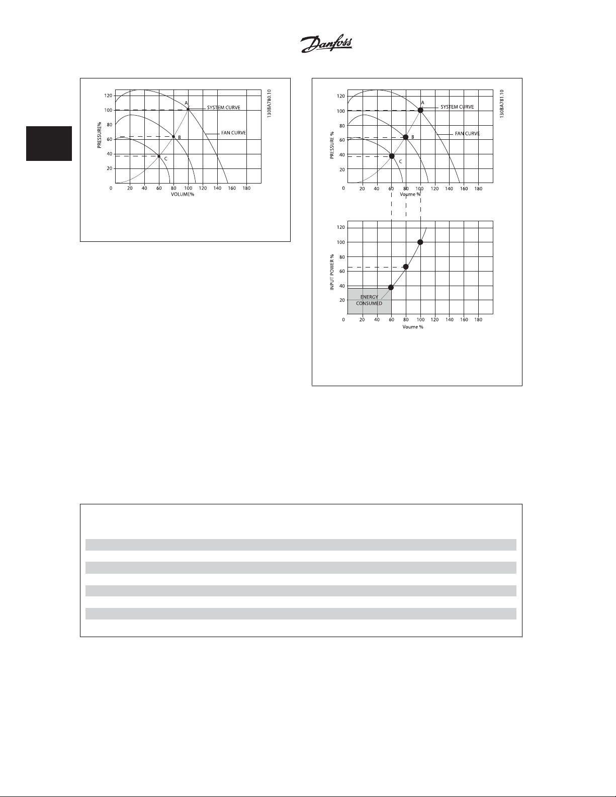
Illustration 2.1: The graph is showing fan curves (A, B and
C) for reduced fan volumes.
Illustration 2.2: When using a frequency converter to reduce
fan capacity to 60% - more than 50% energy savings may
be obtained in typical applications.
2.7.3 Example of Energy Savings
As can be seen from the figure (the laws of proportional ity), the flow is controlled by changing t he RPM. By reducing the speed only 20% from the rated
speed, the flow is also reduced by 20%. This is because the flow is directly proportional to the RPM. The consumption of electricity, however, is reduced
by 50%.
If the system in question only needs to be able to supply a flow that corresponds to 100% a few days in a year, while the average is below 80% of the
rated flow for the remainder of the year, the amount of energy saved is even more than 50%.
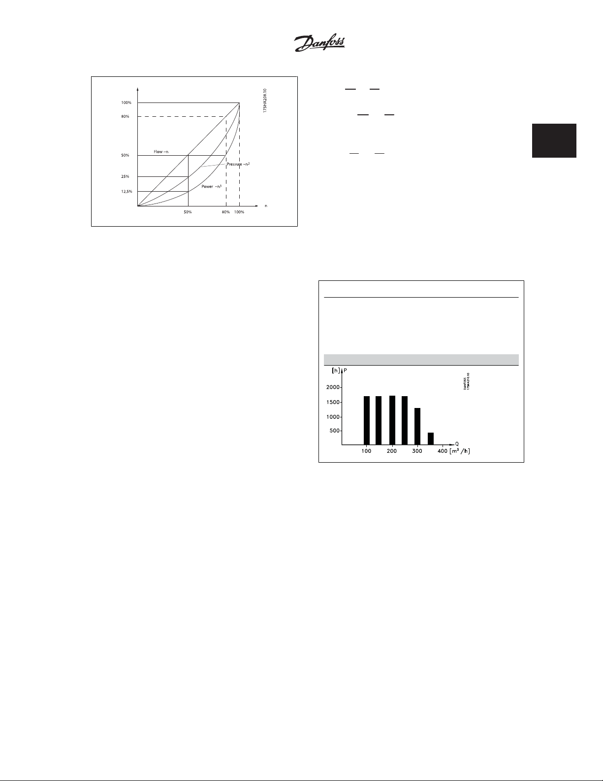
The laws of proportionality
The figure below describes the dependence of flow, pressure and power consumption on RPM.
Q = Flow P = Power
Q1 = Rated flow P1 = Rated power
Q
= Reduced flow P2 = Reduced power
2
H = Pressure n = Speed regulation
H1 = Rated pressure n1 = Rated speed
H
= Reduced pressure n2 = Reduced speed
2
20
MG.20.X1.22 - VLTp is a registered Danfoss trademark
Page 23
Automation VT Drive FC322 Design Guide 2 Introduction to VLT Automation VT Drive
Q
n
1
Flow
:
Pressure
1
=
Q
n
2
2
H
n
=
2
1
(
)
n
2
1
:
H
2
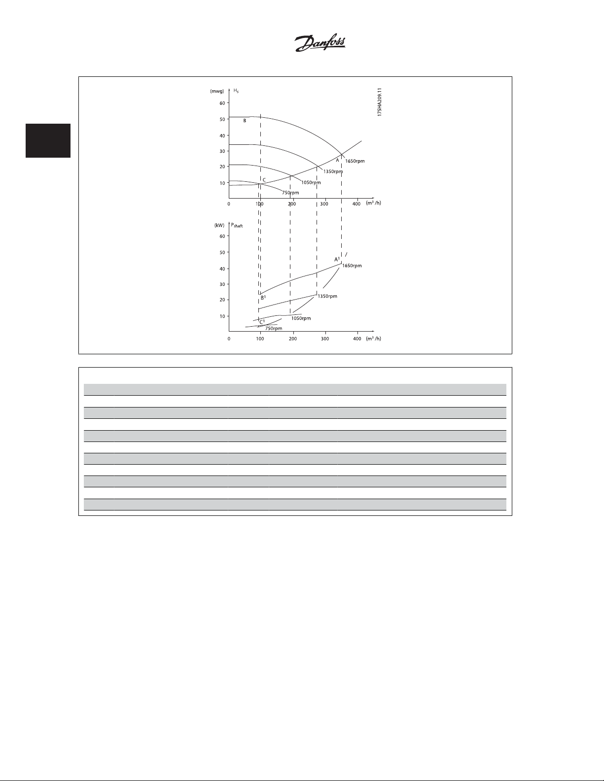
2.7.4 Example with Varying Flow over 1 Year
The example below is calculated on the basis of pump characteristics ob-
tained from a pump datasheet.
The result obtained shows energy savings in excess of 50% at the given
flow distribution over a year. The pay back period depends on the price
per kwh and price of frequency converter. In this example it is less than
a year when compared with valves and constant speed.
P
n
1
1
Power
Energy savings
P
shaft=Pshaft output
Flow distribution over 1 year
=
:
(
P
n
2
2
3
2
)
MG.20.X1.22 - VLTp is a registered Danfoss trademark
21
Page 24
2
2 Introduction to VLT Automation VT Drive Automation VT Drive FC322 Design Guide
3
Distribution Valve regulation Frequency converter control
/h
m
% Hours Power Consumption Power Consumption
A
350 5 438 42,5 18.615 42,5 18.615
300 15 1314 38,5 50.589 29,0 38.106
250 20 1752 35,0 61.320 18,5 32.412
200 20 1752 31,5 55.188 11,5 20.148
150 20 1752 28,0 49.056 6,5 11.388
100 20 1752 23,0 40.296 3,5 6.132
100 8760 275.064 26.801
1
- B
1
kWh A1 - C
1
kWh
2.7.5 Better Control
If a frequency converter is used for controlling the flow or pressure of a system, improved control is obtained.
A frequency converter can vary the speed of the fan or pump, thereby obtaining variable control of flow and pressure.
Furthermore, a frequency converter can quickly adapt the speed of the fan or pump to new flow or pressure conditions in the system.
Simple control of process (Flow, Level or Pressure) utilizing the built in PID control.
2.7.6 Cos Compensation
Generally speaking, a frequency converter with a cos of 1 provides power factor correction for the cos of the motor, which means that there is no
need to make allowance for the cos of the motor when sizing the power factor correction unit.
22
MG.20.X1.22 - VLTp is a registered Danfoss trademark
Page 25
Automation VT Drive FC322 Design Guide 2 Introduction to VLT Automation VT Drive
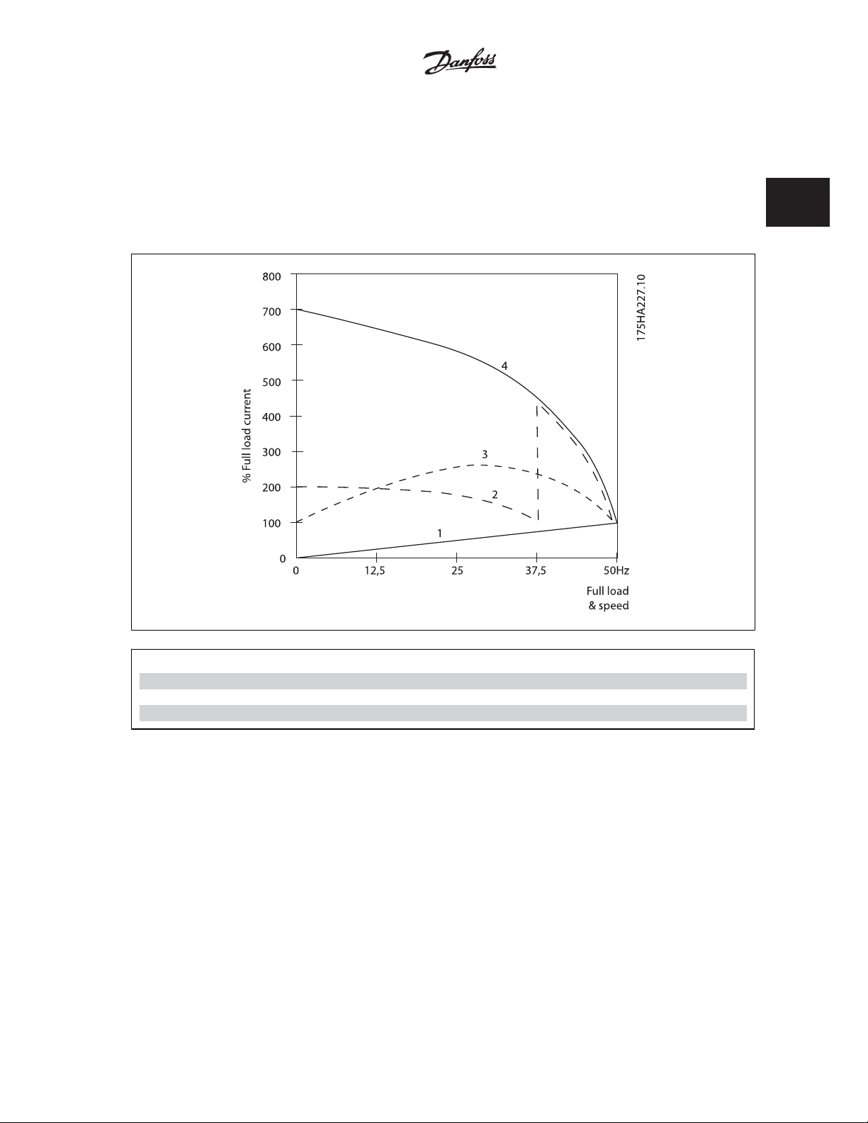
2.7.7 Star/delta Starter or Soft-starter not required
When larger motors are started, it is necessary in many countries to use equipment that limits the start-up current. In more tr aditional systems, a star/
delta starter or soft-starter is widely used. Such motor starters are not required if a frequency converter is used.
2
As illustrated in the figure below, a frequency converter does not consume more than rated current.
1 = VLT Automation VT Drive
2 = Star/delta starter
3 = Soft-starter
4 = Start directly on mains
MG.20.X1.22 - VLTp is a registered Danfoss trademark
23
Page 26
2
2 Introduction to VLT Automation VT Drive Automation VT Drive FC322 Design Guide
2.6 Control Structures
2.8.1 Control Principle
Illustration 2.3: Control structures.
The frequency converter is a high performance unit for demanding applications. It can handle various kinds of motor control principles such as U/f special
motor mode and VVC plus and can handle normal squirrel cage asynchronous motors.
Short circuit behavior on this FC depends on the 3 current transducers in the motor phases.
par. 1-00 Configuration Mode
In
is to be used
it can be selected if open or closed lo op
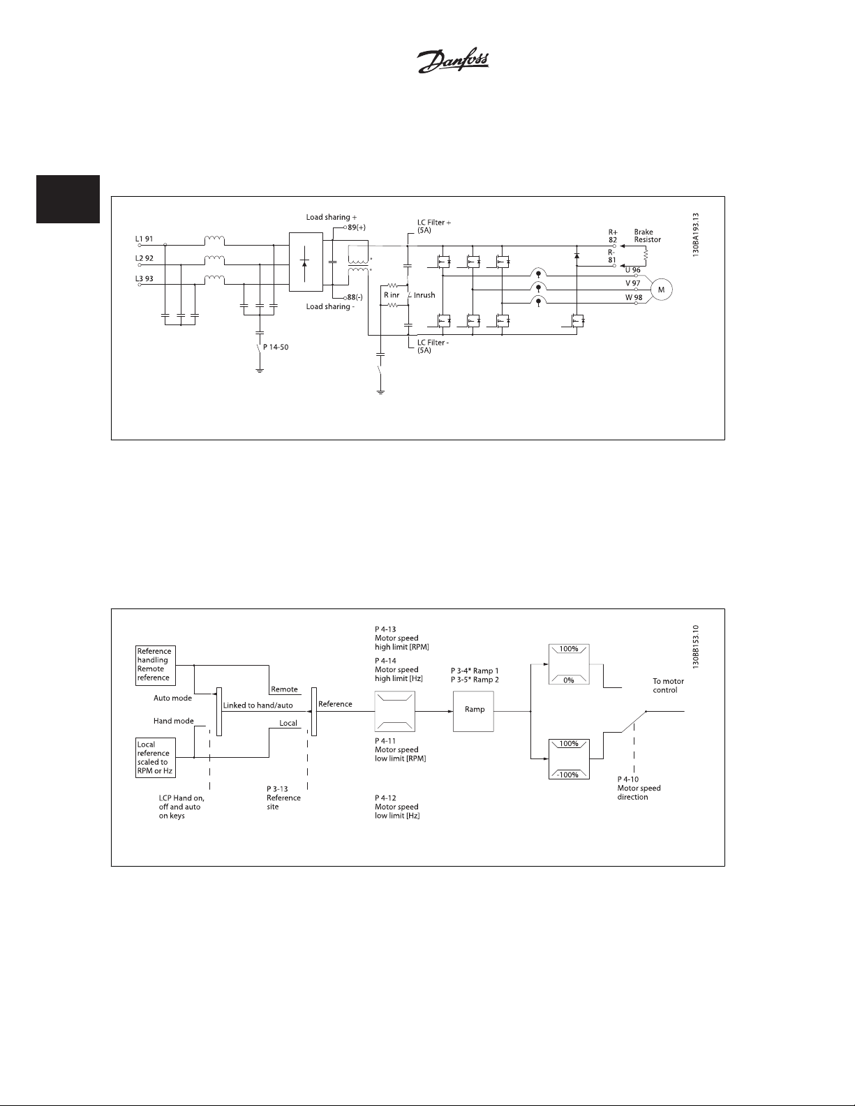
2.8.2 Control Structure Open Loop
Illustration 2.4: Open Loop structure.
In the configuration shown in the illustration above,
handling system or the local reference is received and fed through the ramp limitation and speed limitation before being sent to the motor control.
The output from the motor control is then limited by the maximum frequency limit.
par. 1-00 Configuration Mode
is set to Open loop [0]. The resulting reference from the reference
24
MG.20.X1.22 - VLTp is a registered Danfoss trademark
Page 27
0
Automation VT Drive FC322 Design Guide 2 Introduction to VLT Automation VT Drive
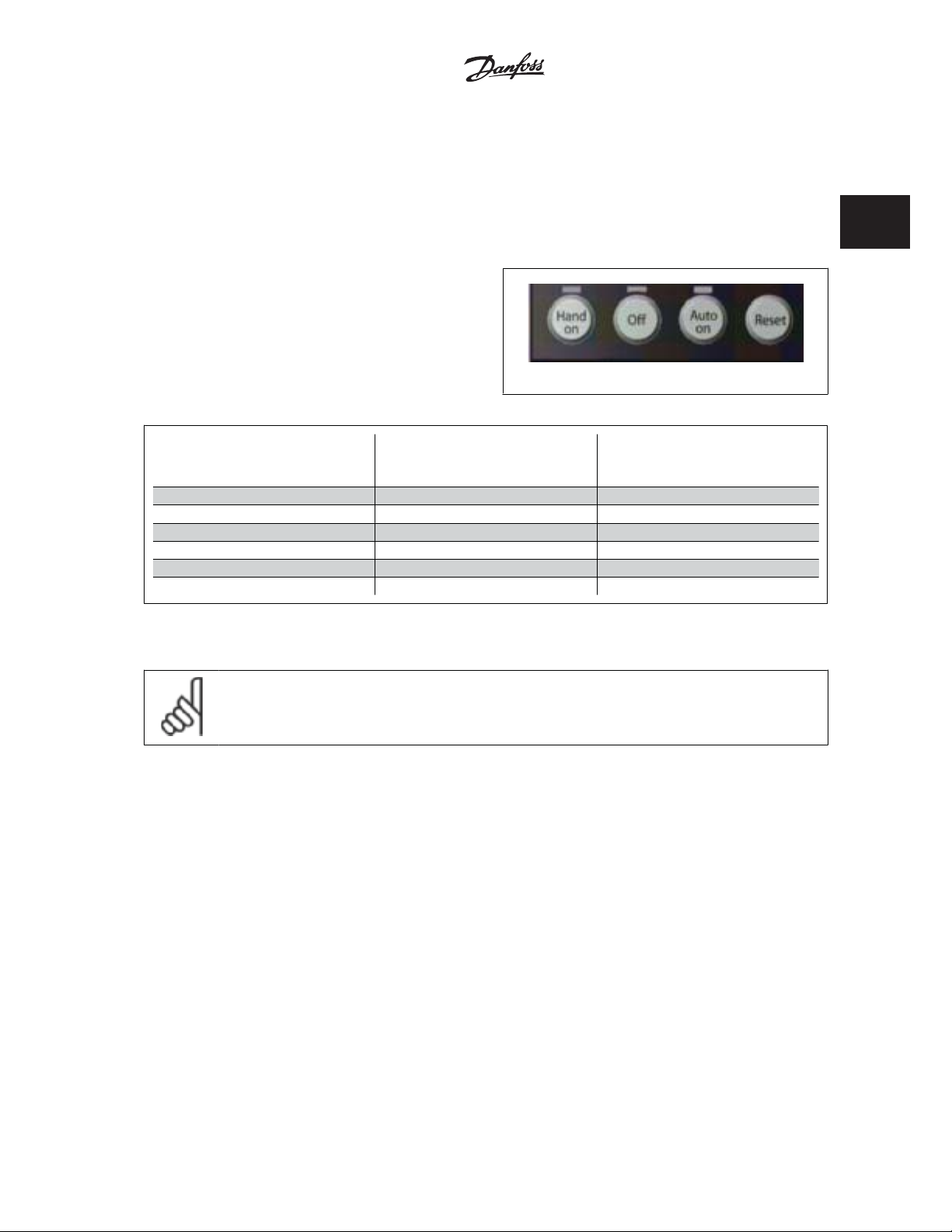
2.8.3 Local (Hand On) and Remote (Auto On) Control
The frequency converter can be operated manually via the local control panel (LCP) or remotely via analog/digital inputs or serial bus.
If allowed in par. 0-40
to start and stop the frequency converter byLCP using the [Hand ON] and [Off] keys. Alarms can be reset via the [RESET] key. After pressing the [Hand
On] key, the frequency converter goes into Hand Mode and follows (as default) the Local reference set by using the LCP arrow keys up [Ÿ] and down
[ź].
After pressing the [Auto On] key, the frequency converter goes into Auto
mode and follows (as default) the Remote reference. In this mode, it is
possible to control the frequency converter via the digital inputs and var-
ious serial interfaces (RS-485, USB, or an optional fieldbus). See more
about starting, stopping, changing ramps and parameter set-ups etc. in
par. group 5-1* (digital inputs) or par. group 8-5* (serial communica-
tion).
[Hand on] Key on LCP
, par. 0-41
[Off] Key on LCP
, par. 0-42
[Auto on] Key on LCP
, and par. 0-43
[Reset] Key on LCP
130BP046.1
, it is possible
2
Hand Off
Auto
LCP Keys
Hand Linked to Hand / Auto Local
Hand -> Off Linked to Hand / Auto Local
Auto Linked to Hand / Auto Remote
Auto -> Off Linked to Hand / Auto Remote
All keys Local Local
All keys Remote Remote
The table shows under which conditions either the Local Reference or the Remote Reference is active. One of them is always active, but both can not be
active at the same time.
NB!
Local Reference will be restored at power-down.
par. 1-00
Configuration Mode
is active (see table above for the conditions).
determines what kind of application control principle (i.e. Open Loop or Closed loop) is used when the Remote reference
Reference Site
par. 3-13
Reference Site
Active Reference
MG.20.X1.22 - VLTp is a registered Danfoss trademark
25
Page 28
2 Introduction to VLT Automation VT Drive Automation VT Drive FC322 Design Guide
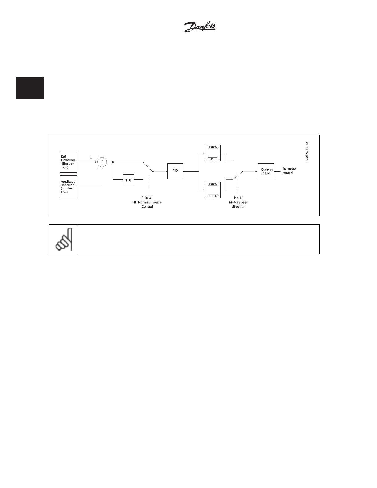
2.8.4 Control Structure Closed Loop
The closed loop controller allows the drive to become an integral part of the controlled system. The drive receives a feedback signal from a sensor in the
system. It then compares this feedback to a set-point reference value and determines the error, if any, between these two signals. It then adjusts the
speed of the motor to correct this error.
2
For example, consider a pump application where the speed of a pump is to be controlled so that the static pressure in a pipe is constant. The desired
static pressure value is supplied to the drive as the set-point reference. A static pressure sensor measures the actual static pressure in the pipe and
supplies this to the drive as a feedback signal. If the feedback signal is greater than the set-point reference, the drive will slow down to reduce the
pressure. In a similar way, if the pipe pressure is lower than the set-point reference, the drive will automatically speed up to increase the pressure provided
by the pump.
NB!
While the default values for the drive’s Closed Loop controller will often provide satisfactory performance, the control of the system
can often be optimized by adjusting some of the Closed Loop controller’s parameters. It is also possible to autotune the PI constants.
The figure is a block diagram of the drive’s Closed Loop controller. The details of the Reference Handling block and Feedback Handling block are described
in their respective sections below.
26
MG.20.X1.22 - VLTp is a registered Danfoss trademark
Page 29
Automation VT Drive FC322 Design Guide 2 Introduction to VLT Automation VT Drive
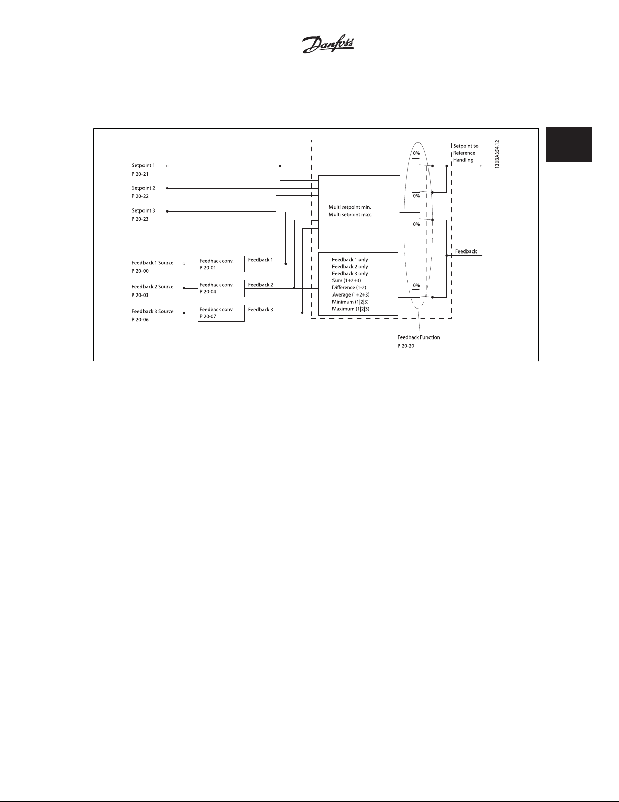
2.8.5 Feedback Handling
A block diagram of how the drive processes the feedback signal is shown below.
2
Feedback handling can be configured to work with applications requiring advanced control, such as multiple setpoints and multiple feedbacks. Three
types of control are common.
Single Zone, Single Setpoint
Single Zone Single Setpoint is a basic configuration. Setpoint 1 is added to any other reference (if any, see Reference Handling) and the feedback signal
is selected using par. 20-20.
Multi Zone, Single Setpoint
Multi Zone Single Setpoint uses two or three feedback sensors but only one setpoint. The feedbacks can be added, subtracted (only feedback 1 and 2)
or averaged. In addition, the maximum or minimum value may be used. Setpoint 1 is used exclusively in this configuration.
Multi Setpoint Min
If
attempts to keep all zones at or below their respective setpoints, while
setpoints.
Example:
A two zone two setpoint application Zone 1 setpoint is 15 bar and the feedback is 5.5 bar. Zone 2 setpoint is 4.4 bar and the feedback is 4.6 bar. If
Setpoint Max
setpoint, resulting in a negative difference). If
has the larger difference (feedback is lower than setpoint, resulting in a positive difference).
[13] is selected, the setpoint/feedback pair with the largest difference controls the speed of the drive.
Multi Setpoint Min
[14] is selected, Zone 1’s setpoint and feedback are sent to the PID controller, since this has the smaller difference (feedbac k i s higher th an
Multi Setpoint Min
[13] is selected, Zone 2’s setpoint and feedback is sent to the PID controller, since this
[13] attempts to keep all zones at or above their respective
Multi Setpoint Maximum
[14]
Multi
MG.20.X1.22 - VLTp is a registered Danfoss trademark
27
Page 30
2
2 Introduction to VLT Automation VT Drive Automation VT Drive FC322 Design Guide
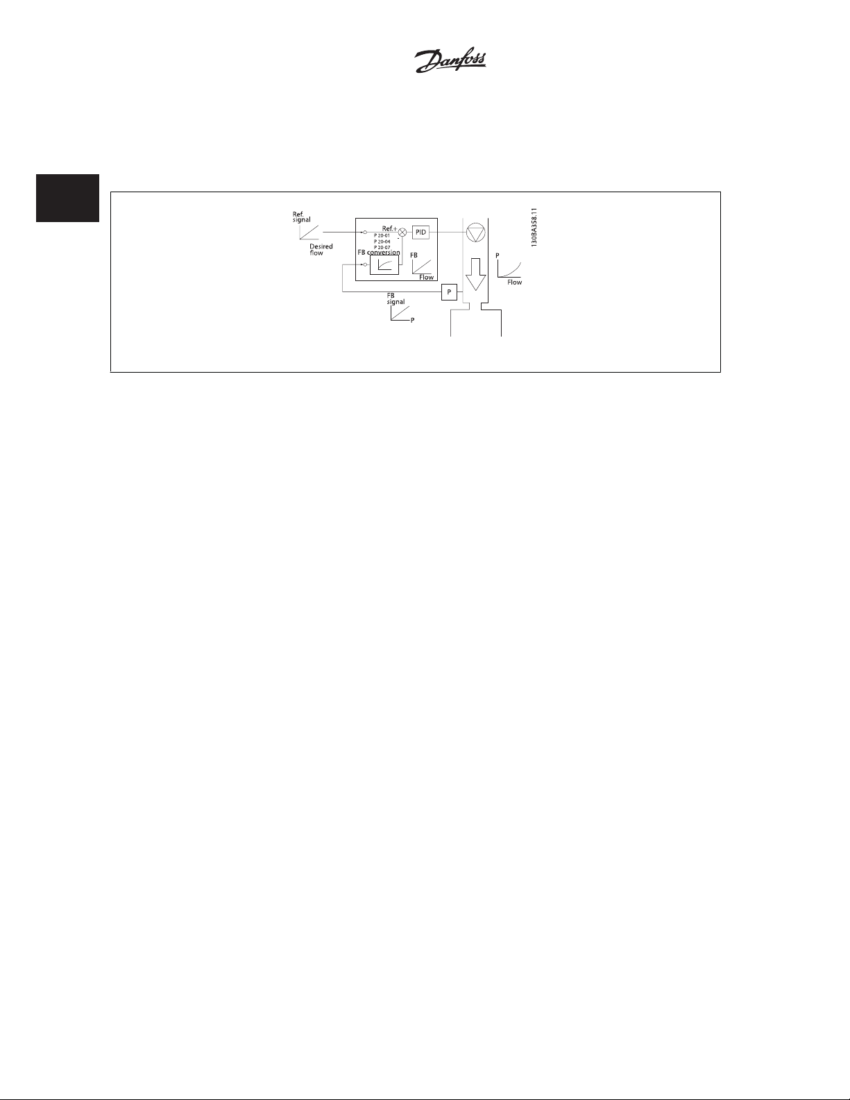
2.8.6 Feedback Conversion
In some applications it may be useful to convert the feedback signal. One example of this is using a pressure signal to provide flow feedback. Since the
square root of pressure is proportional to flow, the square root of the pressure signal yields a value proportional to the flow. This is shown below.
2.8.7 Reference Handling
Details for Open Loop and Closed Loop operation.
A block diagram of how the drive produces the Remote Reference is shown below:.
28
MG.20.X1.22 - VLTp is a registered Danfoss trademark
Page 31

Automation VT Drive FC322 Design Guide 2 Introduction to VLT Automation VT Drive
2
MG.20.X1.22 - VLTp is a registered Danfoss trademark
29
Page 32

2
2 Introduction to VLT Automation VT Drive Automation VT Drive FC322 Design Guide
The Remote Reference is comprised of:
• Preset references.
• External references (analog inputs, pulse frequency inputs, digital potentiometer inputs and serial communication bus references).
• The Preset relative reference.
• Feedback controlled setpoint.
Up to 8 preset references can be programmed in the drive. The active preset reference can be selected using digital inputs or the serial communications
bus. The reference can also be supplied externally, most commonly from an analog input. This external source is selected by one of the 3 Reference
Source parameters (par. 3-15
This is also commonly called a Speed Up/Speed Down Control or a Floating Point Control. To set it up, one digital input is programmed to increase the
reference while another digital input is programmed to decrease the reference. A third digital input can be used to reset the Digipot reference. All reference
resources and the bus reference are added to produce the total External Reference. The External Reference, the Preset Reference or the sum of the two
can be selected to be the active reference. Finally, this reference can by be scaled using par. 3-14
The scaled reference is calculated as follows:
Reference
Where X is the external reference, the preset reference or the sum of these and Y is par. 3-14
= X + X ×
NB!
If Y, par. 3-14
Reference 1 Source
Y
(
)
100
Preset Relative Reference
, par. 3-16
Reference 2 Source
is set to 0%, the reference will not be affected by the scaling
and par. 3-17
Reference 3 Source
Preset Relative Reference
Preset Relative Reference
). Digipot is a digital potentiometer.
.
in [%].
30
MG.20.X1.22 - VLTp is a registered Danfoss trademark
Page 33

Automation VT Drive FC322 Design Guide 2 Introduction to VLT Automation VT Drive
2.8.8 Example of Closed Loop PID Control
The following is an example of a Closed Loop Control for a booster pump application:
2
In a water distribution system, the pressure is to be maintained at a constant value. The desired pressure (setpoint) is set between 0 and 10 Bar using
a 0-10 volt potentiometer or can be set by a parameter. The pressure sensor has a range of 0 to 10 Bar and uses a two-wire transmitter to provide a
4-20 mA signal. The output frequency range of the drive is 10 to 50 Hz.
1. Start/Stop via switch connected between terminals 12 (+24 V) and 18.
2. Pressure reference via a potentiometer (0-10 Bar, 0-10 V) connected
to terminals 50 (+10 V), 53 (input) and 55 (common).
3. Pressure feedback via transmitter (0-10 Bar, 4-20 mA) connected to
terminal 54. Switch S202 behind the Local Control Panel set to ON
(current input).
MG.20.X1.22 - VLTp is a registered Danfoss trademark
31
Page 34

2
2 Introduction to VLT Automation VT Drive Automation VT Drive FC322 Design Guide
2.8.9 Programming Order
Function Par. no. Setting
1) Make sure the motor runs properly. Do the following:
Hz
Set the drive to control the motor based on drive output fre-
quency.
Set the motor parameters using nameplate data. 1-2* As specified by motor name plate
Run Automatic Motor Adaptation. 1-29
2) Check that the motor is running in the right direction.
Press the “Hand On” LCP key and the ^ key to make the
motor turn slowly. Check that the motor runs in the correct
direction.
3) Make sure the frequency converter limits are set to safe values
Check that the ramp settings are within capabilities of the
drive and allowed application operating specifications.
Prohibit the motor from reversing (if necessary) 4-10
Set acceptable limits for the motor speed. 4-12
Switch from open loop to closed loop. 1-00
4) Configure the feedback to the PID controller.
Set up Analog Input 54 as a feedback input. 20-00
Select the appropriate reference/feedback unit. 20-12
5) Configure the setpoint reference for the PID controller.
Set acceptable limits for the setpoint reference. 3-02
Set up Analog Input 53 as Reference 1 Source. 3-15
6) Scale the analog inputs used for setpoint reference and feedback.
Scale Analog Input 53 for the pressure range of the potenti-
ometer (0 - 10 Bar, 0 - 10 V).
Scale Analog Input 54 for pressure sensor (0 - 10 Bar, 4 - 20
mA)
7) Tune the PID controller parameters.
Adjust the drive’s Closed Loop Controller, if needed. 20-93
8) Finished!
Save the parameter setting to the LCP for safe keeping 0-50
0-02
If the motor runs in the wrong direction, remove power
3-41
3-42
4-14
4-19
3-03
6-10
6-11
6-14
6-15
6-22
6-23
6-24
6-25
20-94
[1]
Enable complete AMA
temporarily and reverse two of the motor phases.
60 sec.
60 sec.
Depends on motor/load size!
Also active in Hand mode.
Clockwise
[0]
10 Hz,
Motor min speed
50 Hz,
Motor max speed
50 Hz,
Drive max output frequency
Closed Loop
Analog input 54
Bar
[71]
0 Bar
10 Bar
Analog input 53
0 V
10 V (default)
0 Bar
10 Bar
4 mA
20 mA (default)
0 Bar
10 Bar
See Optimization of the PID Controller, below.
All to LCP
[1]
[1] and then run the AMA function.
[3]
[2] (default)
[1] (default)
32
MG.20.X1.22 - VLTp is a registered Danfoss trademark
Page 35

Automation VT Drive FC322 Design Guide 2 Introduction to VLT Automation VT Drive
2.8.10 Tuning the Drive Closed Loop Controller
Once the drive’s Closed Loop Controller has been set up, the performance of the controller should be tested. In many cases, its performance may be
acceptable using the default values of PID Proportional Gain (par. 20-93) and PID Integral Time (par. 20-94). However, in some cases it may be helpful
to optimize these parameter values to provide faster system response while still controlling speed overshoot.
2.8.11 Manual PID Adjustment
1. Start the motor
2. Set par. 20-93 (PID Proportional Gain) to 0.3 and increase it until the feedback signal begins to oscillate. If necessary, start and stop the drive
or make step changes in the set-point reference to attempt to cause oscillation. Next reduce the PID Proportional Gain until the feedback signal
stabilizes. Then reduce the proportional gain by 40-60%.
3. Set par. 20-94 (PID Integral Time) to 20 sec. and reduce it until the feedback signal begins to oscillate. If necessary, start and stop the drive
or make step changes in the set-point reference to attempt to cause oscillation. Next, increase the PID Integral Time until the feedback signal
stabilizes. Then increase of the Integral Time by 15-50%.
4. Par. 20-95 (PID Differential Time) should only be used for very fast-acting systems. The typical value is 25% of the PID Integral Time (par.
20-94). The differential function should only be used when the setting of the proportional gain and the integral time has been fully optimized.
Make sure that oscillations of the feedback signal are sufficiently dampened by the low-pass filter for the feedback signal (par 6 16, 6 26, 5 54
or 5 59, as required).
2
MG.20.X1.22 - VLTp is a registered Danfoss trademark
33
Page 36

2 Introduction to VLT Automation VT Drive Automation VT Drive FC322 Design Guide
2.7 General aspects of EMC
2.9.1 General Aspects of EMC Emissions
2
Electrical interference is usually conducted at frequences in the range 150 kHz to 30 MHz. Airborne interference from the drive system in the range 30
MHz to 1 GHz is generated from the inverter, motor cable, and the motor.
As shown in the illustration below, capacitive currents in the motor cable coupled with a high dV/dt from the motor voltage generate leakage currents.
The use of a screened motor cable increases the leakage current (see illustration below) because screened cables have higher capacitance to earth than
unscreened cables. If the leakage current is not filtered, it will cause greater interference on the mains in the radio frequency range below approx. 5
MHz. Since the leakage current (I
from the screened motor cable according to the below figure.
The screen reduces the radiated interference but increases the low-frequency interference on the mains. The motor cable screen must be connected to
the frequency converter enclosure as well as on the motor enclosure. This is best done by using integrated screen clamps so as to avoid twisted screen
ends (pigtails). These increase the screen impedance at higher frequencies, which reduces the screen effect and increases the leakage current (I
If a screened cable is used for Fieldbus, relay, control cable, signal interface and brake, the screen must be mounted on the enclosure at both ends. In
some situations, however, it will be necessary to break the screen to avoid current loops.
) is carried back to the unit through the screen (I 3), there will in principle only be a small electro-magnetic field (I4)
1
).
4
If the screen is to be placed on a mounting plate for the frequency converter, the mounting plate must be made of metal, because the screen currents
have to be conveyed back to the unit. Moreover, ensure good electrical contact from the mounting plate through the mounting screws to the frequency
converter chassis.
NB!
When unscreened cables are used, some emission requirements are not complied with, although the immunity requirements are ob-
served.
In order to reduce the interference level from the entire system (unit + installation), make motor and brake cables as short as possible. Avoid placing
cables with a sensitive signal level alongside motor and brake cables. Radio interference higher than 50 MHz (airborne) is especially generated by the
control electronics.
34
MG.20.X1.22 - VLTp is a registered Danfoss trademark
Page 37

Automation VT Drive FC322 Design Guide 2 Introduction to VLT Automation VT Drive
2.9.2 Emission Requirements
According to the EMC product standard for adjustable speed frequency converters EN/IEC61800-3:2004 the EMC requirements depend on the intended
use of the frequency converter. Four categories are defined in the EMC product standard. The definitions of the four categories together with the
requirements for mains supply voltage conducted emissions are given in the table below:
2
Conducted emission requirement
Category Definition
C1 frequency converters installed in the first environment (home and office) with a supply
voltage less than 1000 V.
C2 frequency converters installed in the first environment (home and office) with a supply
voltage less than 1000 V, which are neither plug-in nor movable and are intended to be
installed and commissioned by a professional.
C3 frequency converters installed in the second environment (industrial) with a supply volt-
age lower than 1000 V.
C4 frequency converters installed in the second environment with a supply voltage above
1000 V and rated current above 400 A or intended for use in complex systems.
When the generic emission standards are used the frequency converters are required to comply with the following limits:
Environment Generic standard
First environment
(home and office)
Second environment
(industrial environment)
EN/IEC61000-6-3 Emission standard for residential, commercial and
light industrial environments.
EN/IEC61000-6-4 Emission standard for industrial environments. Class A Group 1
according to the limits given in
EN55011
Class B
Class A Group 1
Class A Group 2
No limit line.
An EMC plan should be made.
Conducted emission requirement ac-
cording to the limits given in
EN55011
Class B
MG.20.X1.22 - VLTp is a registered Danfoss trademark
35
Page 38

2
2 Introduction to VLT Automation VT Drive Automation VT Drive FC322 Design Guide
2.9.3 EMC Test Results (Emission)
The following test results have been obtained using a system with a frequency converter (with options if relevant), a screened control cable, a
control box with potentiometer, as well as a motor and motor screened cable.
Phas
RFI filter type
Setup: S / T
H1 meter meter meter
1.1-22 kW 220-240 V S2 150 150 50 Yes No
0.25-45 kW 200-240 V T2 150 150 50 Yes No
7.5-37 kW 380-480 V S4 150 150 50 Yes No
0.37-90 kW 380-480 V T4 150 150 50 Yes No
H2
1.1-22 kW 220-240 V S2 25 No No No No
0.25-3.7 kW 200-240 V T2 5NoNo No No
5.5-45 kW 200-240 V T2 25 No No No No
0.37-7.5 kW 380-480 V T4 5NoNo No No
7.5-37 kW 380-480 V S4 25 No No No No
11-90 kW 380-480 V T4 25 No No No No
110-1000 kW 380-480 V T4 50 No No No No
0.75-90 kW 525-600 V T6 150 No No No No
11-90 kW 525-690 V T7 Yes No No No No
45-1200 kW 525-690 V T7 150 No No No No
H3
0.25-45 kW 200-240 V T2 75 50 10 Yes No
0.37-90 kW 380-480 V T4 75 50 10 Yes No
H4
110-1000 kW 380-480 V T4 150 150 No Yes No
11-90 kW 525-690 V T7 No Yes No Yes No
45-400 kW 525-690 V T7 150 30 No No No
Hx
0.75-90 kW 525-600 V T6 -- - - -
e
type
EN 55011 ClassA2EN 55011
Conducted emission.
Maximum shielded cable length.
Industrial environment
Class A1
Housing, trades
and light indus-
tries
EN 55011 Class
B
Radiated emission
Industrial environ-
ment
EN 55011 Class A1 EN 55011 Class B
Housing, trades and
light industries
Table 2.1: EMC Test Results (Emission)
2.9.4 General Aspects of Harmonics Emission
A frequency converter takes up a non-sinusoidal current from mains,
which increases the input current I
formed by means of a Fourier analysis and split up into sine-wave cur-
rents with different frequencies, i.e. different harmonic currents I
50 Hz as the basic frequency:
The harmonics do not affect the power consumption directly but increase
the heat losses in the installation (transformer, cables). Consequently, in
36
. A non-sinusoidal current is trans-
RMS
MG.20.X1.22 - VLTp is a registered Danfoss trademark
N
with
Harmonic currents I
1
I
5
I
7
Hz 50 Hz 250 Hz 350 Hz
Page 39

Automation VT Drive FC322 Design Guide 2 Introduction to VLT Automation VT Drive
plants with a high percentage of rectifier load, maintain harmonic cur-
rents at a low level to avoid overload of the transformer and high tem-
perature in the cables.
2
NB!
Some of the harmonic currents might disturb communication equipment connected to the same transformer or cause resonance in
connection with power-factor correction batteries.
NB!
To ensure low harmonic currents, the frequency converter is equipped with intermediate circuit coils as standard. This normally reduces
the input current I
The voltage distortion on the mains supply voltage depends on the size of the harmonic currents multiplied by the mains impedance for the frequency
in question. The total voltage distortion THD is calculated on the basis of the individual voltage harmonics using this formula:
RMS
by 40%.
THD
%=
2
5
+
2
U
+ ... +
7
U
2
U
N
(UN% of U)
2.9.5 Harmonics Emission Requirements
Equipment connected to the public supply network:
Options: Definition:
1 IEC/EN 61000-3-2 Class A for 3-phase balanced equip-
ment (for professional equipment only up to 1 kW total
power).
2 IEC/EN 61000-3-12 Equipment 16A-75A and professio-
nal equipment as from 1 kW up to 16A phase current.
2.9.6 Harmonics Test Results (Emission)
Power sizes up to PK75 in T2 and T4 complies with IEC/EN 61000-3-2 Class A. Power sizes from P1K1 and up to P18K in T2 and up to P90K in T4 complies
with IEC/EN 61000-3-12. Power sizes P110 - P450 in T4 also complies with IEC/EN 61000-3-12 even though not required because currents are above 75
A.
Table 4, R
S
SC
at the interface point between the user’s supply and the public system.
It is the responsibility of the installer or user of the equipment to ensure, by consultation with the distribution network operator if necessary, that the
equipment is connected only to a supply with a short-circuit power S
Other power sizes can be connected to the public supply network by consultation with the distribution network operator.
>= 120, THD <= 48% and PWHD >=46% provided that the short-circuit power of the supply Ssc is greater than or equal to:
sce
= 3 ×
R
×
U
×
I
SCE
mains
= 3 × 120 × 400 ×
equ
I
equ
greater than or equal to specified above.
sc
MG.20.X1.22 - VLTp is a registered Danfoss trademark
37
Page 40

2
2 Introduction to VLT Automation VT Drive Automation VT Drive FC322 Design Guide
2.8 Immunity Requirements
The immunity requirements for frequency converters depend on the environment where they are installed. The requirements for the industrial environment
are higher than the requirements for the home and office environment. All Danfoss frequency converters comply with the requirements for the industrial
environment and consequently comply also with the lower requirements for home and office environment with a large safety margin.
In order to document immunity against electrical interference from electrical phenomena, the following immunity tests have been made on a system
consisting of a frequency converter (with options if relevant), a screened control cable and a control box with potentiometer, motor cable and motor.
The tests were performed in accordance with the following basic standards:
• EN 61000-4-2 (IEC 61000-4-2): Electrostatic discharges (ESD): Simulation of electrostatic discharges from human beings.
• EN 61000-4-3 (IEC 61000-4-3): Incoming electromagnetic field radiation, amplitude modulated simulation of the effects of radar and radio
communication equipment as well as mobile communications equipment.
• EN 61000-4-4 (IEC 61000-4-4): Burst transients: Simulation of interference brought about by switching a contactor, relay or similar devices.
• EN 61000-4-5 (IEC 61000-4-5): Surge transients: Simulation of transients brought about e.g. by lightning that strikes near installations.
• EN 61000-4-6 (IEC 61000-4-6): RF Common mode: Simulation of the effect from radio-transmission equipment joined by connection cables.
See following EMC immunity form.
Voltage range: 200-240 V, 380-480 V
Basic standard Burst
IEC 61000-4-4
Acceptance criterion B B B A A
Line
Motor
4 kV CM
4 kV CM
Brake 4 kV CM
Load sharing 4 kV CM
Control wires
2 kV CM
Standard bus 2 kV CM
Relay wires 2 kV CM
Application and Fieldbus op-
2 kV CM
tions
LCP cable
External 24 V DC
Enclosure
2 kV CM
2 kV CM
— —
AD: Air Discharge
CD: Contact Discharge
CM: Common mode
DM: Differential mode
1. Injection on cable shield.
Surge
IEC 61000-4-5
2 kV/2 DM
4 kV/12 CM
4 kV/2
1)
4 kV/2
1)
4 kV/2
2 kV/2
2 kV/2
2 kV/2
2 kV/2
2 kV/2
0.5 kV/2 DM
1 kV/12 CM
ESD
IEC
61000-4-2
1)
1)
1)
1)
1)
1)
8 kV AD
6 kV CD
Radiated electromagnetic field
IEC 61000-4-3
— —
——
— —
——
— —
——
— —
——
— —
——
10 V/m —
RF common
mode voltage
IEC 61000-4-6
10 V
RMS
10 V
RMS
10 V
RMS
10 V
RMS
10 V
RMS
10 V
RMS
10 V
RMS
10 V
RMS
10 V
RMS
10 V
RMS
Table 2.2: Immunity
38
MG.20.X1.22 - VLTp is a registered Danfoss trademark
Page 41

Automation VT Drive FC322 Design Guide 2 Introduction to VLT Automation VT Drive
2.9 Galvanic isolation (PELV)
2.11.1 PELV - Protective Extra Low Voltage
PELV offers protection by way of extra low voltage. Protection against electric shock is ensured when the electrical supply is of the PELV type and the
installation is made as described in local/national regulations on PELV supplies.
All control terminals and relay terminals 01-03/04-06 comply with PELV (Protective Extra Low Voltage) (Does not apply to grounded Delta leg above 400
V).
Galvanic (ensured) isolation is obtained by fulfilling requirements for higher isolation and by providing the relevant creapage/clearance distances. These
requirements are described in the EN 61800-5-1 standard.
The components that make up the electrical isolation, as described below, also comply with the requirements for higher isolation and the relevant test
as described in EN 61800-5-1.
The PELV galvanic isolation can be shown in six locations (see illustration):
In order to maintain PELV all connections made to the control terminals must be PELV, e.g. thermistor must be reinforced/double insulated.
1. Power supply (SMPS) incl. signal isolation of U
intermediate current voltage.
2. Gate drive that runs the IGBTs (trigger transformers/opto-cou-
plers).
3. Current transducers.
4. Opto-coupler, brake module.
5. Internal inrush, RFI, and temperature measurement circuits.
6. Custom relays.
, indicating the
DC
Illustration 2.5: Galvanic isolation
2
The functional galvanic isolation (a and b on drawing) is for the 24 V back-up option and for the RS 485 standard bus interface.
Installation at high altitude:
380 - 500 V, enclosure A, B and C: At altitudes above 2 km, please contact Danfoss regarding PELV.
380 - 500 V, enclosure D, E and F: At altitudes above 3 km, please contact Danfoss regarding PELV.
525 - 690 V: At altitudes above 2 km, please contact Danfoss regarding PELV.
MG.20.X1.22 - VLTp is a registered Danfoss trademark
39
Page 42

2
2 Introduction to VLT Automation VT Drive Automation VT Drive FC322 Design Guide
2.10 Earth leakage current
Warning:
Touching the electrical ts may be fatal - even after the equipment has been disconnected from mains.
Also make sure that other voltage inputs have been disconnected, such a s load sharing (linkage of DC intermediate circuit), as well as
the motor connection for kinetic back-up.
Before touching any electrical parts, wait at least the amount of time indicated in the
Shorter time is allowed only if indicated on the nameplate for the specific unit.
Leakage Current
The earth leakage current from the frequency converter exceeds 3.5 mA. To ensure that the earth cable has a good mechanical
connection to the earth connection (terminal 95), the cable cross section must be at least 10 mm
seately.
Residual Current Device
This product can cause a d.c. current in the protective conductor. Where a residual current device (RCD) is used for protection in case
of di rect o r i ndir ect co nt act , on ly an RC D of Ty pe B is a llowe d o n the supply s ide o f this pr oduc t. Oth er wise , anot he r pro tecti ve measure
shall be applied, such as separation from the environment by double or reinforced insulation, or isolation from the supply system by a
transformer. See also RCD Application Note MN.90.GX.02.
Protective earthing of the frequency converter and the use of RCD's must always follow national and local regulations.
Safety Precautions
2
or 2 rated earth wires terminated
section.
40
MG.20.X1.22 - VLTp is a registered Danfoss trademark
Page 43

Automation VT Drive FC322 Design Guide 2 Introduction to VLT Automation VT Drive
2.11 Control with Brake Function
2.13.1 Selection of Brake Resistor
In certain applications, for instance centrifuges, it is desirable to bring the motor to a stop more rapidly than can be achieved through controlling via
ramp down or by free-wheeling. In such applications, dynamic braking with a braking resistor may be utilized. Using a braking resistor ensures that the
energy is absorbed in the resistor and not in the frequency converter.
If the amount of kinetic energy transferred to the resistor in each braking period is not known, the average power can be calculated on the basis of the
cycle time and braking time also called intermitted duty cycle. The resistor intermittent duty cycle is an indication of the duty cycle at which the resistor
is active. The below figure shows a typical braking cycle.
The intermittent duty cycle for the resistor is calculated as follows:
Duty Cycle = tb/T
T = cycle time in seconds
is the braking time in seconds (as part of the total cycle time)
t
b
2
Danfoss offers brake resistors with duty cycle of 5%, 10% and 40% suitable for use with the Automation VT Drive FC322 series. If a 10% duty cycle
resistor is applied, this is able of absorbing braking power upto 10% of the cycle time with the remaining 90% being used to dissipate heat from the
resistor.
For further selection advice, please contact Danfoss.
NB!
If a short circuit in the brake transistor occurs, power dissipation in the brake resistor is only prevented by using a mains switch or
contactor to disconnect the mains for the frequency converter. (The contactor can be controlled by the frequency converter).
MG.20.X1.22 - VLTp is a registered Danfoss trademark
41
Page 44

2
2 Introduction to VLT Automation VT Drive Automation VT Drive FC322 Design Guide
2.13.2 Control with Brake Function
The brake is protected against short-circuiting of the brake resistor, and the brake transistor is monitored to ensure that short-circuiting of the transistor
is detected. A relay/digital output can be used for protecting the brake resistor against overloading in connection with a fault in the frequency converter.
In addition, the brake makes it possible to read out the momentary power and the mean power for the latest 120 seconds. The brake can also monitor
the power energizing and make sure it does not exceed a limit selected in par. 2-12
the function to carry out when the power transmitted to the brake resistor exceeds the limit set in par. 2-12
NB!
Monitoring the brake power is not a safety function; a thermal switch is required for that purpose. The brake resistor circuit is not earth
leakage protected.
Brake Power Limit (kW)
. In par. 2-13
Brake Power Limit (kW)
Brake Power Monitoring
, select
.
Over voltage control (OVC)
active for all units. The function ensures that a trip can be avoided if the DC link voltage increases. This is done by increasing the output frequency to
limit the voltage from the DC link. It is a very useful function, e.g. if the ramp-down time is too short since tripping of the frequency converter is avoided.
In this situation the ramp-down time is extended.
(exclusive brake resistor) can be selected as an alternative brake function in par. 2-17
Over-voltage Control
. This function is
2.12 Mechanical Brake Control
2.14.1 Brake Resistor Cabling
EMC (twisted cables/shielding)
To reduce the electrical noise from the wires between the brake resistor and the frequency converter, the wires must be twisted.
For enhanced EMC performance a metal screen can be used.
2.13 Extreme Running Conditions
Short Circuit (Motor Phase – Phase)
The frequency converter is protected against short circuits by means of current measurement in each of the three motor phases or in the DC link. A short
circuit between two output phases will cause an overcurrent in the inverter. The inverter will be turned off individually when the short circuit current
exceeds the permitted value (Alarm 16 Trip Lock.
To protect the drive against a short circuit at the load sharing and brake outputs please see the design guidelines.
Switching on the Output
Switching on the output between the motor and the frequency converter is fully permitted. You cannot damage the frequency converter in any way by
switching on the output. However, fault messages may appear.
Motor-generated Overvoltage
The voltage in the intermediate circuit is increased when the motor acts as a generator.
This occurs in following cases:
1. The load drives the motor, ie. the load generates energy.
2. During deceleration ("ramp-down") if the moment of inertia is high, the friction is low and the ramp-down time is too short for the energy to be
dissipated as a loss in the frequency converter, the motor and the installation.
3. In-correct slip compensation setting may cause higher DC link voltage.
The control unit may attempt to correct the ramp if possible (par. 2-17
The inverter turns off to protect the transistors and the intermediate circuit capacitors when a certain voltage level is reach ed.
See par. 2-10 and par. 2-17 to select the method used for controlling the intermediate circuit voltage level.
Over-voltage Control
.
High Temperature
High ambient temperature may overheat the frequency converter.
42
MG.20.X1.22 - VLTp is a registered Danfoss trademark
Page 45

Automation VT Drive FC322 Design Guide 2 Introduction to VLT Automation VT Drive
Mains Drop-out
During a mains drop-out, the frequency converter keeps running until the intermediate circuit voltage drops below the minimum stop level, which is
typically 15% below the frequency converter's lowest rated supply voltage.
The mains voltage before the drop-out and the motor load determines how long it takes for the inverter to coast.
plus
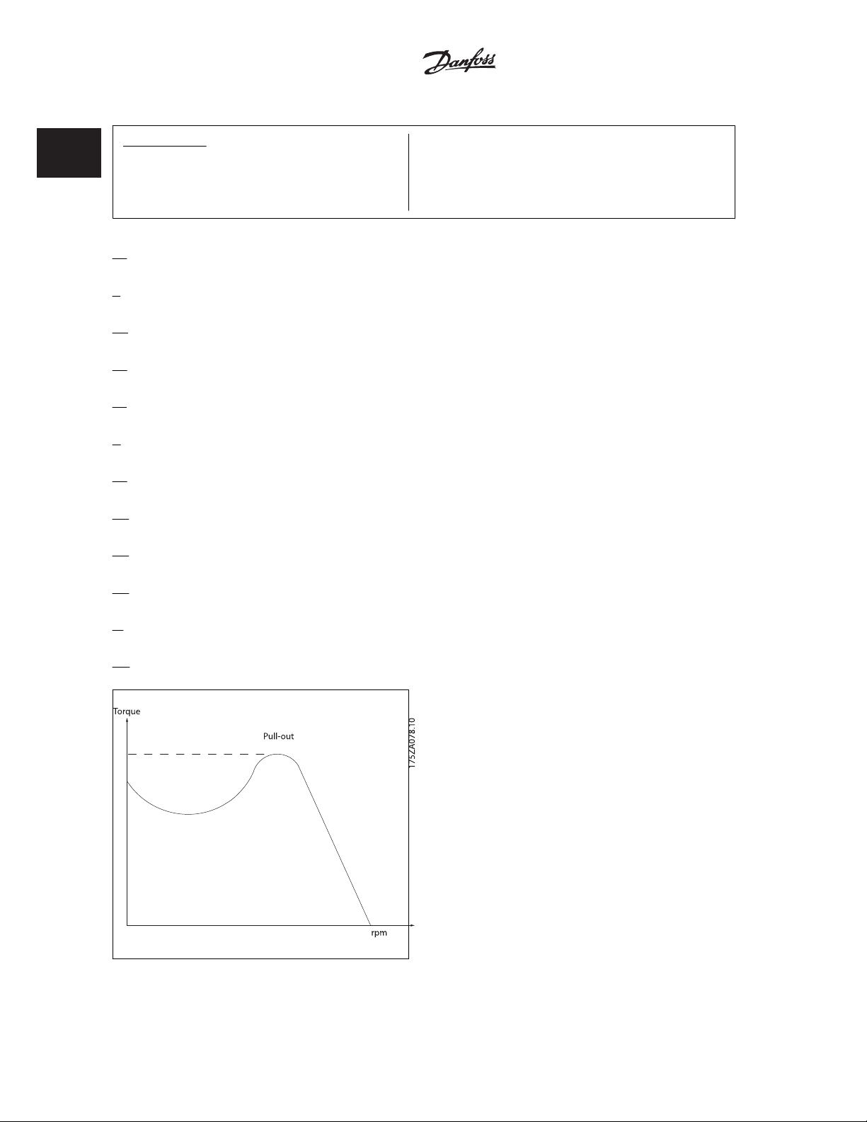
Static Overload in VVC
When the frequency converter is overloaded (the torque limit in par. 4-16/4-17 is reached), the controls reduces the output frequency to reduce the load.
If the overload is excessive, a current may occur that makes the frequency converter cut out after approx. 5-10 s.
Operation within the torque limit is limited in time (0-60 s) in par. 14-25.
2.15.1 Motor Thermal Protection
This is the way Danfoss is protecting the motor from being overheated. It is an electronic feature that simulates a bimetal relay based on internal
measurements. The characteristic is shown in the following figure:
mode
2
Illustration 2.6: The X-axis is showing the ratio between I
cuts off and trips the drive. The curves are showing the characteristic nominal speed at twice the nominal speed and at 0,2x the nominal
speed.
It is clear that at lower speed the ETR cuts of at lower heat due to less cooling of the motor. In that way the motor are protected from being over heated
even at low speed. The ETR feature is calculating the motor temperature based on actual current and speed. The calculated temperature is visible as a
read out parameter in par. 16-18
The thermistor cut-out value is > 3 k.
Integrate a thermistor (PTC sensor) in the motor for winding protection.
Motor protection can be implemented using a range of techniques: PTC
sensor in motor windings; mechanical thermal switch (Klixon type); or
Electronic Thermal Relay (ETR).
Motor Thermal
in the frequency converter.
motor
and I
nominal. The Y- axis is showing the time in seconds before the ETR
motor
MG.20.X1.22 - VLTp is a registered Danfoss trademark
43
Page 46

2
2 Introduction to VLT Automation VT Drive Automation VT Drive FC322 Design Guide
44
MG.20.X1.22 - VLTp is a registered Danfoss trademark
Page 47

Automation VT Drive FC322 Design Guide 2 Introduction to VLT Automation VT Drive
Using a digital input and 24 V as power supply:
Example: The frequency converter trips when the motor temperature is
too high.
Parameter set-up:
Set par. 1-90
Set par. 1-93
Motor Thermal Protection
Thermistor Source
to
Digital Input 33
to
Thermistor Trip
[2]
[6]
2
Using a digital input and 10 V as power supply:
Example: The frequency converter trips when the motor temperature is
too high.
Parameter set-up:
Set par. 1-90
Set par. 1-93
Using an analog input and 10 V as power supply:
Example: The frequency converter trips when the motor temperature is
too high.
Parameter set-up:
Set par. 1-90
Set par. 1-93
Do not select a reference source.
Motor Thermal Protection
Thermistor Source
to
Digital Input 33
Motor Thermal Protection
Thermistor Source
to
Analog Input 54
to
Thermistor Trip
to
Thermistor Trip
[2]
[6]
[2]
[2]
Input
Digital/analog
Digital 24 V < 6.6 k - > 10.8 k
Digital 10 V < 800 - > 2.7 k
Analog 10 V < 3.0 k - > 3.0 k
NB!
Check that the chosen supply voltage follows the specification of the used thermistor element.
Summary
With the Torque limit feature the motor is protected for being overloaded independent of the speed. With the ETR the motor is protected for being over
heated and there is no need for any further motor protection. That means when the motor is heated up the ETR timer controls for how long time the
motor can be running at the high temperature before it is stopped in order to prevent over heating. If the motor is overloaded without reaching the
temperature where the ETR shuts of the motor, the torque limit is protecting the motor and application for being overloaded.
Supply Voltage
Volt
MG.20.X1.22 - VLTp is a registered Danfoss trademark
Threshold
Cut-out Values
45
Page 48

2
2 Introduction to VLT Automation VT Drive Automation VT Drive FC322 Design Guide
NB!
ETR is a cti vated in par. and is con tro lled in par. 4 -16
is set in par. 14-25
Trip Delay at Torque Limit
Torque Limit Motor Mode
.
. The time before the torque limit warning trips the frequency converter
46
MG.20.X1.22 - VLTp is a registered Danfoss trademark
Page 49

Automation VT Drive FC322 Design Guide 2 Introduction to VLT Automation VT Drive
2.15.2 Safe Stop Operation (Optional)
The FC322 can perform the Safety Function “Uncontrolled Stopping by removal of power” (as defined by draft IEC 61800-5-2) or Stop Category 0 (as
defined in EN 60204-1).
It is designed and approved suitable for the requirements of Safety Category 3 in EN 954-1. This functionality is called Safe Stop.
Prior to integration and use of FC322 Safe Stop in an installation, a thorough risk analysis on the installation must be carried out in order to determine
whether the FC322 Safe Stop functionality and safety category are appropriate and sufficient.
The Safe Stop function is activated by removing the voltage at Terminal 37 of the Safe Inverter. By connecting the Safe Inverter to external safety devices
providing a safe relay, an installation for a safe Stop Category 1 can be obtained. The Safe Stop function of FC322 can be used for asynchronous and
synchronous motors.
Safe Stop activation (i.e. removal of 24 V DC voltage supply to terminal 37) does not provide electrical safety.
NB!
The Safe Stop function of FC322 can be used for asynchronous and synchronous motors. It may happen that two faults occur in the
frequency converter's power semiconductor. When using synchronous motors this may cause a residual rotation. The rotation can be
calculated to Angle=360/(Number of Poles). The application using synchronous motors must take this into consideration and ensure
that this is not a safety critical issue. This situation is not relevant for asynchronous motors.
2
NB!
In order to use the Safe Stop functionality in conformance with the requirements of EN-954-1 Category 3, a number of conditions must
be fulfilled by the installation of Safe Stop. Please see section
NB!
The frequency converter does not provide a safety-related protection against unintended or malicious voltage supply to terminal 37
and subsequent reset. Provide this protection via the interrupt device, at the application level, or organisational level.
For more information - see section
Safe Stop Installation
Safe Stop Installation
.
for further information.
MG.20.X1.22 - VLTp is a registered Danfoss trademark
47
Page 50

3
3 VLT Automation VT Drive Selection Automation VT Drive FC322 Design Guide
48
MG.20.X1.22 - VLTp is a registered Danfoss trademark
Page 51

Automation VT Drive FC322 Design Guide 3 VLT Automation VT Drive Selection
3 VLT Automation VT Drive Selection
3.1 General Specifications
3
MG.20.X1.22 - VLTp is a registered Danfoss trademark
49
Page 52

3 VLT Automation VT Drive Selection Automation VT Drive FC322 Design Guide
22
P22K0
15
P15K0
3
7.5
P7K5
5.5
P5K5
3.7
P3K7
3.0
P3K0
2.2
P2K2
0.2-4 / 4-10 10/7 35/2 50/1/0 95/4/0
1.5
P1K5
1.1
P1K1
6.6 7.5 10.6 12.5 16.7 24.2 30.8 59.4 88
5.00 6.40 12.27 18.30
7.3 8.3 11.7 13.8 18.4 26.6 33.4 65.3 96.8
20 30 40 40 60 80 100 150 200
13.8 16.5 22.6 26.4 35.2 50.6 64.9 122.1 189.2
12.5 15 20.5 24 32 46 59 111 172
44 30 44 60 74 110 150 300 440
0.968 0.98 0.98 0.98 0.98 0.98 0.98 0.98 0.98
Mains Supply 1 x 200 - 240 VAC - Normal overload 110% for 1 minute
Frequency converter
3.1.1 Mains Supply 1 x 200 - 240 VAC
50
Typical Shaft Output [kW]
Typical Shaft Output [HP] at 240 V 1.5 2.0 2.9 4.0 4.9 7.5 10 20 30
IP 20 / Chassis A3 - - - - - - - -
IP 21 / NEMA 1 - B1B1B1B1B1 B2 C1C2
IP 66 A5 B1 B1 B1 B1 B1 B2 C1 C2
IP 55 / NEMA 12 A5 B1 B1 B1 B1 B1 B2 C1 C2
Output current
4)
[A]
2)
/ AWG]
2
Continuous kVA
Intermittent
(3 x 200-240 V) [A]
(208 V AC) [kVA]
Max. cable size:
(mains, motor, brake)
[[mm
Max. input current
MG.20.X1.22 - VLTp is a registered Danfoss trademark
Continuous
(3 x 200-240 V) [A]
1)
3)
(1 x 200-240 V ) [A]
Intermittent
Max. pre-fuses
(1 x 200-240 V ) [A]
Environment
Continuous
Weight enclosure IP 21 [kg] - 23 23 23 23 23 27 45 65
Estimated power loss
at rated max. load [W]
Weight enclosure IP 66 [kg] - 23 23 23 23 23 27 45 65
Weight enclosure IP 20 [kg] 4.9 - - - - - - - -
Weight enclosure IP 55 [kg] - 23 23 23 23 23 27 45 65
Efficiency
Page 53
Automation VT Drive FC322 Design Guide 3 VLT Automation VT Drive Selection
3.7
P3K7
3
P3K0
2.2
P2K2
1.5
P1K5
3
1.1
P1K1
0.75
PK75
0.55
PK55
0.37
PK37
1.8 2.4 3.5 4.6 6.6 7.5 10.6 12.5 16.7
0.25
PK25
1.98 2.64 3.85 5.06 7.26 8.3 11.7 13.8 18.4
Continuous
(3 x 200-240 V ) [A]
Intermittent
(3 x 200-240 V ) [A]
2
0.65 0.86 1.26 1.66 2.38 2.70 3.82 4.50 6.00
Continuous
kVA (208 V AC) [kVA]
Max. cable size:
(mains, motor, brake)
/ 4 - 10 AWG
0.2 - 4 mm
2)
/AWG]
2
[mm
1.7 2.42 3.52 4.51 6.5 7.5 10.5 12.4 16.5
4)
[A]
1)
(3 x 200-240 V ) [A]
Intermittent
Max. pre-fuses
(3 x 200-240 V ) [A]
Environment
Estimated power loss
at rated max. load [W]
Weight enclosure IP20 [kg] 4.9 4.9 4.9 4.9 4.9 4.9 4.9 6.6 6.6
Continuous
Weight enclosure IP21 [kg] 5.5 5.5 5.5 5.5 5.5 5.5 5.5 7.5 7.5
0.94 0.94 0.95 0.95 0.96 0.96 0.96 0.96 0.96
3)
Weight enclosure IP 66 [kg] 13.5 13.5 13.5 13.5 13.5 13.5 13.5 13.5 13.5
Weight enclosure IP55 [kg] 13.5 13.5 13.5 13.5 13.5 13.5 13.5 13.5 13.5
Efficiency
21 29 42 54 63 82 116 155 185
10 10 10 10 20 20 20 32 32
1.6 2.2 3.2 4.1 5.9 6.8 9.5 11.3 15.0
3.1.2 Mains Supply 3 x 200 - 240 VAC
Normal overload 110% for 1 minute
IP 20 / NEMA Chassis A2 A2 A2 A2 A2 A2 A2 A3 A3
Mains supply 200 - 240 VAC
Frequency converter
Typical Shaft Output [HP] at 208 V 0.25 0.37 0.55 0.75 1.5 2.0 2.9 4.0 4.9
Typical Shaft Output [kW]
Output current
MG.20.X1.22 - VLTp is a registered Danfoss trademark
Max. input current
51
IP 21 / NEMA 1 A2 A2 A2 A2 A2 A2 A2 A3 A3
IP 66 A5 A5 A5 A5 A5 A5 A5 A5 A5
IP 55 / NEMA 12 A5 A5 A5 A5 A5 A5 A5 A5 A5
Page 54

3 VLT Automation VT Drive Selection Automation VT Drive FC322 Design Guide
3
45
P45K
37
P37K
30
P30K
22
P22K
18.5
P18K
15
P15K
11
P11K
7.5
P7K5
B3 B3 B3 B4 B4 C3 C3 C4 C4
5.5
24.2 30.8 46.2 59.4 74.8 88.0 115 143 170
P5K5
26.6 33.9 50.8 65.3 82.3 96.8 127 157 187
MCM
120/250
10/7 35/2 50/1/0 95/4/0
8.7 11.1 16.6 21.4 26.9 31.7 41.4 51.5 61.2
63 63 63 80 125 125 160 200 250
22.0 28.0 42.0 54.0 68.0 80.0 104.0 130.0 154.0
24.2 30.8 46.2 59.4 74.8 88.0 114.0 143.0 169.0
269 310 447 602 737 845 1140 1353 1636
0.96 0.96 0.96 0.96 0.96 0.97 0.97 0.97 0.97
Mains supply 3 x 200 - 240 VAC - Normal overload 110% for 1 minute
52
IP 20 / NEMA Chassis
(B3+4 and C3+4 may be converted to IP21 using a conversion kit (Please contact Danfoss)
4)
[A]
(3 x 200-240 V ) [A]
Intermittent
(3 x 200-240 V ) [A]
1)
Max. pre-fuses
Environment:
Estimated power loss
3)
at rated max. load [W]
Weight enclosure IP20 [kg] 12 12 12 23.5 23.5 35 35 50 50
Weight enclosure IP55 [kg] 23 23 23 27 45 45 65 65 65
Efficiency
Weight enclosure IP21 [kg] 23 23 23 27 45 45 65 65 65
Weight enclosure IP 66 [kg] 23 23 23 27 45 45 65 65 65
2)
/AWG]
2
Continuous
Intermittent
(3 x 200-240 V ) [A]
kVA (208 V AC) [kVA]
Max. cable size:
(mains, motor, brake)
[mm
Continuous
Max. input current
MG.20.X1.22 - VLTp is a registered Danfoss trademark
Continuous
(3 x 200-240 V ) [A]
IP 21 / NEMA 1 B1 B1 B1 B2 C1 C1 C1 C2 C2
IP 55 / NEMA 12 B1 B1 B1 B2 C1 C1 C1 C2 C2
Typical Shaft Output [HP] at 208 V 7.5101520253040 50 60
IP 66 B1 B1 B1 B2 C1 C1 C1 C2 C2
Frequency converter
Typical Shaft Output [kW]
Output current
Page 55

Automation VT Drive FC322 Design Guide 3 VLT Automation VT Drive Selection
37
P37K
18.5
P18K
P11K
11
3
7.5
P7K5
16 24 37.5 73
Continuous
(3 x 380-440 V) [A]
14.5 21 34 65
17.6 26.4 41.2 80.3
Continuous
Intermittent
(3 x 380-440 V) [A]
(3 x 441-480 V) [A]
11.0 16.6 26 50.6
15.4 23.1 37.4 71.5
Intermittent
(3 x 441-480 V) [A]
Continuous kVA
(400 V AC) [kVA]
11.6 16.7 27.1 51.8
10/7 35/2 50/1/0 120/4/0
2)
/ AWG]
2
Max. cable size:
Continuous kVA
(460 V AC) [kVA]
(mains, motor, brake)
[[mm
36 53 85.8 166
33 48 78 151
Intermittent
Continuous
(1 x 380-440 V ) [A]
(1 x 380-440 V ) [A]
33 46 79.2 148
30 41 72 135
63 80 160 250
300 440 740 1480
4)
[A]
1)
Intermittent
(1 x 441-480 V) [A]
Continuous
(1 x 441-480 V) [A]
Environment
Max. pre-fuses
Estimated power loss
at rated max. load [W]
0.96 0.96 0.96 0.96
3)
Weight enclosure IP 21 [kg] 23 27 45 65
Weight enclosure IP 66 [kg] 23 27 45 65
Weight enclosure IP 55 [kg] 23 27 45 65
Efficiency
Mains Supply 1x 380 VAC - Normal overload 110% for 1 minute
Frequency converter
3.1.3 Mains Supply 1 x 380 - 480 VAC
Typical Shaft Output [HP] at 460 V 10 15 25 50
Typical Shaft Output [kW]
IP 66 B1 B2 C1 C2
IP 21 / NEMA 1 B1 B2 C1 C2
IP 55 / NEMA 12 B1 B2 C1 C2
Output current
MG.20.X1.22 - VLTp is a registered Danfoss trademark
Max. input current
53
Page 56

3
3 VLT Automation VT Drive Selection Automation VT Drive FC322 Design Guide
7.5
P7K5
5.5
P5K5
4
P4K0
3
P3K0
2.2
P2K2
4/10
1.5
P1K5
1.1
P1K1
0.75
PK75
0.55
PK55
(3 x 380-440 V) [A]
1.2 1.6 2.1 2.7 3.4 4.8 6.3 8.2 11 14.5
1.43 1.98 2.64 3.3 4.5 6.2 7.9 11 14.3 17.6
Continuous
Intermittent
(3 x 380-440 V) [A]
0.37
PK37
1.3 1.8 2.4 3 4.1 5.6 7.2 10 13 16
Continuous
(3 x 441-480 V) [A]
1.32 1.76 2.31 3.0 3.7 5.3 6.9 9.0 12.1 15.4
Intermittent
(3 x 441-480 V) [A]
0.9 1.3 1.7 2.1 2.8 3.9 5.0 6.9 9.0 11.0
0.9 1.3 1.7 2.4 2.7 3.8 5.0 6.5 8.8 11.6
Continuous kVA
(400 V AC) [kVA]
Continuous kVA
(460 V AC) [kVA]
Max. cable size:
2)
2
(mains, motor, brake)
/ AWG]
[[mm
1.32 1.76 2.42 3.0 4.1 5.5 7.2 9.9 12.9 15.8
1.2 1.6 2.2 2.7 3.7 5.0 6.5 9.0 11.7 14.4
Intermittent
Continuous
(3 x 380-440 V ) [A]
(3 x 380-440 V ) [A]
1.1 1.54 2.09 3.0 3.4 4.7 6.3 8.1 10.9 14.3
1.0 1.4 1.9 2.7 3.1 4.3 5.7 7.4 9.9 13.0
10 10 10 10 10 20 20 20 30 30
35 42 46 58 62 88 116 124 187 255
4)
[A]
1)
Intermittent
(3 x 441-480 V) [A]
Environment
Continuous
(3 x 441-480 V) [A]
Max. pre-fuses
Estimated power loss
at rated max. load [W]
Weight enclosure IP20 [kg] 4.7 4.7 4.8 4.8 4.9 4.9 4.9 4.9 6.6 6.6
0.93 0.95 0.96 0.96 0.97 0.97 0.97 0.97 0.97 0.97
3)
Weight enclosure IP 55 [kg] 13.5 13.5 13.5 13.5 13.5 13.5 13.5 13.5 14.2 14.2
Efficiency
Weight enclosure IP 21 [kg]
Weight enclosure IP 66 [kg] 13.5 13.5 13.5 13.5 13.5 13.5 13.5 13.5 14.2 14.2
3.1.4 Mains Supply 3 x 380 - 480 VAC
54
IP 21 / NEMA 1
Typical Shaft Output [HP] at 460 V 0.5 0.75 1.0 1.5 2.0 2.9 4.0 5.3 7.5 10
Mains Supply 3 x 380 - 480 VAC - Normal overload 110% for 1 minute
Frequency converter
Typical Shaft Output [kW]
IP 66 A5 A5 A5 A5 A5 A5 A5 A5 AA A5
IP 20 / NEMA Chassis A2 A2 A2 A2 A2 A2 A2 A2 A3 A3
IP 55 / NEMA 12 A5 A5 A5 A5 A5 A5 A5 A5 A5 A5
Output current
MG.20.X1.22 - VLTp is a registered Danfoss trademark
Max. input current
Page 57

Automation VT Drive FC322 Design Guide 3 VLT Automation VT Drive Selection
90
P90K
75
P75K
55
P55K
P45K
P37K
P30K
P22K
45
37
30
22
3
P18K
P15K
P11K
18.5
15
(3 x 380-440 V) [A]
21 27 34 40 52 65 80 105 130 160
26.4 35.2 41.3 48.4 67.1 80.3 99 117 162 195
Continuous
Intermittent
(3 x 380-440 V) [A]
(3 x 441-480 V) [A]
23.1 29.7 37.4 44 61.6 71.5 88 116 143 176
Intermittent
16.6 22.2 26 30.5 42.3 50.6 62.4 73.4 102 123
Continuous kVA
(400 V AC) [kVA]
(3 x 441-480 V) [A]
11
B3 B3 B3 B4 B4 B4 C3 C3 C4 C4
24 32 37.5 44 61 73 90 106 147 177
Continuous
16.7 21.5 27.1 31.9 41.4 51.8 63.7 83.7 104 128
Max. cable size:
Continuous kVA
(460 V AC) [kVA]
(mains, motor, brake)
10/7 35/2 50/1/0 120/4/0 120/4/0
2)
2
/ AWG]
[[mm
22 29 34 40 55 66 82 96 133 161
Continuous
19 25 31 36 47 59 73 95 118 145
63 63 63 63 80 100 125 160 250 250
[A]
1)
(3 x 441-480 V) [A]
Environment
Max. pre-fuses
Estimated power loss
278 392 465 525 698 739 843 1083 1384 1474
4)
at rated max. load [W]
0.98 0.98 0.98 0.98 0.98 0.98 0.98 0.98 0.98 0.99
3)
Weight enclosure IP20 [kg] 12 12 12 23.5 23.5 23.5 35 35 50 50
Weight enclosure IP 55 [kg] 23 23 23 27 27 45 45 45 65 65
Efficiency
Weight enclosure IP 21 [kg] 23 23 23 27 27 45 45 45 65 65
Weight enclosure IP 66 [kg] 23 23 23 27 27 45 45 45 65 65
24.2 31.9 37.4 44 60.5 72.6 90.2 106 146 177
Intermittent
(3 x 380-440 V ) [A]
20.9 27.5 34.1 39.6 51.7 64.9 80.3 105 130 160
(3 x 380-440 V ) [A]
Intermittent
Continuous
(3 x 441-480 V) [A]
Typical Shaft Output [HP] at 460 V 15 20 25 30 40 50 60 75 100 125
Mains Supply 3 x 380 - 480 VAC - Normal overload 110% for 1 minute
Frequency converter
Typical Shaft Output [kW]
IP 20 / NEMA Chassis
(B3+4 and C3+4 may be converted to IP21 using a conversion kit (Please
contact Danfoss)
IP 21 / NEMA 1 B1 B1 B1 B2 B2 C1 C1 C1 C2 C2
IP 66 B1 B1 B1 B2 B2 C1 C1 C1 C2 C2
IP 55 / NEMA 12 B1 B1 B1 B2 B2 C1 C1 C1 C2 C2
Output current
MG.20.X1.22 - VLTp is a registered Danfoss trademark
Max. input current
55
Page 58

3
3 VLT Automation VT Drive Selection Automation VT Drive FC322 Design Guide
1000
P1M0
4x120
8x500 mcm
4x240
4x500 mcm
6x185
4x250 mcm
4x185
2x185
4x500 mcm
6x350 mcm
4x350 mcm
2x350 mcm
P800
P710
P630
P560
P500
P450
P400
12x150
800
12x300 mcm
710
8x240
630
8x150
560
8x300 mcm
500
450
400
4x240
4x240
4x500 mcm
315
P250
P200
P160
P132
P110
250
200
160
132
110
Continuous (3 x 380-440 V) [A] 212 260 315 395 480 600 745 800 880 990 1120 1260 1460 1720
Intermittent (3 x 380-440 V) [A] 233 286 347 435 528 660 820 880 968 1089 1232 1386 1606 1892
Continuous (3 x 441-480V) [A] 190 240 302 361 443 540 678 730 780 890 1050 1160 1380 1530
Intermittent (3 x 441-480V) [A] 209 264 332 397 487 594 746 803 858 979 1155 1276 1518 1683
Continuous kVA (400 VAC) [kVA] 147 180 218 274 333 416 516 554 610 686 776 873 1012 1192
Continuous kVA (460 VAC) [kVA] 151 191 241 288 353 430 540 582 621 709 837 924 1100 1219
2x185
2x70
2)
2
Max. cable size:
2x300 mcm
2x2/0
]
/ AWG
( motor,) [mm
2x185
2x70
2)
2
2x300 mcm
2x2/0
]
/ AWG
(mains, ) [mm
2x185
2x70
2)
2
2x300 mcm
2x2/0
]
/ AWG
(loadsharing) [mm
2x185
2x300 mcm
2x70
2x2/0
]
2)
/ AWG
2
( brake) [mm
Continuous (3 x 380-440 V) [A] 204 251 304 381 463 590 733 787 857 964 1090 1227 1422 1675
1)
Continuous (3 x 441-480V) [A] 183 231 291 348 427 531 667 718 759 867 1022 1129 1344 1490
300 350 400 500 630 700 900 900 1600 1600 2000 2000 2500 2500
[A]
Max. pre-fuses
3234 3782 4213 5119 5893 6790 8879 9670 10647 12338 13201 15436 18084 20358
2947 3665 4063 4652 5634 6082 8089 8803 9414 11006 12353 14041 17137 17752
4)
4)
Environment:
Estimated power loss at 460 VAC
at rated max. load [W]
Estimated power loss at 400 VAC
at rated max. load [W]
0.98 0.98 0.98 0.98 0.98 0.98 0.98 0.98 0.98 0.98 0.98 0.98 0.98 0.98
3)
Fuses
Efficiency
Weight enclosure IP 21 [kg] 96 104 125 136 151 263 272 313 1004 1004 1004 1004 1246 1246
Weight enclosure IP00 [kg] 82 91 112 123 138 221 236 277 - - - - - -
Weight enclosure IP 54 [kg] 96 104 125 136 151 263 272 313 1299 1299 1299 1299 1541 1541
Normal overload 110% for 1 minute
Frequency converter
56
IP 21 / Nema 1 D1 D1 D2 D2 D2 E1 E1 E1 F1/F3 F1/F3 F1/F3 F1/F3 F2/F4 F2/F4
Typical Shaft Output [HP] at 460V 150 200 250 300 350 450 550 600 650 750 900 1000 1200 1350
Typical Shaft Output [kW] at 400V
IP 00 D3 D3 D4 D4 D4 E2 E2 E2 F1/F3 F1/F3 F1/F3 F1/F3 F2/F4 F2/F4
IP 54 / Nema 12 D1 D1 D2 D2 D2 E1 E1 E1 F1/F3 F1/F3 F1/F3 F1/F3 F2/F4 F2/F4
Output current
For type of fuse see section
Max. input current
1)
American Wire Gauge3) Measured using 5 m screened motor cables at rated load and rated frequency4) The typical power loss is at normal load conditions and expected to be within +/- 15% (tolerance relates to variety in voltage and cable conditions).
2)
Values are based on a typical motor efficiency (eff2/eff3 border line). Lower efficiency motors will also add to the power loss in the frequency converter and vice versa.
If the switching frequency is raised from nominal the power losses may rise significantly.
for slot A or slot B, each).
Although measurements are made with state of the art equipment, some measurement inaccuracy must be allowed for (+/- 5%).
LCP and typical control card power consumptions are included. Further options and customer load may add up to 30 Watts to the losses. (Though typically only 4 Watts extra for a fully loaded control card or options
MG.20.X1.22 - VLTp is a registered Danfoss trademark
Page 59

Automation VT Drive FC322 Design Guide 3 VLT Automation VT Drive Selection
5)
3/0
95
1
50
3
2
35
6
16
3.1.5 Mains Supply 3 x 525 - 600 VAC
Normal overload 110% for 1 minute
Size: PK75 P1K1 P1K5 P2K2 P3K0 P4K0 P5K5 P7K5 P11K P15K P18K P22K P30K P37K P45K P55K P75K P90K
0.2 - 4
24 - 10 AWG
2.9 3.2 4.5 5.7 7.0 10.5 12.7 21 25 31 40 47 59 72 96 116 151
1.8 2.6 2.9 4.1 5.2 6.4 9.5 11.5 19 23 28 36 43 54 65 87 105 137
Continuous
(3 x 525-550 V ) [A]
Intermittent
Typical Shaft Output [kW] 0.75 1.1 1.5 2.2 3 4 5.5 7.5 11 15 18.5 22 30 37 45 55 75 90
IP 21 / NEMA 1 A2A2A2 A2A2A2A3A3 B1 B1 B1 B2 B2 B2 C1 C1C2C2
IP 66 A5 A5 A5 A5 A5 A5 A5 A5 B1 B1 B1 B2 B2 B2 C1 C1 C2 C2
IP 20 / NEMA Chassis A2 A2 A2 A2 A2 A2 A3 A3 B3 B3 B3 B4 B4 B4 C3 C3 C4 C4
IP 55 / NEMA 12 A5 A5 A5 A5 A5 A5 A5 A5 B1 B1 B1 B2 B2 B2 C1 C1 C2 C2
Output current
(3 x 525-550 V ) [A]
2.6 3.0 4.3 5.4 6.7 9.9 12.1 20 24 30 37 45 57 68 91 110 144
1.7 2.4 2.7 3.9 4.9 6.1 9.0 11.0 18 22 27 34 41 52 62 83 100 131
Continuous
(3 x 525-600 V ) [A]
Intermittent
1.7 2.4 2.7 3.9 4.9 6.1 9.0 11.0 17.9 21.9 26.9 33.9 40.8 51.8 61.7 82.7 99.6 130.5
1.7 2.5 2.8 3.9 5.0 6.1 9.0 11.0 18.1 21.9 26.7 34.3 41 51.4 61.9 82.9 100 130.5
]
2
[mm
2)
Max. cable size
(mains, motor, brake)
Continuous kVA (525 V AC)
[kVA]
(3 x 525-600 V ) [A]
Continuous kVA (575 V AC)
MG.20.X1.22 - VLTp is a registered Danfoss trademark
[AWG]
[kVA]
Max. input current
1.7 2.4 2.7 4.1 5.2 5.8 8.6 10.4 17.2 20.9 25.4 32.7 39 49 59 78.9 95.3 124.3
Continuous
(3 x 525-600 V ) [A]
2.7 3.0 4.5 5.7 6.4 9.5 11.5 19 23 28 36 43 54 65 87 105 137
Intermittent
(3 x 525-600 V ) [A]
10 10 10 20 20 20 32 32 40 40 50 60 80 100 150 160 225 250
35 50 65 92 122 145 195 261 225 285 329 460 560 740 860 890 1020 1130
4)
[A]
1)
Max. pre-fuses
Environment:
Estimated power loss
at rated max. load [W]
2
0.97 0.97 0.97 0.97 0.97 0.97 0.97 0.97 0.98 0.98 0.98 0.98 0.98 0.98 0.98 0.98 0.98 0.98
4)
Weight [kg]:
Enclosure IP20 6.5 6.5 6.5 6.5 6.5 6.5 6.6 6.6 12 12 12 23.5 23.5 23.5 35 35 50 50
Efficiency
Motor and mains cable: 300MCM/150mm
5)
Table 3.1:
57
Page 60

3
3 VLT Automation VT Drive Selection Automation VT Drive FC322 Design Guide
95
4/0
62.1 74.1 99.2 119.5
40.6 49
35
1/0
21.5 26.3 32.3
Normal overload 110% for 1 minute
15 19.5 24 29 36 49 59 71 87 99
(3 x 525-690 V ) [A]
Intermittent
60 60 60 60 60 150 150 150 150 150
16.5 21.5 26.4 31.9 39.6 53.9 64.9 78.1 95.7 108.9
[A]
1)
(3 x 525-690 V ) [A]
Environment:
Max. pre-fuses
201 285 335 375 430 592 720 880 1200 1440
4)
Estimated power loss
at rated max. load [W]
0.98 0.98 0.98 0.98 0.98 0.98 0.98 0.98 0.98 0.98
2
4)
Efficiency
Weight:
IP21 [kg] 27 27 27 27 27 65 65 65 65 65
IP55 [kg] 27 27 27 27 27 65 65 65 65 65
Motor and mains cable: 300MCM/150mm
5)
14 19 23 28 36 43 54 65 87 105
Continuous
13 18 22 27 34 41 52 62 83 100
15.4 20.9 25.3 30.8 39.6 47.3 59.4 71.5 95.7 115.5
(3 x 525-550 V ) [A]
Continuous
(3 x 551-690 V ) [A]
Intermittent
(3 x 525-550 V ) [A]
Intermittent
15.5
14.3 19.8 24.2 29.7 37.4 45.1 57.2 68.2 91.3 110
2)
]/[AWG]
2
Continuous kVA (550 V AC) [kVA] 13.3 18.1 21.9 26.7 34.3 41 51.4 61.9 82.9 100
Continuous kVA (690 V AC) [kVA]
(3 x 551-690 V ) [A]
Continuous kVA (575 V AC) [kVA] 12.9 17.9 21.9 26.9 33.8 40.8 51.8 61.7 82.7 99.6
Max. cable size
Continuous
(mains, motor, brake)
[mm
3.1.6 Mains Supply 3 x 525 - 690 VAC
58
Size: P11K P15K P18K P22K P30K P37K P45K P55K P75K P90K
Table 3.2:
Output current
IP 21 / NEMA 1 B2 B2 B2 B2 B2 C2 C2 C2 C2 C2
Typical Shaft Output [kW] 11 15 18.5 22 30 37 45 55 75 90
Typical Shaft Output [HP] at 575 V 10 16.4 20.1 24 33 40 50 60 75 100
IP 55 / NEMA 12 B2 B2 B2 B2 B2 C2 C2 C2 C2 C2
Max. input current
MG.20.X1.22 - VLTp is a registered Danfoss trademark
Page 61

Automation VT Drive FC322 Design Guide 3 VLT Automation VT Drive Selection
6)
6)
F2/
F1/
F4
F2/
F1/
F1/
F1/
F3
6)
6)
F1/
F4
F3
6)
6)
F1/
F3
F3
6)
6)
F1/
F3
F3
6)
6)
F1/
F3
F3
8x240
8x240
4x240
2x185
12x150
8x500 mcm
8x150
8x500 mcm
4x240
4x500 mcm
2x185
2x300 mcm
6x185
6x350 mcm
12x300 mcm
4x185
8x300 mcm
4x350 mcm
2x185
4x500 mcm
2x350 mcm
2x185
2x300 mcm
2x300 mcm
19207
1637
14533
1290
18281
5
2
1559
13835
3
2
1227
3
P1M2
P1M0
P900
P800
P710
P630
P560
P500
P450
P400
P315
P250
1200
1000
900
800
710
630
560
500
450
400
315
250
P200
P160
P132
P110
P90K
P75K
P55K
P45K
200
160
132
110
90
75
55
45
2x70
2x70
2x70
2x2/0
2x2/0
2x2/0
96 96 96 96 96 96 104 125 136 151 165 263 263 272 313 1004 1004 1004 1246 1246
125 160 200 200 250 315 350 350 400 500 550 700 700 900 900 2000 2000 2000 2000 2000
1458 1717 1913 2262 2662 3430 3612 4292 5156 5821 6149 6440 7249 8727 9673 11315
4)
2)
2)
2
Intermittent (3 x 550 V) [A] 62 84 99 124 151 178 221 278 333 396 460 517 575 656 693 839 978 1087 1219 1449
Intermittent (3 x 690 V) [A] 59 80 95 119 144 171 211 266 319 378 440 495 550 627 693 803 935 1040 1166 1386
Continuous kVA (575 VAC) [kVA] 54 73 86 108 130 154 191 241 289 343 398 448 498 568 627 727 847 941 1056 1255
Continuous (3 x 550 V) [A] 56 76 90 113 137 162 201 253 303 360 418 470 523 596 630 763 889 988 1108 1317
Continuous (3 x 690V) [A] 54 73 86 108 131 155 192 242 290 344 400 450 500 570 630 730 850 945 1060 1260
Max. cable size:
Continuous kVA (550 VAC) [kVA] 53 72 86 108 131 154 191 241 289 343 398 448 498 568 600 727 847 941 1056 1255
Continuous kVA (690 VACr) [kVA] 65 87 103 129 157 185 229 289 347 411 478 538 598 681 753 872 1016 1129 1267 1506
2)
/ AWG]
/ AWG]
(Mains) [mm
2
(Motor) [mm
/ AWG]
2
(Brake) [mm
[A]
1)
Continuous (3 x 575 V) [A] 58 74 85 106 124 151 189 224 286 339 390 434 482 549 607 711 828 920 1032 1227
Max. mains pre-fuses
Continuous (3 x 550 V) [A] 60 77 89 110 130 158 198 245 299 355 408 453 504 574 607 743 866 962 1079 1282
Continuous (3 x 690 V) [A] 58 77 87 109 128 155 197 240 296 352 400 434 482 549 607 711 828 920 1032 1227
Environment:
Estimated power loss at 690 VAC
at rated max. load [W]
Estimated power loss at 575 VAC
1398 1645 1827 2157 2533 2963 3430 4051 4867 5493 5852 6132 6903 8343 9244 10771
4)
at rated max. load [W]
96 96 96 96 96 96 104 125 136 151 165 263 263 272 313 1004 1004 1004 1246 1246
6)
6)
Weight enclosure IP 54 [kg]
Weight enclosure IP 21 [kg]
Weight enclosure IP00 [kg] 82 82 82 82 82 82 91 112 123 138 151 221 221 236 277 - - - - -
0.97 0.97 0.98 0.98 0.98 0.98 0.98 0.98 0.98 0.98 0.98 0.98 0.98 0.98 0.98 0.98 0.98 0.98 0.98 0.98
Fuses
3)
Efficiency
Normal overload 110% for 1 minute
Frequency converter
3.1.7 Mains Supply 3 x 525 - 690 VAC
Typical Shaft Output [HP] at 575 V 50 60 75 100 125 150 200 250 300 350 400 450 500 600 650 750 950 1050 1150 1350
Typical Shaft Output [kW]
For type of fuse see section
IP 21 / Nema 1 D1 D1 D1 D1 D1 D1 D1 D2 D2 D2 D2 E1 E1 E1 E1
IP 00 D3 D3 D3 D3 D3 D3 D3 D4 D4 D4 D4 E2 E2 E2 E2 - - - - -
IP 54 / Nema 12 D1 D1 D1 D1 D1 D1 D1 D2 D2 D2 D2 E1 E1 E1 E1
Output current
Max. input current
1)
2)
American Wire Gauge3) Measured using 5 m screened motor cables at rated load and rated frequency4) The typical power loss is at normal load conditions and expected to be within +/- 15% (tolerance relates to variety in voltage and cable conditions). Values are based on a typical motor efficiency (eff2/eff3 border
line). Lower efficiency motors will also add to the power loss in the frequency converter and vice versa.
MG.20.X1.22 - VLTp is a registered Danfoss trademark
If the switching frequency is raised from nominal the power losses may rise significantly. LCP and typical control card power consumptions are included. Further options and customer load may add up to 30 [W]
to the losses. (Though typically only 4 [W] extra for a fully loaded control card, or options for slot A or slot B, each).
Adding the F-enclosure option cabinet (resulting in the F3 and F4 enclosure sizes) adds 295 kg to the estimated weight.
Although measurements are made with state of the art equipment, some measurement inaccuracy must be allowed for (+/- 5%).
6)
59
Page 62

3
3 VLT Automation VT Drive Selection Automation VT Drive FC322 Design Guide
Protection and Features:
• Electronic thermal motor protection against overload.
• Temperature monitoring of the heatsink ensures that the frequency converter trips if the temperature reaches 95 °C ± 5°C. An overload tem-
perature cannot be reset until the temperature of the heatsink is below 70 °C ± 5°C (Guideline - these temperatures may vary for different
power sizes, enclosures etc.). VLT Automation VT Drive Drive has an auto derating function to avoid it's heatsink reaching 95 °C.
• The frequency converter is protected against short-circuits on motor terminals U, V, W.
• If a mains phase is missing, the frequency converter trips or issues a warning (depending on the load).
• Monitoring of the intermediate circuit voltage ensures that the frequency converter trips if the intermediate circuit voltage is too low or too high.
• The frequency converter is protected against earth faults on motor terminals U, V, W.
Mains supply (L1, L2, L3):
Supply voltage 200-240 V ±10%
Supply voltage 380-480 V ±10%
Supply voltage 525-600 V ±10%
Supply voltage 525-690 V ±10%
Mains voltage low / mains drop-out:
During low mains voltage or a mains drop-out, the FC continues until the intermediate circuit voltage drops below the minimum stop level, which
corresponds typically to 15% below the FC's lowest rated supply voltage. Power-up and full torque cannot be expected at mains voltage lower than
10% below the FC's lowest rated supply voltage.
Supply frequency 50/60 Hz +4/-6%
The frequency converter power supply is tested in accordance with IEC61000-4-28, 50 Hz +4/-6%.
Max. imbalance temporary between mains phases 3.0 % of rated supply voltage
True Power Factor () ุ 0.9 nominal at rated load
Displacement Power Factor (cos) near unity (> 0.98)
Switching on input supply L1, L2, L3 (power-ups) ื enclosure type A maximum 2 times/min.
Switching on input supply L1, L2, L3 (power-ups) ุ enclosure type B, C maximum 1 time/min.
Switching on input supply L1, L2, L3 (power-ups) ุ enclosure type D, E, F maximum 1 time/2 min.
Environment according to EN60664-1 overvoltage category III/pollution degree 2
The unit is suitable for use on a circuit capable of delivering not more than 100.000 RMS symmetrical Amperes, 240/480 V maximum.
Motor output (U, V, W):
Output voltage 0 - 100% of supply voltage
Output frequency 0 - 1000 Hz
Switching on output Unlimited
Ramp times 1 - 3600 sec.
*
Dependent on power size.
Torque characteristics:
Starting torque (Constant torque) maximum 110% for 1 min.
Starting torque maximum 135% up to 0.5 sec.
Overload torque (Constant torque) maximum 110% for 1 min.
*Percentage relates to VLT Automation VT Drive's nominal torque.
Cable lengths and cross sections:
Max. motor cable length, screened/armoured VLT Automation VT Drive: 150 m
Max. motor cable length, unscreened/unarmoured VLT Automation VT Drive: 300 m
Max. cross section to motor, mains, load sharing and brake *
Maximum cross section to control terminals, rigid wire 1.5 mm2/16 AWG (2 x 0.75 mm2)
Maximum cross section to control terminals, flexible cable 1 mm2/18 AWG
Maximum cross section to control terminals, cable with enclosed core 0.5 mm2/20 AWG
Minimum cross section to control terminals 0.25 mm
* See Mains Supply tables for more information!
*
*
*
*
2
60
MG.20.X1.22 - VLTp is a registered Danfoss trademark
Page 63

Automation VT Drive FC322 Design Guide 3 VLT Automation VT Drive Selection
Control card, RS-485 serial communication:
Terminal number 68 (P,TX+, RX+), 69 (N,TX-, RX-)
Terminal number 61 Common for terminals 68 and 69
The RS-485 serial communication circuit is functionally separated from other central circuits and galvanically isolated from the supply voltage (PELV).
3
MG.20.X1.22 - VLTp is a registered Danfoss trademark
61
Page 64

3
3 VLT Automation VT Drive Selection Automation VT Drive FC322 Design Guide
Analog inputs:
Number of analog inputs 2
Terminal number 53, 54
Modes Voltage or current
Mode select Switch S201 and switch S202
Voltage mode Switch S201/switch S202 = OFF (U)
Voltage level : 0 to + 10 V (scaleable)
Input resistance, R
Max. voltage ± 20 V
Current mode Switch S201/switch S202 = ON (I)
Current level 0/4 to 20 mA (scaleable)
Input resistance, R
Max. current 30 mA
Resolution for analog inputs 10 bit (+ sign)
Accuracy of analog inputs Max. error 0.5% of full scale
Bandwidth : 200 Hz
i
i
The analog inputs are galvanically isolated from the supply voltage (PELV) and other high-voltage terminals.
approx. 10 k
approx. 200
Analog output:
Number of programmable analog outputs 1
Terminal number 42
Current range at analog output 0/4 - 20 mA
Max. resistor load to common at analog output 500
Accuracy on analog output Max. error: 0.8 % of full scale
Resolution on analog output 8 bit
The analog output is galvanically isolated from the supply voltage (PELV) and other high-voltage terminals.
Digital inputs:
Programmable digital inputs 4 (6)
Terminal number 18, 19, 27
Logic PNP or NPN
Voltage level 0 - 24 V DC
Voltage level, logic'0' PNP < 5 V DC
Voltage level, logic'1' PNP > 10 V DC
Voltage level, logic '0' NPN > 19 V DC
Voltage level, logic '1' NPN < 14 V DC
Maximum voltage on input 28 V DC
Input resistance, R
i
1)
, 29
1)
, 32, 33,
approx. 4 k
All digital inputs are galvanically isolated from the supply voltage (PELV) and other high-voltage terminals.
1) Terminals 27 and 29 can also be programmed as output.
62
MG.20.X1.22 - VLTp is a registered Danfoss trademark
Page 65

Automation VT Drive FC322 Design Guide 3 VLT Automation VT Drive Selection
Digital output:
Programmable digital/pulse outputs 2
Terminal number 27, 29
Voltage level at digital/frequency output 0 - 24 V
Max. output current (sink or source) 40 mA
Max. load at frequency output 1 k
Max. capacitive load at frequency output 10 nF
Minimum output frequency at frequency output 0 Hz
Maximum output frequency at frequency output 32 kHz
Accuracy of frequency output Max. error: 0.1 % of full scale
Resolution of frequency outputs 12 bit
1) Terminal 27 and 29 can also be programmed as input.
The digital output is galvanically isolated from the supply voltage (PELV) and other high-voltage terminals.
Pulse inputs:
Programmable pulse inputs 2
Terminal number pulse 29, 33
Max. frequency at terminal, 29, 33 110 kHz (Push-pull driven)
Max. frequency at terminal, 29, 33 5 kHz (open collector)
Min. frequency at terminal 29, 33 4 Hz
Voltage level see section on Digital input
Maximum voltage on input 28 V DC
Input resistance, R
Pulse input accuracy (0.1 - 1 kHz) Max. error: 0.1% of full scale
Control card, 24 V DC output:
Terminal number 12, 13
Max. load : 200 mA
i
approx. 4 k
The 24 V DC supply is galvanically isolated from the supply voltage (PELV), but has the same potential as the analog and digital inputs and outputs.
Relay outputs:
Programmable relay outputs 2
Relay 01 Terminal number 1-3 (break), 1-2 (make)
Max. terminal load (AC-1)1) on 1-3 (NC), 1-2 (NO) (Resistive load) 240 V AC, 2 A
Max. terminal load (AC-15)1) (Inductive load @ cos 0.4) 240 V AC, 0.2 A
Max. terminal load (DC-1)1) on 1-2 (NO), 1-3 (NC) (Resistive load) 60 V DC, 1A
Max. terminal load (DC-13)1) (Inductive load) 24 V DC, 0.1A
Relay 02 Terminal number 4-6 (break), 4-5 (make)
Max. terminal load (AC-1)1) on 4-5 (NO) (Resistive load)
Max. terminal load (AC-15)1) on 4-5 (NO) (Inductive load @ cos 0.4) 240 V AC, 0.2 A
Max. terminal load (DC-1)1) on 4-5 (NO) (Resistive load) 80 V DC, 2 A
Max. terminal load (DC-13)1) on 4-5 (NO) (Inductive load) 24 V DC, 0.1A
Max. terminal load (AC-1)1) on 4-6 (NC) (Resistive load) 240 V AC, 2 A
Max. terminal load (AC-15)1) on 4-6 (NC) (Inductive load @ cos 0.4) 240 V AC, 0.2A
Max. terminal load (DC-1)1) on 4-6 (NC) (Resistive load) 50 V DC, 2 A
Max. terminal load (DC-13)1) on 4-6 (NC) (Inductive load) 24 V DC, 0.1 A
Min. terminal load on 1-3 (NC), 1-2 (NO), 4-6 (NC), 4-5 (NO) 24 V DC 10 mA, 24 V AC 20 mA
Environment according to EN 60664-1 overvoltage category III/pollution degree 2
2)3)
400 V AC, 2 A
1) IEC 60947 part 4 and 5
The relay contacts are galvanically isolated from the rest of the circuit by reinforced isolation (PELV).
2) Overvoltage Category II
3) UL applications 300 V AC 2A
1)
3
MG.20.X1.22 - VLTp is a registered Danfoss trademark
63
Page 66

3
3 VLT Automation VT Drive Selection Automation VT Drive FC322 Design Guide
Control card, 10 V DC output:
Terminal number 50
Output voltage 10.5 V ±0.5 V
Max. load 25 mA
The 10 V DC supply is galvanically isolated from the supply voltage (PELV) and other high-voltage terminals.
Control characteristics:
Resolution of output frequency at 0 - 1000 Hz : +/- 0.003 Hz
System response time (terminals 18, 19, 27, 29, 32, 33) : ื 2 ms
Speed control range (open loop) 1:100 of synchronous speed
Speed accuracy (open loop) 30 - 4000 rpm: Maximum error of ±8 rpm
All control characteristics are based on a 4-pole asynchronous motor
Surroundings:
Enclosure type A IP 20/Chassis, IP 21kit/Type 1, IP55/Type12, IP 66
Enclosure type B1/B2 IP 21/Type 1, IP55/Type12, IP 66
Enclosure type B3/B4 IP20/Chassis
Enclosure type C1/C2 IP 21/Type 1, IP55/Type 12, IP66
Enclosure type C3/C4 IP20/Chassis
Enclosure type D1/D2/E1 IP21/Type 1, IP54/Type12
Enclosure type D3/D4/E2 IP00/Chassis
Enclosure kit available ื enclosure type A IP21/TYPE 1/IP 4X top
Vibration test enclosure A/B/C 1.0 g
Vibration test enclosure D/E/F 0.7 g
Max. relative humidity 5% - 95%(IEC 721-3-3; Class 3K3 (non-condensing) during operation
Aggressive environment (IEC 721-3-3), uncoated class 3C2
Aggressive environment (IEC 721-3-3), coated class 3C3
Test method according to IEC 60068-2-43 H2S (10 days)
Ambient temperature Max. 50 °C
Derating for high ambient temperature, see section on special conditions
Minimum ambient temperature during full-scale operation 0 °C
Minimum ambient temperature at reduced performance - 10 °C
Temperature during storage/transport -25 - +65/70 °C
Maximum altitude above sea level without derating 1000 m
Maximum altitude above sea level with derating 3000 m
Derating for high altitude, see section on special conditions
EMC standards, Emission EN 61800-3, EN 61000-6-3/4, EN 55011, IEC 61800-3
EN 61800-3, EN 61000-6-1/2,
EMC standards, Immunity
See section on special conditions
Control card performance:
Scan interval : 5 ms
Control card, USB serial communication:
USB standard 1.1 (Full speed)
USB plug USB type B “device” plug
EN 61000-4-2, EN 61000-4-3, EN 61000-4-4, EN 61000-4-5, EN 61000-4-6
64
Connection to PC is carried out via a standard host/device USB cable.
The USB connection is galvanically isolated from the supply voltage (PELV) and other high-voltage terminals.
The USB connection is
on VLT Automation VT Drive or an isolated USB cable/converter.
not galvanically isolated from protection earth. Use only isolated laptop/PC as connection to the USB connector
MG.20.X1.22 - VLTp is a registered Danfoss trademark
Page 67

Automation VT Drive FC322 Design Guide 3 VLT Automation VT Drive Selection
3.2 Efficiency
Efficiency of VLT Automation VT Drive (
The load on the frequency converter has little effect on its efficiency. In general, the efficiency is the same at the rated motor frequency f
motor supplies 100% of the rated shaft torque or only 75%, i.e. in case of part loads.
This also means that the efficiency of the frequency converter does not change even if other U/f characteristics are chosen.
However, the U/f characteristics influence the efficiency of the motor.
The efficiency declines a little when the switching frequency is set to a value of above 5 kHz. The efficiency will also be slightly reduced if the mains
voltage is 480 V, or if the motor cable is longer than 30 m.
Efficiency of the motor ()
The efficiency of a motor connected to the frequency converter depends on magnetising level. In general, the efficiency is just as good as with mains
operation. The efficiency of the motor depends on the type of motor.
In the range of 75-100% of the rated torque, the efficiency of the motor is practically constant, both when it is controlled by the frequency converter
and when it runs directly on mains.
In small motors, the influence from the U/f characteristic on efficiency is marginal. However, in motors from 11 kW and up, the advantages are significant.
In general, the switching frequency does not affect the efficiency of small motors. Motors from 11 kW and up have their efficiency improved (1-2%). This
is because the sine shape of the motor current is almost perfect at high switching frequency.
Efficiency of the system (
To calculate the system efficiency, the efficiency of VLT Automation VT Drive (
) =
SYSTEM
VLT
x
MOTOR
MOTOR
SYSTEM
VLT
)
, even if the
M,N
) is multiplied by the efficiency of the motor (
VLT
MOTOR
):
3
Calculate the efficiency of the system at different loads based on the graph above.
MG.20.X1.22 - VLTp is a registered Danfoss trademark
65
Page 68

3
3 VLT Automation VT Drive Selection Automation VT Drive FC322 Design Guide
3.3 Acoustic Noise
The acoustic noise from the frequency converter comes from three sources:
1. DC intermediate circuit coils.
2. Integral fan.
3. RFI filter choke.
The typical values measured at a distance of 1 m from the unit:
Enclosure At reduced fan speed (50%) [dBA] *** Full fan speed [dBA]
A2 51 60
A3 51 60
A5 54 63
B1 61 67
B2 58 70
B3 59.4 70.5
B4 53 62.8
C1 52 62
C2 55 65
C3 56.4 67.3
C4 --
D1+D3 74 76
D2+D4 73 74
E1/E2 * 73 74
E1/E2 ** 82 83
F1/F2/F3/F4 78 80
* 315 kW, 380-480 VAC and 450/500 kW, 525-690 VAC only!
** Remaining E1+E2 power sizes.
*** For D, E and F sizes, reduced fan speed is at 87%, measured at 200 V.
3.4 Peak Voltage on Motor
When a transistor in the inverter bridge switches, the voltage across the motor increases by a du/dt ratio depending on:
- the motor cable (type, cross-section, length screened or unscreened)
- inductance
The natural induction causes an overshoot U
circuit. The rise time and the peak voltage U
insulation are affected. If the motor cable is short (a few metres), the rise time and peak voltage are lower.
If the motor cable is long (100 m), the rise time and peak voltage increases.
In motors without phase insulation paper or other insulation reinforcement suitable for operation with voltage supply (such as a frequency converter),
fit a sine-wave filter on the output of the frequency converter.
To obtain approximate values for cable lengths and voltages not mentioned below, use the following rules of thumb:
66
in the motor voltage before it stabilizes itself at a level depending on the voltage in the intermediate
PEAK
affect the service life of the motor. If the peak voltage is too high, especially motors without phase coil
PEAK
MG.20.X1.22 - VLTp is a registered Danfoss trademark
Page 69

Automation VT Drive FC322 Design Guide 3 VLT Automation VT Drive Selection
1. Rise time increases/decreases proportionally with cable length.
2. U
3.
= DC link voltage x 1.9
PEAK
(DC link voltage = Mains voltage x 1.35).
0.8 ×
U
dU/dt
=
PEAK
Risetime
3
MG.20.X1.22 - VLTp is a registered Danfoss trademark
67
Page 70

3
3 VLT Automation VT Drive Selection Automation VT Drive FC322 Design Guide
Data are measured according to IEC 60034-17.
Cable lengths are in metres.
FC322, P7K5T2
Cable
length [m]
5 230 0.13 0.510 3.090
50 230 0.23 2.034
100 230 0.54 0.580 0.865
150 230 0.66 0.560 0.674
FC322, P11KT2
Cable
length [m]
36 240 0.264 0.624 1.890
136 240 0.536 0.596 0.889
150 240 0.568 0.568 0.800
FC322, P15KT2
Cable
length [m]
30 240 0.556 0.650 0.935
100 240 0.592 0.594 0.802
150 240 0.708 0.587 0.663
Mains
voltage [V]
Mains
voltage [V]
Mains
voltage [V]
Rise time
[˩sec]
Rise time [˩sec]
Rise time
[˩sec]
Vpeak
[kV]
Vpeak
[kV]
Vpeak
[kV]
dU/dt
[kV/˩sec]
dU/dt [kV/˩sec]
dU/dt
[kV/˩sec]
FC322, P18KT2
Cable
length [m]
36 240 0.244 0.608 1.993
136 240 0.568 0.580 0.816
150 240 0.720 0.574 0.637
FC322, P22KT2
Cable
length [m]
36 240 0.244 0.608 1.993
136 240 0.568 0.580 0.816
150 240 0.720 0.574 0.637
FC322, P30KT2
Cable
length [m]
15 240 0.194 0.626 2.581
50 240 0.252 0.574 1.822
150 240 0.488 0.538 0.882
Mains
voltage [V]
Mains
voltage [V]
Mains
voltage [V]
Rise time
[˩sec]
Rise time
[˩sec]
Rise time
[˩sec]
Vpeak
[kV]
Vpeak
[kV]
Vpeak
[kV]
dU/dt
[kV/˩sec]
dU/dt
[kV/˩sec]
dU/dt
[kV/˩sec]
68
MG.20.X1.22 - VLTp is a registered Danfoss trademark
Page 71

Automation VT Drive FC322 Design Guide 3 VLT Automation VT Drive Selection
FC322, P37KT2
Cable
length [m]
30 240 0.300 0.598 1.594
100 240 0.536 0.566 0.844
150 240 0.776 0.546 0.562
Mains
voltage [V]
Rise time
[˩sec]
Vpeak
[kV]
dU/dt
[kV/˩sec]
FC322, P45KT2
Cable
length [m]
30 240 0.300 0.598 1.594
100 240 0.536 0.566 0.844
150 240 0.776 0.546 0.562
FC322, P1K5T4
Cable
length [m]
5 690 0.640 0.690 0.862
50 985 0.470 0.985
150 1045 0.760 1.045 0.947
FC322, P4K0T4
Cable
length [m]
5 400 0.172 0.890 4.156
50 400 0.310 2.564
150 400 0.370 1.190 1.770
FC322, P7K5T4
Cable
length [m]
5 500 0.04755 0.739 8.035
50 500 0.207 4.548
150 500 0.6742 1.030 2.828
Mains
voltage [V]
Mains
voltage [V]
Mains
voltage [V]
Mains
voltage [V]
Rise time
[˩sec]
Rise time
[˩sec]
Rise time
[˩sec]
Rise time
[˩sec]
Vpeak
[kV]
Vpeak
[kV]
Vpeak
[kV]
Vpeak
[kV]
dU/dt
[kV/˩sec]
dU/dt
[kV/˩sec]
dU/dt
[kV/˩sec]
dU/dt
[kV/˩sec]
3
FC322, P11KT4
Cable
length [m]
15 480 0.192 1.300 5.416
100 480 0.612 1.300 1.699
150 480 0.512 1.290 2.015
FC322, P15KT4
Cable
length [m]
36 480 0.396 1.210 2.444
100 480 0.844 1.230 1.165
150 480 0.696 1.160 1.333
Mains
voltage [V]
Mains
voltage [V]
Rise time
[˩sec]
Rise time
[˩sec]
MG.20.X1.22 - VLTp is a registered Danfoss trademark
Vpeak
[kV]
Vpeak
[kV]
dU/dt
[kV/˩sec]
dU/dt
[kV/˩sec]
69
Page 72

3 VLT Automation VT Drive Selection Automation VT Drive FC322 Design Guide
FC322, P18KT4
Cable
length [m]
36 480 0.396 1.210 2.444
100 480 0.844 1.230 1.165
150 480 0.696 1.160 1.333
Mains
voltage [V]
Rise time
[˩sec]
Vpeak
[kV]
dU/dt
[kV/˩sec]
3
FC322, P22KT4
Cable
length [m]
36 480 0.312 2.846
100 480 0.556 1.250 1.798
150 480 0.608 1.230 1.618
FC322, P30KT4
Cable
length [m]
15 480 0.288 3.083
100 480 0.492 1.230 2.000
150 480 0.468 1.190 2.034
FC322, P37KT4
Cable
length [m]
5 480 0.368 1.270 2.853
50 480 0.536 1.260 1.978
100 480 0.680 1.240 1.426
150 480 0.712 1.200 1.334
FC322, P45KT4
Cable
length [m]
5 480 0.368 1.270 2.853
50 480 0.536 1.260 1.978
100 480 0.680 1.240 1.426
150 480 0.712 1.200 1.334
Mains
voltage [V]
Mains
voltage [V]
Mains
voltage
Mains
voltage [V]
Rise time
[˩sec]
Rise time
[˩sec]
Rise time
[˩sec]
Rise time
[˩sec]
Vpeak
[kV]
Vpeak
[kV]
Vpeak
[kV]
Vpeak
[kV]
dU/dt
[kV/˩sec]
dU/dt
[kV/˩sec]
dU/dt
[kV/˩sec]
dU/dt
[kV/˩sec]
FC322, P55KT4
Cable
length [m]
15 480 0.256 1.230 3.847
50 480 0.328 1.200 2.957
100 480 0.456 1.200 2.127
150 480 0.960 1.150 1.052
FC322, P75KT4
Cable
length [m]
5 480 0.371 1.170 2.523
70
Mains
voltage [V]
Mains
voltage [V]
Rise time
[˩sec]
Rise time
[˩sec]
MG.20.X1.22 - VLTp is a registered Danfoss trademark
Vpeak
[kV]
Vpeak
[kV]
dU/dt
[kV/˩sec]
dU/dt
[kV/˩sec]
Page 73
Automation VT Drive FC322 Design Guide 3 VLT Automation VT Drive Selection
FC322, P90KT4
Cable
length [m]
5 480 0.371 1.170 2.523
High Power Range:
FC322, P110 - P250, T4
Cable
length [m]
30 400 0.34 1.040 2.447
FC322, P315 - P1M0, T4
Cable
length [m]
30 500 0.71 1.165 1.389
30 400 0.61 0.942 1.233
FC322, P110 - P400, T7
Cable
length [m]
30 690 0.38 1.513 3.304
30 575 0.23 1.313 2.750
30
1) With Danfoss dU/dt filter.
Mains
voltage [V]
Mains
voltage [V]
Mains
voltage [V]
Mains
voltage [V]
1)
690
Rise time
[˩sec]
Rise time
[˩sec]
Rise time
[˩sec]
Rise time
[˩sec]
1.72 1.329 0.640
Vpeak
[kV]
Vpeak
[kV]
Vpeak
[kV]
Vpeak
[kV]
dU/dt
[kV/˩sec]
dU/dt
[kV/˩sec]
dU/dt
[kV/˩sec]
dU/dt
[kV/˩sec]
3
FC322, P450 - P1M2, T7
Cable
length [m]
30 690 0.57 1.611 2.261
30 575 0.25 2.510
30
1) With Danfoss dU/dt filter.
Mains
voltage [V]
1)
690
Rise time
[˩sec]
1.13 1.629 1.150
Vpeak
[kV]
dU/dt
[kV/˩sec]
MG.20.X1.22 - VLTp is a registered Danfoss trademark
71
Page 74

3
3 VLT Automation VT Drive Selection Automation VT Drive FC322 Design Guide
3.5 Special Conditions
3.5.1 Purpose of Derating
Derating must be taken into account when using the frequency converter at low air pressure (heights), at low speeds, with long motor cables, cables
with a large cross section or at high ambient temperature. The required action is described in this section.
3.5.2 Derating for Ambient Temperature
The average temperature (T
If the frequency converter is operated at high ambient temperatures, the continuous output current should be decreased.
The derating depends on the switching pattern, which can be set to 60 AVM or SFAVM in parameter 14-00.
A enclosures
60 AVM - Pulse Width Modulation
Illustration 3.1: Derating of I
enclosure A, using 60 AVM
In enclosure A, the length of the motor cable has a relatively high impact on the recommended derating. Therefore, the recommended derating for an
application with max. 10 m motor cable is also shown.
) measured over 24 hours must be at least 5 °C lower than the maximum allowed ambient temperature (T
AMB, AVG
SFAVM - Stator Frequency Asyncron Vector Modulation
for different T
out
AMB, MAX
for
Illustration 3.2: Derating of I
enclosure A, using SFAVM
for different T
out
AMB, MAX
AMB,MAX
for
).
Illustration 3.3: Derating of I
enclosure A, using 60 AVM and maximum 10 m motor cable
for different T
out
AMB, MAX
72
for
MG.20.X1.22 - VLTp is a registered Danfoss trademark
Illustration 3.4: Derating of I
enclosure A, using SFAVM and maximum 10 m motor cable
for different T
out
AMB, MAX
for
Page 75

Automation VT Drive FC322 Design Guide 3 VLT Automation VT Drive Selection
B enclosures
60 AVM - Pulse Width Modulation
SFAVM - Stator Frequency Asyncron Vector Modulation
3
Illustration 3.5: Derating of I
for different T
out
AMB, MAX
for
enclosure B, using 60 AVM in Normal torque mode (110%
over torque)
C enclosures
Please note: For 90 kW in IP55 and IP66 the max. ambient temperature is 5r C lower.
60 AVM - Pulse Width Modulation
Illustration 3.7: Derating of I
for different T
out
AMB, MAX
for
SFAVM - Stator Frequency Asyncron Vector Modulation
enclosure C, using 60 AVM in Normal torque mode (110%
over torque)
D enclosures
60 AVM - Pulse Width Modulation, 380 - 480 V
SFAVM - Stator Frequency Asyncron Vector Modulation
Illustration 3.6: Derating of I
for different T
out
AMB, MAX
for
enclosure B, using SFAVM in Normal torque mode (110%
over torque)
Illustration 3.8: Derating of I
for different T
out
AMB, MAX
for
enclosure C, using SFAVM in Normal torque mode (110%
over torque)
Illustration 3.9: Derating of I
for different T
out
AMB, MAX
for
enclosure D at 480 V, using 60 AVM in Normal torque mode
(110% over torque)
MG.20.X1.22 - VLTp is a registered Danfoss trademark
Illustration 3.10: Derating of I
for different T
out
AMB, MAX
for
enclosure D at 480 V, using SFAVM in Normal torque mode
(110% over torque)
73
Page 76

3 VLT Automation VT Drive Selection Automation VT Drive FC322 Design Guide
3
60 AVM - Pulse Width Modulation, 525 - 690 V (except P400)
Illustration 3.11: Derating of I
for different T
out
AMB, MAX
for
enclosure D at 690 V, using 60 AVM in Normal torque mode
(110% over torque). Note:
not
valid for P400.
60 AVM - Pulse Width Modulation, 525 - 690 V, P400
SFAVM - Stator Frequency Asyncron Vector Modulation
Illustration 3.12: Derating of I
for different T
out
AMB, MAX
enclosure D at 690 V, using SFAVM in Normal torque mode
(110% over torque). Note:
not
valid for P400.
SFAVM - Stator Frequency Asyncron Vector Modulation
for
Illustration 3.13: Derating of I
for different T
out
enclosure D at 690 V, using 60 AVM in Normal torque mode
(110% over torque). Note: P400
only
.
E and F enclosures
60 AVM - Pulse Width Modulation, 380 - 480 V
Illustration 3.15: Derating of I
for different T
out
enclosure E at 480 V, using 60 AVM in Normal torque mode
(110% over torque)
AMB, MAX
AMB, MAX
for
for
Illustration 3.14: Derating of I
for different T
out
AMB, MAX
enclosure D at 690 V, using SFAVM in Normal torque mode
only
(110% over torque). Note: P400
.
SFAVM - Stator Frequency Asyncron Vector Modulation
Illustration 3.16: Derating of I
for different T
out
AMB, MAX
enclosure E and F at 480 V, using SFAVM in Normal torque
mode (110% over torque)
for
for
74
MG.20.X1.22 - VLTp is a registered Danfoss trademark
Page 77

Automation VT Drive FC322 Design Guide 3 VLT Automation VT Drive Selection
60 AVM - Pulse Width Modulation, 525 - 690 V
Illustration 3.17: Derating of I
enclosure E and F at 690 V, using 60 AVM in Normal torque
mode (110% over torque).
for different T
out
AMB, MAX
for
SFAVM - Stator Frequency Asyncron Vector Modulation
Illustration 3.18: Derating of I
enclosure E and F at 690 V, using SFAVM in Normal torque
mode (110% over torque).
3.5.3 Derating for Low Air Pressure
The cooling capability of air is decreased at lower air pressure.
Below 1000 m altitude no derating is necessary but above 1000 m the ambient temperature (T
accordance with the shown diagram.
out
) or max. output current (I
AMB
for different T
) should be derated in
out
AMB, MAX
3
for
Illustration 3.19: Derating of output current versus altitude at T
Danfoss Drives regarding PELV.
An alternative is to lower the ambient temperature at high altitudes and thereby ensure 100% output current at high altitudes. As an example of how to
read the graph, the situation at 2 km is elaborated. At a temperature of 45° C (T
temperature of 41.7° C, 100% of the rated output current is available.
MG.20.X1.22 - VLTp is a registered Danfoss trademark
for frame sizes A, B and C. At altitudes above 2 km, please contact
AMB, MAX
- 3.3 K), 91% of the rated output current is available. At a
AMB, MAX
75
Page 78

3
3 VLT Automation VT Drive Selection Automation VT Drive FC322 Design Guide
Derating of output current versus altitude at T
for frame sizes D, E and F.
AMB, MAX
3.5.4 Derating for Running at Low Speed
When a motor is connected to a frequency converter, it is necessary to check that the cooling of the motor is adequate.
The level of heating depends on the load on the motor, as well as the operating speed and time.
Constant torque applications (CT mode)
A problem may occur at low RPM values in constant torque applications. In a constant torque application s a motor may over-heat at low speeds due to
less cooling air from the motor integral fan.
Therefore, if the motor is to be run continuously at an RPM value lower than half of the rated value, the motor must be supplied with additional air-cooling
(or a motor designed for this type of operation may be used).
An alternative is to reduce the load level of the motor by choosing a larger motor. However, the design of the frequency converter puts a limit to the
motor size.
Variable (Quadratic) torque applications (VT)
In VT applications such as centrifugal pumps and fans, where the torque is proportional to the square of the speed and the power is proportional to the
cube of the speed, there is no need for additional cooling or de-rating of the motor.
In the graphs shown below, the typical VT curve is below the maximum torque with de-rating and maximum torque with forced cooling at all speeds.
76
MG.20.X1.22 - VLTp is a registered Danfoss trademark
Page 79

Automation VT Drive FC322 Design Guide 3 VLT Automation VT Drive Selection
Maximum Load for a Standard Motor at 40 °C driven by a frequency converter type VLT FCxxx
3
Legend: Typical torque at VT load ವವವMax torque with forced cooling ಥಥಥಥಥMax torque
Note 1) Over-syncronous speed operation will result in the available motor torque decreasing inversely proportional with the increase in speed. This
must be considered during the design phase to avoid over-loading of the motor.
3.5.5 Derating for Installing Long Motor Cables or Cables with Larger Cross-Section
NB!
Applicable for drives up to 90 kW only.
The maximum cable length for this frequency converter is 300 m unscreened and 150 m screened cable.
The frequency converter has been designed to work using a motor cable with a rated cross-section. If a cable with a larger cross-section is used, reduce
the output current by 5% for every step the cross-section is increased.
(Increased cable cross-section leads to increased capacity to earth, and thus an increased earth leakage current).
3.5.6 Automatic Adaptations to Ensure Performance
The frequency converter constantly checks for critical levels of internal temperature, load current, high voltage on the intermediate circuit and low motor
speeds. As a response to a critical level, the frequency converter can adjust the switching frequency and / or change the switching pattern in order to
ensure the performance of the frequency converter. The capability to automatically reduce the output current extends the acceptable operating conditions
even further.
3.6 Options and Accessories
Danfoss offers a wide range of options and accessories for the frequency converters.
3.6.1 Mounting of Option Modules in Slot B
The power to the frequency converter must be disconnected.
For A2 and A3 enclosures:
• Remove the LCP (Local Control Panel), the terminal cover, and the LCP frame from the frequency converter.
• Fit the MCB10x option card into slot B.
MG.20.X1.22 - VLTp is a registered Danfoss trademark
77
Page 80

3
3 VLT Automation VT Drive Selection Automation VT Drive FC322 Design Guide
• Connect the control cables and relieve the cable by the enclosed cable strips.
Remove the knock out in the extended LCP frame delivered in the option set, so that the option will fit under the extended LCP frame.
• Fit the extended LCP frame and terminal cover.
• Fit the LCP or blind cover in the extended LCP frame.
• Connect power to the frequency converter.
• Set up the input/output functions in the corresponding parameters, as mentioned in the section
General Technical Data
.
78
MG.20.X1.22 - VLTp is a registered Danfoss trademark
Page 81

Automation VT Drive FC322 Design Guide 3 VLT Automation VT Drive Selection
For B1, B2, C1 and C2 enclosures:
• Remove the LCP and the LCP cradle
• Fit the MCB 10x option card into slot B
• Connect the control cables and relieve the cable by the enclosed cable strips
• Fit the cradle
•Fit the LCP
3
A2, A3 and B3 enclosures A5, B1, B2, B4, C1, C2, C3 and C4 enclosures
MG.20.X1.22 - VLTp is a registered Danfoss trademark
79
Page 82
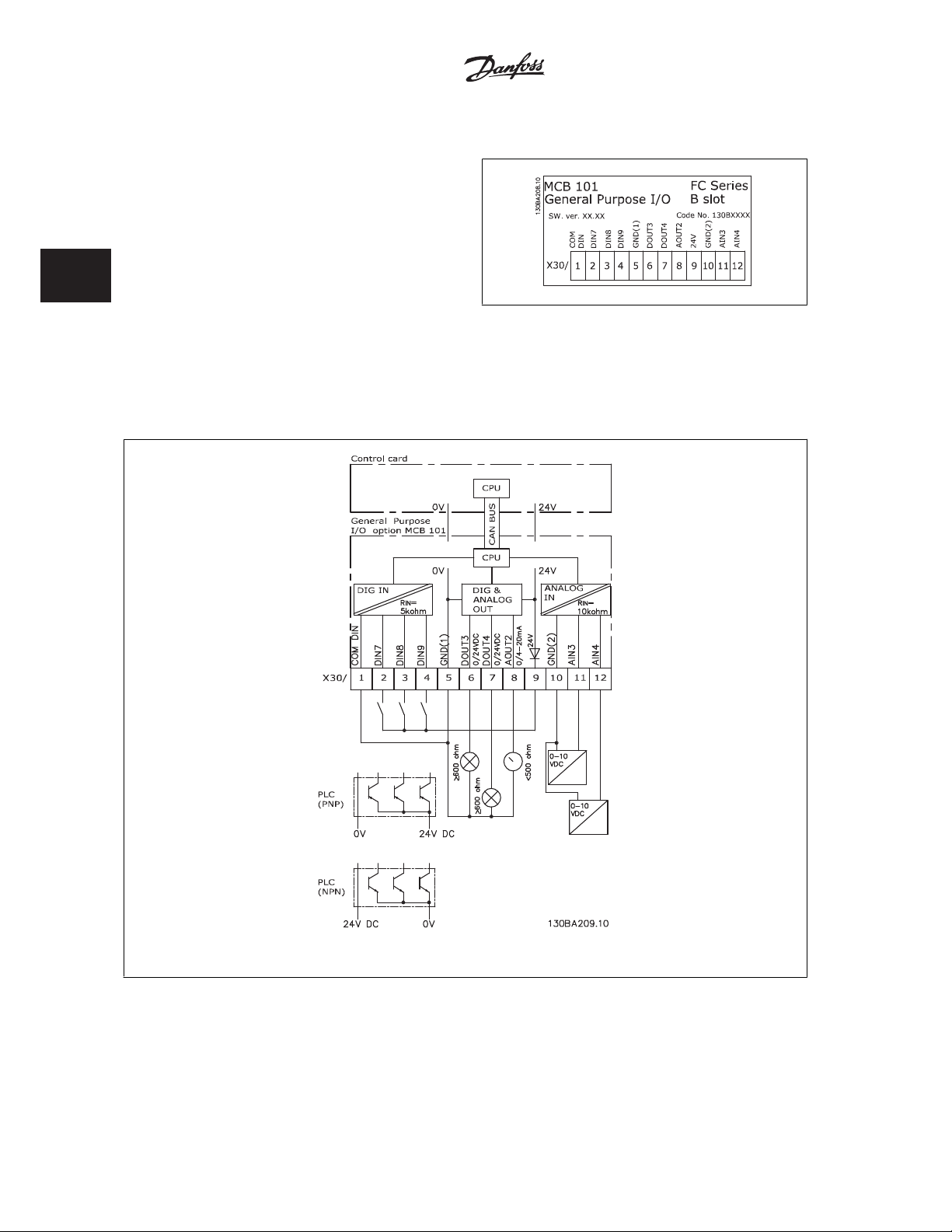
3
3 VLT Automation VT Drive Selection Automation VT Drive FC322 Design Guide
3.6.2 General Purpose Input Output Module MCB 101
MCB 101 is used for extension of the number of digital and analog inputs
and outputs of the VLT Automation VT Drive.
Contents: MCB 101 must be fitted into slot B in the VLT Auto-
mation VT Drive.
• MCB 101 option module
•Extended LCP frame
• Terminal cover
Galvanic Isolation in the MCB 101
Digital/analog inputs are galvanically isolated from other inputs/outputs on the MCB 101 and in the control card of the drive. Digital/analog outputs in
the MCB 101 are galvanically isolated from other inputs/outputs on the MCB 101, but not from these on the control card of the drive.
If the digital inputs 7, 8 or 9 are to be switched by use of the internal 24 V power supply (terminal 9) the connection between terminal 1 and 5 which is
illustrated in the drawing has to be established.
Illustration 3.20: Principle Diagram
80
MG.20.X1.22 - VLTp is a registered Danfoss trademark
Page 83

Automation VT Drive FC322 Design Guide 3 VLT Automation VT Drive Selection
3.6.3 Digital inputs - Terminal X30/1-4
Parameters for set-up: 5-16, 5-17 and 5-18
Number of digital
inputs
3 0-24 V DC PNP type:
3.6.4 Analog Voltage inputs - Terminal X30/10-12
Parameters for set-up: 6-3*, 6-4* and 16-76
Number of analog voltage inputs Standardized input signal Tolerance Resolution Max. Input impedance
2 0-10 V DC ± 20 V continuously 10 bits Approx. 5 K ohm
Voltage level Voltage levels Tolerance Max. Input impedance
Common = 0 V
Logic “0”: Input < 5 V DC
Logic “0”: Input > 10 V DC
NPN type:
Common = 24 V
Logic “0”: Input > 19 V DC
Logic “0”: Input < 14 V DC
± 28 V continuous
± 37 V in minimum 10 sec.
Approx. 5 k ohm
3
3.6.5 Digital Outputs - Terminal X30/5-7
Parameters for set-up: 5-32 and 5-33
Number of digital outputs Output level Tolerance Max.impedance
2 0 or 24 V DC ± 4 V ุ 600 ohm
3.6.6 Analog Outputs - Terminal X30/5+8
Parameters for set-up: 6-6* and 16-77
Number of analog outputs Output signal level Tolerance Max.impedance
1 0/4 - 20 mA ± 0.1 mA < 500 ohm
MG.20.X1.22 - VLTp is a registered Danfoss trademark
81
Page 84

3 VLT Automation VT Drive Selection Automation VT Drive FC322 Design Guide
3.6.7 Relay Option MCB 105
The MCB 105 option includes 3 pieces of SPDT contacts and must be fitted into option slot B.
3
Electrical Data:
Max terminal load (AC-1)
Max terminal load (AC-15 )
Max terminal load (DC-1)
Max terminal load (DC-13)
Min terminal load (DC) 5 V 10 mA
Max switching rate at rated load/min load 6 min-1/20 sec
1) IEC 947 part 4 and 5
When the relay option kit is ordered separately the kit includes:
• Relay Module MCB 105
• Extended LCP frame and enlarged terminal cover
• Label for covering access to switches S201, S202 and S801
• Cable strips for fastening cables to relay module
1)
(Resistive load) 240 V AC 2A
1)
(Inductive load @ cos 0.4) 240 V AC 0.2 A
1)
(Resistive load) 24 V DC 1 A
1)
(Inductive load) 24 V DC 0.1 A
-1
A2-A3-B3 A5-B1-B2-B4-C1-C2-C3-C4
1)
IMPORTANT! The label MUST be placed on the LCP frame as shown (UL approved).
82
MG.20.X1.22 - VLTp is a registered Danfoss trademark
Page 85

Automation VT Drive FC322 Design Guide 3 VLT Automation VT Drive Selection
3
Warning Dual supply
How to add the MCB 105 option:
• See mounting instructions in the beginning of section
• The power to the live part connections on relay terminals must be disconnected.
• Do not mix live parts (high voltage) with control signals (PELV).
• Select the relay functions in par. 5-40
NB! (Index [6] is relay 7, index [7] is relay 8, and index [8] is relay 9)
Function Relay
Options and Accessories
[6-8], par. 5-41
On Delay, Relay
[6-8] and par. 5-42
Off Delay, Relay
[6-8].
MG.20.X1.22 - VLTp is a registered Danfoss trademark
83
Page 86

3 VLT Automation VT Drive Selection Automation VT Drive FC322 Design Guide
Do not combine low voltage parts and PELV systems.
3.6.8 24 V Back-Up Option MCB 107 (Option D)
3
External 24 V DC Supply
An external 24 V DC supply can be installed for low-voltage supply to the control card and any option card installed. This enables full operation of the
LCP (including the parameter setting) and field busses without mains supplied to the power section.
External 24 V DC supply specification:
Input voltage range 24 V DC ±15 % (max. 37 V in 10 s)
Max. input current 2.2 A
Average input current for the frequency converter 0.9 A
Max cable length 75 m
Input capacitance load < 10 uF
Power-up delay < 0.6 s
The inputs are protected.
Terminal numbers:
Terminal 35: - external 24 V DC supply.
Terminal 36: + external 24 V DC supply.
Follow these steps:
1. Remove the LCP or Blind Cover
2. Remove the Terminal Cover
3. Remove the Cable De-coupling Plate and the plastic cover un-
derneath
4. Insert the 24 V DC Backup External Supply Option in the Option
Slot
5. Mount the Cable De-coupling Plate
6. Attach the Terminal Cover and the LCP or Blind Cover.
When MCB 107, 24 V backup option is supplying the control circuit, the
internal 24 V supply is automatically disconnected.
Illustration 3.21: Connection to 24 V backup supplier (A2-
A3).
84
MG.20.X1.22 - VLTp is a registered Danfoss trademark
Page 87

Automation VT Drive FC322 Design Guide 3 VLT Automation VT Drive Selection
3
Illustration 3.22: Connection to 24 V backup supplier (A5-
C2).
MG.20.X1.22 - VLTp is a registered Danfoss trademark
85
Page 88

3
3 VLT Automation VT Drive Selection Automation VT Drive FC322 Design Guide
3.6.9 Analog I/O Option MCB 109
The Analog I/O card is supposed to be used in e.g. the following cases:
• Providing battery back-up of clock function on control card
• As general extension of analog I/O selection available on control card, e.g. for multi-zone control with three pressure transmitters
• Turning frequency converter into de-central I/O block supporting Building Management System with inputs for sensors and outputs for operating
dampers and valve actuators
• Support Extended PID controllers with I/Os for set point inputs, transmitter/sensor inputs and outputs for actuators.
Illustration 3.23: Principle diagram for Analog I/O mounted in frequency converter.
Analog I/O configuration
3 x Analog Inputs, capable of handling following:
• 0 - 10 VDC
OR
• 0-20 mA (voltage input 0-10V) by mounting a 510വ resistor across terminals (see NB!)
• 4-20 mA (voltage input 2-10V) by mounting a 510വ resistor across terminals (see NB)
•
Ni1000 temperature sensor of 1000 വ at 0r C. Specifications according to DIN43760
• Pt1000 temperature sensor of 1000 വ at 0r C. Specifications according to IEC 60751
3 x Analog Outputs supplying 0-10 VDC.
86
MG.20.X1.22 - VLTp is a registered Danfoss trademark
Page 89

Automation VT Drive FC322 Design Guide 3 VLT Automation VT Drive Selection
NB!
Please note the values available within the different standard groups of resistors:
E12: Closest standard value is 470വ, creating an input of 449.9വ and 8.997V.
E24: Closest standard value is 510വ, creating an input of 486.4വ and 9.728V.
E48: Closest standard value is 511വ, creating an input of 487.3വ and 9.746V.
E96: Closest standard value is 523വ, creating an input of 498.2വ and 9.964V.
Analog inputs - terminal X42/1-6
Parameter group for read out: 18-3*. See also
Programming Guide.
3
Parameter groups for set-up: 26-0*, 26-1*, 26-2* and 26-3*. See also
3 x Analog inputs Operating range Resolution Accuracy Sampling Max load Impedance
Used as
temperature
sensor input
Used as
voltage input
When used for voltage, analog inputs are scalable by parameters for each input.
When used for temperature sensor, analog inputs scaling is preset to necessary signal level for specified temperature span.
When analog inputs are used for temperature sensors, it is possible to read out feedback value in both rC and rF.
When operating with temperature sensors, maximum cable length to connect sensors is 80 m non-screened / non-twisted wires.
Analog outputs - terminal X42/7-12
Parameter group for read out and write: 18-3*. See also
Parameter groups for set-up: 26-4*, 26-5* and 26-6*. See also
3 x Analog outputs Output signal level Resolution Linearity Max load
Volt 0-10 VDC 11 bits 1% of full scale 1 mA
-50 to +150 °C 11 bits -50 °C
0 - 10 VDC 10 bits
Programming Guide
Programming Guide.
±1 Kelvin
+150 °C
±2 Kelvin
0.2% of full
scale at cal.
temperature
Programming Guide
3 Hz - -
2.4 Hz
+/- 20 V
continuously
Approximately
5 k
Analog outputs are scalable by parameters for each output.
The function assigned is selectable via a parameter and have same options as for analog outputs on control card.
For a more detailed description of parameters, please refer to the
Real-time clock (RTC) with back-up
The data format of RTC includes year, month, date, hour, minutes and weekday.
Accuracy of clock is better than s 20 ppm at 25 rC.
The built-in lithium back-up battery lasts on average for minimum 0 years, when frequency converter is operating at 40 rC ambient temperature. If battery
pack back-up fails, analog I/O option must be exchanged.
MG.20.X1.22 - VLTp is a registered Danfoss trademark
Programming Guide
.
87
Page 90

3 VLT Automation VT Drive Selection Automation VT Drive FC322 Design Guide
3.6.10 Extended Cascade Controller MCO 101 and Advanced Cascade Controller, MCO 102
Cascade control is a common control system used to control parallel pumps or fans in an energy efficient way.
The Cascade Controller option provides the capability to control multiple pumps configured in parallel in a way that makes them appear as a single larger
pump.
3
When using Cascade Controllers, the individual pumps are automatically turned on (staged) and turned off (de-staged) as needed in order to satisfy the
required system output for flow or pressure. The speed of pumps connected to VLT Automation VT Drive is also controlled to provide a continuous range
of system output.
Illustration 3.24: Cascade control of multiple pumps
The Cascade Controllers are optional hardware and software components that can be added to the VLT Automation VT Drive. It consists of an option
board containing 3 relays that is installed in the B option location on the Drive. Once options are installed the parameters needed to support the Cascade
Controller functions will be available through the control panel in the 27-** parameter group. The Extended Cascade Controller offers more functionality
than the Basic Cascade Controller. It can be used to extend the Basic Cascade with 3 relays and even to 8 relays with the Advanced Cascade Control card
installed.
While the Cascade controller is designed for pumping applications and this document describes the cascade controller for this application, it is also possible
to use the Cascade Controllers for any application requiring multiple motors configured in parallel.
88
MG.20.X1.22 - VLTp is a registered Danfoss trademark
Page 91

Automation VT Drive FC322 Design Guide 3 VLT Automation VT Drive Selection
3.6.11 General Description
The Cascade Controller software runs from a single VLT Automation VT Drive with the Cascade Controller option card installed. This frequency converter
is referred to as the Master Drive. It controls a set of pumps each controlled by a frequency converter or connected directly to mains through a contactor
or through a soft starter.
Each additional frequency converter in the system is referred to as a Follower Drive. These frequency converters do not need the Cascade Controller
option card installed. They are operated in open loop mode and receive their speed reference from the Master Drive. The pumps connected to these
frequency converters are referred to as Variable Speed Pumps.
Each additional pump connected to mains through a contactor or through a soft starter is referred to as a Fixed Speed Pump.
Each pump, variable speed or fixed speed, is controlled by a relay in the Master Drive. The frequency converter with the Cascade Controller option card
installed has five relays available for controlling pumps. Two (2) relays are standard in the FC and additional 3 relays are found on the option card MCO
101 or 8 relays and 7 digital inputs on option card MCO 102.
The Cascade Controller is capable of controlling a mix of variable speed and fixed speed pumps. Possible configurations are described in more detail in
the next section. For simplicity of description within this manual, Pressure and Flow will be used to describe the variable output of the set of pumps
controlled by the cascade controller.
3.6.12 Extended Cascade Control MCO 101
3
The MCO 101 option includes 3 pieces of change-over contacts and can be fitted into option slot B.
Electrical Data:
Max terminal load (AC) 240 V AC 2A
Max terminal load (DC) 24 V DC 1 A
Min terminal load (DC) 5 V 10 mA
Max switching rate at rated load/min load 6 min-1/20 sec
Illustration 3.25: Mounting of B-options
-1
MG.20.X1.22 - VLTp is a registered Danfoss trademark
89
Page 92

3
3 VLT Automation VT Drive Selection Automation VT Drive FC322 Design Guide
Warning Dual supply
NB!
The label MUST be placed on the LCP frame as shown (UL approved).
How to add the MCO 101 option:
• The power to the frequency converter must be disconnected.
• The power to the live part connections on relay terminals must be disconnected.
• Remove the LCP, the terminal cover and the cradle from the FC322.
• Fit the MCO 101 option in slot B.
• Connect the control cables and relief the cables by the enclosed cable strips.
• Various systems must not be mixed.
• Fit the extended cradle and terminal cover.
•Replace the LCP
• Connect power to the frequency converter.
Wiring the Terminals
Do not combine low voltage parts and PELV systems.
90
MG.20.X1.22 - VLTp is a registered Danfoss trademark
Page 93

Automation VT Drive FC322 Design Guide 3 VLT Automation VT Drive Selection
3.6.13 Brake Resistors
In applications where the motor is used as a brake, energy is generated in the motor and send back into the frequency converter. If the energy can not
be transported back to the motor it will increase the voltage in the converter DC-line. In applications with frequent braking and/or high inertia loads this
increase may lead to an over voltage trip in the converter and finally a shut down. Brake resistors are used to dissipate the excess energy resulting from
the regenerative braking. The resistor is selected in respect to its ohmic value, its power dissipation rate and its physical size. Danfoss offers a wide variety
of different resistors that are specially designed to our frequency converters. See the section
resistors. Code numbers can be found in the section
How to order
.
Control with brake function
for the dimensioning of brake
3
MG.20.X1.22 - VLTp is a registered Danfoss trademark
91
Page 94

3 VLT Automation VT Drive Selection Automation VT Drive FC322 Design Guide
3.6.14 Remote Mounting Kit for LCP
3
The Local Control Panel can be moved to the front of a cabinet by using
the remote build in kit. The enclosure is the IP65. The fastening screws
must be tightened with a torque of max. 1 Nm.
Ordering no. 130B1113 Ordering no. 130B1114
Illustration 3.26: LCP Kit with graphical LCP, fasteners, 3 m cable and
gasket.
Technical data
Enclosure: IP 65 front
Max. cable length between and unit: 3 m
Communication std: RS 485
Illustration 3.27: LCP Kit with numerical LCP, fasternes and gasket.
LCP Kit without LCP is also available. Ordering number: 130B1117
For IP55 units the ordering number is 130B1129.
92
MG.20.X1.22 - VLTp is a registered Danfoss trademark
Page 95

Automation VT Drive FC322 Design Guide 3 VLT Automation VT Drive Selection
3.6.15 IP 21/IP 4X/ TYPE 1 Enclosure Kit
IP 20/IP 4X top/ TYPE 1 is an optional enclosure element available for IP 20 Compact units, enclosure size A2-A3 up to 7.5 kW.
If the enclosure kit is used, an IP 20 unit is upgraded to comply with enclosure IP 21/ 4X top/TYPE 1.
The IP 4X top can be applied to all standard IP 20 VLT Automation VT Drive variants.
A – Top cover
B – Brim
C – Base part
D – Base cover
E – Screw(s)
Place the top cover as
shown. If an A or B option
is used the brim must be fit-
ted to cover the top inlet.
Place the base part C at the
bottom of the drive and use
the clamps from the acces-
sory bag to correctly fasten
the cables. Holes for cable
glands:
Size A2: 2x M25 and 3xM32
Size A3: 3xM25 and 3xM32
A2 Enclosure A3 Enclosure
3
A2, A3, B3 B4, C3, C4
MG.20.X1.22 - VLTp is a registered Danfoss trademark
93
Page 96

3
3 VLT Automation VT Drive Selection Automation VT Drive FC322 Design Guide
3.6.16 Input Filters
Harmonic current distortion is caused by the 6-pulse diode rectifier of the variable speed drive. The harmonic currents are affecting the installed serial
equipment identical to reactive currents. Consequently harmonic current distortion can result in overheating of the supply transformer, cables etc. De-
pending on the impedance of the power grid, harmonic current distortion can lead to voltage distortion also affecting other equipment powered by the
same transformer. Voltage distortion is increasing losses, causes premature aging and worst of all erratic operation. The majority of harmonics are reduced
by the built-in DC coil but if additional reduction is needed, Danfoss offers two types of passive filters.
The Danfoss AHF 005 and AHF 010 are advanced harmonic filters, not to be compared with traditional harmonic trap filters. The Danfoss harmonic filters
have been specially designed to match the Danfoss frequency converters.
AHF 010 is reducing the harmonic currents to less than 10% and the AHF 005 is reducing harmonic currents to less than 5% at 2% background distortion
and 2% imbalance.
3.6.17 Output Filters
The high speed switching of the frequency converter produces some secondary effects, which influence the motor and the enclosed environment. These
side effects are addressed by two different filter types, -the du/dt and the Sine-wave filter.
du/dt filters
Motor insulation stresses are often caused by the combination of rapid voltage and current increase. The rapid energy changes can also be reflected back
to the DC-line in the inverter and cause shut down. The du/dt filter is designed to reduce the voltage rise time/the rapid energy change in the motor and
by that intervention avoid premature aging and flashover in the motor insulation. du/dt filters have a positive influence on the radiation of magnetic noise
in the cable that connects the drive to the motor. The voltage wave form is still pulse shaped but the du/dt ratio is reduced in comparison with the
installation without filter.
Sine-wave filters
Sine-wave filters are designed to let only low frequencies pass. High frequencies are consequently shunted away which results in a sinusoidal phase to
phase voltage waveform and sinusoidal current waveforms.
With the sinusoidal waveforms the use of special frequency converter motors with reinforced insulation is no longer needed. The acoustic noise from the
motor is also damped as a consequence of the wave condition.
Besides the features of the du/dt filter, the sine-wave filter also reduces insulation stress and bearing currents in the motor thus leading to prolonged
motor lifetime and longer periods between services. Sine-wave filters enable use of longer motor cables in applications where the motor is installed far
from the drive. The length is unfortunately limited because the filter does not reduce leakage currents in the cables.
94
MG.20.X1.22 - VLTp is a registered Danfoss trademark
Page 97

Automation VT Drive FC322 Design Guide 3 VLT Automation VT Drive Selection
3.7 High Power Options
3.7.1 Installation of Duct Cooling Kit in Rittal Enclosures
This section deals with the installation of IP00 / chassis enclosed frequency converters with duct work cooling kits in Rittal enclosures. In addition to the
enclosure a 200 mm base/plinth is required.
3
Illustration 3.28: Installation of IP00 in Rittal TS8 enclosure.
The minimum enclosure dimension is:
• D3 and D4 frame: Depth 500 mm and width 600 mm.
• E2 frame: Depth 600 mm and width 800 mm.
MG.20.X1.22 - VLTp is a registered Danfoss trademark
95
Page 98

3
3 VLT Automation VT Drive Selection Automation VT Drive FC322 Design Guide
The maximum depth and width are as required by the installation. When using multiple frequency converters in one enclosure it is recommended that
each drive is mounted on its own back panel and supported along the mid-section of the panel. These duct work kits do not support the “in frame”
mounting of the panel (see Rittal TS8 catalogue for details). The duct work cooling kits listed in the table below are suitable for use only with IP 00 /
Chassis frequency converters in Rittal TS8 IP 20 and UL and NEMA 1 and IP 54 and UL and NEMA 12 enclosures.
For the E2 frames it is important to mount the plate at the absolute rear of the Rittal enclosure due to the weight of the frequency
converter.
NB!
A door-fan(s) is required on the Rittal cabinet to remove the loses not contained in the back-channel of the drive. The minimum door-
fan(s) airflow required at the drive maximum ambient for the D3 and D4 is 391 m^3/h (230 cfm). The minimum door-fan(s) airflow
required at the drive maximum ambient for the E2 is 782 m^3/h (460 cfm). If the ambient is below maximum or if additional compo-
nents, heat loses, are added within the enclosure a calculation must be made to ensure the proper airflow is provided to cool the inside
of the Rittal enclosure.
Ordering Information
Rittal TS-8 Enclosure Frame D3 Kit Part No. Frame D4Kit Part No. Frame E2 Part No.
1800 mm 176F1824 176F1823 Not possible
2000 mm 176F1826 176F1825 176F1850
2200 mm 176F0299
Kit Contents
• Ductwork components
• Mounting hardware
•Gasket material
• Delivered with D3 and D4 frame kits:
• 175R5639 - Mounting templates and top/bottom cut out for Rittal enclosure.
• Delivered with E2 frame kits:
• 175R1036 - Mounting templates and top/bottom cut out for Rittal enclosure.
All fasteners are either:
• 10 mm, M5 Nuts torque to 2.3 Nm (20 in-lbs)
• T25 Torx screws torque to 2.3 Nm (20 in-lbs)
NB!
Please see the
External ducts
If additional duct work is added externally to the Rittal cabinet the pressure drop in the ducting must be calculated. Use the charts below to derate the
frequency converter according to the pressure drop.
Duct Kit Instruction Manual, 175R5640,
for further information
96
MG.20.X1.22 - VLTp is a registered Danfoss trademark
Page 99

Automation VT Drive FC322 Design Guide 3 VLT Automation VT Drive Selection
3
Illustration 3.29: D Frame Derating vs. Pressure Change
Drive air flow: 450 cfm (765 m3/h)
Illustration 3.30: E Frame Derating vs. Pressure Change (Small Fan), P250T5 and P355T7-P400T7
Drive air flow: 650 cfm (1105 m3/h)
Illustration 3.31: E Frame Derating vs. Pressure Change (Large Fan), P315T5-P400T5 and P500T7-P560T7
Drive air flow: 850 cfm (1445 m3/h)
MG.20.X1.22 - VLTp is a registered Danfoss trademark
97
Page 100

3
3 VLT Automation VT Drive Selection Automation VT Drive FC322 Design Guide
3.7.2 Outside Installation/ NEMA 3R Kit for Rittal Enclosures
This section is for the installation of NEMA 3R kits available for the frequency converter frames D3, D4 and E2. These kits are designed and tested to be
used with IP00/ Chassis versions of these frames in Rittal TS8 NEMA 3R or NEMA 4 enclosures. The NEMA-3R enclosure is an outdoor enclosure that
provides a degree of protection against rain and ice. The NEMA-4 enclosure is an outdoor enclosure that provides a greater degree of protection against
weather and hosed water.
The minimum enclosure depth is 500 mm (600 mm for E2 frame) and the kit is designed for a 600 mm (800 mm for E2 frame) wide enclosure. Other
enclosure widths are possible, however additional Rittal hardware is required. The maximum depth and width are as required by the installation.
NB!
The current rating of drives in D3 and D4 frames are de-rated by 3%, when adding the NEMA 3R kit. Drives in E2 frames require no
derating
NB!
A door-fan(s) is required on the Rittal cabinet to remove the loses not contained in the back-channel of the drive. The minimum door-
fan(s) airflow required at the drive maximum ambient for the D3 and D4 is 391 m^3/h (230 cfm). The minimum door-fan(s) airflow
required at the drive maximum ambient for the E2 is 782 m^3/h (460 cfm). If the ambient is below maximum or if additional compo-
nents, heat loses, are added within the enclosure a calculation must be made to ensure the proper airflow is provided to cool the inside
of the Rittal enclosure.
98
MG.20.X1.22 - VLTp is a registered Danfoss trademark
 Loading...