

Page 1
MAKING MODERN LIVING POSSIBLE
Design Guide
VLT® AutomationDrive
Page 2

Contents FC 300 Design Guide
Contents
1 How to Read this Design Guide
1.1.1 Symbols 7
1.1.2 Abbreviations 7
1.1.3 Definitions 8
2 Safety and Conformity
2.1 Safety Precautions
3 Introduction to FC 300
3.1 Product Overview
3.2.1 Control Principle 17
3.2.2 FC 300 Controls 17
3.2.3 FC 301 vs. FC 302 Control Principle 18
3.2.4 Control Structure in VVC
3.2.5 Control Structure in Flux Sensorless (FC 302 only) 20
3.2.6 Control Structure in Flux with Motor Feedback 21
3.2.7 Internal Current Control in VVC
3.2.8 Local (Hand On) and Remote (Auto On) Control 22
plus
Advanced Vector Control 19
plus
Mode 22
7
11
11
15
15
3.3 Reference Handling
3.3.1 Reference Limits 24
3.3.2 Scaling of Preset References and Bus References 25
3.3.3 Scaling of Analog and Pulse References and Feedback 25
3.3.4 Dead Band Around Zero 26
3.4 PID Control
3.4.1 Speed PID Control 30
3.4.2 Tuning PID Speed Control 31
3.4.3 Process PID Control 32
3.4.4 Example of Process PID Control 34
3.4.5 Ziegler Nichols Tuning Method 35
3.5 General Aspects of EMC
3.5.1 General Aspects of EMC Emissions 37
3.5.2 EMC Test Results 38
3.5.3 Emission Requirements 39
3.5.4 Immunity Requirements 40
3.6.1 PELV - Protective Extra Low Voltage 41
23
30
37
3.8 Brake Functions in FC 300
3.8.1 Mechanical Holding Brake 42
3.8.2 Dynamic Braking 43
3.8.3 Selection of Brake Resistor 43
MG.33.BD.02 - VLT® is a registered Danfoss trademark 1
42
Page 3

Contents FC 300 Design Guide
3.9.1 Mechanical Brake Control 45
3.9.2 Hoist Mechanical Brake 46
3.9.3 Brake Resistor Cabling 47
3.10 Smart Logic Controller
3.11 Extreme Running Conditions
3.11.1 Motor Thermal Protection 49
3.12 Safe Stop of FC 300
3.12.2 Installation of External Safety Device in Combination with MCB 112 56
3.12.3 Safe Stop Commissioning Test 57
3.13 Certificates
4 FC 300 Selection
4.1 Electrical Data - 200-240V
4.2 Electrical Data - 380-500V
4.3 Electrical Data - 525-600V
4.4 Electrical Data - 525-690V
4.5 General Specifications
4.7.1 Acoustic Noise 90
4.8.1 du/dt Conditions 91
4.9 Special Conditions
4.9.1 Manual Derating 94
47
49
51
58
60
60
63
71
74
85
94
4.6.1.1 Derating for Running at Low Speed 94
4.9.2 Automatic Derating 94
5 How to Order
5.1.1 Ordering from Type Code 95
5.1.2 Drive Configurator 95
5.2.1 Ordering Numbers: Options and Accessories 99
5.2.2 Ordering Numbers: Spare Parts 100
5.2.3 Ordering Numbers: Accessory Bags 100
5.2.4 Ordering Numbers: High Power Kits 101
5.2.5 Ordering Numbers: Brake Resistors 10% 101
5.2.6 Ordering Numbers: Brake Resistors 40% 106
5.2.7 Flat Packs 111
5.2.8 Ordering Numbers: Harmonic Filters 113
5.2.9 Ordering Numbers: Sine Wave Filter Modules, 200-500 VAC 115
5.2.10 Ordering Numbers: Sine-Wave Filter Modules, 525-690 VAC 116
5.2.11 Ordering Numbers: du/dt Filters, 380-480/500V AC 116
5.2.12 Ordering Numbers: du/dt Filters, 525-690V AC 116
95
6 Mechanical Installation - Frame Size A, B and C
2 MG.33.BD.02 - VLT® is a registered Danfoss trademark
117
Page 4

Contents FC 300 Design Guide
6.1.1 Safety Requirements of Mechanical Installation 117
6.1.2 Mechanical Mounting 120
7 Mechanical Installation - Frame size D, E and F
7.1 Pre-installation
7.1.1 Planning the Installation Site 121
7.1.2 Receiving the Frequency Converter 121
7.1.3 Transportation and Unpacking 121
7.1.4 Lifting 121
7.1.5 Mechanical Dimensions 123
7.1.6 Mechanical Dimensions, 12-Pulse Units 130
7.2 Mechanical Installation
7.2.1 Tools Needed 133
7.2.2 General Considerations 133
7.2.3 Terminal Locations - Frame size D 135
7.2.4 Terminal Locations - Frame size E 137
7.2.5 Terminal Locations - Frame size F 142
7.2.6 Terminal Locations, F8-F13 - 12-Pulse 146
7.2.7 Cooling and Airflow 151
7.2.8 Installation on the Wall - IP21 (NEMA 1) and IP54 (NEMA 12) Units 152
121
121
133
7.2.9 Gland/Conduit Entry - IP21 (NEMA 1) and IP54 (NEMA12) 153
7.2.10 Gland/Conduit Entry, 12-Pulse - IP21 (NEMA 1) and IP54 (NEMA12) 154
7.2.11 IP21 Drip Shield Installation (Frame size D1 and D2 ) 156
8 Electrical Installation
8.1 Connections- Frame Sizes A, B and C
8.1.1 Removal of Knockouts for Extra Cables 158
8.1.2 Connection to Mains and Earthing 158
8.1.3 Motor Connection 160
8.1.4 Relay Connection 168
8.2 Connections - Frame Sizes D, E and F
8.2.1 Torque 169
8.2.2 Power Connections 169
8.2.3 Power Connections 12-Pulse Drives 180
8.2.4 Shielding against Electrical Noise 189
8.2.5 External Fan Supply 189
8.3 Fuses and Circuit Breakers
8.3.1 Recommendations 190
157
157
169
190
8.3.2 CE Compliance 191
8.4 Disconnectors and Contactors
8.4.1 Mains Disconnectors 203
MG.33.BD.02 - VLT® is a registered Danfoss trademark 3
203
Page 5

Contents FC 300 Design Guide
8.4.4 F-Frame Mains Contactors 205
8.5 Additional Motor Information
8.5.1 Motor Cable 206
8.5.2 Motor Thermal Protection 206
8.5.3 Parallel Connection of Motors 206
8.5.5 Motor Bearing Currents 208
8.6 Control Cables and Terminals
8.6.1 Access to Control Terminals 209
8.6.2 Control Cable Routing 209
8.6.3 Control Terminals 210
8.6.4 Switches S201, S202, and S801 211
8.6.5 Electrical Installation, Control Terminals 211
8.6.6 Basic Wiring Example 212
8.6.7 Electrical Installation, Control Cables 213
8.6.8 12-Pulse Control Cables 215
8.6.9 Relay Output 218
8.6.10 Brake Resistor Temperature Switch 218
8.7 Additional Connections
206
209
218
8.7.1 DC Bus Connection 218
8.7.2 Load Sharing 218
8.7.3 Installation of Brake Cable 219
8.7.4 How to Connect a PC to the Frequency Converter 219
8.7.5 The FC 300 PC Software 219
8.8.1 High Voltage Test 220
8.8.2 Earthing 220
8.8.3 Safety Earth Connection 220
8.9 EMC-correct Installation
8.9.1 Electrical Installation - EMC Precautions 220
8.9.2 Use of EMC-Correct Cables 222
8.9.3 Earthing of Screened Control Cables 224
8.9.4 RFI Switch 224
8.10.1 Mains Supply Interference/Harmonics 225
8.10.2 The Effect of Harmonics in a Power Distribution System 225
8.10.3 Harmonic Limitation Standards and Requirements 226
8.10.4 Harmonic Mitigation 226
220
8.10.5 Harmonic Calculation 226
8.11 Residual Current Device - FC 300 DG
8.12 Final Setup and Test
9 Application Examples
9.1.1 Encoder Connection 233
4 MG.33.BD.02 - VLT® is a registered Danfoss trademark
226
227
228
Page 6

Contents FC 300 Design Guide
9.1.2 Encoder Direction 233
9.1.3 Closed Loop Drive System 233
9.1.4 Programming of Torque Limit and Stop 233
10 Options and Accessories
10.1.1 Mounting of Option Modules in
Slot A 235
10.1.2 Mounting of Option Modules in
Slot B 235
10.1.3 Mounting of Options in Slot C 236
10.2 General Purpose Input Output Module MCB 101
10.2.1 Galvanic Isolation in the MCB 101 236
10.2.2 Digital Inputs - Terminal X30/1-4: 238
10.2.3 Analog Inputs - Terminal X30/11, 12: 238
10.2.4 Digital Outputs - Terminal X30/6, 7: 238
10.2.5 Analog Output - Terminal X30/8: 238
10.3 Encoder Option MCB 102
10.4 Resolver Option MCB 103
10.5 Relay Option MCB 105
10.6 24V Back-Up Option MCB 107
10.7 MCB 112 PTC Thermistor Card
10.8 MCB 113 Extended Relay Card
235
236
239
240
241
243
244
246
10.9 Brake Resistors
10.10 LCP Panel Mounting Kit
10.11 IP21/IP 4X/ TYPE 1 Enclosure Kit
10.12 Mounting Bracket for Frame Size A5, B1, B2, C1 and C2
10.13 Sine-wave Filters
10.14 High Power Options
10.14.1 Frame Size F Options 253
11 RS-485 Installation and Set-up
11.1 Overview
11.2 Network Connection
11.3 Bus Termination
11.4.1 EMC Precautions 256
11.5 Network Configuration
11.5.1 FC 300 Frequency Converter Set-up 256
11.6 FC Protocol Message Framing Structure - FC 300
11.6.1 Content of a Character (byte) 257
11.6.2 Telegram Structure 257
247
247
248
251
253
253
255
255
255
255
256
257
11.6.3 Length (LGE) 257
11.6.4 Frequency Converter Address (ADR) 257
MG.33.BD.02 - VLT® is a registered Danfoss trademark 5
Page 7

Contents FC 300 Design Guide
11.6.5 Data Control Byte (BCC) 257
11.6.6 The Data Field 257
11.6.7 The PKE Field 258
11.6.8 Parameter Number (PNU) 259
11.6.9 Index (IND) 259
11.6.10 Parameter Value (PWE) 259
11.6.11 Data Types Supported by FC 300 260
11.6.12 Conversion 260
11.6.13 Process Words (PCD) 261
11.7 Examples
11.7.1 Writing a Parameter Value 261
11.7.2 Reading a Parameter Value 261
11.8 Modbus RTU Overview
11.8.1 Assumptions 261
11.8.2 What the User Should Already Know 261
11.8.3 Modbus RTU Overview 261
11.8.4 Frequency Converter with Modbus RTU 262
11.9.1 Frequency Converter with Modbus RTU 262
11.10 Modbus RTU Message Framing Structure
11.10.1 Frequency Converter with Modbus RTU 262
11.10.2 Modbus RTU Message Structure 262
11.10.3 Start/Stop Field 263
11.10.4 Address Field 263
11.10.5 Function Field 263
11.10.6 Data Field 263
11.10.7 CRC Check Field 263
261
261
262
11.10.8 Coil Register Addressing 264
11.10.9 How to Control the Frequency Converter 266
11.10.10 Function Codes Supported by Modbus RTU 266
11.10.11 Modbus Exception Codes 266
11.11 How to Access Parameters
11.11.1 Parameter Handling 266
11.11.2 Storage of Data 266
11.11.3 IND 266
11.11.4 Text Blocks 266
11.11.5 Conversion Factor 267
11.11.6 Parameter Values 267
11.12 Danfoss FC Control Profile
Index
6 MG.33.BD.02 - VLT® is a registered Danfoss trademark
266
267
275
Page 8
How to Read this Design Gui... FC 300 Design Guide
1 How to Read this Design Guide
This Design Guide will introduce all aspects of your FC 300.
Available literature for FC 300
- The VLT AutomationDrive Operating Instructions
MG.33.AX.YY provide the neccessary information
for getting the drive up and running.
- The VLT AutomationDrive High Power Operating
Instructions MG.33.UX.YY
- The VLT AutomationDrive Design Guide MG.
33.BX.YY entails all technical information about
the drive and customer design and applications.
- The VLT AutomationDrive Programming Guide
MG.33.MX.YY provides information on how to
programme and includes complete parameter
descriptions.
- The VLT AutomationDrive Profibus Operating
Instructions MG.33.CX.YY provide the information
required for controlling, monitoring and
programming the drive via a Profibus fieldbus.
- The VLT AutomationDrive DeviceNet Operating
Instructions MG.33.DX.YY provide the information
required for controlling, monitoring and
programming the drive via a DeviceNet fieldbus.
X = Revision number
YY = Language code
Danfoss Drives technical literature is also available online
at www.danfoss.com/BusinessAreas/DrivesSolutions/
Documentations/Technical+Documentation.
Symbols
1.1.1
Symbols used in this guide.
NOTE
Indicates something to be noted by the reader.
CAUTION
Indicates a potentially hazardous situation which, if not
avoided, may result in minor or moderate injury or
equipment damage.
WARNING
Indicates a potentially hazardous situation which, if not
avoided, could result in death or serious injury.
Indicates default setting
*
1.1.2 Abbreviations
Alternating current AC
American wire gauge AWG
Ampere/AMP A
Automatic Motor Adaptation AMA
Current limit I
Degrees Celsius
Direct current DC
Drive Dependent D-TYPE
Electro Magnetic Compatibility EMC
Electronic Thermal Relay ETR
frequency converter FC
Gram g
Hertz Hz
Horsepower hp
Kilohertz kHz
Local Control Panel LCP
Meter m
Millihenry Inductance mH
Milliampere mA
Millisecond ms
Minute min
Motion Control Tool MCT
Nanofarad nF
Newton Meters Nm
Nominal motor current I
Nominal motor frequency f
Nominal motor power P
Nominal motor voltage U
Parameter par.
Protective Extra Low Voltage PELV
Printed Circuit Board PCB
Rated Inverter Output Current I
Revolutions Per Minute RPM
Regenerative terminals Regen
Second sec.
Synchronous Motor Speed n
Torque limit T
Volts V
The maximum output current I
The rated output current supplied by the
frequency converter
LIM
°C
M,N
M,N
M,N
M,N
INV
s
LIM
VLT,MAX
I
VLT,N
1 1
MG.33.BD.02 - VLT® is a registered Danfoss trademark 7
Page 9
175ZA078.10
Pull-out
rpm
Torque
How to Read this Design Gui... FC 300 Design Guide
11
1.1.3 Definitions
Frequency converter:
Coast
P
M,N
The rated motor power (nameplate data).
The motor shaft is in free mode. No torque on motor.
T
I
MAX
The maximum output current.
I
N
The rated output current supplied by the frequency
converter.
U
MAX
The maximum output voltage.
M,N
The rated torque (motor).
U
M
The instantaneous motor voltage.
U
M,N
The rated motor voltage (nameplate data).
Input:
Control command
Break-away torque
Start and stop the connected motor by means of LCP and
the digital inputs.
Functions are divided into two groups.
Functions in group 1 have higher priority than functions in
group 2.
Group 1 Reset, Coasting stop, Reset and Coasting stop,
Group 2 Start, Pulse start, Reversing, Start reversing, Jog
Quick-stop, DC braking, Stop and the "Off" key.
and Freeze output
Motor:
f
JOG
The motor frequency when the jog function is activated
(via digital terminals).
f
M
Motor frequency. Output from the frequency converter.
Output frequency is related to the shaft speed on motor
depending on number of poles and slip frequency.
f
MAX
The maximum output frequency the frequency converter
applies on its output. The maximum output frequency is
set in limit par. 4-12, 4-13 and 4-19.
f
MIN
The minimum motor frequency from frequency converter.
Default 0 Hz.
f
M,N
The rated motor frequency (nameplate data).
I
M
The motor current.
I
M,N
The rated motor current (nameplate data).
n
M,N
The rated motor speed (nameplate data).
n
s
Synchronous motor speed
2 ×
par
n
=
s
. 1 − 23 × 60
par
. 1 − 39
s
η
The efficiency of the frequency converter is defined as the
ratio between the power output and the power input.
Start-disable command
A stop command belonging to the group 1 control
commands - see this group.
Stop command
See Control commands.
References:
Analog Reference
An analog signal applied to input 53 or 54. The signal can
be either Voltage 0-10V (FC 301 and FC 302) or -10 -+10V
(FC 302). Current signal 0-20 mA or 4-20 mA.
Binary Reference
A signal applied to the serial communication port (RS-485
term 68 – 69).
Preset Reference
A defined preset reference to be set from -100% to +100%
of the reference range. Selection of eight preset references
via the digital terminals.
8 MG.33.BD.02 - VLT® is a registered Danfoss trademark
Page 10

How to Read this Design Gui... FC 300 Design Guide
Pulse Reference
A pulse reference applied to term 29 or 33, selected by
par. 5-13 or 5-15 [32]. Scaling in par. group 5-5*.
Ref
MAX
Determines the relationship between the reference input
at 100% full scale value (typically 10V, 20mA) and the
resulting reference. The maximum reference value set in
3-03 Maximum Reference.
Ref
MIN
Determines the relationship between the reference input
at 0% value (typically 0V, 0mA, 4mA) and the resulting
reference. The minimum reference value set in
3-02 Minimum Reference.
Miscellaneous:
Analog Inputs
The analog inputs are used for controlling various
functions of the frequency converter.
There are two types of analog inputs:
Current input, 0-20mA and 4-20mA
Voltage input, 0-10V DC (FC 301)
Voltage input, -10 - +10V DC (FC 302).
Analog Outputs
The analog outputs can supply a signal of 0-20mA,
4-20mA.
Automatic Motor Adaptation, AMA
AMA algorithm determines the electrical parameters for
the connected motor at standstill.
Brake Resistor
The brake resistor is a module capable of absorbing the
brake power generated in regenerative braking. This
regenerative braking power increases the intermediate
circuit voltage and a brake chopper ensures that the
power is transmitted to the brake resistor.
CT Characteristics
Constant torque characteristics used for all applications
such as conveyor belts, displacement pumps and cranes.
Digital Inputs
The digital inputs can be used for controlling various
functions of the frequency converter.
Digital Outputs
The frequency converter features two Solid State outputs
that can supply a 24V DC (max. 40mA) signal.
DSP
Digital Signal Processor.
ETR
Electronic Thermal Relay is a thermal load calculation
based on present load and time. Its purpose is to estimate
the motor temperature.
Hiperface
Hiperface® is a registered trademark by Stegmann.
Initialising
If initialising is carried out (14-22 Operation Mode), the
frequency converter returns to the default setting.
®
Intermittent Duty Cycle
An intermittent duty rating refers to a sequence of duty
cycles. Each cycle consists of an on-load and an off-load
period. The operation can be either periodic duty or non-
periodic duty.
LCP
The Local Control Panel makes up a complete interface for
control and programming of the frequency converter. The
control panel is detachable and can be installed up to 3
metres from the frequency converter, i.e. in a front panel
by means of the installation kit option.
NLCP
Numerical Local Control Panel interface for control and
programming of frequency converter. The display is
numerical and the panel is basically used for display
process values. The NLCP has no storing and copy
function.
lsb
Least significant bit.
msb
Most significant bit.
MCM
Short for Mille Circular Mil, an American measuring unit for
cable cross-section. 1 MCM = 0.5067 mm2.
On-line/Off-line Parameters
Changes to on-line parameters are activated immediately
after the data value is changed. Changes to off-line
parameters are not activated until you enter [OK] on the
LCP.
Process PID
The PID regulator maintains the desired speed, pressure,
temperature, etc. by adjusting the output frequency to
match the varying load.
PCD
Process Data
Pulse Input/Incremental Encoder
An external digital sensor used for feedback information of
motor speed and direction. Encoders are used for high
speed accuracy feedback and in high dynamic applications.
The encoder connection is either via term 32 and 32 or
encoder option MCB 102.
RCD
Residual Current Device.
Set-up
You can save parameter settings in four Set-ups. Change
between the four parameter Set-ups and edit one Set-up,
while another Set-up is active.
SFAVM
Switching pattern called Stator Flux oriented Asynchronous
Vector Modulation (14-00 Switching Pattern).
Slip Compensation
The frequency converter compensates for the motor slip
by giving the frequency a supplement that follows the
1 1
MG.33.BD.02 - VLT® is a registered Danfoss trademark 9
Page 11

How to Read this Design Gui... FC 300 Design Guide
11
measured motor load keeping the motor speed almost
constant.
Smart Logic Control (SLC)
The SLC is a sequence of user defined actions executed
when the associated user defined events are evaluated as
true by the Smart Logic Controller. (Par. group 13-** Smart
Power Factor
The power factor is the relation between I1 and I
3 x U x
I
cos
ϕ
Power factor
=
3 x U x
1
I
RMS
The power factor for 3-phase control:
RMS
.
Logic Control (SLC).
STW
Status Word
FC Standard Bus
Includes RS -485 bus with FC protocol or MC protocol. See
8-30 Protocol.
I1 x cos
=
I
RMS
The power factor indicates to which extent the frequency
converter imposes a load on the mains supply.
The lower the power factor, the higher the I
same kW performance.
ϕ1
=
I
RMS
I
1
since cos
ϕ1 = 1
RMS
for the
Thermistor:
A temperature-dependent resistor placed where the
temperature is to be monitored (frequency converter or
motor).
THD
Total Harmonic Distortion state the total contribution of
harmonic.
I
RMS
=
I
+
1
2
I
+
I
+ .. +
5
7
In addition, a high power factor indicates that the different
harmonic currents are low.
All Danfoss frequency converters have built-in DC coils in
the DC link to have a high power factor and to reduce the
THD on the main supply.
2
I
n
2
2
Trip
A state entered in fault situations, e.g. if the frequency
converter is subject to an over-temperature or when the
frequency converter is protecting the motor, process or
mechanism. Restart is prevented until the cause of the
fault has disappeared and the trip state is cancelled by
activating reset or, in some cases, by being programmed
to reset automatically. Trip may not be used for personal
safety.
Trip Locked
A state entered in fault situations when the frequency
converter is protecting itself and requiring physical
intervention, e.g. if the frequency converter is subject to a
short circuit on the output. A locked trip can only be
cancelled by cutting off mains, removing the cause of the
fault, and reconnecting the frequency converter. Restart is
prevented until the trip state is cancelled by activating
reset or, in some cases, by being programmed to reset
automatically. Trip may not be used for personal safety.
VT Characteristics
Variable torque characteristics used for pumps and fans.
plus
VVC
If compared with standard voltage/frequency ratio control,
Voltage Vector Control (VVC
plus
) improves the dynamics
and the stability, both when the speed reference is
changed and in relation to the load torque.
60° AVM
Switching pattern called 60°Asynchronous Vector
Modulation (14-00 Switching Pattern).
10 MG.33.BD.02 - VLT® is a registered Danfoss trademark
Page 12

Safety and Conformity FC 300 Design Guide
2 Safety and Conformity
2.1 Safety Precautions
WARNING
The voltage of the frequency converter is dangerous
whenever connected to mains. Incorrect installation of the
motor, frequency converter or fieldbus may cause death,
serious personal injury or damage to the equipment.
Consequently, the instructions in this manual, as well as
national and local rules and safety regulations, must be
complied with.
Safety Regulations
1. The mains supply to the frequency converter
must be disconnected whenever repair work is to
be carried out. Check that the mains supply has
been disconnected and that the necessary time
has elapsed before removing motor and mains
supply plugs.
2. The [OFF] button on the control panel of the
frequency converter does not disconnect the
mains supply and consequently it must not be
used as a safety switch.
3. The equipment must be properly earthed, the
user must be protected against supply voltage
and the motor must be protected against
overload in accordance with applicable national
and local regulations.
4. The earth leakage current exceeds 3.5mA.
5. Protection against motor overload is not included
in the factory setting. If this function is desired,
set 1-90 Motor Thermal Protection to data value
ETR trip 1 [4] or data value ETR warning 1 [3].
6. Do not remove the plugs for the motor and
mains supply while the frequency converter is
connected to mains. Check that the mains supply
has been disconnected and that the necessary
time has elapsed before removing motor and
mains plugs.
7. Please note that the frequency converter has
more voltage sources than L1, L2 and L3, when
load sharing (linking of DC intermediate circuit)
or external 24V DC are installed. Check that all
voltage sources have been disconnected and that
the necessary time has elapsed before
commencing repair work.
Warning against unintended start
1. The motor can be brought to a stop by means of
digital commands, bus commands, references or
a local stop, while the frequency converter is
2 2
connected to mains. If personal safety considerations (e.g. risk of personal injury caused by
contact with moving machine parts following an
unintentional start) make it necessary to ensure
that no unintended start occurs, these stop
functions are not sufficient. In such cases the
mains supply must be disconnected or the Safe
Stop function must be activated.
2. The motor may start while setting the
parameters. If this means that personal safety
may be compromised (e.g. personal injury caused
by contact with moving machine parts), motor
starting must be prevented, for instance by use
of the Safe Stop function or secure disconnection
of the motor connection.
3. A motor that has been stopped with the mains
supply connected, may start if faults occur in the
electronics of the frequency converter, through
temporary overload or if a fault in the power
supply grid or motor connection is remedied. If
unintended start must be prevented for personal
safety reasons (e.g. risk of injury caused by
contact with moving machine parts), the normal
stop functions of the frequency converter are not
sufficient. In such cases the mains supply must be
disconnected or the Safe Stop function must be
activated.
NOTE
When using the Safe Stop function, always follow the
instructions in the section Safe Stop of the VLT
AutomationDrive Design Guide.
4. Control signals from, or internally within, the
frequency converter may in rare cases be
activated in error, be delayed or fail to occur
entirely. When used in situations where safety is
critical, e.g. when controlling the electromagnetic
brake function of a hoist application, these
control signals must not be relied on exclusively.
MG.33.BD.02 - VLT® is a registered Danfoss trademark 11
Page 13
Safety and Conformity FC 300 Design Guide
WARNING
High Voltage
22
Touching the electrical parts may be fatal - even after the
equipment has been disconnected from mains.
Also make sure that other voltage inputs have been
disconnected, such as external 24V DC, load sharing
(linkage of DC intermediate circuit), as well as the motor
connection for kinetic back up.
Systems where frequency converters are installed must, if
necessary, be equipped with additional monitoring and
protective devices according to the valid safety regulations,
e.g law on mechanical tools, regulations for the prevention
of accidents etc. Modifications on the frequency converters
by means of the operating software are allowed.
NOTE
Hazardous situations shall be identified by the machine
builder/ integrator who is responsible for taking necessary
preventive means into consideration. Additional
monitoring and protective devices may be included, always
according to valid national safety regulations, e.g. law on
mechanical tools, regulations for the prevention of
accidents.
NOTE
Crane, Lifts and Hoists:
The controlling of external brakes must always have a
redundant system. The frequency converter can in no
circumstances be the primary safety circuit. Comply with
relevant standards, e.g.
Hoists and cranes: IEC 60204-32
Lifts: EN 81
The DC link capacitors remain charged after power has
been disconnected. Be aware that there may be high
voltage on the DC link even when the Control Card LEDs
are turned off. A red LED is mounted on a circuit board
inside the drive to indicate the DC bus voltage. The red
LED will stay lit until the DC link is 50 Vdc or lower. To
avoid electrical shock hazard, disconnect the frequency
converter from mains before carrying out maintenance.
When using a PM-motor, make sure it is disconnected.
Before doing service on the frequency converter wait at
least the amount of time indicated below:
Voltage Power Waiting Time
380 - 500 V 0.25 - 7.5 kW 4 minutes
11 - 75 kW 15 minutes
90 - 200 kW 20 minutes
250 - 800 kW 40 minutes
525 - 690 V 11-75 kW (frame
size B and C)
37 - 315 kW (frame
size D)
355 - 1000 kW 30 minutes
15 minutes
20 minutes
2.2.1 Disposal Instruction
Equipment containing electrical
components may not be disposed of
together with domestic waste.
It must be separately collected with
electrical and electronic waste according
to local and currently valid legislation.
FC 300
Design Guide
Software version: 6.4x
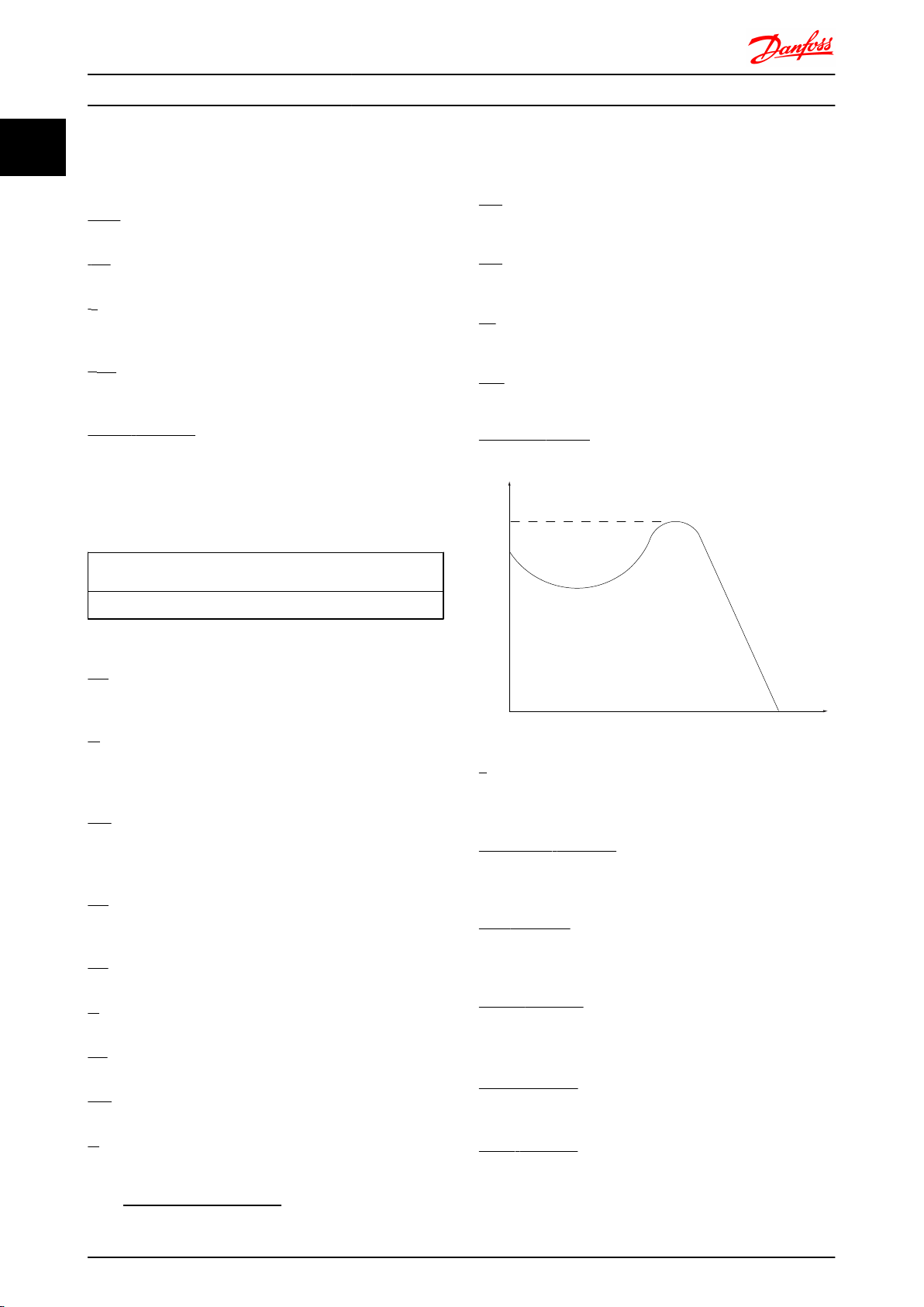
Protection Mode
Once a hardware limit on motor current or dc-link voltage
is exceeded the frequency converter will enter “Protection
mode”. “Protection mode” means a change of the PWM
modulation strategy and a low switching frequency to
minimize losses. This continues 10 sec after the last fault
and increases the reliability and the robustness of the
frequency converter while re-establishing full control of the
motor.
In hoist applications “Protection mode” is not usable
because the frequency converter will usually not be able to
leave this mode again and therefore it will extend the time
before activating the brake – which is not recommendable.
The “Protection mode” can be disabled by setting
14-26 Trip Delay at Inverter Fault to zero which means that
the frequency converter will trip immediately if one of the
hardware limits is exceeded.
NOTE
It is recommended to disable protection mode in hoisting
applications (14-26 Trip Delay at Inverter Fault = 0)
This Design Guide can be used for all FC 300 frequency
converters with software version 6.4x.
The software version number can be seen from 15-43 Software
Version.
2.3.1 CE Conformity and Labelling
The machinery directive (2006/42/EC)
Frequency converters do not fall under the machinery
directive. However, if a frequency converter is supplied for
use in a machine, we provide information on safety
aspects relating to the frequency converter.
What is CE Conformity and Labelling?
The purpose of CE labelling is to avoid technical trade
obstacles within EFTA and the EU. The EU has introduced
the CE label as a simple way of showing whether a
product complies with the relevant EU directives. The CE
label says nothing about the specifications or quality of
12 MG.33.BD.02 - VLT® is a registered Danfoss trademark
Page 14

Safety and Conformity FC 300 Design Guide
the product. Frequency converters are regulated by two EU
directives:
The low-voltage directive (2006/95/EC)
Frequency converters must be CE labelled in accordance
with the low-voltage directive of January 1, 1997. The
directive applies to all electrical equipment and appliances
used in the 50 - 1000V AC and the 75 - 1500V DC voltage
ranges. Danfoss CE-labels in accordance with the directive
and issues a declaration of conformity upon request.
The EMC directive (2004/108/EC)
EMC is short for electromagnetic compatibility. The
presence of electromagnetic compatibility means that the
mutual interference between different components/
appliances does not affect the way the appliances work.
The EMC directive came into effect January 1, 1996.
Danfoss CE-labels in accordance with the directive and
issues a declaration of conformity upon request. To carry
out EMC-correct installation, see the instructions in this
Design Guide. In addition, we specify which standards our
products comply with. We offer the filters presented in the
specifications and provide other types of assistance to
ensure the optimum EMC result.
The frequency converter is most often used by professionals of the trade as a complex component forming part
of a larger appliance, system or installation. It must be
noted that the responsibility for the final EMC properties of
the appliance, system or installation rests with the installer.
What Is Covered
2.3.2
The EU "Guidelines on the Application of Council Directive
2004/108/EC" outline three typical situations of using a
frequency converter. See below for EMC coverage and CE
labelling.
1. The frequency converter is sold directly to the
end-consumer. The frequency converter is for
example sold to a DIY market. The end-consumer
is a layman. He installs the frequency converter
himself for use with a hobby machine, a kitchen
appliance, etc. For such applications, the
frequency converter must be CE labelled in
accordance with the EMC directive.
2. The frequency converter is sold for installation in
a plant. The plant is built up by professionals of
the trade. It could be a production plant or a
heating/ventilation plant designed and installed
by professionals of the trade. Neither the
frequency converter nor the finished plant has to
be CE labelled under the EMC directive. However,
the unit must comply with the basic EMC
requirements of the directive. This is ensured by
using components, appliances, and systems that
are CE labelled under the EMC directive.
3. The frequency converter is sold as part of a
complete system. The system is being marketed
as complete and could e.g. be an air-conditioning
system. The complete system must be CE labelled
in accordance with the EMC directive. The
manufacturer can ensure CE labelling under the
EMC directive either by using CE labelled
components or by testing the EMC of the system.
If he chooses to use only CE labelled
components, he does not have to test the entire
system.
2.3.3 Danfoss Frequency Converter and CE
Labelling
CE labelling is a positive feature when used for its original
purpose, i.e. to facilitate trade within the EU and EFTA.
However, CE labelling may cover many different specifications. Thus, you have to check what a given CE label
specifically covers.
The covered specifications can be very different and a CE
label may therefore give the installer a false feeling of
security when using a frequency converter as a component
in a system or an appliance.
Danfoss CE labels the frequency converters in accordance
with the low-voltage directive. This means that if the
frequency converter is installed correctly, we guarantee
compliance with the low-voltage directive. Danfoss issues a
declaration of conformity that confirms our CE labelling in
accordance with the low-voltage directive.
The CE label also applies to the EMC directive provided
that the instructions for EMC-correct installation and
filtering are followed. On this basis, a declaration of
conformity in accordance with the EMC directive is issued.
The Design Guide offers detailed instructions for installation to ensure EMC-correct installation. Furthermore,
Danfoss specifies which our different products comply
with.
Danfoss provides other types of assistance that can help
you obtain the best EMC result.
2.3.4
Compliance with EMC Directive
2004/108/EC
As mentioned, the frequency converter is mostly used by
professionals of the trade as a complex component
forming part of a larger appliance, system, or installation. It
must be noted that the responsibility for the final EMC
properties of the appliance, system or installation rests
2 2
MG.33.BD.02 - VLT® is a registered Danfoss trademark 13
Page 15
Safety and Conformity FC 300 Design Guide
with the installer. As an aid to the installer, Danfoss has
prepared EMC installation guidelines for the Power Drive
system. The standards and test levels stated for Power
22
Drive systems are complied with, provided that the EMCcorrect instructions for installation are followed, see the
section EMC Immunity.
The frequency converter has been designed to meet the
IEC/EN 60068-2-3 standard, EN 50178 pkt. 9.4.2.2 at 50°C.
A frequency converter contains a large number of
mechanical and electronic components. All are to some
extent vulnerable to environmental effects.
CAUTION
The frequency converter should not be installed in
environments with airborne liquids, particles, or gases
capable of affecting and damaging the electronic
components. Failure to take the necessary protective
measures increases the risk of stoppages, thus reducing
the life of the frequency converter.
Degree of protection as per IEC 60529
The safe Stop function may only be installed and operated
in a control cabinet with degree of protection IP54 or
higher (or equivalent environment). This is required to
avoid cross faults and short circuits between terminals,
connectors, tracks and safety-related circuitry caused by
foreign objects.
NOTE
Mounting frequency converters in aggressive environments
increases the risk of stoppages and considerably reduces
the life of the converter.
Before installing the frequency converter, check the
ambient air for liquids, particles, and gases. This is done by
observing existing installations in this environment. Typical
indicators of harmful airborne liquids are water or oil on
metal parts, or corrosion of metal parts.
Excessive dust particle levels are often found on installation cabinets and existing electrical installations. One
indicator of aggressive airborne gases is blackening of
copper rails and cable ends on existing installations.
D and E enclosures have a stainless steel back-channel
option to provide additional protection in aggressive
environments. Proper ventilation is still required for the
internal components of the drive. Contact Danfoss for
additional information.
The frequency converter has been tested according to the
procedure based on the shown standards:
The frequency converter complies with requirements that
exist for units mounted on the walls and floors of
production premises, as well as in panels bolted to walls or
floors.
Liquids can be carried through the air and condense in the
frequency converter and may cause corrosion of
components and metal parts. Steam, oil, and salt water
may cause corrosion of components and metal parts. In
such environments, use equipment with enclosure rating IP
54/55. As an extra protection, coated printed circuit boards
can be ordered as an option.
Airborne Particles such as dust may cause mechanical,
electrical, or thermal failure in the frequency converter. A
typical indicator of excessive levels of airborne particles is
dust particles around the frequency converter fan. In very
dusty environments, use equipment with enclosure rating
IP 54/55 or a cabinet for IP 00/IP 20/TYPE 1 equipment.
In environments with high temperatures and humidity,
corrosive gases such as sulphur, nitrogen, and chlorine
compounds will cause chemical processes on the
frequency converter components.
Such chemical reactions will rapidly affect and damage the
electronic components. In such environments, mount the
equipment in a cabinet with fresh air ventilation, keeping
aggressive gases away from the frequency converter.
An extra protection in such areas is a coating of the
printed circuit boards, which can be ordered as an option.
IEC/EN 60068-2-6: Vibration (sinusoidal) - 1970
•
IEC/EN 60068-2-64: Vibration, broad-band random
•
D and E frames have a stainless steel backchannel option
to provide additional protection in aggressive
environments. Proper ventilation is still required for the
internal components of the drive. Contact factory for
additional information.
14 MG.33.BD.02 - VLT® is a registered Danfoss trademark
Page 16
130BA870.10
130BA809.10
130BA810.10
130BB458.10
130BA811.10
130BA812.10
130BA813.10
130BA826.10
130BA827.10
130BA814.10
130BA815.10
130BA828.10
130BA829.10
Introduction to FC 300 FC 300 Design Guide
3 Introduction to FC 300
3.1 Product Overview
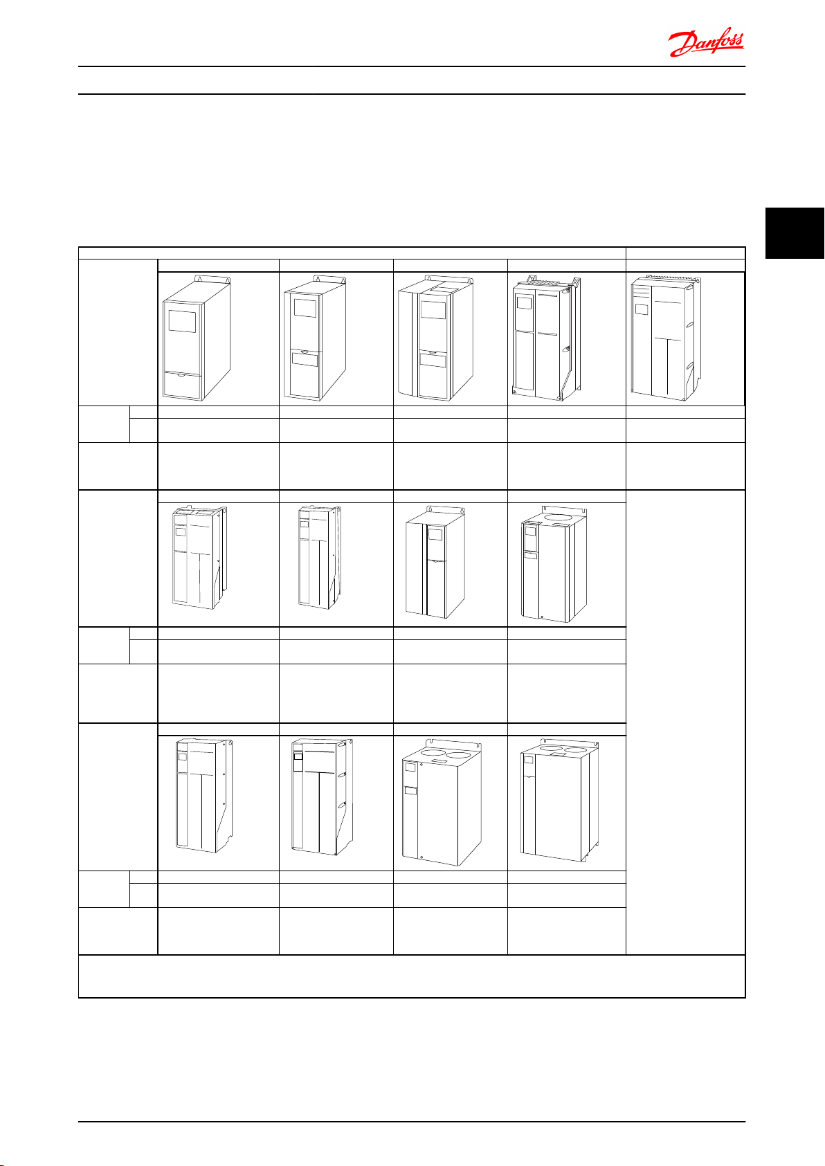
Frame size depends on enclosure type, power range and mains voltage
Frame size A1* A2* A3* A4 A5
Enclosure
protection
High overload
rated power 160% overload
torque
Frame size B1 B2 B3 B4
IP 20/21 20/21 20/21 55/66 55/66
NEM
A
Chassis/Type 1 Chassis/ Type 1 Chassis/ Type 1 Type 12 Type 12
0.25 – 1.5kW (200-240V)
0.37 – 1.5kW (380-480V)
0.25-3kW (200–240V)
0.37-4.0kW (380-480/
500V)
3.7kW (200-240V)
5.5-7.5kW (380-480/500V)
0.75-7.5kW (525-600V )
0.25-3kW (200–240V)
0.37-4.0kW (380-480/500V)
0.25-3.7kW (200-240V)
0.37-7.5kW (380-480/500V)
0.75 -7.5kW (525-600V)
3
3
Enclosure
protection
High overload
rated power 160% overload
torque
Frame size C1 C2 C3 C4
Enclosure
protection
High overload
rated power 160% overload
torque
* A1, A2 and A3 are bookstyle enclosures. All other sizes are compact enclosures.
IP 21/55/66 21/55/66 20 20
NEM
A
IP 21/55/66 21/55/66 20 20
NEM
A
Type 1/Type 12 Type 1/Type 12 Chassis Chassis
5.5-7.5kW (200-240V)
11-15kW (380-480/500V)
11-15kW (525-600V)
Type 1/Type 12 Type 1/Type 12 Chassis Chassis
15-22kW (200-240V)
30-45kW (380-480/500V)
30-45kW (525-600V)
11kW (200-250V)
18.5-22kW
(380-480/500V)
18.5-22kW (525-600V)
11-22kW (525-690V)
30-37kW (200-240V)
55-75kW (380-480/500V)
55-90kW (525-600V)
30-75kW (525-690V)
5.5-7.5kW (200-240V)
11-15kW (380-480/500V)
11-15kW (525-600V)
18.5-22kW (200-240V)
37-45kW (380-480/500V)
37-45kW (525-600V)
11-15kW (200-240V)
18.5-30kW (380-480/500V)
18.5-30kW (525-600V)
30-37kW (200-240V)
55-75kW (380-480/500V)
55-90kW (525-600V)
MG.33.BD.02 - VLT® is a registered Danfoss trademark 15
Page 17
130BA816.10
130BA817.10
130BA819.10
130BA820.10
130BA818.10
130BA821.10
F3
F1
130BA959.10
F4
F3
130BB092.10
F9
F8
130BB690.10
F11
F10
130BB691.10
F13
F12
130BB692.10
3
Introduction to FC 300 FC 300 Design Guide
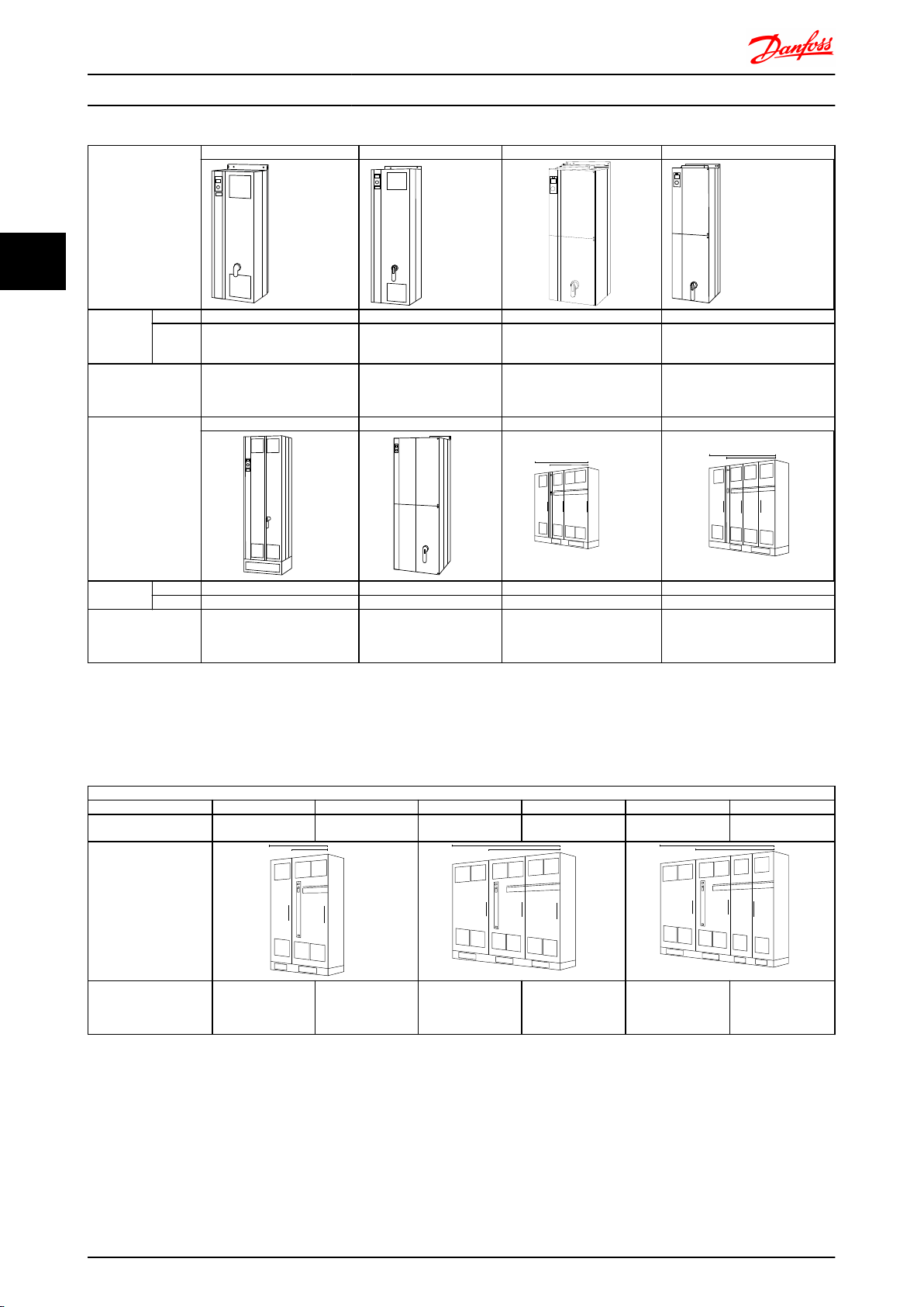
Frame size D1 D2 D3 D4
Enclosure
protection
High overload rated
power - 160%
overload torque
Frame size E1 E2 F1/F3 F2/ F4
Enclosure
protection
High overload rated
power - 160%
overload torque
IP 21/54 21/54 00 00
NEMA Type 1/ Type 12 Type 1/ Type 12 Chassis Chassis
90-110kW at 400V
(380-/ 500V)
37-132kW at 690V
(525-690V)
IP 21/54 00 21/54 21/54
NEMA Type 1/ Type 12 Chassis Type 1/ Type 12 Type 1/ Type 12
250-400kW at 400V
(380-/500V)
355-560kW at 690V
(525-690V)
132-200kW at 400V
(380-/ 500V)
160-315kW at 690V
(525-690V)
250-400kW at 400V
(380-/500V)
355-560kW at 690V
(525-690V)
90-110kW at 400V
(380-/500V)
37-132kW at 690V
(525-690V)
450 - 630kW at 400V
(380 - /500V)
630 - 800kW at 690V
(525-690V)
132-200kW at 400V
(380-/ 500V)
160-315kW at 690V
(525-690V)
710 - 800kW at 400V
(380 - / 500V)
900 - 1000kW at 690V
(525-690V)
NOTE
The F frames are available with or without options cabinet. The F1 and F2 consist of an inverter cabinet on the right and
rectifier cabinet on the left. The F3 and F4 have an additional options cabinet left of the rectifier cabinet. The F3 is an F1
with an additional options cabinet. The F4 is an F2 with an additional options cabinet.
12-Pulse Units
Frame size F8 F9 F10 F11 F12 F13
IP
NEMA
High overload rated
power - 160% overload
torque
21, 54
Type 1/Type 12
250 - 400kW
(380 - 500V)
355 - 560kW
(525-690V)
21, 54
Type 1/Type 12
250 - 400kW
(380 - 500V)
355 - 56kW
(525-690V)
21, 54
Type 1/Type 12
450 - 630kW
(380 - 500V)
630 - 800kW
(525-690V)
21, 54
Type 1/Type 12
450 - 630kW
(380 - 500V)
630 - 800kW
(525-690V)
21, 54
Type 1/Type 12
710 - 800kW
(380 - 500V)
900 - 1200kW
(525-690V)
21, 54
Type 1/Type 12
710 - 800kW
(380 - 500V)
900 - 1200kW
(525-690V)
NOTE
The F frames are available with or without options cabinet. The F8, F10 and F12 consist of an inverter cabinet on the right
and rectifier cabinet on the left. The F9, F11 and F13 have an additional options cabinet left of the rectifier cabinet. The F9
is an F8 with an additional options cabinet. The F11 is an F10 with an additional options cabinet. The F13 is an F12 with an
additional options cabinet.
16 MG.33.BD.02 - VLT® is a registered Danfoss trademark
Page 18

Introduction to FC 300 FC 300 Design Guide
3.2.1 Control Principle
A frequency converter rectifies AC voltage from mains into
DC voltage, after which this DC voltage is converted into a
AC current with a variable amplitude and frequency.
The motor is supplied with variable voltage / current and
frequency, which enables infinitely variable speed control
of three-phased, standard AC motors and permanent
magnet synchronous motors.
3.2.2 FC 300 Controls
The frequency converter is capable of controlling either
the speed or the torque on the motor shaft. Setting
1-00 Configuration Mode determines the type of control.
Speed control:
There are two types of speed control:
Speed open loop control which does not require
•
any feedback from motor (sensorless).
Speed closed loop PID control requires a speed
•
feedback to an input. A properly optimised speed
closed loop control will have higher accuracy
than a speed open loop control.
Selects which input to use as speed PID feedback in
7-00 Speed PID Feedback Source.
Speed / torque reference:
The reference to these controls can either be a single
refrence or be the sum of various references including
relatively scaled references. The handling of references is
explained in detail later in this section.
3
3
Torque control (FC 302 only):
The torque control function is used in applications where
the torque on motor output shaft is controlling the
application as tension control. Torque control can be
selected in par. 1-00, either in VVC+ open loop [4] or Flux
control closed loop with motor speed feedback [2]. Torque
setting is done by setting an analog, digital or bus
controlled reference. The max speed limit factor is set in
par. 4-21. When running torque control it is recommended
to make a full AMA procedure as the correct motor data
are of high importance for optimal performance.
Closed loop in Flux mode with encoder feedback
•
offers superior performance in all four quadrants
and at all motor speeds.
Open loop in VVC+ mode. The function is used in
•
mechanical robust applications, but the accuracy
is limited. Open loop torque function works
basically only in one speed direction. The torque
is calculated on basic of current measurement
internal in the frequency converter. See
Application Example Torque open Loop
MG.33.BD.02 - VLT® is a registered Danfoss trademark 17
Page 19
M
L2 92
L1 91
L3 93
89(+)
88(-)
R+
82
R81
U 96
V 97
W 98
130BA192.12
InrushR inr
Load sharing -
De-saturation protection
Load sharing +
Brake
Resistor
Drive
Control
Board
Inrush
R inr
Load sharing -
Load sharing +
LC Filter (5A)
LC Filter +
(5A)
Brake
Resistor
130BA193.13
M
L2 92
L1 91
L3 93
89(+)
88(-)
R+
82
R81
U 96
V 97
W 98
P 14-50
Introduction to FC 300 FC 300 Design Guide
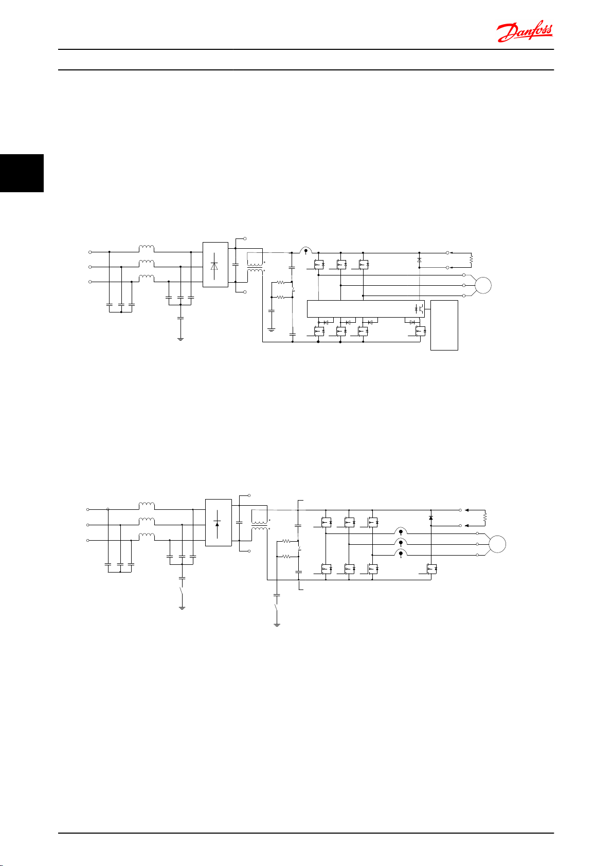
3.2.3 FC 301 vs. FC 302 Control Principle
3
FC 301 is a general purpose frequency converter for variable speed applications. The control principle is based on Voltage
Vector Control (VVC
plus
).
FC 301 can handle asynchronous motors only.
The current sensing principle in FC 301 is based on current measurement in the DC link or motor phase. The ground fault
protection on the motor side is solved by a de-saturation circuit in the IGBTs connected to the control board.
Short circuit behaviour on FC 301 depends on the current transducer in the positive DC link and the desaturation protection
with feedback from the 3 lower IGBT's and the brake.
Illustration 3.1 FC 301
FC 302 is a high performance frequency converter for demanding applications. The frequency converter can handle various
kinds of motor control principles such as U/f special motor mode, VVC
plus
or Flux Vector motor control.
FC 302 is able to handle Permanent Magnet Synchronous Motors (Brushless servo motors) as well as normal squirrel cage
asynchronous motors.
Short circuit behaviour on FC 302 depends on the 3 current transducers in the motor phases and the desaturation
protection with feedback from the brake.
Illustration 3.2 FC 302
18 MG.33.BD.02 - VLT® is a registered Danfoss trademark
Page 20
+
_
+
_
Cong. mode
Ref.
Process
P 1-00
High
+f max.
Low
-f max.
P 4-11
Motor speed
low limit (RPM)
P 4-12
Motor speed
low limit (Hz)
P 4-13
Motor speed
high limit (RPM)
P 4-14
Motor speed
high limit (Hz)
Motor
controller
Ramp
Speed
PID
P 7-20 Process feedback
1 source
P 7-22 Process feedback
2 source
P 7-00 Speed PID
feedback source
P 1-00
Cong. mode
P 4-19
Max. output freq.
-f max.
Motor
controller
P 4-19
Max. output freq.
+f max.
P 3-**
P 7-0*
130BA055.10
Introduction to FC 300 FC 300 Design Guide
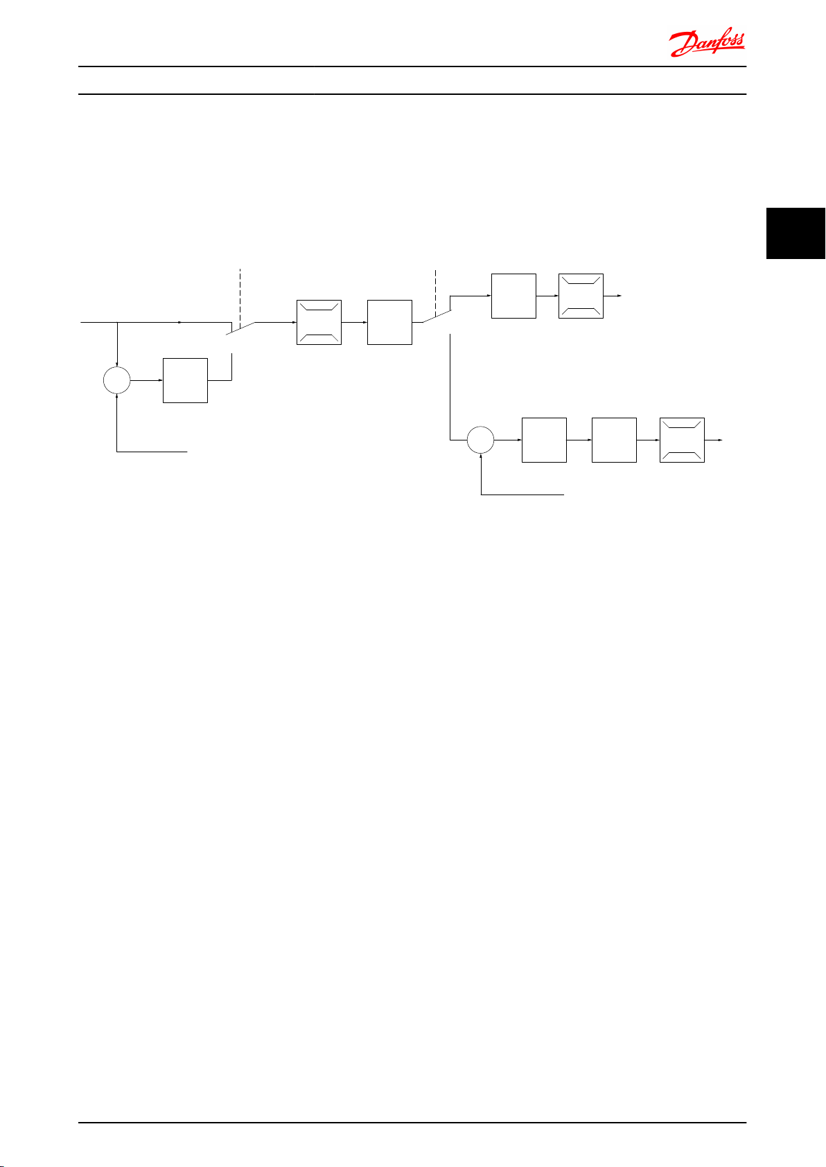
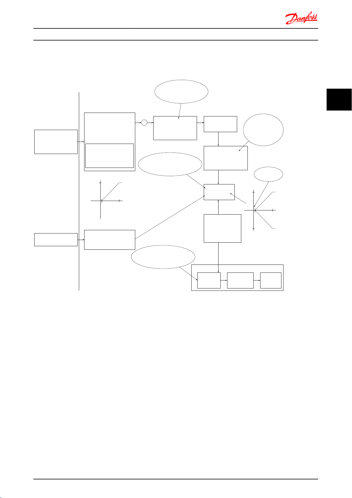
3.2.4
Control Structure in VVC
Control structure in VVC
plus
Advanced Vector Control
plus
open loop and closed loop configurations:
3
3
In the configuration shown in Illustration 3.3, 1-01 Motor Control Principle is set to “VVC
plus
[1]” and 1-00 Configuration Mode is
set to “Speed open loop [0]”. The resulting reference from the reference handling system is received and fed through the
ramp limitation and speed limitation before being sent to the motor control. The output of the motor control is then
limited by the maximum frequency limit.
If 1-00 Configuration Mode is set to “Speed closed loop [1]” the resulting reference will be passed from the ramp limitation
and speed limitation into a speed PID control. The Speed PID control parameters are located in the parameter group 7-0*.
The resulting reference from the Speed PID control is sent to the motor control limited by the frequency limit.
Select “Process [3]” in 1-00 Configuration Mode to use the process PID control for closed loop control of e.g. speed or
pressure in the controlled application. The Process PID parameters are located in parameter group 7-2* and 7-3*.
MG.33.BD.02 - VLT® is a registered Danfoss trademark 19
Page 21
+
_
+
_
130BA053.11
Ref.
Cong. mode
P 1-00
P 7-20 Process feedback
1 source
P 7-22 Process feedback
2 source
Process
PID
P 4-11 Motor speed
low limit [RPM]
P 4-12 Motor speed
low limit [Hz]
P 4-14 Motor speed
high limit [Hz]
P 4-13 Motor speed
high limit [RPM]
Low
High
Ramp
P 3-**
+f max.
P 4-19
Max. output
freq.
Motor
controller
-f max.
Speed
PID
P 7-0*
3
Introduction to FC 300 FC 300 Design Guide
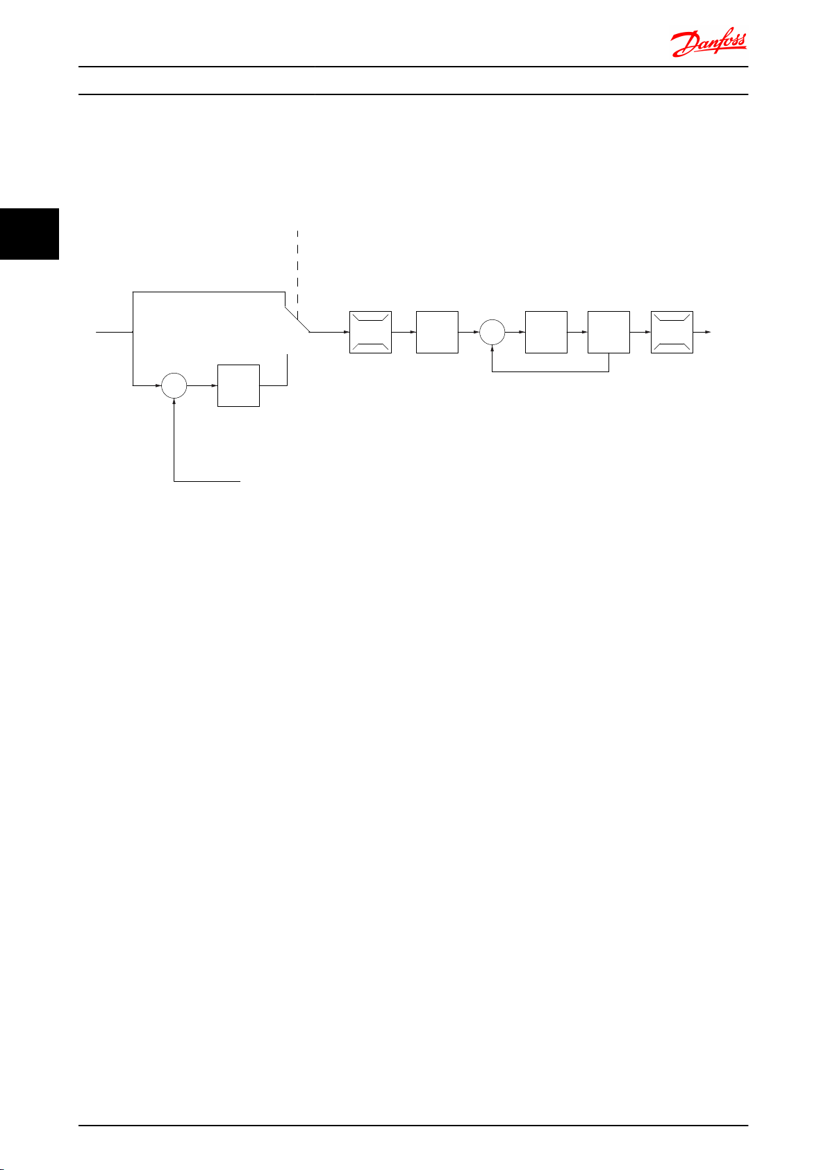
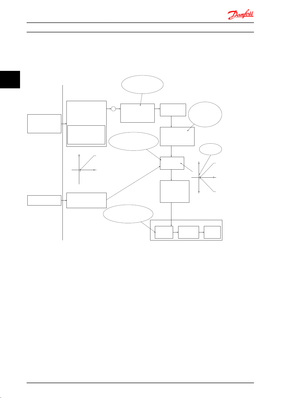
3.2.5 Control Structure in Flux Sensorless (FC 302 only)
Control structure in Flux sensorless open loop and closed loop configurations.
In the shown configuration,
1-01 Motor Control Principle is set to “Flux sensorless [2]” and 1-00 Configuration Mode is set to
“Speed open loop [0]”. The resulting reference from the reference handling system is fed through the ramp and speed
limitations as determined by the parameter settings indicated.
An estimated speed feedback is generated to the Speed PID to control the output frequency.
The Speed PID must be set with its P,I, and D parameters (parameter group 7-0*).
Select “Process [3]” in 1-00 Configuration Mode to use the process PID control for closed loop control of i.e. speed or
pressure in the controlled application. The Process PID parameters are found in parameter group 7-2* and 7-3*.
20 MG.33.BD.02 - VLT® is a registered Danfoss trademark
Page 22
130BA054.11
P 3-** P 7-0*P 7-2*
+
_
+
_
P 7-20 Process feedback
1 source
P 7-22 Process feedback
2 source
P 4-11 Motor speed
low limit (RPM)
P 4-12 Motor speed
low limit (Hz)
P 4-13 Motor speed
high limit (RPM)
P 4-14 Motor speed
high limit (Hz)
High
Low
Ref.
Process
PID
Speed
PID
Ramp
P 7-00
PID source
Motor
controller
-f max.
+f max.
P 4-19
Max. output
freq.
P 1-00
Cong. mode
P 1-00
Cong. mode
Torque
Introduction to FC 300 FC 300 Design Guide
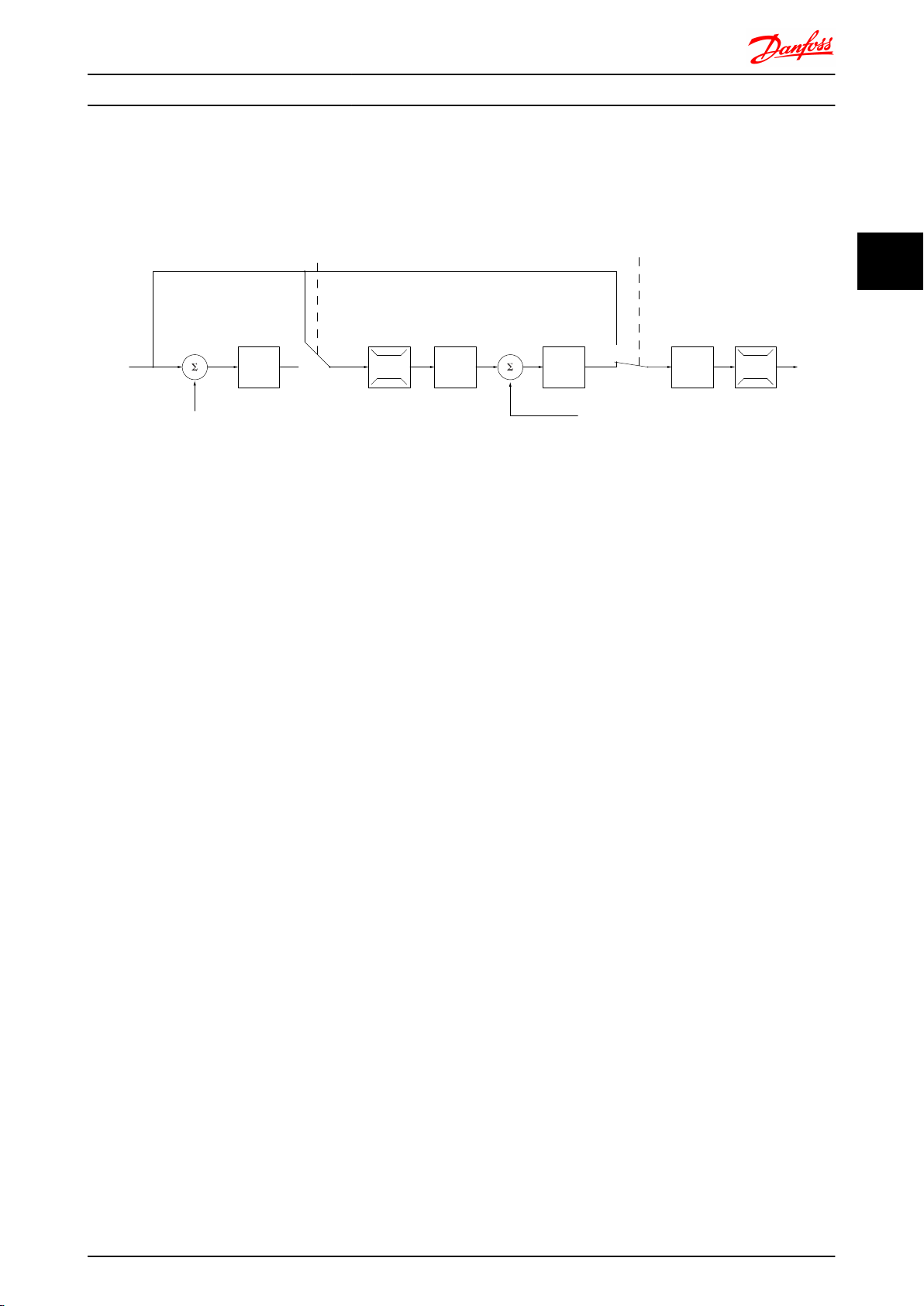
3.2.6 Control Structure in Flux with Motor Feedback
Control structure in Flux with motor feedback configuration (only available in FC 302):
In the shown configuration, 1-01 Motor Control Principle is set to “Flux w motor feedb [3]” and 1-00 Configuration Mode is set
to “Speed closed loop [1]”.
3
3
The motor control in this configuration relies on a feedback signal from an encoder mounted directly on the motor (set in
1-02 Flux Motor Feedback Source).
Select “Speed closed loop [1]” in 1-00 Configuration Mode to use the resulting reference as an input for the Speed PID
control. The Speed PID control parameters are located in parameter group 7-0*.
Select “Torque [2]” in 1-00 Configuration Mode to use the resulting reference directly as a torque reference. Torque control
can only be selected in the Flux with motor feedback (1-01 Motor Control Principle) configuration. When this mode has been
selected, the reference will use the Nm unit. It requires no torque feedback, since the actual torque is calculated on the
basis of the current measurement of the frequency converter.
Select “Process [3]” in 1-00 Configuration Mode to use the process PID control for closed loop control of e.g. speed or a
process variable in the controlled application.
MG.33.BD.02 - VLT® is a registered Danfoss trademark 21
Page 23
130BP046.10
Hand
on
O
Auto
on
Reset
Remote
reference
Local
reference
Auto mode
Hand mode
Linked to hand/auto
Local
Remote
Reference
130BA245.11
LCP Hand on,
o and auto
on keys
P 3-13
Reference site
Torque
Speed open/
closed loop
Scale to
RPM or
Hz
Scale to
Nm
Scale to
process
unit
Process
closed loop
Local
ref.
Local
reference
Conguration
mode
Local
conguration
mode
130BA246.10
P 1-00
P 1-05
Introduction to FC 300 FC 300 Design Guide
3
3.2.7
Internal Current Control in VVC
plus
Mode
The frequency converter features an integral current limit
control which is activated when the motor current, and
thus the torque, is higher than the torque limits set in
4-16 Torque Limit Motor Mode, 4-17 Torque Limit Generator
Mode and 4-18 Current Limit.
When the frequency converter is at the current limit during
motor operation or regenerative operation, the frequency
converter will try to get below the preset torque limits as
quickly as possible without losing control of the motor.
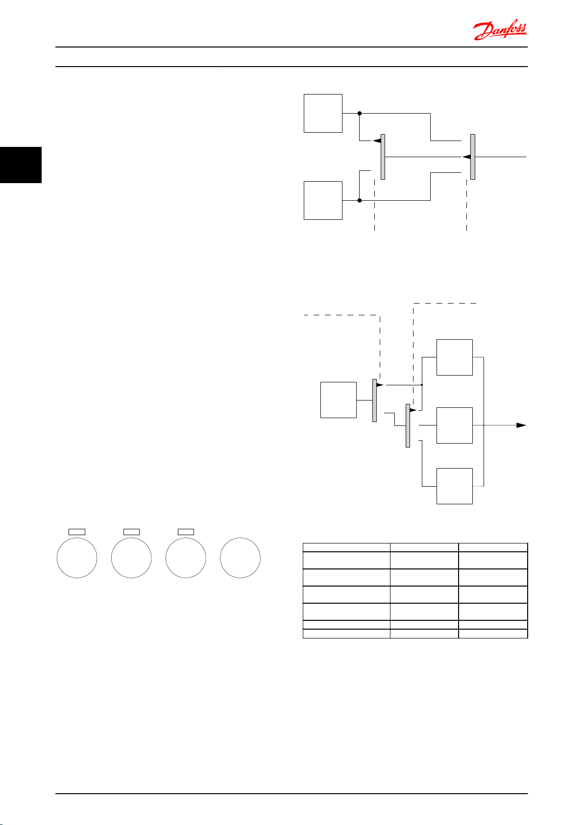
Local (Hand On) and Remote (Auto
3.2.8
On) Control
The frequency converter can be operated manually via the
local control panel (LCP) or remotely via analog and digital
inputs and serial bus. If allowed in 0-40 [Hand on] Key on
LCP, 0-41 [Off] Key on LCP, 0-42 [Auto on] Key on LCP, and
0-43 [Reset] Key on LCP, it is possible to start and stop the
frequency converter via the LCP using the [Hand ON] and
[Off] keys. Alarms can be reset via the [RESET] key. After
pressing the [Hand ON] key, the frequency converter goes
into Hand mode and follows (as default) the Local
reference that can be set using arrow key on the LCP.
After pressing the [Auto On] key, the frequency converter
goes into Auto mode and follows (as default) the Remote
reference. In this mode, it is possible to control the
frequency converter via the digital inputs and various serial
interfaces (RS-485, USB, or an optional fieldbus). See more
about starting, stopping, changing ramps and parameter
set-ups etc. in parameter group 5-1* (digital inputs) or
parameter group 8-5* (serial communication).
Hand OnAutoLCP Keys
Hand Linked to Hand /
Active Reference and Configuration Mode
The active reference can be either the local reference or
the remote reference.
In 3-13 Reference Site the local reference can be
permanently selected by selecting Local [2].
To permanently select the remote reference select Remote
[1]. By selecting Linked to Hand/Auto [0] (default) the
reference site will depend on which mode is active. (Hand
Mode or Auto Mode).
Hand -> Off Linked to Hand /
Auto Linked to Hand /
Auto -> Off Linked to Hand /
All keys Local Local
All keys Remote Remote
Table 3.1 Conditions for Local/Remote Reference Activation.
1-00 Configuration Mode determines what kind of
application control principle (i.e. Speed, Torque or Process
Control) is used when the remote reference is active.
1-05 Local Mode Configuration determines the kind of
application control principle that is used when the local
reference is active. One of them is always active, but both
can not be active at the same time.
22 MG.33.BD.02 - VLT® is a registered Danfoss trademark
3-13 Reference Site
Auto
Auto
Auto
Auto
Active Reference
Local
Local
Remote
Remote
Page 24
No function
Analog ref.
Pulse ref.
Local bus ref.
Preset relative ref.
Preset ref.
Local bus ref.
No function
Analog ref.
Pulse ref.
Analog ref.
Pulse ref.
Local bus ref.
No function
Local bus ref.
Pulse ref.
No function
Analog ref.
Input command:
Catch up/ slow down
Catchup Slowdown
value
Freeze ref./Freeze output
Speed up/ speed down
ref.
Remote
Ref. in %
-max ref./
+max ref.
Scale to
RPM or
Hz
Scale to
Nm
Scale to
process
unit
Relative
X+X*Y
/100
DigiPot
DigiPot
DigiPot
max ref.
min ref.
DigiPot
D1
P 5-1x(15)
Preset '1'
External '0'
Process
Torque
Speed
open/closed loop
(1)
(2)
(3)
(4)
(5)
(6)
(7)
(0)
(0)
(1)
Relative scaling ref.
P 3-18
Ref.resource 1
P 3-15
Ref. resource 2
P 3-16
Ref. resource 3
P 3-17
200%
-200%
Y
X
-100%
100%
%
%
Ref./feedback range
P 3-00
Conguration mode
P 1-00
P 3-14
±100%
130BA244.11
P 16-01
P 16-02
P 3-12
P 5-1x(21)/P 5-1x(22)
P 5-1x(28)/P 5-1x(29)
P 5-1x(19)/P 5-1x(20)
P 3-04
Freeze ref.
&
increase/
decrease
ref.
Catch up/
slow
down
P 3-10
Introduction to FC 300 FC 300 Design Guide
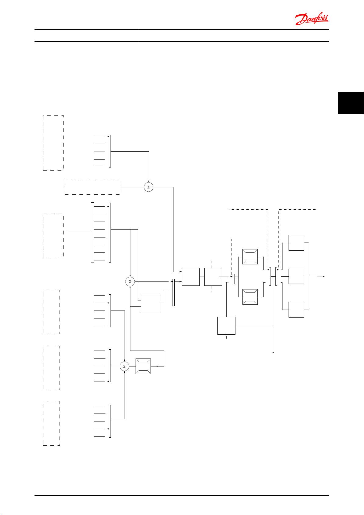
3.3 Reference Handling
Local Reference
The local reference is active when the frequency converter is operated with ‘Hand On’ button active. Adjust the reference by
up/down and left/right arrows respectively.
Remote Reference
The reference handling system for calculating the Remote reference is shown in Illustration 3.3.
3
3
Illustration 3.3 Remote reference
MG.33.BD.02 - VLT® is a registered Danfoss trademark 23
Page 25
Resulting reference
Sum of all
references
Forward
Reverse
P 3-00 Reference Range= [0] Min-Max
130BA184.10
-P 3-03
P 3-03
P 3-02
-P 3-02
P 3-00 Reference Range =[1]-Max-Max
Resulting reference
Sum of all
references
-P 3-03
P 3-03
130BA185.10
130BA186.11
P 3-03
P 3-02
Sum of all
references
P 3-00 Reference Range= [0] Min to Max
Resulting reference
3
Introduction to FC 300 FC 300 Design Guide
The Remote Reference is calculated once every scan
interval and initially consists of two types of reference
inputs:
1. X (the external reference): A sum (see
3-04 Reference Function) of up to four externally
selected references, comprising any combination
(determined by the setting of 3-15 Reference
Resource 1, 3-16 Reference Resource 2 and
3-17 Reference Resource 3) of a fixed preset
reference (3-10 Preset Reference), variable analog
references, variable digital pulse references, and
various serial bus references in whatever unit the
frequency converter is controlled ([Hz], [RPM],
[Nm] etc.).
2. Y- (the relative reference): A sum of one fixed
preset reference (3-14 Preset Relative Reference)
and one variable analog reference (3-18 Relative
Scaling Reference Resource) in [%].
The two types of reference inputs are combined in the
following formula: Remote reference = X + X * Y / 100%. If
relative reference is not used par. 3-18 must be set to No
function and par. 3-14 to 0%. The catch up / slow down
function and the freeze reference function can both be
activated by digital inputs on the frequency converter. The
functions and parameters are described in the
Programming Guide, MG33MXYY.
The scaling of analog references are described in
parameter groups 6-1* and 6-2*, and the scaling of digital
pulse references are described in parameter group 5-5*.
Reference limits and ranges are set in parameter group
3-0*.
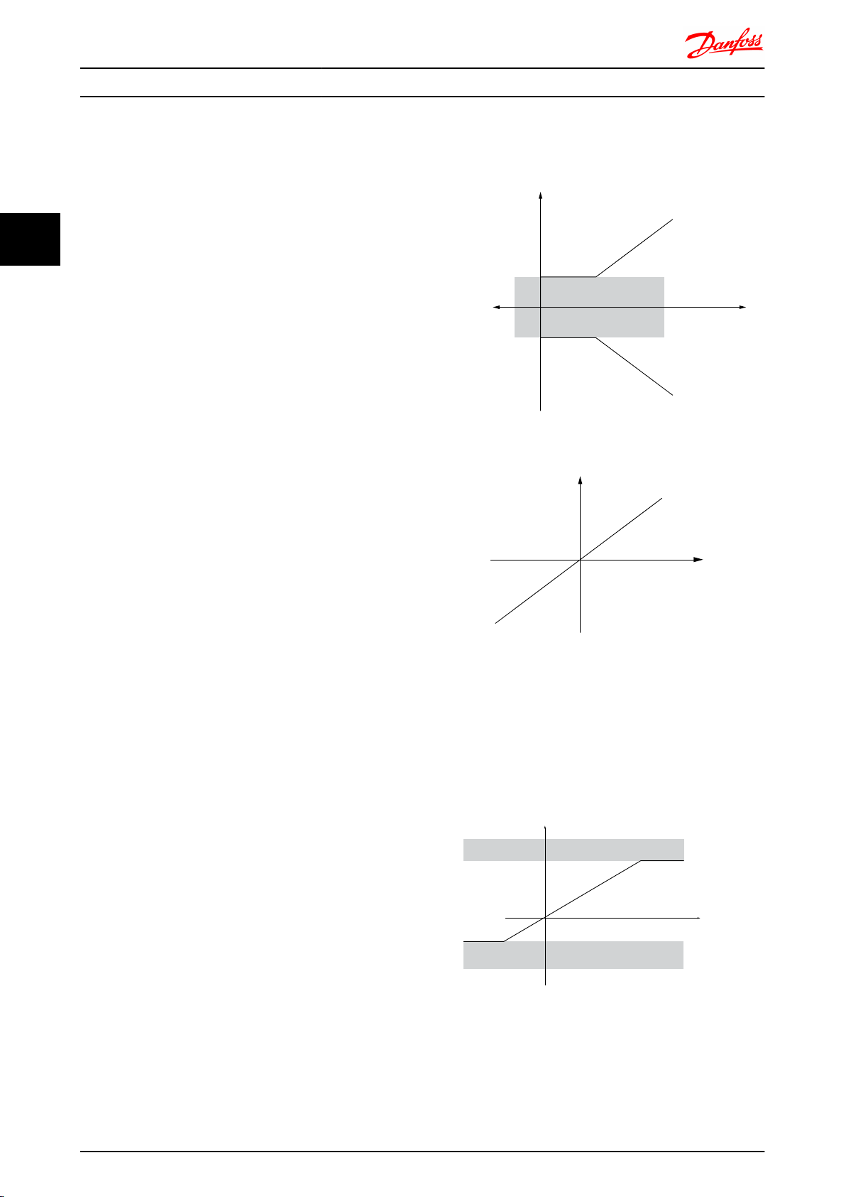
Reference Limits
3.3.1
3-00 Reference Range , 3-02 Minimum Reference and
3-03 Maximum Reference together define the allowed range
of the sum of all references. The sum of all references are
clamped when necessary. The relation between the
resulting reference (after clamping) and the sum of all
references is shown below.
The value of 3-02 Minimum Reference can not be set to less
than 0, unless1-00 Configuration Mode is set to [3] Process.
In that case the following relations between the resulting
reference (after clamping) and the sum of all references is
as shown in Illustration 3.4.
24 MG.33.BD.02 - VLT® is a registered Danfoss trademark
Illustration 3.4 Sum of all References
Page 26
(RPM)
Resource output
Resource
input
Terminal X low
Terminal X
high
Low reference/feedback value
High reference/feedback
value
130BA181.10
-1500
-6 8 (V)
1500
-10 10
P1
P2
0
-600
(RPM)
Resource output
Resource
input
Terminal X low
Terminal X
high
Low reference/feedback value
High reference/feedback
value
130BA182.10
-1500
-6 8 (V)
1500
-10 10
P1
P2
0
-600
Introduction to FC 300 FC 300 Design Guide
3.3.2 Scaling of Preset References and Bus
References
Preset references are scaled according to the following
rules:
When 3-00 Reference Range : [0] Min - Max 0%
•
reference equals 0 [unit] where unit can be any
unit e.g. rpm, m/s, bar etc. 100% reference equals
the Max (abs (3-03 Maximum Reference ), abs
(3-02 Minimum Reference)).
When 3-00 Reference Range : [1] -Max - +Max 0%
•
reference equals 0 [unit] -100% reference equals Max Reference 100% reference equals Max
Reference.
Bus references are scaled according to the following rules:
When 3-00 Reference Range: [0] Min - Max. To
•
obtain max resolution on the bus reference the
scaling on the bus is: 0% reference equals Min
Reference and 100% reference equals Max
reference.
When 3-00 Reference Range: [1] -Max - +Max
•
-100% reference equals -Max Reference 100%
reference equals Max Reference.
3
3
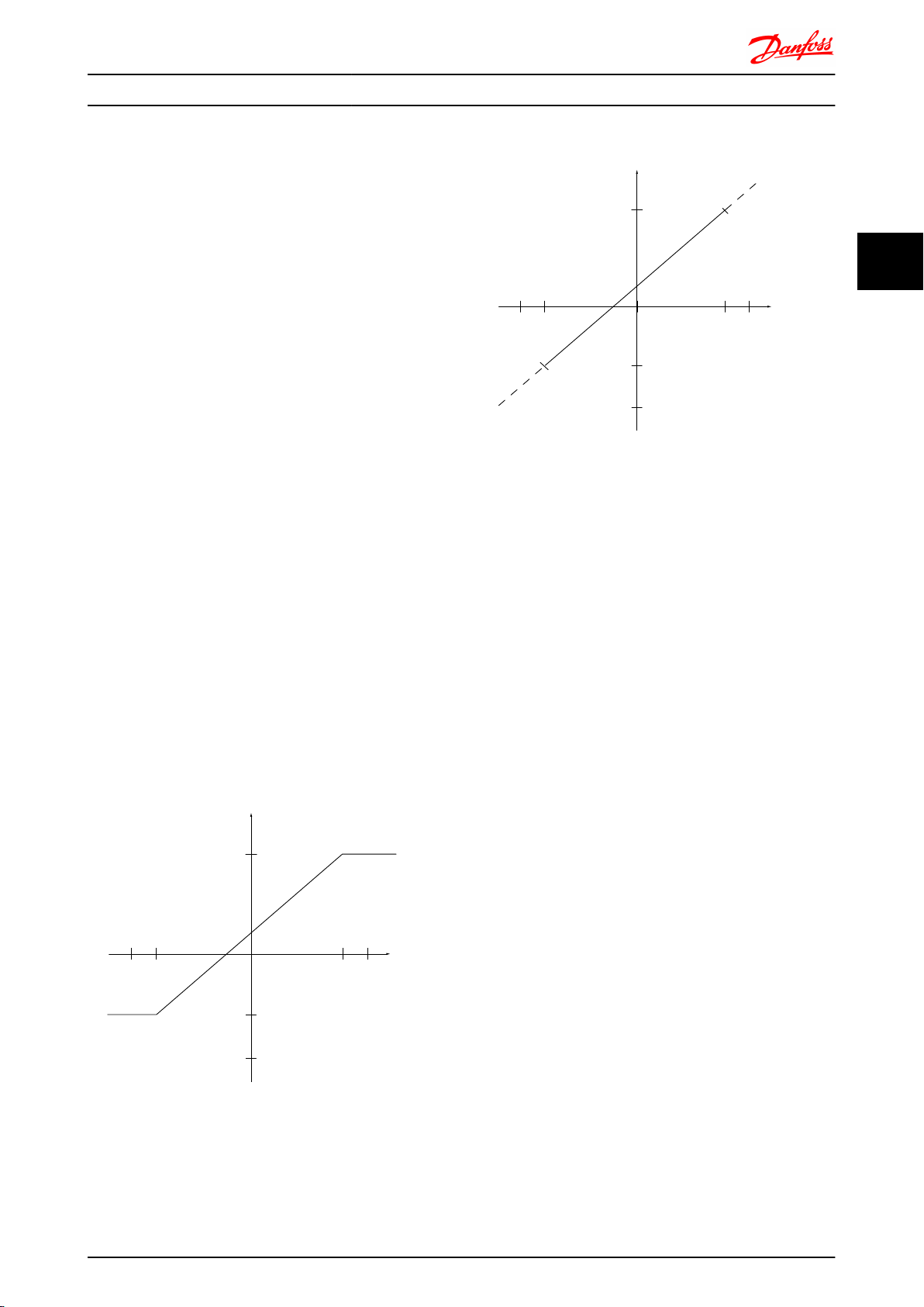
3.3.3
References and feedback are scaled from analog and pulse
inputs in the same way. The only difference is that a
reference above or below the specified minimum and
maximum “endpoints” (P1 and P2 in Illustration 3.5) are
clamped whereas a feedback above or below is not.
Scaling of Analog and Pulse
References and Feedback
Illustration 3.5 Scaling of Analog and Pulse References and
Feedback
MG.33.BD.02 - VLT® is a registered Danfoss trademark 25
Page 27
(RPM)
Resource output
Resource
input
Quadrant 2
Quadrant 3
Quadrant 1
Quadrant 4
Terminal X
low
Terminal X
high
Low reference/feedback
value
High reference/feedback
value
-1 1
130BA179.10
-1500
-6 6
(V)
1500
-10 10
P1P20
(RPM)
Resource output
Resource
input
Quadrant 2
Quadrant 3
Quadrant 1
Quadrant 4
Terminal X
low
Terminal X
high
Low reference/feedback
value
High reference/feedback
value
-1 1
130BA180.10
-1500
-6 6
(V)
1500
-10 10
P1
P2
0
Introduction to FC 300 FC 300 Design Guide
The endpoints P1 and P2 are defined by the following parameters depending on which analog or pulse input is used
3
Analog 53
S201=OFF
P1 = (Minimum input value, Minimum reference value)
Minimum reference value
Minimum input value
P2 = (Maximum input value, Maximum reference value)
Maximum reference value
Maximum input value
6-14 Terminal 53
Low Ref./Feedb.
Value
6-10 Terminal 53
Low Voltage [V]
6-15 Terminal 53
High Ref./Feedb.
Value
6-11 Terminal 53
High Voltage [V]
Analog 53
S201=ON
6-14 Terminal 53
Low Ref./Feedb.
Value
6-12 Terminal 53
Low Current [mA]
6-15 Terminal 53
High Ref./Feedb.
Value
6-13 Terminal 53
High Current [mA]
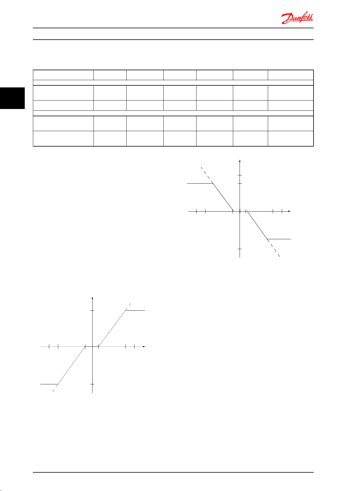
3.3.4 Dead Band Around Zero
In some cases the reference (in rare cases also the
feedback) should have a Dead Band around zero (i.e. to
make sure the machine is stopped when the reference is
“near zero”).
To make the dead band active and to set the amount of
dead band, the following settings must be done:
Either Minimum Reference Value (see table above
•
for relevant parameter) or Maximum Reference
Value must be zero. In other words; Either P1 or
P2 must be on the X-axis in the graph below.
And both points defining the scaling graph are in
•
the same quadrant.
The size of the Dead Band is defined by either P1 or P2 as
shown inIllustration 3.6.
Analog 54
S202=OFF
6-24 Terminal 54
Low Ref./Feedb.
Value
6-20 Terminal 54
Low Voltage [V]
6-25 Terminal 54
High Ref./Feedb.
Value
6-21 Terminal 54
High Voltage[V]
Analog 54
S202=ON
6-24 Terminal 54
Low Ref./Feedb.
Value
6-22 Terminal 54
Low Current [mA]
6-25 Terminal 54
High Ref./Feedb.
Value
6-23 Terminal 54
High Current[mA]
Pulse Input 29 Pulse Input 33
5-52 Term. 29 Low
Ref./Feedb. Value
5-50 Term. 29 Low
Frequency [Hz]
5-53 Term. 29
High Ref./Feedb.
Value
5-51 Term. 29
High Frequency
[Hz]
5-57 Term. 33 Low Ref./
Feedb. Value
5-55 Term. 33 Low
Frequency [Hz]
5-58 Term. 33 High Ref./
Feedb. Value
5-56 Term. 33 High
Frequency [Hz]
Thus a reference endpoint of P1 = (0 V, 0 RPM) will not
result in any dead band, but a reference endpoint of e.g.
P1 = (1V, 0 RPM) will result in a -1V to +1V dead band in
this case provided that the end point P2 is placed in either
Quadrant 1 or Quadrant 4.
26 MG.33.BD.02 - VLT® is a registered Danfoss trademark
Page 28
500
1
10
V
V
500
1
10
-500
130BA187.11
+
Analog input 53
Low reference 0 RPM
High reference 500 RPM
Low voltage 1V
High voltage 10V
Ext. source 1
Range:
0,0% (0 RPM)
100,0% (500 RPM)
100,0% (500 RPM)
Ext. reference
Range:
0,0% (0 RPM)
500 RPM 10V
Ext. Reference
Absolute
0 RPM 1V
Reference
algorithm
Reference
100,0% (500 RPM)
0,0% (0 RPM)
Range:
Limited to:
0%- +100%
(0 RPM- +500 RPM)
Limited to: -200%- +200%
(-1000 RPM- +1000 RPM)
Reference is scaled
according to min
max reference giving a
speed.!!!
Scale to
speed
+500 RPM
-500 RPM
Range:
Speed
setpoint
Motor
control
Range:
-200 RPM
+200 RPM
Motor
Digital input 19
Low No reversing
High Reversing
Limits Speed Setpoint
according to min max speed.!!!
Motor PID
RPM
RPM
Dead band
Digital input
General Reference
parameters:
Reference Range: Min - Max
Minimum Reference: 0 RPM (0,0%)
Maximum Reference: 500 RPM (100,0%)
General Motor
parameters:
Motor speed direction:Both directions
Motor speed Low limit: 0 RPM
Motor speed high limit: 200 RPM
Introduction to FC 300 FC 300 Design Guide
Case 1: Positive Reference with Dead band, Digital input to trigger reverse
This Case shows how Reference input with limits inside Min – Max limits clamps.
3
3
MG.33.BD.02 - VLT® is a registered Danfoss trademark 27
Page 29
+
750
1
10
500
1
10
130BA188.13
-500
V
V
Analog input 53
Low reference 0 RPM
High reference 500 RPM
Low voltage 1V
High voltage 10V
Ext. source 1
Range:
0,0% (0 RPM)
150,0% (750 RPM)
150,0% (750 RPM)
Ext. reference
Range:
0,0% (0 RPM)
750 RPM 10V
Ext. Reference
Absolute
0 RPM 1V
Reference
algorithm
Reference
100,0% (500 RPM)
0,0% (0 RPM)
Range:
Limited to:
-100%- +100%
(-500 RPM- +500 RPM)
Limited to: -200%- +200%
(-1000 RPM- +1000 RPM)
Reference is scaled
according to
max reference giving a
speed.!!!
Scale to
speed
+500 RPM
-500 RPM
Range:
Speed
setpoint
Motor
control
Range:
-200 RPM
+200 RPM
Motor
Digital input 19
Low No reversing
High Reversing
Limits Speed Setpoint
according to min max speed.!!!
Motor PID
Dead band
Digital input
General Reference
parameters:
Reference Range: -Max - Max
Minimum Reference: Don't care
Maximum Reference: 500 RPM (100,0%)
General Motor
parameters:
Motor speed direction:Both directions
Motor speed Low limit: 0 RPM
Motor speed high limit: 200 RPM
3
Introduction to FC 300 FC 300 Design Guide
Case 2: Positive Reference with Dead band, Digital input to trigger reverse. Clamping rules.
This Case shows how Reference input with limits outside -Max – +Max limits clamps to the inputs low and high limits
before addition to External reference. And how the External reference is clamped to -Max – +Max by the Reference
algorithm.
28 MG.33.BD.02 - VLT® is a registered Danfoss trademark
Page 30
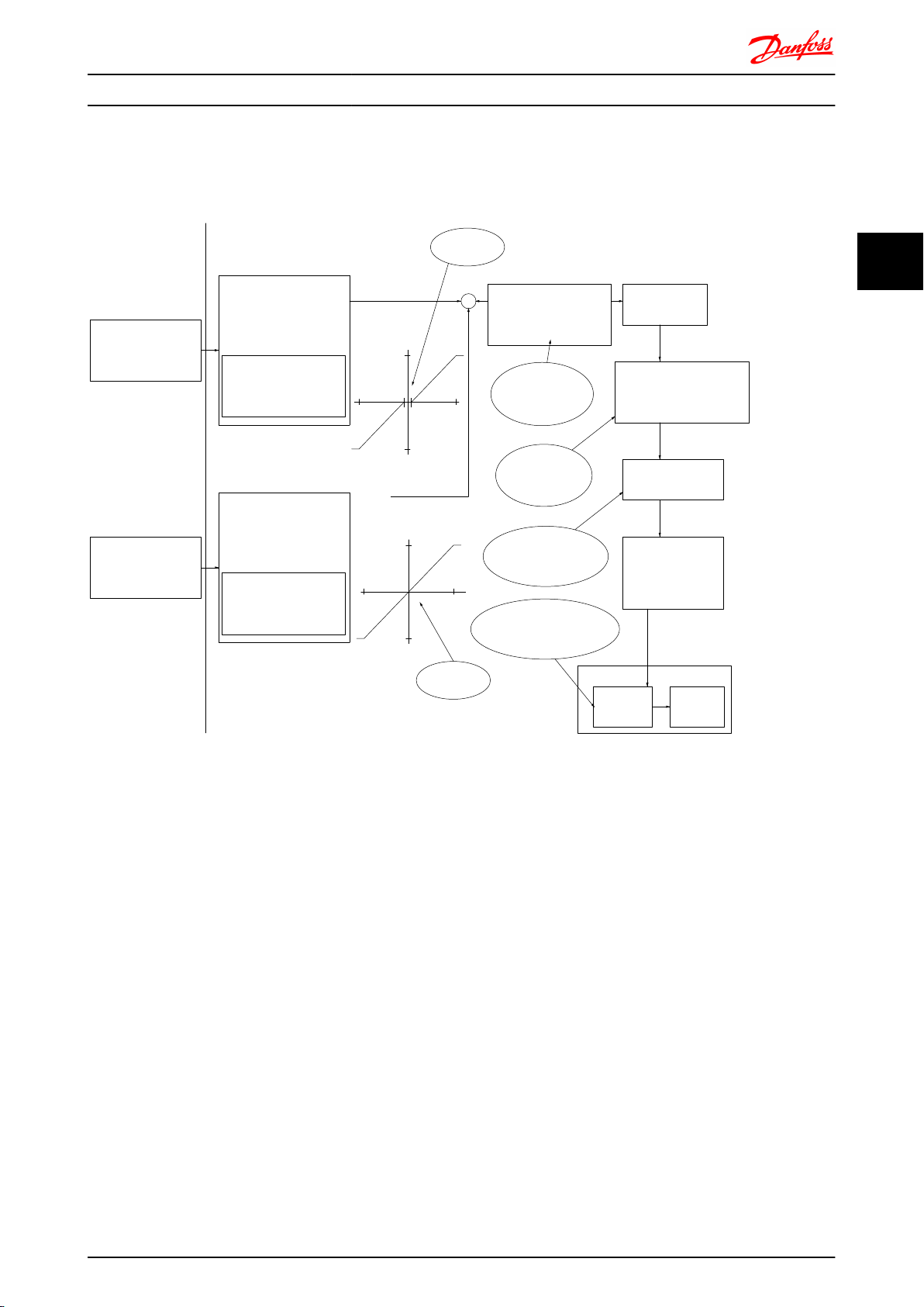
+
500
10
V
130BA189.12
-10
-500
-1
500
-500
-10
1
10
V
Analog input 53
Low reference 0 RPM
High reference +500 RPM
Low voltage 1V
High voltage 10V
Ext. source 1
Range:
-50,0% (-500 RPM)
+50,0% (+500 RPM)
+100,0% (+1000 RPM)
Ext. reference
Range:
-100,0% (-1000 RPM)
+500 RPM 10V
Ext. Reference
Absolute
-500 RPM -10V
Reference
algorithm
Reference
+100,0% (+1000 RPM)
-100,0% (-1000 RPM)
Range:
Limited to:
-100%- +100%
(-1000 RPM-
+1000 RPM)
Limited to:
-200%- +200%
(-2000 RPM-
+2000 RPM)
Reference is scaled
according to max
reference.!!!
Scale to
RPM
+1000 RPM
-1000 RPM
Range:
Speed
setpoint
Motor
control
Motor
Limits Speed to min max
motor speed.!!!
Motor PID
RPM
Dead band
General Reference
parameters:
Reference Range: -Max - +Max
Minimum Reference: Don't care
Maximum Reference: 1000 RPM (100,0%)
General Motor
parameters:
Motor speed direction:Both directions
Motor speed Low limit: 0 RPM
Motor speed high limit: 1500 RPM
-1V to 1V
RPM
-500 RPM -10V
Ext. Reference
+500 RPM 10V
Absolute
+50,0% (+500 RPM)
-50,0% (-500 RPM)
High reference +500 RPM
Ext. source 2
Low reference -500 RPM
Analog input 54
Range:
High voltage +10V
Low voltage -10V
No Dead
band
Introduction to FC 300 FC 300 Design Guide
Case 3: Negative to positive reference with dead band, Sign determines the direction, -Max – +Max
3
3
MG.33.BD.02 - VLT® is a registered Danfoss trademark 29
Page 31

M
3
96 97 9998
91 92 93 95
50
12
L1 L2L1PEL3
W PEVU
F1
L2
L3
N
PE
18
53
37
55
20
32
33
39
24 Vdc
130BA174.10
Introduction to FC 300 FC 300 Design Guide
3.4 PID Control
3.4.1 Speed PID Control
3
1-00 Configuration Mode 1-01 Motor Control Principle
U/f
[0] Speed open loop Not Active Not Active ACTIVE N.A.
[1] Speed closed loop N.A. ACTIVE N.A. ACTIVE
[2] Torque N.A. N.A. N.A. Not Active
[3] Process Not Active ACTIVE ACTIVE
VVC
plus
Flux Sensorless Flux w/ enc. feedb
Table 3.2 Control configurations where the Speed Control is active
“N.A.” means that the specific mode is not available at all. “Not Active” means that the specific mode is available but the Speed Control is not
active in that mode.
NOTE
The Speed Control PID will work under the default parameter setting, but tuning the parameters is highly recommended to
optimize the motor control performance. The two Flux motor control principles are particularly dependant on proper tuning
to yield their full potential.
The following parameters are relevant for the Speed Control:
Parameter Description of function
7-00 Speed PID Feedback Source
30-83 Speed PID Proportional Gain
7-03 Speed PID Integral Time
7-04 Speed PID Differentiation Time
7-05 Speed PID Diff. Gain Limit
7-06 Speed PID Lowpass Filter Time
Select from which input the Speed PID should get its feedback.
The higher the value - the quicker the control. However, too high value may lead to oscillations.
Eliminates steady state speed error. Lower value means quick reaction. However, too low value may lead to
oscillations.
Provides a gain proportional to the rate of change of the feedback. A setting of zero disables the differentiator.
If there are quick changes in reference or feedback in a given application - which means that the error changes
swiftly - the differentiator may soon become too dominant. This is because it reacts to changes in the error. The
quicker the error changes, the stronger the differentiator gain is. The differentiator gain can thus be limited to allow
setting of the reasonable differentiation time for slow changes and a suitably quick gain for quick changes.
A low-pass filter that dampens oscillations on the feedback signal and improves steady state performance. However,
too large filter time will deteriorate the dynamic performance of the Speed PID control.
Practical settings of parameter 7-06 taken from the number of pulses per revolution on from encoder (PPR):
Encoder PPR
512 10 ms
1024 5 ms
2048 2 ms
4096 1 ms
7-06 Speed PID Lowpass Filter Time
Example of how to Programme the Speed Control
In this case the Speed PID Control is used to maintain a
constant motor speed regardless of the changing load on
the motor. The required motor speed is set via a potentiometer connected to terminal 53. The speed range is 0 1500 RPM corresponding to 0 - 10V over the
potentiometer. Starting and stopping is controlled by a
switch connected to terminal 18. The Speed PID monitors
the actual RPM of the motor by using a 24V (HTL)
incremental encoder as feedback. The feedback sensor is
an encoder (1024 pulses per revolution) connected to
terminals 32 and 33.
30 MG.33.BD.02 - VLT® is a registered Danfoss trademark
Page 32

Introduction to FC 300 FC 300 Design Guide
The following must be programmed in order shown (see explanation of settings in the Programming Guide)
In the list it is assumed that all other parameters and switches remain at their default setting.
Function parameter no. Setting
1) Make sure the motor runs properly. Do the following:
Set the motor parameters using name plate data 1-2* As specified by motor name plate
Have the frequency converter makes an Automatic Motor
Adaptation
2) Check the motor is running and the encoder is attached properly. Do the following:
Press the “Hand On” LCP key. Check that the motor is running
and note in which direction it is turning (henceforth referred to
as the “positive direction”).
Go to 16-20 Motor Angle. Turn the motor slowly in the positive
direction. It must be turned so slowly (only a few RPM) that it
can be determined if the value in 16-20 Motor Angle is increasing
or decreasing.
If 16-20 Motor Angle is decreasing then change the encoder
direction in 5-71 Term 32/33 Encoder Direction.
3) Make sure the drive limits are set to safe values
Set acceptable limits for the references.
Check that the ramp settings are within drive capabilities and
allowed application operating specifications.
Set acceptable limits for the motor speed and frequency.
4) Configure the Speed Control and select the Motor Control principle
Activation of Speed Control
Selection of Motor Control Principle
5) Configure and scale the reference to the Speed Control
Set up Analog Input 53 as a reference Source
Scale Analog Input 53 0 RPM (0V) to 1500 RPM (10V) 6-1* Not necessary (default)
6) Configure the 24V HTL encoder signal as feedback for the Motor Control and the Speed Control
Set up digital input 32 and 33 as encoder inputs
Choose terminal 32/33 as motor feedback
Choose terminal 32/33 as Speed PID feedback
7) Tune the Speed Control PID parameters
Use the tuning guidelines when relevant or tune manually 7-0* See the guidelines below
8) Finished!
Save the parameter setting to the LCP for safe keeping
1-29 Automatic Motor
Adaptation (AMA)
Set a positive reference.
16-20 Motor Angle
5-71 Term 32/33
Encoder Direction
3-02 Minimum
Reference
3-03 Maximum
Reference
3-41 Ramp 1 Ramp up
Time
3-42 Ramp 1 Ramp
Down Time
4-11 Motor Speed Low
Limit [RPM]
4-13 Motor Speed
High Limit [RPM]
4-19 Max Output
Frequency
1-00 Configuration
Mode
1-01 Motor Control
Principle
3-15 Reference
Resource 1
5-14 Terminal 32
Digital Input
5-15 Terminal 33
Digital Input
1-02 Flux Motor
Feedback Source
7-00 Speed PID
Feedback Source
0-50 LCP Copy
[1] Enable complete AMA
N.A. (read-only parameter) Note: An increasing value overflows at
65535 and starts again at 0.
[1] Counter clockwise (if 16-20 Motor Angle is decreasing)
0 RPM (default)
1500 RPM (default)
default setting
default setting
0 RPM (default)
1500 RPM (default)
60 Hz (default 132 Hz)
[1] Speed closed loop
[3] Flux w motor feedb
Not necessary (default)
[0] No operation (default)
Not necessary (default)
Not necessary (default)
[1] All to LCP
3
3
3.4.2 Tuning PID Speed Control
The following tuning guidelines are relevant when using
one of the Flux motor control principles in applications
where the load is mainly inertial (with a low amount of
friction).
The value of 30-83 Speed PID Proportional Gain is
dependent on the combined inertia of the motor and load,
and the selected bandwidth can be calculated using the
following formula:
Par
. 7 − 02 =
Total inertia k gm
Par
2
x
. 1 − 20 x 9550
par
. 1 − 25
x
Bandwidth rad/s
MG.33.BD.02 - VLT® is a registered Danfoss trademark 31
NOTE
1-20 Motor Power [kW] is the motor power in [kW] (i.e.
enter ‘4’ kW instead of ‘4000’ W in the formula).
A practical value for the Bandwith is 20 rad/s. Check the
result of the 30-83 Speed PID Proportional Gain calculation
against the following formula (not required if you are
using a high resolution feedback such as a SinCos
feedback):
Par
. 7 − 02
MAX
0.01 x 4 x
=
A good start value for 7-06 Speed PID Lowpass Filter Time is
5 ms (lower encoder resolution calls for a higher filter
value). Typically a Max Torque Ripple of 3 % is acceptable.
Encoder Resolution x Par
2 x π
. 7 − 06
x
Max torque ripple
%
Page 33

P 7-30
normal/inverse
PID
P 7-38
*(-1)
Feed forward
Ref.
Handling
Feedback
Handling
% [unit]
% [unit]
%
[unit]
%
[speed]
Scale to
speed
P 4-10
Motor speed
direction
To motor
control
Process PID
130BA178.10
_
+
0%
-100%
100%
0%
-100%
100%
Introduction to FC 300 FC 300 Design Guide
3
For incremental encoders the Encoder Resolution is found
in either 5-70 Term 32/33 Pulses per Revolution (24V HTL on
standard drive) or 17-11 Resolution (PPR) (5V TTL on
MCB102 Option).
Generally the practical maximum limit of 30-83 Speed PID
Proportional Gain is determined by the encoder resolution
and the feedback filter time but other factors in the
application might limit the 30-83 Speed PID Proportional
Gain to a lower value.
To minimize the overshoot, 7-03 Speed PID Integral Time
could be set to approx. 2.5 sec. (varies with the
application).
7-04 Speed PID Differentiation Time should be set to 0 until
everything else is tuned. If necessary finish the tuning by
experimenting with small increments of this setting.
Process PID Control
3.4.3
The Process PID Control can be used to control application
parameters that can be measured by a sensor (i.e.
pressure, temperature, flow) and be affected by the
connected motor through a pump, fan or otherwise.
The table shows the control configurations where the
Process Control is possible. When a Flux Vector motor
control principle is used, take care also to tune the Speed
Control PID parameters. Refer to the section about the
Control Structure to see where the Speed Control is active.
1-00 Configuration Mode
[3] Process N.A. Process Process &
1-01 Motor Control Principle
U/f
VVC
plus
Flux
Sensorless
Speed
Flux w/ enc.
feedb
Process &
Speed
NOTE
The Process Control PID will work under the default
parameter setting, but tuning the parameters is highly
recommended to optimise the application control
performance. The two Flux motor control principles are
specially dependant on proper Speed Control PID tuning
(prior to tuning the Process Control PID) to yield their full
potential.
Illustration 3.6 Process PID Control diagram
32 MG.33.BD.02 - VLT® is a registered Danfoss trademark
Page 34

Introduction to FC 300 FC 300 Design Guide
The following parameters are relevant for the Process Control
Parameter Description of function
7-20 Process CL Feedback 1 Resource
7-22 Process CL Feedback 2 Resource
7-30 Process PID Normal/ Inverse Control
7-31 Process PID Anti Windup
7-32 Process PID Start Speed
7-33 Process PID Proportional Gain
7-34 Process PID Integral Time
7-35 Process PID Differentiation Time
7-36 Process PID Diff. Gain Limit
7-38 Process PID Feed Forward Factor
5-54 Pulse Filter Time Constant #29 (Pulse term. 29),
5-59 Pulse Filter Time Constant #33 (Pulse term. 33),
6-16 Terminal 53 Filter Time Constant (Analog term
53), 6-26 Terminal 54 Filter Time Constant (Analog
term. 54)
Select from which Source (i.e. analog or pulse input) the Process PID should get its feedback
Optional: Determine if (and from where) the Process PID should get an additional feedback signal. If
an additional feedback source is selected the two feedback signals will be added together before
being used in the Process PID Control.
Under [0] Normal operation the Process Control will respond with an increase of the motor speed if
the feedback is getting lower than the reference. In the same situation, but under [1] Inverse
operation, the Process Control will respond with a decreasing motor speed instead.
The anti windup function ensures that when either a frequency limit or a torque limit is reached, the
integrator will be set to a gain that corresponds to the actual frequency. This avoids integrating on an
error that cannot in any case be compensated for by means of a speed change. This function can be
disabled by selecting [0] “Off”.
In some applications, reaching the required speed/set point can take a very long time. In such
applications it might be an advantage to set a fixed motor speed from the frequency converter before
the process control is activated. This is done by setting a Process PID Start Value (speed) in
7-32 Process PID Start Speed.
The higher the value - the quicker the control. However, too large value may lead to oscillations.
Eliminates steady state speed error. Lower value means quick reaction. However, too small value may
lead to oscillations.
Provides a gain proportional to the rate of change of the feedback. A setting of zero disables the
differentiator.
If there are quick changes in reference or feedback in a given application - which means that the error
changes swiftly - the differentiator may soon become too dominant. This is because it reacts to
changes in the error. The quicker the error changes, the stronger the differentiator gain is. The differentiator gain can thus be limited to allow setting of the reasonable differentiation time for slow
changes.
In application where there is a good (and approximately linear) correlation between the process
reference and the motor speed necessary for obtaining that reference, the Feed Forward Factor can be
used to achieve better dynamic performance of the Process PID Control.
If there are oscillations of the current/voltage feedback signal, these can be dampened by means of a
low-pass filter. This time constant represents the speed limit of the ripples occurring on the feedback
signal.
Example: If the low-pass filter has been set to 0.1s, the limit speed will be 10 RAD/sec. (the reciprocal
of 0.1 s), corresponding to (10/(2 x π)) = 1.6 Hz. This means that all currents/voltages that vary by
more than 1.6 oscillations per second will be damped by the filter. The control will only be carried out
on a feedback signal that varies by a frequency (speed) of less than 1.6 Hz.
The low-pass filter improves steady state performance but selecting a too large filter time will
deteriorate the dynamic performance of the Process PID Control.
3
3
MG.33.BD.02 - VLT® is a registered Danfoss trademark 33
Page 35

Temperature
Fan speed
Temperature
transmitter
Heat
Heat
generating
process
Cold air
130BA218.10
100kW
n °CW
Transmitter
96 97 9998
91 92 93 95
50
12
L1 L2L1PEL3
W PEVU
F1
L2
L3
N
PE
130BA175.11
18
53
37
55
54
M
3
3
Introduction to FC 300 FC 300 Design Guide
3.4.4 Example of Process PID Control
The following is an example of a Process PID Control used
in a ventilation system:
In a ventilation system, the temperature is to be settable
from - 5 - 35°C with a potentiometer of 0-10V. The set
temperature must be kept constant, for which purpose the
Process Control is to be used.
The control is of the inverse type, which means that when
the temperature increases, the ventilation speed is
increased as well, so as to generate more air. When the
temperature drops, the speed is reduced. The transmitter
used is a temperature sensor with a working range of
-10-40°C, 4-20 mA. Min. / Max. speed 300 / 1500 RPM.
Illustration 3.7 Two-wire transmitter
1. Start/Stop via switch connected to terminal 18.
2. Temperature reference via potentiometer
(-5-35°C, 0-10 VDC) connected to terminal 53.
3.
Temperature feedback via transmitter (-10-40°C,
4-20 mA) connected to terminal 54. Switch S202
set to ON (current input).
34 MG.33.BD.02 - VLT® is a registered Danfoss trademark
Page 36

Introduction to FC 300 FC 300 Design Guide
Function Par. no. Setting
Initialize the frequency converter 14-22 [2] Initialization - make a power cycling - press reset
1) Set motor parameters:
Set the motor parameters according to name plate data 1-2* As stated on motor name plate
Perform a full Automation Motor Adaptation 1-29 [1] Enable complete AMA
2) Check that motor is running in the right direction.
When motor is connected to frequency converter with straight forward phase order as U - U; V- V; W - W motor shaft usually turns clockwise seen into shaft
end.
Press “Hand On” LCP key. Check shaft direction by
applying a manual reference.
If motor turns opposite of required direction:
1.
Change motor direction in 4-10 Motor Speed Direction
2. Turn off mains - wait for DC link to discharge - switch
two of the motor phases
Set configuration mode 1-00 [3] Process
Set Local Mode Configuration 1-05 [0] Speed Open Loop
3) Set reference configuration, ie. the range for reference handling. Set scaling of analog input in par. 6-xx
Set reference/feedback units
Set min. reference (10° C)
Set max. reference (80° C)
If set value is determined from a preset value (array
parameter), set other reference sources to No Function
4) Adjust limits for the frequency converter:
Set ramp times to an appropriate value as 20 sec. 3-41
Set min. speed limits
Set motor speed max. limit
Set max. output frequency
Set S201 or S202 to wanted analog input function (Voltage (V) or milli-Amps (I))
NOTE! Switches are sensitive - Make a power cycling keeping default setting of V
5) Scale analog inputs used for reference and feedback
Set terminal 53 low voltage
Set terminal 53 high voltage
Set terminal 54 low feedback value
Set terminal 54 high feedback value
Set feedback source
6) Basic PID settings
Process PID Normal/Inverse 7-30 [0] Normal
Process PID Anti Wind-up 7-31 [1] On
Process PID start speed 7-32 300 rpm
Save parameters to LCP 0-50 [1] All to LCP
4-10 Select correct motor shaft direction
3-01
3-02
3-03
3-10
3-42
4-11
4-13
4-19
6-10
6-11
6-24
6-25
7-20
[60] ° C Unit shown on display
-5° C
35° C
[0] 35%
Par
. 3 − 10
(0)
Ref
=
3-14 Preset Relative Reference to 3-18 Relative Scaling Reference Resource [0] = No
Function
20 sec.
20 sec.
300 RPM
1500 RPM
60 Hz
0V
10V
-5° C
35° C
[2] Analog input 54
100
×
((
Par
. 3 − 03) −
(
par
. 3 − 02)) = 24, 5°
C
3
3
Table 3.3 Example of Process PID Control set-up
Optimisation of the process regulator
The basic settings have now been made; all that needs to
be done is to optimise the proportional gain, the
integration time and the differentiation time (7-33 Process
PID Proportional Gain, 7-34 Process PID Integral Time,
7-35 Process PID Differentiation Time). In most processes,
this can be done by following the guidelines given below.
1. Start the motor
2.
Set 7-33 Process PID Proportional Gain to 0.3 and
increase it until the feedback signal again begins
to vary continuously. Then reduce the value until
the feedback signal has stabilised. Now lower the
proportional gain by 40-60%.
3.
Set 7-34 Process PID Integral Time to 20 sec. and
reduce the value until the feedback signal again
begins to vary continuously. Increase the
integration time until the feedback signal
stabilises, followed by an increase of 15-50%.
4.
Only use 7-35 Process PID Differentiation Time for
very fast-acting systems only (differentiation
time). The typical value is four times the set
integration time. The differentiator should only be
used when the setting of the proportional gain
and the integration time has been fully
optimised. Make sure that oscillations on the
feedback signal is sufficiently dampened by the
lowpass filter on the feedback signal.
If necessary, start/stop can be activated a number of times
in order to provoke a variation of the feedback signal.
3.4.5 Ziegler Nichols Tuning Method
In order to tune the PID controls of the frequency
converter, several tuning methods can be used. One
approach is to use a technique which was developed in
MG.33.BD.02 - VLT® is a registered Danfoss trademark 35
Page 37

130BA183.10
y(t)
t
P
u
Introduction to FC 300 FC 300 Design Guide
3
the 1950s but which has stood the test of time and is still
used today. This method is known as the Ziegler Nichols
tuning method.
The method described must not be used on applications
that could be damaged by the oscillations created by
marginally stable control settings.
The criteria for adjusting the parameters are based on
evaluating the system at the limit of stability rather than
on taking a step response. We increase the proportional
gain until we observe continuous oscillations (as measured
on the feedback), that is, until the system becomes
marginally stable. The corresponding gain (Ku) is called the
ultimate gain. The period of the oscillation (Pu) (called the
ultimate period) is determined as shown in the figure.
Step 1: Select only Proportional Control, meaning that the
Integral time is selected to the maximum value, while the
differentiation time is selected to zero.
Step 2: Increase the value of the proportional gain until
the point of instability is reached (sustained oscillations)
and the critical value of gain, Ku, is reached.
Step 3: Measure the period of oscillation to obtain the
critical time constant, Pu.
Step 4: Use the table above to calculate the necessary PID
control parameters.
Illustration 3.8 Marginally Stable System
Pu should be measured when the amplitude of oscillation
is quite small. Then we “back off” from this gain again, as
shown in Table 1.
Ku is the gain at which the oscillation is obtained.
Type of Control
PI-control
PID tight control
PID some
overshoot
Proportional
Gain
0.45 * K
u
0.6 * K
u
0.33 * K
u
Table 3.4 Ziegler Nichols tuning for regulator, based on a stability boundary.
Experience has shown that the control setting according to
Integral Time Differentiation
0.833 * P
u
0.5 * P
u
0.5 * P
u
Ziegler Nichols rule provides a good closed loop response
for many systems. The process operator can do the final
tuning of the control iteratively to yield satisfactory
control.
Step-by-step Description:
Time
-
0.125 * P
0.33 * P
u
u
36 MG.33.BD.02 - VLT® is a registered Danfoss trademark
Page 38

Earth Plane
LINE
FREQUENCY
MOTOR CABLE SCREENED MOTOR
CONVERTER
Earth wire
Screen
z
z
z
L1
L2
L3
PE
U
V
W
PE
175ZA062.11
C
S
I
2
I
1
I
3
I
4
C
S
C
S
C
S
C
S
I
4
C
S
z
PE
Introduction to FC 300 FC 300 Design Guide
3.5 General Aspects of EMC
3.5.1 General Aspects of EMC Emissions
Electrical interference is usually conducted at frequencies in the range 150kHz to 30MHz. Airborne interference from the
frequency converter system in the range 30MHz to 1GHz is generated from the inverter, motor cable, and the motor.
As shown in the illustration below, capacitive currents in the motor cable coupled with a high dU/dt from the motor
voltage generate leakage currents.
The use of a screened motor cable increases the leakage current (see illustration below) because screened cables have
higher capacitance to earth than unscreened cables. If the leakage current is not filtered, it will cause greater interference
on the mains in the radio frequency range below approximately 5MHz. Since the leakage current (I1) is carried back to the
unit through the screen (I 3), there will in principle only be a small electro-magnetic field (I4) from the screened motor cable
according to the below figure.
The screen reduces the radiated interference but increases the low-frequency interference on the mains. The motor cable
screen must be connected to the frequency converter enclosure as well as on the motor enclosure. This is best done by
using integrated screen clamps so as to avoid twisted screen ends (pigtails). These increase the screen impedance at higher
frequencies, which reduces the screen effect and increases the leakage current (I4).
If a screened cable is used for fieldbus, relay, control cable, signal interface and brake, the screen must be mounted on the
enclosure at both ends. In some situations, however, it will be necessary to break the screen to avoid current loops.
3
3
If the screen is to be placed on a mounting plate for the frequency converter, the mounting plate must be made of metal,
because the screen currents have to be conveyed back to the unit. Moreover, ensure good electrical contact from the
mounting plate through the mounting screws to the frequency converter chassis.
When unscreened cables are used, some emission requirements are not complied with, although the immunity
requirements are observed.
In order to reduce the interference level from the entire system (unit + installation), make motor and brake cables as short
as possible. Avoid placing cables with a sensitive signal level alongside motor and brake cables. Radio interference higher
than 50MHz (airborne) is especially generated by the control electronics. Please see for more information on EMC.
MG.33.BD.02 - VLT® is a registered Danfoss trademark 37
Page 39

3
Introduction to FC 300 FC 300 Design Guide
3.5.2 EMC Test Results
The following test results have been obtained using a system with a frequency converter (with options if relevant), a screened control cable, a control box
with potentiometer, as well as a motor and motor screened cable.
RFI filter type Conducted emission Radiated emission
Standards and requirements EN 55011 Class B
EN/IEC 61800-3 Category C1
H1
H2
H3
H4
Hx
FC 301: 0-37kW 200-240V 10m 50m 75m No Yes
FC 302: 0-37kW 200-240V 50m 150m 150m No Yes
FC 301/ 0-3.7kW 200-240V No No 5m No No
FC 302: 5.5-37kW 200-240V No No 25m No No
0-7.5kW 380-480V No No 5m No No
FC 301: 0-1.5kW 200-240V 2.5m 25m 50m No Yes
0-1.5kW 380-480V 2.5m 25m 50m No Yes
FC 302 90-800kW 380-500V No 150m 150m No Yes
FC 302 0.75-75kW 525-600V - - - - -
0-75kW 380-480V 10m 50m 75m No Yes
0-75kW 380-480V 50m 150m 150m No Yes
11-75kW 380-480V No No 25m No No
90-800kW 380-500V No No 150m No No
11-22kW 525-690V
30-75kW 525-690V
37-1200kW 525-690V
11-22kW 525-690V
30-75kW 525-690V
37-315kW 525-690V
1)
2)
3)
1)
2)
3)
Housing, trades
and light
industries
First
environment
Home and
office
No No 25m No No
No No 25m No No
No No 150m No No
No 100m 100m No Yes
No 150m 150m No Yes
No 30m 150m No No
Class A Group
1
Industrial
environment
Category C2
First
environment
Home and
office
Class A Group 2
Industrial
environment
Category C3
Second
environment
Industrial
Class B
Housing, trades
and light
industries
Category C1
First environment
Home and office
Class A Group 1
Industrial environment
Category C2
First environment
Home and office
Table 3.5 EMC Test Results (Emission, Immunity)
1) Frame size B
2) Frame size C
3) Frame size D, E and F
HX, H1, H2 or H3 is defined in the type code pos. 16 - 17 for EMC filters
HX - No EMC filters built in the frequency converter (600V units only)
H1 - Integrated EMC filter. Fulfil EN 55011 Class A1/B and EN/IEC 61800-3 Category 1/2
H2 - No additional EMC filter. Fulfil EN 55011 Class A2 and EN/IEC 61800-3 Category 3
H3 - Integrated EMC filter. Fulfil EN 55011 class A1/B and EN/IEC 61800-3 Category 1/2 (Frame size A1 only)
H4 - Integrated EMC filter. Fulfil EN 55011 class A1 and EN/IEC 61800-3 Category 2
38 MG.33.BD.02 - VLT® is a registered Danfoss trademark
Page 40

Introduction to FC 300 FC 300 Design Guide
3.5.3 Emission Requirements
According to the EMC product standard for adjustable speed frequency converters EN/IEC 61800-3:2004 the EMC
requirements depend on the intended use of the frequency converter. Four categories are defined in the EMC product
standard. The definitions of the 4 categories together with the requirements for mains supply voltage conducted emissions
are given in Table 3.6.
Conducted emission requirement
Category Definition
C1 Frequency converters installed in the first environment (home and office) with a
supply voltage less than 1000V.
C2 Frequency converters installed in the first environment (home and office) with a
supply voltage less than 1000V, which are neither plug-in nor movable and are
intended to be installed and commissioned by a professional.
C3 Frequency converters installed in the second environment (industrial) with a supply
voltage lower than 1000V.
C4 Frequency converters installed in the second environment with a supply voltage
equal to or above 1000V or rated current equal to or above 400A or intended for
use in complex systems.
according to the limits given in EN
55011
Class B
Class A Group 1
Class A Group 2
No limit line.
An EMC plan should be made.
3
3
Table 3.6 Emission Requirements
When the generic emission standards are used the frequency converters are required to comply with the following limits
Environment Generic standard
First environment
(home and office)
Second environment
(industrial environment)
EN/IEC 61000-6-3 Emission standard for residential, commercial
and light industrial environments.
EN/IEC 61000-6-4 Emission standard for industrial environments. Class A Group 1
Conducted emission requirement
according to the limits given in EN 55011
Class B
MG.33.BD.02 - VLT® is a registered Danfoss trademark 39
Page 41

3
Introduction to FC 300 FC 300 Design Guide
3.5.4 Immunity Requirements
The immunity requirements for frequency converters depend on the environment where they are installed. The
requirements for the industrial environment are higher than the requirements for the home and office environment. All
Danfoss frequency converters comply with the requirements for the industrial environment and consequently comply also
with the lower requirements for home and office environment with a large safety margin.
In order to document immunity against electrical interference from electrical phenomena, the following immunity tests have
been made on a system consisting of a frequency converter (with options if relevant), a screened control cable and a
control box with potentiometer, motor cable and motor.
The tests were performed in accordance with the following basic standards:
EN 61000-4-2 (IEC 61000-4-2): Electrostatic discharges (ESD): Simulation of electrostatic discharges from human
•
beings.
EN 61000-4-3 (IEC 61000-4-3): Incoming electromagnetic field radiation, amplitude modulated simulation of the
•
effects of radar and radio communication equipment as well as mobile communications equipment.
EN 61000-4-4 (IEC 61000-4-4): Burst transients: Simulation of interference brought about by switching a contactor,
•
relay or similar devices.
EN 61000-4-5 (IEC 61000-4-5): Surge transients: Simulation of transients brought about e.g. by lightning that strikes
•
near installations.
EN 61000-4-6 (IEC 61000-4-6): RF Common mode: Simulation of the effect from radio-transmission equipment
•
joined by connection cables.
See Table 3.7.
Voltage range: 200-240V, 380-480V
Basic standard Burst
IEC 61000-4-4
Acceptance criterion B B B A A
Line
Motor
Brake 4kV CM
Load sharing 4kV CM
Control wires
Standard bus 2kV CM
Relay wires 2kV CM
Application and Fieldbus
options
LCP cable
External 24V DC
Enclosure
4kV CM
4kV CM
2kV CM
2kV CM
2kV CM
2V CM
— —
Surge
IEC 61000-4-5
2kV/2 Ω DM
4kV/12 Ω CM
1)
4kV/2 Ω
1)
4kV/2 Ω
1)
4kV/2 Ω
1)
2kV/2 Ω
1)
2kV/2 Ω
1)
2kV/2 Ω
1)
2kV/2 Ω
1)
2kV/2 Ω
0.5kV/2 Ω DM
1 kV/12 Ω CM
ESD
IEC
61000-4-2
— —
— —
— —
— —
— —
— —
— —
— —
— —
— —
8kV AD
6 kV CD
Radiated electromagnetic
field
IEC 61000-4-3
10V/m —
RF common
mode voltage
IEC 61000-4-6
10V
10V
10V
10V
10V
10V
10V
10V
10V
10V
RMS
RMS
RMS
RMS
RMS
RMS
RMS
RMS
RMS
RMS
Table 3.7 EMC Immunity Form
1) Injection on cable shield
AD: Air Discharge
CD: Contact Discharge
CM: Common mode
DM: Differential mode
40 MG.33.BD.02 - VLT® is a registered Danfoss trademark
Page 42

130BA056.10
1
3
25 4
6
ba
M
a
b
130BB955.10
Cable length [m]
Leakage current [mA]
Introduction to FC 300 FC 300 Design Guide
3.6.1 PELV - Protective Extra Low Voltage
PELV offers protection by way of extra low voltage.
Protection against electric shock is ensured when the
electrical supply is of the PELV type and the installation is
made as described in local/national regulations on PELV
supplies.
All control terminals and relay terminals 01-03/04-06
comply with PELV (Protective Extra Low Voltage) (Does not
apply to grounded Delta leg above 400V).
Galvanic (ensured) isolation is obtained by fulfilling
requirements for higher isolation and by providing the
relevant creapage/clearance distances. These requirements
are described in the EN 61800-5-1 standard.
The components that make up the electrical isolation, as
described below, also comply with the requirements for
higher isolation and the relevant test as described in EN
61800-5-1.
The PELV galvanic isolation can be shown in six locations
(see Illustration 3.9):
In order to maintain PELV all connections made to the
control terminals must be PELV, e.g. thermistor must be
reinforced/double insulated.
The functional galvanic isolation (a and b on drawing) is
for the 24V back-up option and for the RS485 standard bus
interface.
WARNING
Installation at high altitude:
380 - 500V, enclosure A, B and C: At altitudes above 2km,
please contact Danfoss regarding PELV.
380 - 500V, enclosure D, E and F: At altitudes above 3km,
please contact Danfoss regarding PELV.
525 - 690V: At altitudes above 2km, please contact Danfoss
regarding PELV.
WARNING
Touching the electrical parts could be fatal - even after the
equipment has been disconnected from mains.
Also make sure that other voltage inputs have been
disconnected, such as load sharing (linkage of DC
intermediate circuit), as well as the motor connection for
kinetic back-up.
Before touching any electrical parts, wait at least the
amount of time indicated in the Safety Precautions section.
Shorter time is allowed only if indicated on the nameplate
for the specific unit.
3.7.1 Earth Leakage Current
3
3
1. Power supply (SMPS) incl. signal isolation of UDC,
indicating the intermediate current voltage.
2. Gate drive that runs the IGBTs (trigger
transformers/opto-couplers).
3. Current transducers.
4. Opto-coupler, brake module.
5. Internal inrush, RFI, and temperature
measurement circuits.
6. Custom relays.
Illustration 3.9 Galvanic Isolation
Follow national and local codes regarding protective
earthing of equipment with a leakage current > 3,5 mA.
Frequency converter technology implies high frequency
switching at high power. This will generate a leakage
current in the earth connection. A fault current in the
frequency converter at the output power terminals might
contain a DC component which can charge the filter
capacitors and cause a transient earth current.
The earth leakage current is made up of several contributions and depends on various system configurations
including RFI filtering, screened motor cables, and
frequency converter power.
Illustration 3.10 How the leakage current is influenced by the
cable length and power size. Pa > Pb.
MG.33.BD.02 - VLT® is a registered Danfoss trademark 41
Page 43

130BB956.10
Leakage current [mA]
THVD=0%
THVD=5%
L
leakage
[mA]
f [Hz] f
sw
Cable
f
s
150 Hz
3rd harmonics
50 Hz
Mains
130BB958.10
RCD with low f
cut-off
RCD with high f
cut-off
Leakage current [mA]
100 Hz
130BB957.10
2 kHz
100 kHz
3
Introduction to FC 300 FC 300 Design Guide
The leakage current also depends on the line distortion
Illustration 3.13 The influence of the cut-off frequency of the
RCD on what is responded to/measured.
Illustration 3.11 How the leakage current is influenced by line
distortion.
See also RCD Application Note, MN.90.GX.02.
NOTE
When a filter is used, turn off 14-50 RFI Filter when
charging the filter, to avoid that a high leakage current
makes the RCD switch.
EN/IEC61800-5-1 (Power Drive System Product Standard)
requires special care if the leakage current exceeds 3.5mA.
Earth grounding must be reinforced in one of the
following ways:
Earth ground wire (terminal 95) of at least 10mm
•
Two separate earth ground wires both complying
•
with the dimensioning rules
See EN/IEC61800-5-1 and EN50178 for further information.
Using RCDs
Where residual current devices (RCDs), also known as earth
leakage circuit breakers (ELCBs), are used, comply with the
following:
Use RCDs of type B only which are capable of
detecting AC and DC currents
Use RCDs with an inrush delay to prevent faults
due to transient earth currents
Dimension RCDs according to the system configuration and environmental considerations
3.8 Brake Functions in FC 300
Braking function is applied for braking the load on the
motor shaft, either as dynamic braking or static braking.
Mechanical Holding Brake
3.8.1
A mechanical holding brake mounted directly on the
motor shaft normally performs static braking. In some
applications the static holding torque is working as static
holding of the motor shaft (usually synchronous
2
permanent motors). A holding brake is either controlled by
a PLC or directly by a digital output from the frequency
converter (relay or solid state).
When the holding brake is included in a safety chain:
A frequency converter cannot provide a safe control of a
mechanical brake. A redundancy circuitry for the brake
control must be included in the total installation.
Illustration 3.12 Main Contributions to Leakage Current.
42 MG.33.BD.02 - VLT® is a registered Danfoss trademark
Page 44

ta
tc
tb
to ta
tc
tb
to ta
130BA167.10
Load
Time
Speed
Introduction to FC 300 FC 300 Design Guide
3.8.2 Dynamic Braking
Dynamic Brake established by:
Resistor brake: A brake IGBT keep the overvoltage
•
under a certain threshold by directing the brake
energy from the motor to the connected brake
resistor (par. 2-10 = [1]).
AC brake: The brake energy is distributed in the
•
motor by changing the loss conditions in the
motor. The AC brake function cannot be used in
applications with high cycling frequency since
this will overheat the motor (par. 2-10 = [2]).
DC brake: An over-modulated DC current added
•
to the AC current works as an eddy current brake
(par. 2-02 ≠ 0 sec. ).
Selection of Brake Resistor
3.8.3
To handle higher demands by generatoric braking a brake
resistor is necessary. Using a brake resistor ensures that the
energy is absorbed in the brake resistor and not in the
frequency converter. For more information see the Brake
Resistor Design Guide, MG.90.OX.YY.
braking time also called intermittent duty cycle. The
resistor intermittent duty cycle is an indication of the duty
cycle at which the resistor is active. The below figure
shows a typical braking cycle.
Motor suppliers often use S5 when stating the permissible
load which is an expression of intermittent duty cycle.
The intermittent duty cycle for the resistor is calculated as
follows:
Duty cycle = tb/T
T = cycle time in seconds
tb is the braking time in seconds (of the cycle time)
3
3
If the amount of kinetic energy transferred to the resistor
in each braking period is not known, the average power
can be calculated on the basis of the cycle time and
Cycle time (s)
200-240 V
PK25-P11K 120 Continuous 40%
P15K-P37K 300 10% 10%
380-500 V
PK37-P75K 120 Continuous 40%
P90K-P160 600 Continuous 10%
P200-P800 600 40% 10%
525-600 V
PK75-P75K 120 Continuous 40%
525-690 V
P37K-P400 600 40% 10%
P500-P560 600
P630-P1M0 600 40% 10%
Table 3.8 Braking at High overload torque level
1) 500 kW at 86% braking torque
560 kW at 76% braking torque
2) 500 kW at 130% braking torque
560 kW at 115% braking torque
Braking duty cycle at 100%
torque
1)
40%
Braking duty cycle at over torque
(150/160%)
2)
10%
MG.33.BD.02 - VLT® is a registered Danfoss trademark 43
Page 45

Introduction to FC 300 FC 300 Design Guide
3
Danfoss offers brake resistors with duty cycle of 5%, 10%
and 40%. If a 10% duty cycle is applied, the brake resistors
are able to absorb brake power for 10% of the cycle time.
The remaining 90% of the cycle time will be used on
dissipating excess heat.
Make sure the resistor is designed to handle the required
braking time.
The max. permissible load on the brake resistor is stated as
a peak power at a given intermittent duty cycle and can
be calculated as:
The brake resistance is calculated as shown:
2
U
R
br
Ω =
P
peak
dc
where
P
= P
peak
x Mbr [%] x η
motor
motor
x η
VLT
[W]
As can be seen, the brake resistance depends on the
intermediate circuit voltage (Udc).
The FC 301 and FC 302 brake function is settled in 4 areas
of mains.
200V :
480V :
480V :
500V :
600V :
690V :
107780
R
=
rec
R
=
rec
R
=
rec
R
=
rec
R
=
rec
R
=
rec
P
motor
375300
P
motor
428914
P
motor
464923
P
motor
630137
P
motor
832664
P
motor
Ω
Ω
Ω
Ω
Ω
Ω
1)
2)
1) For frequency converters ≤ 7.5 kW shaft output
2) For frequency converters 11 - 75 kW shaft output
NOTE
The resistor brake circuit resistance selected should not be
higher than that recommended by Danfoss. If a brake
resistor with a higher ohmic value is selected, the 160%
braking torque may not be achieved because there is a risk
that the frequency converter cuts out for safety reasons.
NOTE
If a short circuit in the brake transistor occurs, power
dissipation in the brake resistor is only prevented by using
a mains switch or contactor to disconnect the mains for
the frequency converter. (The contactor can be controlled
by the frequency converter).
Size
Brake active Warning
Cut out (trip)
before cut
out
FC301/302 3 x
200-240 V
FC301 3 x 380-480V778V 810V 820V
FC302 3 x 380-500V*810V/ 795V 840V/ 828V 850V/ 855V
FC302 3 x 525-600V943V 965V 975V
FC302 3 x 525-690V1084V 1109V 1130V
* Power size
dependent
390V (UDC) 405V 410V
Check that the brake resistor can cope with a voltage of
410V, 820V, 850V, 975V or 1130V - unless Danfoss brake
resistors are used.
Danfoss recommends the brake resistance R
, i.e. one that
rec
guarantees that the frequency converter is able to brake at
the highest braking torque (M
) of 160%. The formula
br(%)
can be written as:
2
U
x 100
R
Ω =
η
η
rec
motor
VLT
P
motor
is typically at 0.90
is typically at 0.98
dc
x
M
xη
VLT
x η
br
(%)
motor
NOTE
Do not touch the brake resistor as it can get very hot
while/after braking. The brake resistor must be placed in a
secure environment to avoid fire risk
D-F size frequency converters contain more than one brake
chopper. Consequently, use one brake resistor per brake
chopper for those frame sizes.
3.8.4 Control with Brake Function
The brake is protected against short-circuiting of the brake
resistor, and the brake transistor is monitored to ensure
that short-circuiting of the transistor is detected. A relay/
digital output can be used for protecting the brake resistor
against overloading in connection with a fault in the
frequency converter.
In addition, the brake makes it possible to read out the
momentary power and the mean power for the latest 120
seconds. The brake can also monitor the power energizing
and make sure it does not exceed a limit selected in
2-12 Brake Power Limit (kW). In 2-13 Brake Power Monitoring,
select the function to carry out when the power
transmitted to the brake resistor exceeds the limit set in
2-12 Brake Power Limit (kW).
For 200V, 480V, 500V and 600V frequency converters, R
rec
at 160% braking torque is written as:
44 MG.33.BD.02 - VLT® is a registered Danfoss trademark
Page 46

Start
term.18
1=on
0=o
Shaft speed
Start delay time
on
o
Brake delay time
Time
Output current
Relay 01
Pre-magnetizing
current or
DC hold current
Reaction time EMK brake
Par 2-20
Release brake current
Par 1-76 Start current/
Par 2-00 DC hold current
Par 1-74
Start speed
Par 2-21
Activate brake
speed
Mechanical brake
locked
Mechanical brake
free
Par 1-71
Par 2-23
130BA074.12
Introduction to FC 300 FC 300 Design Guide
NOTE
Monitoring the brake power is not a safety function; a
thermal switch is required for that purpose. The brake
resistor circuit is not earth leakage protected.
Over voltage control (OVC) (exclusive brake resistor) can be
selected as an alternative brake function in 2-17 Over-
voltage Control. This function is active for all units. The
function ensures that a trip can be avoided if the DC link
voltage increases. This is done by increasing the output
frequency to limit the voltage from the DC link. It is a very
useful function, e.g. if the ramp-down time is too short
since tripping of the frequency converter is avoided. In this
situation the ramp-down time is extended.
Mechanical Brake Control
3.9.1
For hoisting applications, it is necessary to be able to
control an electro-magnetic brake. For controlling the
brake, a relay output (relay1 or relay2) or a programmed
digital output (terminal 27 or 29) is required. Normally, this
output must be closed for as long as the frequency
converter is unable to ’hold’ the motor, e.g. because of too
big load. In 5-40 Function Relay (Array parameter),
5-30 Terminal 27 Digital Output, or 5-31 Terminal 29 Digital
Output, select mechanical brake control [32] for applications
with an electro-magnetic brake.
When mechanical brake control [32] is selected, the
mechanical brake relay stays closed during start until the
output current is above the level selected in 2-20 Release
Brake Current. During stop, the mechanical brake will close
when the speed is below the level selected in 2-21 Activate
Brake Speed [RPM]. If the frequency converter is brought
into an alarm condition, i.e. over-voltage situation, the
mechanical brake immediately cuts in. This is also the case
during safe stop.
3
3
In hoisting/lowering applications, it must be possible to
control an electro-mehanical brake.
Step-by-step Description
To control the mechanical brake any relay output
•
or digital output (terminal 27 or 29) can be used.
If necessary use a suitable contactor.
Ensure that the output is switched off as long as
•
the frequency converter is unable to drive the
motor, for example due to the load being too
MG.33.BD.02 - VLT® is a registered Danfoss trademark 45
heavy or due to the fact that the motor has not
been mounted yet.
Select Mechanical brake control [32] in parameter
•
group5-4* (or in group 5-3*) before connecting
the mechanical brake.
The brake is released when the motor current
•
exceeds the preset value in 2-20 Release Brake
Current.
The brake is engaged when the output frequency
•
is less than the frequency set in 2-21 Activate
Brake Speed [RPM] or 2-22 Activate Brake Speed
Page 47

Introduction to FC 300 FC 300 Design Guide
3
[Hz] and only if the frequency converter carries
out a stop command.
NOTE
For vertical lifting or hoisting applications it is strongly
recommended to ensure that the load can be stopped in
case of an emergency or a malfunction of a single t such
as a contactor, etc.
If the frequency converter is in alarm mode or in an over
voltage situation, the mechanical brake cuts in.
NOTE
For hoisting applications make sure that the torque limits
in 4-16 Torque Limit Motor Mode and 4-17 Torque Limit
Generator Mode are set lower than the current limit in
4-18 Current Limit. Also it is recommendable to set
14-25 Trip Delay at Torque Limit to “0”, 14-26 Trip Delay at
Inverter Fault to “0” and 14-10 Mains Failure to “[3],
Coasting”.
3.9.2 Hoist Mechanical Brake
The VLT AutomationDrive features a mechanical brake
control specifically designed for hoisting applications. The
hoist mechanical brake is activated by choice [6] in
1-72 Start Function. The main difference comed to the
regular mechanical brake control, where a relay function
monitoring the output current is used, is that the hoist
mechanical brake function has direct control over the
brake relay. This means that instead of setting a current for
release of the brake, the torque applied against the closed
brake before release is defined. Because the torque is
defined directly the setup is more straightforward for
hoisting applications.
By using
releasing the brake can be obtained. The hoist mechanical
brake strategy is based on a 3-step sequence, where motor
control and brake release are synchronized in order to
obtain the smoothest possible brake release.
3-step sequence
2-28 Gain Boost Factor a quicker control when
1. Pre-magnetize the motor
In order to ensure that there is a hold on the
motor and to verify that it is mounted correctly,
the motor is first pre-magnetized.
2. Apply torque against the closed brake
When the load is held by the mechanical brake,
its size cannot be determined, only its direction.
The moment the brake opens, the load must be
taken over by the motor. To facilitate the
takeover, a user defined torque, set in
2-26 Torque Ref, is applied in hoisting direction.
This will be used to initialize the speed controller
that will finally take over the load. In order to
reduce wear on the gearbox due to backlash, the
torque is ramped up.
3. Release brake
When the torque reaches the value set in
2-26 Torque Ref the brake is released. The value
set in 2-25 Brake Release Time determines the
delay before the load is released. In order to react
as quickly as possible on the load-step that
follows upon brake release, the speed-PID control
can be boosted by increasing the proportional
gain.
46 MG.33.BD.02 - VLT® is a registered Danfoss trademark
Page 48

Mech.
Brake
Gain
Boost
Relay
Torque
ref.
Motor
Speed
Premag Torque Ramp
Time
p. 2-27
Torque Ref. 2-26
Gain Boost Factor
p. 2-28
Brake
Release
Time
p. 2-25
Ramp 1 up
p. 3-41
Ramp 1 down
p. 3-42
Stop
Delay
p. 2-24
Activate
Brake
Delay
p. 2-23
1 2 3
130BA642.12
II
I
. . .
. . .
Par. 13-43
Comparator Operator
Par. 13-43
Logic Rule Operator 2
Par. 13-51
SL Controller Event
Par. 13-51
SL Controller Action
130BB671.10
Coast
Start timer
Set Do X low
Select set-up 2
. . .
Running
Warning
Torque limit
Digital inpute X 30/2
. . .
=
TRUE longer than..
. . .
. . .
Introduction to FC 300 FC 300 Design Guide
3
3
Illustration 3.14 Brake release sequence for hoist mechanical brake control
I) Activate brake delay: The frequency converter starts again from the mechanical brake engaged position.
II) Stop delay: When the time between successive starts is shorter than the setting in 2-24 Stop Delay, the frequency converter starts
without applying the mechanical brake (e.g. reversing).
NOTE
For an example of advanced mechanical brake control for
hoisting applications, see section Application Examples
3.9.3 Brake Resistor Cabling
EMC (twisted cables/shielding)
To reduce the electrical noise from the wires between the
brake resistor and the frequency converter, the wires must
be twisted.
For enhanced EMC performance a metal screen can be
used.
3.10 Smart Logic Controller
Smart Logic Control (SLC) is essentially a sequence of user
defined actions (see 13-52 SL Controller Action [x]) executed
by the SLC when the associated user defined event (see
13-51 SL Controller Event [x]) is evaluated as TRUE by the
SLC.
The condition for an event can be a particular status or
that the output from a Logic Rule or a Comparator
Operand becomes TRUE. That will lead to an associated
Action as illustrated:
Events and actions are each numbered and linked together
in pairs (states). This means that when event [0] is fulfilled
(attains the value TRUE), action [0] is executed. After this,
the conditions of event [1] will be evaluated and if
evaluated TRUE, action [1] will be executed and so on.
Only one event will be evaluated at any time. If an event is
MG.33.BD.02 - VLT® is a registered Danfoss trademark 47
Page 49

130BA062.13
State 1
Event 1/
Action 1
State 2
Event 2/
Action 2
Start
event P13-01
State 3
Event 3/
Action 3
State 4
Event 4/
Action 4
Stop
event P13-02
Stop
event P13-02
Stop
event P13-02
Par. LC-11
Comparator Operator
=
TRUE longer than.
. . .
. . .
Par. LC-10
Comparator Operand
Par. LC-12
Comparator Value
130BB672.10
. . .
. . .
. . .
. . .
Par. LC-43
Logic Rule Operator 2
Par. LC-41
Logic Rule Operator 1
Par. LC-40
Logic Rule Boolean 1
Par. LC-42
Logic Rule Boolean 2
Par. LC-44
Logic Rule Boolean 3
130BB673.10
FC
+24 V
+24 V
D IN
D IN
D IN
COM
D IN
D IN
D IN
D IN
+10 V
A IN
A IN
COM
A OUT
COM
R1R2
12
13
18
19
20
27
29
32
33
37
50
53
54
55
42
39
01
02
03
04
05
06
130BB839.10
Introduction to FC 300 FC 300 Design Guide
3
evaluated as FALSE, nothing happens (in the SLC) during
Application Example
the current scan interval and no other events will be
evaluated. This means that when the SLC starts, it
Parameters
evaluates event [0] (and only event [0]) each scan interval.
Only when event [0] is evaluated TRUE, will the SLC
execute action [0] and start evaluating event [1]. It is
possible to programme from 1 to 20 events and actions.
When the last event / action has been executed, the
sequence starts over again from event [0] / action [0]. The
illustration shows an example with three event / actions:
Comparators
Comparators are used for comparing continuous variables
(i.e. output frequency, output current, analog input etc.) to
fixed preset values.
Logic Rules
Combine up to three boolean inputs (TRUE / FALSE inputs)
from timers, comparators, digital inputs, status bits and
events using the logical operators AND, OR, and NOT.
48 MG.33.BD.02 - VLT® is a registered Danfoss trademark
Table 3.9 Using SLC to Set a Relay
Function Setting
4-30 Motor
Feedback Loss
Function
4-31 Motor
[1] Warning
100RPM
Feedback Speed
Error
4-32 Motor
5 sec
Feedback Loss
Timeout
7-00 Speed PID
[2] MCB 102
Feedback Source
17-11 Resolution
1024*
(PPR)
13-00 SL
[1] On
Controller Mode
13-01 Start Event
13-02 Stop Event
[19] Warning
[44] Reset
key
13-10 Comparato
r Operand
13-11 Comparato
[21] Warning
no.
[1] ≈*
r Operator
13-12 Comparato
90
r Value
13-51 SL
Controller Event
13-52 SL
Controller Action
[22]
Comparator 0
[32] Set
digital out A
low
5-40 Function
Relay
[80] SL digital
output A
* = Default Value
Notes/comments:
If the limit in the feedback
monitor is exceeded, Warning
90 will be issued. The SLC
monitors Warning 90 and in the
case that Warning 90 becomes
TRUE then Relay 1 is triggered.
External equipment may then
indicate that service may be
required. If the feedback error
goes below the limit again
within 5 sec. then the drive
continues and the warning
disappears. But Relay 1 will still
be triggered until [Reset] on
the LCP.
Page 50

Introduction to FC 300 FC 300 Design Guide
3.11 Extreme Running Conditions
Short Circuit (Motor Phase – Phase)
The frequency converter is protected against short circuits
by means of current measurement in each of the three
motor phases or in the DC link. A short circuit between
two output phases will cause an overcurrent in the
inverter. The inverter will be turned off individually when
the short circuit current exceeds the permitted value
(Alarm 16 Trip Lock).
To protect the frequency converter against a short circuit
at the load sharing and brake outputs please see the
design guidelines.
See certificate in 3.9 Certificates.
Switching on the Output
Switching on the output between the motor and the
frequency converter is fully permitted. You cannot damage
the frequency converter in any way by switching on the
output. However, fault messages may appear.
Motor-generated Over-voltage
The voltage in the intermediate circuit is increased when
the motor acts as a generator. This occurs in following
cases:
1. The load drives the motor (at constant output
frequency from the frequency converter), ie. the
load generates energy.
2. During deceleration ("ramp-down") if the moment
of inertia is high, the friction is low and the rampdown time is too short for the energy to be
dissipated as a loss in the frequency converter,
the motor and the installation.
3. Incorrect slip compensation setting may cause
higher DC link voltage.
The control unit may attempt to correct the ramp if
possible (2-17 Over-voltage Control.
The inverter turns off to protect the transistors and the
intermediate circuit capacitors when a certain voltage level
is reached.
See 2-10 Brake Function and 2-17 Over-voltage Control to
select the method used for controlling the intermediate
circuit voltage level.
plus
Static Overload in VVC
When the frequency converter is overloaded (the torque
limit in 4-16 Torque Limit Motor Mode/4-17 Torque Limit
Generator Mode is reached), the controls reduces the
output frequency to reduce the load.
If the overload is excessive, a current may occur that
makes the frequency converter cut out after approx. 5-10
sec.
Operation within the torque limit is limited in time (0-60
sec.) in 14-25 Trip Delay at Torque Limit.
mode
3.11.1 Motor Thermal Protection
To protect the application from serious damages VLT
AutomationDrive offers several dedicated features
Torque Limit: The Torque limit feature the motor is
protected for being overloaded independent of the speed.
Torque limit is controlled in 4-16 Torque Limit Motor Mode
and or 4-17 Torque Limit Generator Mode and the time
before the torque limit warning shall trip is controlled in
14-25 Trip Delay at Torque Limit.
Current Limit: The current limit is controlled in 4-18 Current
Limit and the time before the current limit warning shall
trip is controlled in 14-24 Trip Delay at Current Limit.
Min Speed Limit: (4-11 Motor Speed Low Limit [RPM] or
4-12 Motor Speed Low Limit [Hz]) limit the operating speed
range to for instance between 30 and 50/60Hz. Max Speed
Limit: (4-13 Motor Speed High Limit [RPM] or 4-19 Max
Output Frequency) limit the max output speed the drive
can provide
ETR (Electronic Thermal relay): The frequency converter ETR
function measures actual current, speed and time to
calculate motor temperature and protect the motor from
being overheated (Warning or trip). An external thermistor
input is also available. ETR is an electronic feature that
simulates a bimetal relay based on internal measurements.
The characteristic is shown in the following figure:
3
3
Mains Drop-out
During a mains drop-out, the frequency converter keeps
running until the intermediate circuit voltage drops below
the minimum stop level, which is typically 15% below the
frequency converter's lowest rated supply voltage. The
mains voltage before the drop-out and the motor load
determines how long it takes for the inverter to coast.
MG.33.BD.02 - VLT® is a registered Danfoss trademark 49
Page 51

1.21.0 1.4
30
10
20
100
60
40
50
1.81.6 2.0
2000
500
200
400
300
1000
600
t [s]
175ZA052.12
f
OUT
=
2 x f
M,N
f
OUT
= 0.
2 x f
M,N
f
OUT
=
1 x f
M,N
(par. 1-23)
I
M,N
(par. 1-24)
I
M
3
Introduction to FC 300 FC 300 Design Guide
Illustration 3.15 Figure ETR: The X-axis shows the ratio between
I
and I
motor
before the ETR cut of and trips the drive. The curves show the
characteristic nominal speed, at twice the nominal speed and at
0,2 x the nominal speed.
At lower speed the ETR cuts of at lower heat due to less cooling
of the motor. In that way the motor are protected from being
over heated even at low speed. The ETR feature is calculating
the motor temperature based on actual current and speed. The
calculated temperature is visible as a read out parameter in
16-18 Motor Thermal in the FC 300.
nominal. The Y- axis shows the time in seconds
motor
50 MG.33.BD.02 - VLT® is a registered Danfoss trademark
Page 52

Introduction to FC 300 FC 300 Design Guide
3.12 Safe Stop of FC 300
The FC 302, and also the FC 301 in A1 enclosure, can
perform the safety function Safe Torque Off (STO, as
defined by EN IEC 61800-5-21) and Stop Category 0 (as
defined in EN 60204-12).
Danfoss has named this functionality Safe Stop. Prior to
integration and use of Safe Stop in an installation, a
thorough risk analysis on the installation must be carried
out in order to determine whether the Safe Stop
functionality and safety levels are appropriate and
sufficient. It is designed and approved suitable for the
requirements of :
- Safety Category 3 in EN 954-1 (and EN ISO
13849-1)
- Performance Level "d" in EN ISO 13849-1:2008
- SIL 2 Capability in IEC 61508 and EN 61800-5-2
- SILCL 2 in EN 62061
1) Refer to EN IEC 61800-5-2 for details of Safe torque off
(STO) function.
2) Refer to EN IEC 60204-1 for details of stop category 0
and 1.
Activation and Termination of Safe Stop
The Safe Stop (STO) function is activated by removing the
voltage at Terminal 37 of the Safe Inverter. By connecting
the Safe Inverter to external safety devices providing a safe
delay, an installation for a safe Stop Category 1 can be
obtained. The Safe Stop function of FC 302 can be used for
asynchronous, synchronous motors and permanent
magnet motors. See examples in 3.8.1 Terminal 37 Safe Stop
Function.
Data for EN ISO 13849-1
- Performance Level "d"
- MTTFd (Mean Time To Dangerous Failure): 24816
years
- DC (Diagnstic Coverage): 99%
- Category 3
- Lifetime 20 years
Data for EN IEC 62061, EN IEC 61508, EN IEC 61800-5-2
- SIL 2 Capability, SILCL 2
- PFH (Probability of Dangerous failure per Hour) =
7e-10FIT = 7e-19/h
- SFF (Safe Failure Fraction) > 99%
- HFT (Hardware Fault Tolerance) = 0 (1oo1
architecture)
- Lifetime 20 years
Data for EN IEC 61508 low demand
- PFDavg for 1 year proof test: 3,07E-14
- PFDavg for 3 year proof test: 9,20E-14
- PFDavg for 5 year proof test: 1,53E-13
SISTEMA Data
From Danfoss Functional safety data is available via a data
library for use with the SISTEMA calculation tool from the
IFA (Institute for Occupational Safety and Health of the
German Social Accident Insurance), and data for manual
calculation. The library is permanently completed and
extended.
3
3
NOTE
FC 301 A1 enclosure: When Safe Stop is included in the
drive, position 18 of Type Code must be either T or U. If
position 18 is B or X, Safe Stop Terminal 37 is not included!
Example:
Type Code for FC 301 A1 with Safe Stop:
FC-301PK75T4Z20H4TGCXXXSXXXXA0BXCXXXXD0
WARNING
After installation of Safe Stop (STO), a commissioning test
as specified in section Safe Stop Commissioning Test of the
Design Guide must be performed. A passed commissioning
test is mandatory after first installation and after each
change to the safety installation.
Safe Stop Technical Data
The following values are associated to the different types
of safety levels:
Reaction time for T37
- Typical reaction time: 10ms
Reaction time = delay between de-energizing the STO
input and switching off the drive output bridge.
MG.33.BD.02 - VLT® is a registered Danfoss trademark 51
Page 53

Introduction to FC 300 FC 300 Design Guide
3
Abbreviations related to Functional Safety
Abbrev. Ref. Description
Cat. EN
FIT Failure In Time: 1E-9 hours
HFT IEC
MTTFd EN
PFH IEC
PL EN
SFF IEC
SIL IEC
STO EN
SS1 EN
Category, level “B, 1-4”
954-1
Hardware Fault Tolerance: HFT = n means, that
61508
n+1 faults could cause a loss of the safety
function
Mean Time To Failure - dangerous. Unit: years
ISO
13849
-1
Probability of Dangerous Failures per Hour. This
61508
value shall be considered if the safety device is
operated in high demand (more often than
once per year) or continuous mode of
operation, where the frequency of demands for
operation made on a safety-related system is
greater than one per year
Discrete level used to specify the ability of
ISO
safety related parts of control systems to
13849
perform a safety function under foreseeable
-1
conditions. Levels a-e
Safe Failure Fraction [%] ; Percentage part of
61508
safe failures and dangerous detected failures of
a safety function or a subsystem related to all
failures.
Safety Integrity Level
61508
Safe Torque Off
61800
-5-2
Safe Stop 1
61800
-5-2
The PFDavg value (Probability of Failure on Demand)
Failure probability in the event of a request of the safety
function.
3.12.1
Terminal 37 Safe Stop Function
The FC 302 and FC 301 (optional for A1 enclosure) is
available with safe stop functionality via control terminal
37. Safe stop disables the control voltage of the power
semiconductors of the frequency converter output stage
which in turn prevents generating the voltage required to
rotate the motor. When the Safe Stop (T37) is activated,
the frequency converter issues an alarm, trips the unit, and
coasts the motor to a stop. Manual restart is required. The
safe stop function can be used for stopping the frequency
converter in emergency stop situations. In the normal
operating mode when safe stop is not required, use the
frequency converter’s regular stop function instead. When
automatic restart is used – the requirements according to
ISO 12100-2 paragraph 5.3.2.5 must be fulfilled.
Liability Conditions
It is the responsibility of the user to ensure personnel
installing and operating the Safe Stop function:
Read and understand the safety regulations
•
concerning health and safety/accident prevention
Understand the generic and safety guidelines
•
given in this description and the extended
description in the Design Guide
Have a good knowledge of the generic and safety
•
standards applicable to the specific application
User is defined as: integrator, operator, servicing,
maintenance staff.
Standards
Use of safe stop on terminal 37 requires that the user
satisfies all provisions for safety including relevant laws,
regulations and guidelines. The optional safe stop function
complies with the following standards.
EN 954-1: 1996 Category 3
IEC 60204-1: 2005 category 0 – uncontrolled stop
IEC 61508: 1998 SIL2
IEC 61800-5-2: 2007 – safe torque off (STO)
function
IEC 62061: 2005 SIL CL2
ISO 13849-1: 2006 Category 3 PL d
ISO 14118: 2000 (EN 1037) – prevention of
unexpected start up
The information and instructions of the instruction manual
are not sufficient for a proper and safe use of the safe stop
functionality. The related information and instructions of
the relevant Design Guide must be followed.
Protective Measures
Safety engineering systems may only be installed
•
and commissioned by qualified and skilled
personnel
The unit must be installed in an IP54 cabinet or
•
in an equivalent environment. In special
applications a higher IP degree may be necessary
The cable between terminal 37 and the external
•
safety device must be short circuit protected
according to ISO 13849-2 table D.4
If any external forces influence the motor axis
•
(e.g. suspended loads), additional measures (e.g.,
a safety holding brake) are required in order to
eliminate hazards
52 MG.33.BD.02 - VLT® is a registered Danfoss trademark
Page 54

12/13
37
130BA874.10
Introduction to FC 300 FC 300 Design Guide
Safe Stop Installation and Set-Up
WARNING
SAFE STOP FUNCTION!
The safe stop function does NOT isolate mains voltage to
the frequency converter or auxiliary circuits. Perform work
on electrical parts of the frequency converter or the motor
only after isolating the mains voltage supply and waiting
the length of time specified under Safety in this manual.
Failure to isolate the mains voltage supply from the unit
and waiting the time specified could result in death or
serious injury.
It is not recommended to stop the frequency
•
converter by using the Safe Torque Off function.
If a running frequency converter is stopped by
using the function, the unit will trip and stop by
coasting. If this is not acceptable, e.g. causes
danger, the frequency converter and machinery
must be stopped using the appropriate stopping
mode before using this function. Depending on
the application a mechanical brake may be
required.
Concerning synchronous and permanent magnet
•
motor frequency converters in case of a multiple
IGBT power semiconductor failure: In spite of the
activation of the Safe torque off function, the
frequency converter system can produce an
alignment torque which maximally rotates the
motor shaft by 180/p degrees. p denotes the pole
pair number.
This function is suitable for performing
•
mechanical work on the frequency converter
system or affected area of a machine only. It does
not provide electrical safety. This function should
not be used as a control for starting and/or
stopping the frequency converter.
The following requirements have to be meet to perform a
safe installation of the frequency converter:
1. Remove the jumper wire between control
terminals 37 and 12 or 13. Cutting or breaking
the jumper is not sufficient to avoid shortcircuiting. (See jumper on Illustration 3.16.)
2. Connect an external Safety monitoring relay via a
NO safety function (the instruction for the safety
device must be followed) to terminal 37 (safe
stop) and either terminal 12 or 13 (24V DC). The
Safety monitoring relay must comply with
Category 3 (EN 954-1) / PL “d” (ISO 13849-1) or
SIL 2 (EN 62061).
Illustration 3.16 Jumper between Terminal 12/13 (24V) and 37
3
3
MG.33.BD.02 - VLT® is a registered Danfoss trademark 53
Page 55

12
37
3
2
FC
4
1
130BB967.10
12
37
FC
1
2
3
130BB968.10
3
Introduction to FC 300 FC 300 Design Guide
Illustration 3.17 Installation to Achieve a Stopping Category 0
(EN 60204-1) with Safety Cat. 3 (EN 954-1) / PL “d” (ISO 13849-1)
or SIL 2 (EN 62061).
Safety relay (cat. 3, PL d or SIL2
1
2 Emergency stop button
3 Reset button
4 Short-circuit protected cable (if not inside installation IP54
cabinet)
Safe Stop Commissioning Test
After installation and before first operation, perform a
commissioning test of the installation making use of safe
stop. Moreover, perform the test after each modification of
the installation.
Example with STO
A safety relay evaluates the E-Stop button signals and
triggers an STO function on the frequency converter in the
event of an activation of the E-Stop button (See
Illustration 3.18). This safety function corresponds to a
category 0 stop (uncontrolled stop) in accordance with IEC
60204-1. If the function is triggered during operation, the
motor will run down in an uncontrolled manner. The
power to the motor is safely removed, so that no further
movement is possible. It is not necessary to monitor plant
at a standstill. If an external force effect is to be
anticipated, additional measures should be provided to
safely prevent any potential movement (e.g. mechanical
brakes).
Example with SS1
SS1 correspond to a controlled stop, stop category 1
according to IEC 60204-1 (see Illustration 3.19). When
activating the safety function a normal controlled stop will
be performed. This can be activated through terminal 27.
After the safe delay time has expired on the external safety
module, the STO will be triggered and terminal 37 will be
set low. Ramp down will be performed as configured in
the drive. If drive is not stopped after the safe delay time
the activation of STO will coast the frequency converter.
NOTE
When using the SS1 function, the brake ramp of the drive
is not monitored with respect to safety.
Example with Category 4/PL e application
Where the safety control system design requires two
channels for the STO function to achieve Category 4 / PL e,
one channel can be implemented by Safe Stop T37 (STO)
and the other by a contactor, which may be connected in
either the drive input or output power circuits and
controlled by the Safety relay (see Illustration 3.20). The
contactor must be monitored through an auxiliary guided
contact, and connected to the reset input of the Safety
Relay.
Paralleling of Safe Stop input the one Safety Relay
Safe Stop inputs T37 (STO) may be connected directly
together if it is required to control multiple drives from the
same control line via one Safety Relay (see Illustration 3.21).
Connecting inputs together increases the probability of a
fault in the unsafe direction, since a fault in one drive
might result in all drives becoming enabled. The
probability of a fault for T37 is so low, that the resulting
probability still meets the requirements for SIL2.
Illustration 3.18 STO example
NOTE
For all applications with Safe Stop it is important that short
circuit in the wiring to T37 can be excluded. This can be
done as described in EN ISO 13849-2 D4 by the use of
protected wiring, (shielded or segregated).
54 MG.33.BD.02 - VLT® is a registered Danfoss trademark
Page 56

FC
12
18
37
3
1
2
130BB969.10
12
FC
37
K1
K1
K1
130BB970.10
2
3
1
12
37
FC
20
130BC001.10
FC
FC
20
20
37
37
3
1
2
4
Introduction to FC 300 FC 300 Design Guide
Illustration 3.19 SS1 example
Illustration 3.20 STO category 4 example
WARNING
Safe Stop activation (i.e. removal of 24V DC voltage supply
to terminal 37) does not provide electrical safety. The Safe
Stop function itself is therefore not sufficient to implement
the Emergency-Off function as defined by EN 60204-1.
Emergency-Off requires measures of electrical isolation, e.g.
by switching off mains via an additional contactor.
1. Activate the Safe Stop function by removing the
24V DC voltage supply to the terminal 37.
2. After activation of Safe Stop (i.e. after the
response time), the frequency converter coasts
(stops creating a rotational field in the motor).
The response time is typically shorter than 10ms
for the complete performance range of FC 302.
The frequency converter is guaranteed not to restart
creation of a rotational field by an internal fault (in
accordance with Cat. 3 of EN 954-1, PL d acc. EN ISO
13849-1 and SIL 2 acc. EN 62061). After activation of Safe
Stop, the FC 302 display will show the text Safe Stop
activated. The associated help text says "Safe Stop has
been activated. This means that the Safe Stop has been
activated, or that normal operation has not been resumed
yet after Safe Stop activation.
3
3
NOTE
1 Safety relay
2 Emergency stop button
3 Reset button
Illustration 3.21 Paralleling of multiple drives example
1 Safety relay
2 Emergency stop button
3 Reset button
4 24V DC
MG.33.BD.02 - VLT® is a registered Danfoss trademark 55
The requirements of Cat. 3 (EN 954-1)/PL “d” (ISO 13849-1)
are only fulfilled while 24V DC supply to terminal 37 is
kept removed or low by a safety device which itself fulfills
Cat. 3 (EN 954-1) / PL “d” (ISO 13849-1). If external forces
act on the motor e.g. in case of vertical axis (suspended
loads) - and an unwanted movement, for example caused
by gravity, could cause a hazard, the motor must not be
operated without additional measures for fall protection.
E.g. mechanical brakes must be installed additionally.
In order to resume operation after activation of Safe Stop,
first 24V DC voltage must be reapplied to terminal 37 (text
Safe Stop activated is still displayed), second a Reset signal
must be created (via bus, Digital I/O, or [Reset] key on
inverter).
By default the Safe Stop functions is set to an Unintended
Restart Prevention behaviour. This means, in order to
terminate Safe Stop and resume normal operation, first the
24V DC must be reapplied to Terminal 37. Subsequently, a
reset signal must be given (via Bus, Digital I/O, or [Reset]
key).
The Safe Stop function can be set to an Automatic Restart
behaviour by setting the value of 5-19 Terminal 37 Safe
Stop from default value [1] to value [3]. If a MCB 112
Option is connected to the drive, then Automatic Restart
Behaviour is set by values [7] and [8].
Page 57

130BA967.11
121110987654321
3720333 2292719181312
DI DI
SIL 2
Safe Stop
Digital Input
e.g. Par 5-15
PTC
Sensor
X44/
Par. 5-19
Terminal 37 Saf e Stop
Safety D evice
Safe Input
Safe Output
Safe AND Input
Manual Rest art
PTC Therm istor C ard
MCB112
Non- Haz ardous AreaHaz ardous
Area
Introduction to FC 300 FC 300 Design Guide
Automatic Restart means that Safe Stop is terminated, and
normal operation is resumed, as soon as the 24V DC are
applied to Terminal 37, no Reset signal is required.
3
Automatic Restart Behaviour is only allowed in one of the
two situations:
1. The Unintended Restart Prevention is
2. A presence in the dangerous zone can be
3.12.2 Installation of External Safety Device
If the Ex-certified thermistor module MCB 112, which uses
Terminal 37 as its safety-related switch-off channel, is
connected, then the output X44/12 of MCB 112 must be
AND-ed with the safety-related sensor (such as emergency
stop button, safety-guard switch, etc.) that activates Safe
Stop. This means that the output to Safe Stop terminal 37
is HIGH (24V) only if both the signal from MCB 112 output
X44/12 and the signal from the safety-related sensor are
HIGH. If at least one of the two signals is LOW, then the
output to Terminal 37 must be LOW, too. The safety device
with this AND logic itself must conform to IEC 61508, SIL 2.
The connection from the output of the safety device with
safe AND logic to Safe Stop terminal 37 must be shortcircuit protected. See Illustration 3.22.
WARNING
implemented by other parts of the Safe Stop
installation.
physically excluded when Safe Stop is not
activated. In particular, paragraph 5.3.2.5 of ISO
12100-2 2003 must be observed
in Combination with MCB 112
Illustration 3.22 Illustration of the essential aspects for installing
a combination of a Safe Stop application and a MCB 112
application. The diagram shows a Restart input for the external
Safety Device. This means that in this installation 5-19 Terminal
37 Safe Stop might be set to value [7] or [8]. Refer to MCB 112
operating instuctions, MG.33.VX.YY for further details.
Parameter settings for external safety device in
combination with MCB112
If MCB 112 is connected, then additional selections ([4] –
[9]) become possible for par. 5-19 (Terminal 37 Safe Stop).
Selection [1]* and [3] are still available but are not to be
used as those are for installations without MCB 112 or any
external safety devices. If [1]* or [3] should be chosen by
mistake and MCB 112 is triggered, then the frequency
converter will react with an alarm ”Dangerous Failure
[A72]” and coast the drive safely, without Automatic
Restart. Selections [4] and [5] are not to be selected when
an external safety device is used. Those selections are for
when only MCB 112 uses the Safe Stop. If selections [4] or
[5] are chosen by mistake and the external safety device
triggers Safe Stop then the frequency converter will react
with an alarm ”Dangerous Failure [A72]” and coast the
drive safely, without Automatic Restart.
Selections [6] – [9] must be chosen for the combination of
external safety device and MCB 112.
56 MG.33.BD.02 - VLT® is a registered Danfoss trademark
Page 58

Introduction to FC 300 FC 300 Design Guide
NOTE
Note that selection [7] and [8] opens up for Automatic
restart when the external safety device is de-activated
again.
This is only allowed in the following cases:
1. The Unintended Restart Prevention is
implemented by other parts of the Safe Stop
installation.
2. A presence in the dangerous zone can be
physically excluded when Safe Stop is not
activated. In particular, paragraph 5.3.2.5 of ISO
12100-2 2003 must be observed.
See10.6 MCB 112 PTC Thermistor Card and the operating
instructions for the MCB 112 for further information.
3.12.3
After installation and before first operation, perform a
commissioning test of an installation or application making
use of FC 300 Safe Stop.
Moreover, perform the test after each modification of the
installation or application, which the FC 300 Safe Stop is
part of.
Safe Stop Commissioning Test
1.4 Send Reset signal (via Bus, Digital I/O, or
[Reset] key). The test step is passed if the motor
becomes operational again.
The commissioning test is passed if all four test steps 1.1,
1.2, 1.3 and 1.4 are passed.
Case 2: Automatic Restart of Safe Stop is wanted and
allowed (i.e. Safe Stop only where 5-19 Terminal 37 Safe
Stop is set to [3], or combined Safe Stop and MCB112
where 5-19 Terminal 37 Safe Stop is set to [7] or [8]):
2.1 Remove the 24V DC voltage supply to
terminal 37 by the interrupt device while the
motor is driven by the FC 302 (i.e. mains supply is
not interrupted). The test step is passed if the
motor reacts with a coast and the mechanical
brake (if connected) is activated, and if an LCP is
mounted, the warning “Safe Stop [W68]” is
displayed.
2.2 Reapply 24V DC to terminal 37.
The test step is passed if the motor becomes operational
again. The commissioning test is passed if all two test
steps 2.1 and 2.2 are passed.
NOTE
See warning on the restart behaviour in 3.8.1 Terminal 37
Safe Stop Function
3
3
NOTE
A passed commissioning test is mandatory after first installation and after each change to the safety installation.
The commissioning test (select one of cases 1 or 2 as
applicable):
Case 1: restart prevention for Safe Stop is required (i.e.
Safe Stop only where 5-19 Terminal 37 Safe Stop is set to
default value [1], or combined Safe Stop and MCB112
where 5-19 Terminal 37 Safe Stop is set to [6] or [9]):
1.1 Remove the 24V DC voltage supply to
terminal 37 by the interrupt device while the
motor is driven by the FC 302 (i.e. mains supply is
not interrupted). The test step is passed if the
motor reacts with a coast and the mechanical
brake (if connected) is activated, and if an LCP is
mounted, the alarm “Safe Stop [A68]” is
displayed.
1.2 Send Reset signal (via Bus, Digital I/O, or
[Reset] key). The test step is passed if the motor
remains in the Safe Stop state, and the
mechanical brake (if connected) remains
activated.
1.3 Reapply 24V DC to terminal 37. The test step
is passed if the motor remains in the coasted
state, and the mechanical brake (if connected)
remains activated.
NOTE
The Safe Stop function of FC 302 can be used for
asynchronous, synchronous and permanent magnet
motors. It may happen that two faults occur in the
frequency converter's power semiconductor. When using
synchronous or permanent magnet motors this may cause
a residual rotation. The rotation can be calculated to
Angle=360/(Number of Poles). The application using
synchronous or permanent magnet motors must take this
into consideration and ensure that this is not a safety
critical issue. This situation is not relevant for asynchronous
motors.
MG.33.BD.02 - VLT® is a registered Danfoss trademark 57
Page 59

3
Introduction to FC 300 FC 300 Design Guide
3.13 Certificates
58 MG.33.BD.02 - VLT® is a registered Danfoss trademark
Page 60

Danfoss Drives A/S
Ulsnæs 1
DK-6300 Graasten Denmark
Reg.No.: 233981
Telephone: +45 7488 2222
Telefax: +45 7465 2580
E-mail: led@Danfoss.com
Homepage: www.danfoss.com
gnillaid tceriD etaD .fer ruO .fer ruoY
501G1225en01 2009-05-26 +45 7488 4615
MANUFACTURE’S DECLARATION
Danfoss Drives A/S
DK-6300 Graasten Denmark
declares on our responsibility th at below products including all avai lable power and control options:
VLT® HVAC Drive series FC-102 (FC-102P1K1T2 - FC-102P45KT2)
VLT® HVAC Drive series FC-102 (FC-102P1K1T4 - FC-102P450T4)
VLT® HVAC Drive series FC-102 (FC-102P1K1T6 - F
C-102P90KT6)
VLT® HVAC Drive series FC-102 (FC-102P75KT6 - FC-102P500T6)
VLT® AQUA Drive series FC-202 (FC-202PK25T2 - FC-202P45KT2)
VLT® AQUA Drive series FC-202 (FC-202PK37T4 - FC-202P1M0T4)
VLT® AQUA Drive series FC-202 (FC-202PK75T6 - FC-202P90KT6)
VLT® AQUA Drive series FC-202 (FC-202P45KT7 - FC-202P1M2T7)
VLT® AutomationDrive series FC-301 (FC-301PK25T2 - FC-301P37KT2)
VLT® AutomationDrive series FC-301 (FC-301PK37T4 - FC-301P75KT4)
VLT® AutomationDrive series FC-302 (FC-302PK25T2 - FC-
302P37KT2)
VLT® AutomationDrive series FC-302 (FC-302PK37T5 - FC-302P800T5)
VLT® AutomationDrive series FC-302 (FC-302PK75T6 - FC-302P75KT6)
VLT® AutomationDrive series FC-302 (FC-302P37KT7 - FC-302P1M0T7)
covered by this certificate are short circuit protect ed and meets the requirements in IEC61800-5-1 2
nd
edition
clause 5.2.3.6.3, if the product is used and installed according to our instructions. The short circuit protection
will operate within 20µS in case of a full short circuit from motor output terminal to protective earth.
Issued by:
Lars Erik Donau
Quality Systems Manager
130BB837.10
Introduction to FC 300 FC 300 Design Guide
3
3
MG.33.BD.02 - VLT® is a registered Danfoss trademark 59
Page 61

FC 300 Selection FC 300 Design Guide
4 FC 300 Selection
4.1 Electrical Data - 200-240V
Mains Supply 3 x 200 - 240V AC
FC 301/FC 302 PK25 PK37 PK55 PK75 P1K1 P1K5 P2K2 P3K0 P3K7
44
Output current
Max. input current
Additional specifications
0.25 - 3.7kW only available as 160% high overload.
Typical Shaft Output [kW] 0.25 0.37 0.55 0.75 1.1 1.5 2.2 3 3.7
Enclosure IP20/IP21 A2 A2 A2 A2 A2 A2 A2 A3 A3
EnclosureIP 20 (FC 301 only) A1 A1 A1 A1 A1 A1 - - Enclosure IP55, 66 A4/A5 A4/A5 A4/A5 A4/A5 A4/A5 A4/A5 A4/A5 A5 A5
Continuous
(3 x 200-240V ) [A]
Intermittent
(3 x 200-240V ) [A]
Continuous
kVA (208V AC) [kVA]
Continuous
(3 x 200-240V ) [A]
Intermittent
(3 x 200-240V ) [A]
IP20, 21 max. cable cross section
(mains, motor, brake and load
sharing) [mm2 (AWG )]
IP55, 66 max. cable cross section
(mains, motor, brake and load
sharing) [mm2 (AWG)]
Max. cable cross section5)with
disconnect
Estimated power loss
at rated max. load [W]
Weight, enclosure IP20 [kg] 4.7 4.7 4.8 4.8 4.9 4.9 4.9 6.6 6.6
A1 (IP20) 2.7 2.7 2.7 2.7 2.7 2.7 - - A5 (IP55, 66) 13.5 13.5 13.5 13.5 13.5 13.5 13.5 13.5 13.5
4)
Efficiency
2)
5)
5)
4)
1.8 2.4 3.5 4.6 6.6 7.5 10.6 12.5 16.7
2.9 3.8 5.6 7.4 10.6 12.0 17.0 20.0 26.7
0.65 0.86 1.26 1.66 2.38 2.70 3.82 4.50 6.00
1.6 2.2 3.2 4.1 5.9 6.8 9.5 11.3 15.0
2.6 3.5 5.1 6.6 9.4 10.9 15.2 18.1 24.0
4,4,4 (12,12,12)
(min. 0.2(24))
4,4,4 (12,12,12)
6,4,4 (10,12,12)
21 29 42 54 63 82 116 155 185
0.94 0.94 0.95 0.95 0.96 0.96 0.96 0.96 0.96
60 MG.33.BD.02 - VLT® is a registered Danfoss trademark
Page 62

FC 300 Selection FC 300 Design Guide
Mains Supply 3 x 200 - 240V AC
FC 301/FC 302 P5K5 P7K5 P11K
High/ Normal Load
Output current
Max. input current
Additional specifications
1)
Typical Shaft Output [kW] 5.5 7.5 7.5 11 11 15
Enclosure IP20 B3 B3 B4
Enclosure IP21 B1 B1 B2
Enclosure IP55, 66 B1 B1 B2
Continuous
(3 x 200-240V) [A]
Intermittent
(60 sec overload)
(3 x 200-240V) [A]
Continuous
kVA (208V AC) [kVA]
Continuous
(3 x 200-240V ) [A]
Intermittent
(60 sec overload)
(3 x 200-240V ) [A]
IP21 max. cable cross-section5) (mains,
brake, load sharing) [mm2 (AWG)]
IP21 max. cable cross-section5) (motor)
[mm2 (AWG)]
IP20 max. cable cross-section5) (mains,
brake, motor and load sharing)
Max. cable cross-section with Disconnect
[mm2 (AWG)]
Estimated power loss
at rated max. load [W]
Weight,
enclosure IP21, IP55, 66 [kg]
Efficiency
2)
2)
4)
4)
2)
HO NO HO NO HO NO
24.2 30.8 30.8 46.2 46.2 59.4
38.7 33.9 49.3 50.8 73.9 65.3
8.7 11.1 11.1 16.6 16.6 21.4
22 28 28 42 42 54
35.2 30.8 44.8 46.2 67.2 59.4
16,10, 16 (6,8,6) 16,10, 16 (6,8,6) 35,-,- (2,-,-)
10,10,- (8,8,-) 10,10,- (8,8,-) 35,25,25 (2,4,4)
10,10,- (8,8,-) 10,10,- (8,8,-) 35,-,- (2,-,-)
16,10,10 (6,8,8)
239 310 371 514 463 602
23 23 27
0.964 0.959 0.964
4 4
MG.33.BD.02 - VLT® is a registered Danfoss trademark 61
Page 63

FC 300 Selection FC 300 Design Guide
Mains Supply 3 x 200 - 240V AC
FC 301/FC 302 P15K P18K P22K P30K P37K
High/ Normal Load
Output current
44
Max. input current
Additional specifications
IP20 max. cable cross-
For fuse ratings, see 8.3.1 Fuses
1)
Typical Shaft Output [kW] 15 18.5 18.5 22 22 30 30 37 37 45
Enclosure IP20 B4 C3 C3 C4 C4
Enclosure IP21 C1 C1 C1 C1 C1
Enclosure IP55, 66 C1 C1 C1 C2 C2
Continuous
(3 x 200-240V) [A]
Intermittent
(60 sec overload)
(3 x 200-240V) [A]
Continuous
kVA (208V AC) [kVA]
Continuous
(3 x 200-240V) [A]
Intermittent
(60 sec overload)
(3 x 200-240V) [A]
section5) (mains, brake,
motor and load sharing)
IP21, 55, 66 max. cable
cross-section5) (mains, motor)
[mm2 (AWG)]
IP21, 55, 66 max. cable
cross-section5) (brake, load
sharing) [mm2 (AWG)]
Max cable size with mains
disconnect [mm2 (AWG)]
Estimated power loss
at rated max. load [W]
Weight,
enclosure IP21, 55/66 [kg]
Efficiency
2)
2)
4)
4)
HO NO HO NO HO NO HO NO HO NO
59.4 74.8 74.8 88 88 115 115 143 143 170
89.1 82.3 112 96.8 132 127 173 157 215 187
21.4 26.9 26.9 31.7 31.7 41.4 41.4 51.5 51.5 61.2
54 68 68 80 80 104 104 130 130 154
81 74.8 102 88 120 114 156 143 195 169
35 (2) 50 (1) 50 (1) 150 (300MCM) 150 (300MCM)
50 (1) 50 (1) 50 (1) 150 (300MCM) 150 (300MCM)
50 (1) 50 (1) 50 (1) 95 (3/0) 95 (3/0)
2)
624 737 740 845 874 1140 1143 1353 1400 1636
45 45 45 65 65
0.96 0.97 0.97 0.97 0.97
50, 35, 35 (1, 2, 2)
95, 70, 70
(3/0, 2/0, 2/0)
185, 150, 120
(350MCM, 300MCM,
4/0)
1) High overload = 160% torque during 60 sec., Normal overload = 110% torque during 60 sec.
2) American Wire Gauge.
3) Measured using 5m screened motor cables at rated load and rated frequency.
4) The typical power loss is at nominal load conditions and expected to be within +/-15% (tolerence relates to variety in voltage and
cable conditions).
Values are based on a typical motor efficiency (eff2/eff3 border line). Motors with lower efficiency will also add to the power loss in the
frequency converter and opposite.
If the switching frequency is increased compared to the default setting, the power losses may rise significantly.
LCP and typical control card power consumptions are included. Further options and customer load may add up to 30W to the losses.
(Though typical only 4W extra for a fully loaded control card, or options for slot A or slot B, each).
Although measurements are made with state of the art equipment, some measurement inaccuracy must be allowed for (+/-5%).
5) The three values for the max. cable cross section are for single core, flexible wire and flexible wire with sleeve, respectively.
62 MG.33.BD.02 - VLT® is a registered Danfoss trademark
Page 64

FC 300 Selection FC 300 Design Guide
4.2 Electrical Data - 380-500V
Mains Supply 3 x 380 - 500V AC (FC 302), 3 x 380 - 480V AC (FC 301)
FC 301/FC 302
Typical Shaft Output [kW]
Enclosure IP20/IP21 A2 A2 A2 A2 A2 A2 A2 A2 A3 A3
Enclosure IP20 (FC 301 only) A1 A1 A1 A1 A1
Enclosure IP55, 66 A4/A5 A4/A5 A4/A5 A4/A5 A4/A5 A4/A5 A4/A5 A4/A5 A5 A5
Output current
High overload 160% for 1 min.
Max. input current
Additional specifications
IP20, 21 max. cable cross
0.37 - 7.5 kW only available as 160% high overload.
Shaft output [kW] 0.37 0.55 0.75 1.1 1.5 2.2 3 4 5.5 7.5
Continuous
(3 x 380-440V) [A]
Intermittent
(3 x 380-440V) [A]
Continuous
(3 x 441-500V) [A]
Intermittent
(3 x 441-500V) [A]
Continuous kVA
(400V AC) [kVA]
Continuous kVA
(460V AC) [kVA]
Continuous
(3 x 380-440V) [A]
Intermittent
(3 x 380-440V) [A]
Continuous
(3 x 441-500V) [A]
Intermittent
(3 x 441-500V) [A]
section5) (mains, motor, brake
and load sharing) [mm
2)
(AWG )]
IP55, 66 max. cable cross
section5) (mains, motor, brake
and load sharing) [mm2 (AWG)]
Max. cable cross section5)with
disconnect
Estimated power loss
at rated max. load [W]
Weight,
enclosure IP20
Enclosure IP55, 66 13.5 13.5 13.5 13.5 13.5 13.5 13.5 13.5 14.2 14.2
Efficiency
4)
2
4)
PK 37 PK 55 PK75 P1K1 P1K5 P2K2 P3K0 P4K0 P5K5 P7K5
0.37 0.55 0.75 1.1 1.5 2.2 3 4 5.5 7.5
1.3 1.8 2.4 3 4.1 5.6 7.2 10 13 16
2.1 2.9 3.8 4.8 6.6 9.0 11.5 16 20.8 25.6
1.2 1.6 2.1 2.7 3.4 4.8 6.3 8.2 11 14.5
1.9 2.6 3.4 4.3 5.4 7.7 10.1 13.1 17.6 23.2
0.9 1.3 1.7 2.1 2.8 3.9 5.0 6.9 9.0 11.0
0.9 1.3 1.7 2.4 2.7 3.8 5.0 6.5 8.8 11.6
1.2 1.6 2.2 2.7 3.7 5.0 6.5 9.0 11.7 14.4
1.9 2.6 3.5 4.3 5.9 8.0 10.4 14.4 18.7 23.0
1.0 1.4 1.9 2.7 3.1 4.3 5.7 7.4 9.9 13.0
1.6 2.2 3.0 4.3 5.0 6.9 9.1 11.8 15.8 20.8
4,4,4 (12,12,12)
(min. 0.2(24))
4,4,4 (12,12,12)
6,4,4 (10,12,12)
35 42 46 58 62 88 116 124 187 255
4.7 4.7 4.8 4.8 4.9 4.9 4.9 4.9 6.6 6.6
0.93 0.95 0.96 0.96 0.97 0.97 0.97 0.97 0.97 0.97
4 4
MG.33.BD.02 - VLT® is a registered Danfoss trademark 63
Page 65

FC 300 Selection FC 300 Design Guide
Mains Supply 3 x 380 - 500V AC (FC 302), 3 x 380 - 480V AC (FC 301)
FC 301/FC 302 P11K P15K P18K P22K
High/ Normal Load
Output current
44
Max. input current
Additional specifications
IP21, 55, 66 max. cable cross-
1)
Typical Shaft output [kW] 11 15 15 18.5 18.5 22.0 22.0 30.0
Enclosure IP20 B3 B3 B4 B4
Enclosure IP21 B1 B1 B2 B2
Enclosure IP55, 66 B1 B1 B2 B2
Continuous
(3 x 380-440V) [A]
Intermittent (60 sec overload)
(3 x 380-440V) [A]
Continuous
(3 x 441-500V) [A]
Intermittent (60 sec overload)
(3 x 441-500V) [A]
Continuous kVA
(400V AC) [kVA]
Continuous kVA
(460V AC) [kVA]
Continuous
(3 x 380-440V) [A]
Intermittent (60 sec overload)
(3 x 380-440V ) [A]
Continuous
(3 x 441-500V) [A]
Intermittent (60 sec overload)
(3 x 441-500V) [A]
section5) (mains, brake, load
sharing) [mm2 (AWG)]
IP21, 55, 66 max. cable crosssection5) (motor) [mm2 (AWG)]
IP20 max. cable cross-section
(mains, brake, motor and load
sharing)
Max. cable cross-section with
Disconnect [mm2 (AWG)]
Estimated power loss
at rated max. load [W]
Weight, enclosure IP20 [kg] 12 12 23.5 23.5
Weight,
enclosure IP21, IP55, 66 [kg]
4)
Efficiency
2)
5)
2)
4)
HO NO HO NO HO NO HO NO
24 32 32 37.5 37.5 44 44 61
38.4 35.2 51.2 41.3 60 48.4 70.4 67.1
21 27 27 34 34 40 40 52
33.6 29.7 43.2 37.4 54.4 44 64 57.2
16.6 22.2 22.2 26 26 30.5 30.5 42.3
21.5 27.1 31.9 41.4
22 29 29 34 34 40 40 55
35.2 31.9 46.4 37.4 54.4 44 64 60.5
19 25 25 31 31 36 36 47
30.4 27.5 40 34.1 49.6 39.6 57.6 51.7
16, 10, 16 (6, 8, 6) 16, 10, 16 (6, 8, 6) 35,-,-(2,-,-) 35,-,-(2,-,-)
2)
10, 10,- (8, 8,-) 10, 10,- (8, 8,-) 35, 25, 25 (2, 4, 4) 35, 25, 25 (2, 4, 4)
10, 10,- (8, 8,-) 10, 10,- (8, 8,-) 35,-,-(2,-,-) 35,-,-(2,-,-)
16, 10, 10 (6, 8, 8)
291 392 379 465 444 525 547 739
23 23 27 27
0.98 0.98 0.98 0.98
64 MG.33.BD.02 - VLT® is a registered Danfoss trademark
Page 66

FC 300 Selection FC 300 Design Guide
Mains Supply 3 x 380 - 500V AC (FC 302), 3 x 380 - 480V AC (FC 301)
FC 301/FC 302 P30K P37K P45K P55K P75K
High/ Normal Load
Output current
Max. input current
Additional specifications
IP20 max. cable cross-
For fuse ratings, see 8.3.1 Fuses
1)
Typical Shaft output [kW] 30 37 37 45 45 55 55 75 75 90
Enclosure IP20 B4 C3 C3 C4 C4
Enclosure IP21 C1 C1 C1 C2 C2
Enclosure IP55, 66 C1 C1 C1 C2 C2
Continuous
(3 x 380-440V) [A]
Intermittent (60 sec.
overload)
(3 x 380-440V) [A]
Continuous
(3 x 441-500V) [A]
Intermittent (60 sec
overload)
(3 x 441-500V) [A]
Continuous kVA
(400V AC) [kVA]
Continuous kVA
(460V AC) [kVA]
Continuous
(3 x 380-440V) [A]
Intermittent (60 sec
overload)
(3 x 380-440V) [A]
Continuous
(3 x 441-500V) [A]
Intermittent (60 sec
overload)
(3 x 441-500V) [A]
section5) (mains and
motor)
IP20 max. cable crosssection5) (brake and load
sharing)
IP21, 55, 66 max. cable
cross-section5) (mains,
motor) [mm2 (AWG)]
IP21, 55, 66 max. cable
cross-section5) (brake, load
sharing) [mm2 (AWG)]
Max cable size with mains
disconnect [mm2 (AWG)]
Estimated power loss
at rated max. load [W]
Weight,
enclosure IP21, IP55, 66
[kg]
4)
Efficiency
2)
2)
HO NO HO NO HO NO HO NO HO NO
61 73 73 90 90 106 106 147 147 177
91.5 80.3 110 99 135 117 159 162 221 195
52 65 65 80 80 105 105 130 130 160
78 71.5 97.5 88 120 116 158 143 195 176
42.3 50.6 50.6 62.4 62.4 73.4 73.4 102 102 123
51.8 63.7 83.7 104 128
55 66 66 82 82 96 96 133 133 161
82.5 72.6 99 90.2 123 106 144 146 200 177
47 59 59 73 73 95 95 118 118 145
70.5 64.9 88.5 80.3 110 105 143 130 177 160
35 (2) 50 (1) 50 (1) 150 (300mcm) 150 (300mcm)
35 (2) 50 (1) 50 (1) 95 (4/0) 95 (4/0)
50 (1) 50 (1) 50 (1) 150 (300MCM) 150 (300MCM)
50 (1) 50 (1) 50 (1) 95 (3/0) 95 (3/0)
2)
570 698 697 843 891 1083 1022 1384 1232 1474
4)
45 45 45 65 65
0.98 0.98 0.98 0.98 0.99
50, 35, 35
(1, 2, 2)
95, 70, 70
(3/0, 2/0, 2/0)
185, 150, 120
(350MCM, 300MCM,
4/0)
4 4
1) High overload = 160% torque during 60 sec., Normal overload = 110% torque during 60 sec.
2) American Wire Gauge.
3) Measured using 5 m screened motor cables at rated load and rated frequency.
4) The typical power loss is at nominal load conditions and expected to be within +/-15% (tolerence relates to variety in voltage and
cable conditions).
Values are based on a typical motor efficiency (eff2/eff3 border line). Motors with lower efficiency will also add to the power loss in the
frequency converter and opposite.
If the switching frequency is increased compared to the default setting, the power losses may rise significantly.
LCP and typical control card power consumptions are included. Further options and customer load may add up to 30W to the losses.
(Though typical only 4W extra for a fully loaded control card, or options for slot A or slot B, each).
Although measurements are made with state of the art equipment, some measurement inaccuracy must be allowed for (+/-5%).
5) The three values for the max. cable cross section are for single core, flexible wire and flexible wire with sleeve, respectively.
MG.33.BD.02 - VLT® is a registered Danfoss trademark 65
Page 67

FC 300 Selection FC 300 Design Guide
Mains Supply 3 x 380 - 500 VAC
FC 302 P90K P110 P132 P160 P200
High/ Normal Load* HO NO HO NO HO NO HO NO HO NO
44
Output current
Continuous
Max. input current
* High overload = 160% torque during 60 sec., Normal overload = 110% torque during 60 sec.
Typical Shaft output at
400V [kW]
Typical Shaft output at
460V [HP]
Typical Shaft output at
500V [kW]
EnclosureIP21 D1 D1 D2 D2 D2
EnclosureIP54 D1 D1 D2 D2 D2
Enclosure IP00 D3 D3 D4 D4 D4
(at 400V) [A]
Intermittent (60 sec
overload)
(at 400V) [A]
Continuous
(at 460/ 500V) [A]
Intermittent (60 sec
overload)
(at 460/ 500V) [A]
Continuous kVA
(at 400V) [kVA]
Continuous kVA
(at 460V) [kVA]
Continuous kVA
(at 500V) [kVA]
Continuous
(at 400V) [A]
Continuous
(at 460/ 500V) [A]
Max. cable size, mains
motor, brake and load
share [mm2 (AWG2))]
Max. external mains
1
fuses [A]
Estimated power loss
at 400V [W]
Estimated power loss
at 460V [W]
Weight,
enclosure IP21, IP 54
[kg]
Weight,
enclosure IP00 [kg]
Efficiency
Output frequency 0 - 800 Hz
Heatsink overtemp. trip 90 °C 110 °C 110 °C 110 °C 110 °C
Power card ambient trip 75 °C
4)
4)
90 110 110 132 132 160 160 200 200 250
125 150 150 200 200 250 250 300 300 350
110 132 132 160 160 200 200 250 250 315
177 212 212 260 260 315 315 395 395 480
266 233 318 286 390 347 473 435 593 528
160 190 190 240 240 302 302 361 361 443
240 209 285 264 360 332 453 397 542 487
123 147 147 180 180 218 218 274 274 333
127 151 151 191 191 241 241 288 288 353
139 165 165 208 208 262 262 313 313 384
171 204 204 251 251 304 304 381 381 463
154 183 183 231 231 291 291 348 348 427
2 x 70
(2 x 2/0)
300 350 400 500 630
2369 2907 2634 3357 3117 3914 3640 4812 4288 5517
2162 2599 2350 3078 2886 3781 3629 4535 3624 5025
96 104 125 136 151
82 91 112 123 138
2 x 70
(2 x 2/0)
2 x 150
(2 x 300 mcm)
0.98
2 x 150
(2 x 300 mcm)
2 x 150
(2 x 300 mcm)
66 MG.33.BD.02 - VLT® is a registered Danfoss trademark
Page 68

FC 300 Selection FC 300 Design Guide
Mains Supply 3 x 380 - 500VAC
FC 302 P250 P315 P355 P400
High/ Normal Load* HO NO HO NO HO NO HO NO
Output current
Continuous
Max. input current
* High overload = 160% torque during 60 sec., Normal overload = 110% torque during 60 sec.
Typical Shaft output at 400V
[kW]
Typical Shaft output at 460V
[HP]
Typical Shaft output at 500V
[kW]
Enclosure IP21 E1 E1 E1 E1
Enclosure IP54 E1 E1 E1 E1
Enclosure IP00 E2 E2 E2 E2
(at 400V) [A]
Intermittent (60 sec
overload)
(at 400V) [A]
Continuous
(at 460/ 500V) [A]
Intermittent (60 sec
overload)
(at 460/ 500V) [A]
Continuous kVA
(at 400V) [kVA]
Continuous kVA
(at 460V) [kVA]
Continuous kVA
(at 500V) [kVA]
Continuous
(at 400V ) [A]
Continuous
(at 460/ 500V) [A]
Max. cable size, mains,
motor and load share [mm
(AWG2))]
Max. cable size, brake [mm
(AWG2))
Max. external mains fuses
1
[A]
Estimated power loss
at 400V [W]
Estimated power loss
at 460V [W]
Weight,
enclosure IP21, IP 54 [kg]
Weight,
enclosure IP00 [kg]
Efficiency
Output frequency 0 - 600 Hz
Heatsink overtemp. trip 110 °C
Power card ambient trip 75 °C
4)
4)
250 315 315 355 355 400 400 450
350 450 450 500 500 600 550 600
315 355 355 400 400 500 500 530
480 600 600 658 658 745 695 800
720 660 900 724 987 820 1043 880
443 540 540 590 590 678 678 730
665 594 810 649 885 746 1017 803
333 416 416 456 456 516 482 554
353 430 430 470 470 540 540 582
384 468 468 511 511 587 587 632
472 590 590 647 647 733 684 787
436 531 531 580 580 667 667 718
2
2
4x240
(4x500 mcm)
2 x 185
(2 x 350 mcm)
700 900 900 900
5059 6705 6794 7532 7498 8677 7976 9473
4822 6082 6345 6953 6944 8089 8085 7814
263 270 272 313
221 234 236 277
4x240
(4x500 mcm)
2 x 185
(2 x 350 mcm)
4x240
(4x500 mcm)
2 x 185
(2 x 350 mcm)
0.98
4x240
(4x500 mcm)
2 x 185
(2 x 350 mcm)
4 4
MG.33.BD.02 - VLT® is a registered Danfoss trademark 67
Page 69

FC 300 Selection FC 300 Design Guide
Mains Supply 3 x 380 - 500VAC
FC 302 P450 P500 P560 P630 P710 P800
High/ Normal Load* HO NO HO NO HO NO HO NO HO NO HO NO
Output current
44
Continuous
Max. input current
* High overload = 160% torque during 60 sec., Normal overload = 110% torque during 60 sec.
Typical Shaft output at
400V [kW]
Typical Shaft output at
460V [HP]
Typical Shaft output at
500V [kW]
EnclosureIP21, 54 without/
with options cabinet
(at 400V) [A]
Intermittent (60 sec
overload)
(at 400V) [A]
Continuous
(at 460/ 500V) [A]
Intermittent (60 sec
overload)
(at 460/ 500V) [A]
Continuous kVA
(at 400V) [kVA]
Continuous kVA
(at 460V) [kVA]
Continuous kVA
(at 500V) [kVA]
Continuous
(at 400V ) [A]
Continuous (at 460/ 500V)
[A]
Max. cable size,motor
[mm2 (AWG2))]
Max. cable size,mains F1/
F2 [mm2 (AWG2))]
Max. cable size,mains F3/
F4 [mm2 (AWG2))]
Max. cable size,
loadsharing [mm2 (AWG2))]
Max. cable size, brake
[mm2 (AWG2))
Max. external mains fuses
1
[A]
Estimated power loss
at 400V [W]
Estimated power loss
at 460V [W]
F3/F4 max. added losses
A1 RFI, CB or Disconnect,
& contactor F3/F4
Max. panel options losses 400
Weight,
enclosure IP21, IP 54 [kg]
Weight Rectifier Module
[kg]
Weight Inverter Module
[kg]
Efficiency
Output frequency 0-600 Hz
Heatsink overtemp. trip 95 °C
Power card ambient trip 75 °C
4)
4)
450 500 500 560 560 630 630 710 710 800 800 1000
600 650 650 750 750 900 900 1000 1000 1200 1200 1350
530 560 560 630 630 710 710 800 800 1000 1000 1100
F1/ F3 F1/ F3 F1/ F3 F1/ F3 F2/ F4 F2/ F4
800 880 880 990 990 1120 1120 1260 1260 1460 1460 1720
1200 968 1320 1089 1485 1232 1680 1386 1890 1606 2190 1892
730 780 780 890 890 1050 1050 1160 1160 1380 1380 1530
1095 858 1170 979 1335 1155 1575 1276 1740 1518 2070 1683
554 610 610 686 686 776 776 873 873 1012 1012 1192
582 621 621 709 709 837 837 924 924 1100 1100 1219
632 675 675 771 771 909 909 1005 1005 1195 1195 1325
779 857 857 964 964 1090 1090 1227 1227 1422 1422 1675
711 759 759 867 867 1022 1022 1129 1129 1344 1344 1490
8x150
(8x300 mcm)
8x240
(8x500 mcm)
8x456
(8x900 mcm)
4x120
(4x250 mcm)
4x185
(4x350 mcm)
1600 2000 2500
9031 10162 10146 11822 10649 12512 12490 14674 14244 17293 15466 19278
8212 8876 8860 10424 9414 11595 11581 13213 13005 16229 14556 16624
893 963 951 1054 978 1093 1092 1230 2067 2280 2236 2541
1004/ 1299 1004/ 1299 1004/ 1299 1004/ 1299 1246/ 1541 1246/ 1541
102 102 102 102 136 136
102 102 102 136 102 102
0.98
12x150
(12x300 mcm)
6x185
(6x350 mcm)
68 MG.33.BD.02 - VLT® is a registered Danfoss trademark
Page 70

FC 300 Selection FC 300 Design Guide
Mains Supply 6 x 380 - 500V AC, 12-Pulse
FC 302 P250 P315 P355 P400
High/ Normal Load* HO NO HO NO HO NO HO NO
Typical Shaft output at 400V [kW] 250 315 315 355 355 400 400 450
Typical Shaft output at 460V [HP]
Typical Shaft output at 500V [kW] 315 355 355 400 400 500 500 530
Enclosure IP21 F8/F9 F8/F9 F8/F9 F8/F9
Enclosure IP54 F8/F9 F8/F9 F8/F9 F8/F9
Output current
Continuous
(at 400V) [A]
Intermittent (60 sec overload)
(at 400V) [A]
Continuous
(at 460/ 500V) [A]
Intermittent (60 sec overload)
(at 460/ 500V) [A]
Continuous KVA
(at 400V) [KVA]
Continuous KVA
(at 460V) [KVA]
Continuous KVA
(at 500V) [KVA]
Max. input current
Continuous
(at 400V ) [A]
Continuous
(at 460/ 500V) [A]
Max. cable size, mains [mm
(AWG2))]
Max. cable size, motor [mm
(AWG2))]
Max. cable size, brake [mm
(AWG2))
Max. external mains fuses [A]
Estimated power loss
at 400V [W]
Estimated power loss
at 460V [W]
Weight,enclosure IP21, IP 54 [kg] 440/656
Efficiency
Output frequency 0 - 600Hz
Heatsink overtemp. trip 95°C
Power card ambient trip 75°C
* High overload = 160% torque during 60 sec., Normal overload = 110% torque during 60 sec.
4)
4)
2
2
2
1
350 450 450 500 500 600 550 600
480 600 600 658 658 745 695 800
720 660 900 724 987 820 1043 880
443 540 540 590 590 678 678 730
665 594 810 649 885 746 1017 803
333 416 416 456 456 516 482 554
353 430 430 470 470 540 540 582
384 468 468 511 511 587 587 632
472 590 590 647 647 733 684 787
436 531 531 580 580 667 667 718
4x90 (3/0) 4x90 (3/0) 4x240 (500 mcm) 4x240 (500 mcm)
4x240
(4x500 mcm)
2 x 185
(2 x 350 mcm)
5164 6790 6960 7701 7691 8879 8178 9670
4822 6082 6345 6953 6944 8089 8085 8803
4x240
(4x500 mcm)
2 x 185
(2 x 350 mcm)
700
0.98
4x240
(4x500 mcm)
2 x 185
(2 x 350 mcm)
4x240
(4x500 mcm)
2 x 185
(2 x 350 mcm)
4 4
MG.33.BD.02 - VLT® is a registered Danfoss trademark 69
Page 71

FC 300 Selection FC 300 Design Guide
Mains Supply 6 x 380 - 500V AC, 12-Pulse
FC 302 P450 P500 P560 P630 P710 P800
High/ Normal Load * HO NO HO NO HO NO HO NO HO NO HO NO
Typical Shaft output at 400V
[kW]
Typical Shaft output at 460V
[HP]
Typical Shaft output at 500V
[kW]
EnclosureIP21, 54 without/
with options cabinet
44
Output current
Continuous
(at 400V) [A]
Intermittent (60 sec overload)
(at 400V) [A]
Continuous
(at 460/ 500V) [A]
Intermittent (60 sec overload)
(at 460/ 500V) [A]
Continuous KVA
(at 400V) [KVA]
Continuous KVA
(at 460V) [KVA]
Continuous KVA
(at 500V) [KVA]
Max. input current
Continuous
(at 400V) [A]
Continuous (at 460/ 500V) [A] 711 759 759 867 867 1022 1022 1129 1129 1344 1344 1490
Max. cable size,motor [mm
(AWG2))]
Max. cable size,mains [mm
(AWG2))]
Max. cable size, brake [mm
(AWG2))
Max. external mains fuses [A]
Estimated power loss
at 400V [W]
Estimated power loss
at 460V [W]
F9/F11/F13 max. added losses
A1 RFI, CB or Disconnect, &
contactor F9/F11/F13
Max. panel options losses 400
Weight,
enclosure IP21, IP 54 [kg]
Weight Rectifier Module [kg] 102 102 102 102 136 136
Weight Inverter Module [kg] 102 102 102 136 102 102
Efficiency
Output frequency 0-600Hz
Heatsink overtemp. trip 95 °C
Power card ambient trip 75 °C
* High overload = 160% torque during 60 sec., Normal overload = 110% torque during 60 sec.
4)
4)
450 500 500 560 560 630 630 710 710 800 800 1000
600 650 650 750 750 900 900 1000 1000 1200 1200 1350
530 560 560 630 630 710 710 800 800 1000 1000 1100
F10/F11 F10/F11 F10/F11 F10/F11 F12/F13 F12/F13
800 880 880 990 990 1120 1120 1260 1260 1460 1460 1720
1200 968 1320 1089 1485 1232 1680 1386 1890 1606 2190 1892
730 780 780 890 890 1050 1050 1160 1160 1380 1380 1530
1095 858 1170 979 1335 1155 1575 1276 1740 1518 2070 1683
554 610 610 686 686 776 776 873 873 1012 1012 1192
582 621 621 709 709 837 837 924 924 1100 1100 1219
632 675 675 771 771 909 909 1005 1005 1195 1195 1325
779 857 857 964 964 1090 1090 1227 1227 1422 1422 1675
2
2
2
1
9492 10647 10631 12338 11263 13201 13172 15436 14967 18084 16392 20358
8730 9414 9398 11006 10063 12353 12332 14041 13819 17137 15577 17752
893 963 951 1054 978 1093 1092 1230 2067 2280 2236 2541
1004/ 1299 1004/ 1299 1004/ 1299 1004/ 1299 1246/ 1541 1246/ 1541
8x150
(8x300 mcm)
6x120
(6x250 mcm)
4x185
(4x350 mcm)
900 1500
0.98
12x150
(12x300 mcm)
6x185
(6x350 mcm)
70 MG.33.BD.02 - VLT® is a registered Danfoss trademark
Page 72

FC 300 Selection FC 300 Design Guide
4.3 Electrical Data - 525-600V
Mains Supply 3 x 525 - 600V AC (FC 302 only)
FC 302 PK75 P1K1 P1K5 P2K2 P3K0 P4K0 P5K5 P7K5
Output current
Max. input current
Additional specifications
Typical Shaft Output [kW] 0.75 1.1 1.5 2.2 3 4 5.5 7.5
Enclosure IP20, 21 A3 A3 A3 A3 A3 A3 A3 A3
Enclosure IP55 A5 A5 A5 A5 A5 A5 A5 A5
Continuous
(3 x 525-550V ) [A]
Intermittent
(3 x 525-550V ) [A]
Continuous
(3 x 551-600V ) [A]
Intermittent
(3 x 551-600V ) [A]
Continuous kVA (525V AC) [kVA] 1.7 2.5 2.8 3.9 5.0 6.1 9.0 11.0
Continuous kVA (575V AC) [kVA] 1.7 2.4 2.7 3.9 4.9 6.1 9.0 11.0
Continuous
(3 x 525-600V) [A]
Intermittent
(3 x 525-600V) [A]
IP20, 21 max. cable cross section5) (mains,
motor, brake and load sharing) [mm
2)
(AWG )]
IP55, 66 max. cable cross section5) (mains,
motor, brake and load sharing) [mm
(AWG)]
Max. cable cross section5)with disconnect
Estimated power loss
at rated max. load [W]
Weight,
Enclosure IP20 [kg]
Weight,
enclosure IP55 [kg]
Efficiency
4)
4)
2
2
1.8 2.6 2.9 4.1 5.2 6.4 9.5 11.5
2.9 4.2 4.6 6.6 8.3 10.2 15.2 18.4
1.7 2.4 2.7 3.9 4.9 6.1 9.0 11.0
2.7 3.8 4.3 6.2 7.8 9.8 14.4 17.6
1.7 2.4 2.7 4.1 5.2 5.8 8.6 10.4
2.7 3.8 4.3 6.6 8.3 9.3 13.8 16.6
4,4,4 (12,12,12)
(min. 0.2(24))
4,4,4 (12,12,12)
6,4,4 (10,12,12)
35 50 65 92 122 145 195 261
6.5 6.5 6.5 6.5 6.5 6.5 6.6 6.6
13.5 13.5 13.5 13.5 13.5 13.5 14.2 14.2
0.97 0.97 0.97 0.97 0.97 0.97 0.97 0.97
4 4
MG.33.BD.02 - VLT® is a registered Danfoss trademark 71
Page 73

FC 300 Selection FC 300 Design Guide
Mains Supply 3 x 525 - 600V AC
FC 302 P11K P15K P18K P22K P30K
High/ Normal Load
Typical Shaft Output [kW] 11 15 15 18.5 18.5 22 22 30 30 37
Output current
44
Max. input current
Additional specifications
IP21, 55, 66 max. cable
1)
HO NO HO NO HO NO HO NO HO NO
Enclosure IP21, 55, 66 B1 B1 B2 B2 C1
Enclosure IP20 B3 B3 B4 B4 B4
Continuous
(3 x 525-550V ) [A]
Intermittent
(3 x 525-550V ) [A]
Continuous
(3 x 525-600V ) [A]
Intermittent
(3 x 525-600V ) [A]
Continuous kVA (550V AC)
[kVA]
Continuous kVA (575V AC)
[kVA]
Continuous
at 550V [A]
Intermittent
at 550V [A]
Continuous
at 575V [A]
Intermittent
at 575V [A]
cross-section5) (mains, brake,
load sharing) [mm2 (AWG)]
2)
IP21, 55, 66 max. cable
cross-section5) (motor) [mm
2)
(AWG)]
19 23 23 28 28 36 36 43 43 54
30 25 37 31 45 40 58 47 65 59
18 22 22 27 27 34 34 41 41 52
29 24 35 30 43 37 54 45 62 57
18.1 21.9 21.9 26.7 26.7 34.3 34.3 41.0 41.0 51.4
17.9 21.9 21.9 26.9 26.9 33.9 33.9 40.8 40.8 51.8
17.2 20.9 20.9 25.4 25.4 32.7 32.7 39 39 49
28 23 33 28 41 36 52 43 59 54
16 20 20 24 24 31 31 37 37 47
26 22 32 27 39 34 50 41 56 52
16, 10, 10 (6, 8, 8) 16, 10, 10 (6, 8, 8) 35,-,-(2,-,-) 35,-,-(2,-,-) 50,-,- (1,-,-)
2
10, 10,- (8, 8,-) 10, 10,- (8, 8,-) 35, 25, 25 (2, 4, 4) 35, 25, 25 (2, 4, 4) 50,-,- (1,-,-)
IP20 max. cable crosssection5) (mains, brake,
10, 10,- (8, 8,-) 10, 10,- (8, 8,-) 35,-,-(2,-,-) 35,-,-(2,-,-) 35,-,-(2,-,-)
motor and load sharing)
Max. cable cross-section
with Disconnect [mm
2)
(AWG)]
2
Estimated power loss
at rated max. load [W]
Weight,
enclosure IP21, [kg]
Weight,
enclosure IP20 [kg]
Efficiency
4)
4)
225 285 329 700 700
23 23 27 27 27
12 12 23.5 23.5 23.5
0.98 0.98 0.98 0.98 0.98
16, 10, 10
(6, 8, 8)
50, 35, 35
(1,2, 2)
72 MG.33.BD.02 - VLT® is a registered Danfoss trademark
Page 74

FC 300 Selection FC 300 Design Guide
Mains Supply 3 x 525 - 600V AC
FC 302 P37K P45K P55K P75K
High/
Normal
Load*
Typical Shaft Output [kW] 37 45 45 55 55 75 75 90
Enclosure IP21, 55, 66 C1 C1 C1 C2 C2
Enclosure IP20 C3 C3 C3 C4 C4
Output current
Continuous
(3 x 525-550V) [A]
Intermittent
(3 x 525-550V) [A]
Continuous
(3 x 525-600V) [A]
Intermittent
(3 x 525-600V) [A]
Continuous kVA (550V AC) [kVA] 51.4 61.9 61.9 82.9 82.9 100.0 100.0 130.5
Continuous kVA (575V AC) [kVA] 51.8 61.7 61.7 82.7 82.7 99.6 99.6 130.5
Max. input current
Continuous
at 550V [A]
Intermittent
at 550V [A]
Continuous
at 575V [A]
Intermittent
at 575V [A]
Additional specifications
IP20 max. cable cross-section
(mains and motor)
IP20 max. cable cross-section
(brake and load sharing)
IP21, 55, 66 max. cable crosssection5) (mains, motor) [mm
(AWG)]
IP21, 55, 66 max. cable crosssection5) (brake, load sharing)
[mm2 (AWG)]
Max cable size with mains
disconnect [mm2 (AWG)]
Estimated power loss
at rated max. load [W]
Weight,
enclosure IP20 [kg]
Weight,
enclosure IP21, 55 [kg]
Efficiency
5)
5)
2
2)
2)
2)
4)
4)
HO NO HO NO HO NO HO NO
54 65 65 87 87 105 105 137
81 72 98 96 131 116 158 151
52 62 62 83 83 100 100 131
78 68 93 91 125 110 150 144
49 59 59 78.9 78.9 95.3 95.3 124.3
74 65 89 87 118 105 143 137
47 56 56 75 75 91 91 119
70 62 85 83 113 100 137 131
50 (1) 150 (300MCM)
50 (1) 95 (4/0)
50 (1) 150 (300MCM)
50 (1) 95 (4/0)
50, 35, 35
(1, 2, 2)
95, 70, 70
(3/0, 2/0, 2/0)
185, 150, 120
(350MCM, 300MCM, 4/0)
850 1100 1400 1500
35 35 50 50
45 45 65 65
0.98 0.98 0.98 0.98
4 4
MG.33.BD.02 - VLT® is a registered Danfoss trademark 73
Page 75

FC 300 Selection FC 300 Design Guide
4.4 Electrical Data - 525-690V
Mains Supply 3 x 525- 690V AC
FC 302 P11K P15K P18K P22K
High/ Normal Load
44
Output current
Max. input current
Additional specifications
Max. cable cross section (mains,
1)
Typical Shaft output at 550V
[kW]
Typical Shaft output at 575V
[HP]
Typical Shaft output at 690V
[kW]
Enclosure IP21, 55 B2 B2 B2 B2
Continuous
(3 x 525-550V) [A]
Intermittent (60 sec overload)
(3 x 525-550V) [A]
Continuous
(3 x 551-690V) [A]
Intermittent (60 sec overload)
(3 x 551-690V) [A]
Continuous KVA
(at 550V) [KVA]
Continuous KVA
(at 575V) [KVA]
Continuous KVA
(at 690V) [KVA]
Continuous
(3 x 525-690V) [A]
Intermittent (60 sec overload)
(3 x 525-690V) [A]
load share and brake) [mm
(AWG)]
Max. cable cross section (motor)
[mm2 (AWG)]
Max cable size with mains
disconnect [mm2 (AWG)]
Estimated power loss
at rated max. load [W]
Weight,
enclosure IP21, IP55 [kg]
4)
Efficiency
2
2)
4)
HO NO HO NO HO NO HO NO
7.5 11 11 15 15 18.5 18.5 22
11 15 15 20 20 25 25 30
11 15 15 18.5 18.5 22 22 30
14 19 19 23 23 28 28 36
22.4 20.9 30.4 25.3 36.8 30.8 44.8 39.6
13 18 18 22 22 27 27 34
20.8 19.8 28.8 24.2 35.2 29.7 43.2 37.4
13.3 18.1 18.1 21.9 21.9 26.7 26.7 34.3
12.9 17.9 17.9 21.9 21.9 26.9 26.9 33.9
15.5 21.5 21.5 26.3 26.3 32.3 32.3 40.6
15 19.5 19.5 24 24 29 29 36
23.2 21.5 31.2 26.4 38.4 31.9 46.4 39.6
35,-,- (2,-,-)
35, 25, 25 (2, 4, 4)
16,10,10 (6,8, 8)
228 285 335 375
27
0.98 0.98 0.98 0.98
74 MG.33.BD.02 - VLT® is a registered Danfoss trademark
Page 76

FC 300 Selection FC 300 Design Guide
Mains Supply 3 x 525- 690V AC
FC 302 P30K P37K P45K P55K P75K
High/ Normal Load* HO NO HO NO HO NO HO NO HO NO
Output current
Max. input current
Additional specifications
Max. cable cross section
Typical Shaft output at
550V [kW]
Typical Shaft output at
575V [HP]
Typical Shaft output at
690V [kW]
Enclosure IP21, 55 C2 C2 C2 C2 C2
Continuous
(3 x 525-550V) [A]
Intermittent (60 sec
overload)
(3 x 525-550V) [A]
Continuous
(3 x 551-690V) [A]
Intermittent (60 sec
overload)
(3 x 551-690V) [A]
Continuous KVA
(at 550V) [KVA]
Continuous KVA
(at 575V) [KVA]
Continuous KVA
(at 690V) [KVA]
Continuous
(at 550V) [A]
Continuous
(at 575V) [A]
(mains and motor) [mm
(AWG)]
Max. cable cross section
(load share and brake)
[mm2 (AWG)]
22 30 30 37 37 45 45 55 55 75
30 40 40 50 50 60 60 75 75 100
30 37 37 45 45 55 55 75 75 90
36 43 43 54 54 65 65 87 87 105
54 47.3 64.5 59.4 81 71.5 97.5 95.7 130.5 115.5
34 41 41 52 52 62 62 83 83 100
51 45.1 61.5 57.2 78 68.2 93 91.3 124.5 110
34.3 41.0 41.0 51.4 51.4 61.9 61.9 82.9 82.9 100.0
33.9 40.8 40.8 51.8 51.8 61.7 61.7 82.7 82.7 99.6
40.6 49.0 49.0 62.1 62.1 74.1 74.1 99.2 99.2 119.5
36 49 49 59 59 71 71 87 87 99
54 53.9 72 64.9 87 78.1 105 95.7 129 108.9
2
150 (300MCM)
95 (3/0)
4 4
Max cable size with mains
disconnect [mm2 (AWG)]
Estimated power loss
at rated max. load [W]
Weight,
enclosure IP21, IP55 [kg]
4)
Efficiency
For fuse ratings, see 8.3.1 Fuses
1) High overload = 160% torque during 60 sec., Normal overload = 110% torque during 60 sec.
2) American Wire Gauge.
3) Measured using 5 m screened motor cables at rated load and rated frequency.
4) The typical power loss is at nominal load conditions and expected to be within +/-15% (tolerence relates to variety in voltage and
cable conditions).
Values are based on a typical motor efficiency (eff2/eff3 border line). Motors with lower efficiency will also add to the power loss in the
frequency converter and opposite.
If the switching frequency is increased compared to the default setting, the power losses may rise significantly.
LCP and typical control card power consumptions are included. Further options and customer load may add up to 30W to the losses.
(Though typical only 4W extra for a fully loaded control card, or options for slot A or slot B, each).
Although measurements are made with state of the art equipment, some measurement inaccuracy must be allowed for (+/-5%).
5) The three values for the max. cable cross section are for single core, flexible wire and flexible wire with sleeve, respectively.
2)
4)
480 592 720 880 1200
0.98 0.98 0.98 0.98 0.98
95, 70, 70
(3/0, 2/0, 2/0)
65
185, 150, 120
(350MCM, 300MCM,
4/0)
-
MG.33.BD.02 - VLT® is a registered Danfoss trademark 75
Page 77

FC 300 Selection FC 300 Design Guide
Mains Supply 3 x 525- 690V AC
FC 302 P37K P45K P55K P75K P90K
High/ Normal Load* HO NO HO NO HO NO HO NO HO NO
44
Output current
Max. input current
* High overload = 160% torque during 60 sec., Normal overload = 110% torque during 60 sec.
Typical Shaft output at
550V [kW]
Typical Shaft output at
575V [HP]
Typical Shaft output at
690V [kW]
Enclosure IP21 D1 D1 D1 D1 D1
Enclosure IP54 D1 D1 D1 D1 D1
Enclosure IP00 D3 D3 D3 D3 D3
Continuous
(at 550V) [A]
Intermittent (60 sec
overload)
(at 550V) [A]
Continuous
(at 575/690V) [A]
Intermittent (60 sec
overload)
(at 575/690V) [A]
Continuous KVA
(at 550V) [KVA]
Continuous KVA
(at 575V) [KVA]
Continuous KVA
(at 690V) [KVA]
Continuous
(at 550V ) [A]
Continuous
(at 575V ) [A]
Continuous
(at 690V) [A]
Max. cable size, mains,
motor, load share and
brake [mm2 (AWG)]
Max. external mains
1
fuses [A]
Estimated power loss
at 600V [W]
Estimated power loss
at 690V [W]
Weight,
enclosure IP21, IP54 [kg]
Weight,
enclosure IP00 [kg]
Efficiency
Output frequency 0 - 600Hz
Heatsink overtemp. trip
Power card ambient trip
4)
4)
4)
30 37 37 45 45 55 55 75 75 90
40 50 50 60 60 75 75 100 100 125
37 45 45 55 55 75 75 90 90 110
48 56 56 76 76 90 90 113 113 137
77 62 90 84 122 99 135 124 170 151
46 54 54 73 73 86 86 108 108 131
74 59 86 80 117 95 129 119 162 144
46 53 53 72 72 86 86 108 108 131
46 54 54 73 73 86 86 108 108 130
55 65 65 87 87 103 103 129 129 157
53 60 60 77 77 89 89 110 110 130
51 58 58 74 74 85 85 106 106 124
50 58 58 77 77 87 87 109 109 128
2x70 (2x2/0)
125 160 200 200 250
1299 1398 1459 1645 1643 1827 1350 1599 1597 1891
1002 1071 1071 1251 1251 1392 1392 1648 1650 1951
96
82
0.97 0.97 0.98 0.98 0.98
90°C
75°C
76 MG.33.BD.02 - VLT® is a registered Danfoss trademark
Page 78

FC 300 Selection FC 300 Design Guide
Mains Supply 3 x 525- 690V AC
FC 302 P110 P132 P160 P200
High/ Normal Load* HO NO HO NO HO NO HO NO
Output current
Continuous
Max. input current
* High overload = 160% torque during 60 sec., Normal overload = 110% torque during 60 sec.
Typical Shaft output at 550V
[kW]
Typical Shaft output at 575V
[HP]
Typical Shaft output at 690V
[kW]
Enclosure IP21 D1 D1 D2 D2
Enclosure IP54 D1 D1 D2 D2
Enclosure IP00 D3 D3 D4 D4
(at 550V) [A]
Intermittent (60 sec
overload)
(at 550V) [A]
Continuous
(at 575/690V) [A]
Intermittent (60 sec
overload)
(at 575/690V) [A]
Continuous KVA
(at 550V) [KVA]
Continuous KVA
(at 575V) [KVA]
Continuous KVA
(at 690V) [KVA]
Continuous
(at 550V) [A]
Continuous
(at 575V) [A]
Continuous
(at 690V) [A]
Max. cable size, mains
motor, load share and brake
[mm2 (AWG)]
Max. external mains fuses
1
[A]
Estimated power loss
at 600V [W]
Estimated power loss
at 690V [W]
Weight,
Enclosure IP21, IP54 [kg]
Weight,
Enclosure IP00 [kg]
Efficiency
Output frequency 0 - 600 Hz
Heatsink overtemp. trip
Power card ambient trip
4)
4)
4)
90 110 110 132 132 160 160 200
125 150 150 200 200 250 250 300
110 132 132 160 160 200 200 250
137 162 162 201 201 253 253 303
206 178 243 221 302 278 380 333
131 155 155 192 192 242 242 290
197 171 233 211 288 266 363 319
131 154 154 191 191 241 241 289
130 154 154 191 191 241 241 289
157 185 185 229 229 289 289 347
130 158 158 198 198 245 245 299
124 151 151 189 189 234 234 286
128 155 155 197 197 240 240 296
2 x 70 (2 x 2/0) 2 x 70 (2 x 2/0)
315 350 350 400
1890 2230 2101 2617 2491 3197 3063 3757
1953 2303 2185 2707 2606 3320 3192 3899
96 104 125 136
82 91 112 123
90°C 110°C 110°C 110°C
2 x 150 (2 x 300
mcm)
0.98
75°C
2 x 150 (2 x 300
mcm)
4 4
MG.33.BD.02 - VLT® is a registered Danfoss trademark 77
Page 79

FC 300 Selection FC 300 Design Guide
Mains Supply 3 x 525- 690 VAC
FC 302 P250 P315 P355
High/ Normal Load* HO NO HO NO HO NO
Output current
Continuous
44
Max. input current
* High overload = 160% torque during 60 sec., Normal overload = 110% torque during 60 sec.
Typical Shaft output at 550V [kW] 200 250 250 315 315 355
Typical Shaft output at 575V [HP] 300 350 350 400 400 450
Typical Shaft output at 690V [kW] 250 315 315 400 355 450
Enclosure IP21 D2 D2 E1
Enclosure IP54 D2 D2 E1
Enclosure IP00 D4 D4 E2
(at 550V) [A]
Intermittent (60 sec overload)
(at 550V) [A]
Continuous
(at 575/690V) [A]
Intermittent (60 sec overload)
(at 575/ 690V) [A]
Continuous KVA
(at 550V) [KVA]
Continuous KVA
(at 575V) [KVA]
Continuous KVA
(at 690V) [KVA]
Continuous
(at 550V ) [A]
Continuous
(at 575V) [A]
Continuous
(at 690V) [A]
Max. cable size, mains, motor and
load share [mm2 (AWG)]
Max. cable size, brake [mm
(AWG)]
Max. external mains fuses [A]
Estimated power loss
at 600V [W]
Estimated power loss
at 690V [W]
Weight,
enclosure IP21, IP54 [kg]
Weight,
enclosure IP00 [kg]
Efficiency
Output frequency 0 - 600Hz 0 - 500Hz 0 - 500Hz
Heatsink overtemp. trip
Power card ambient trip
4)
4)
4)
2
1
303 360 360 418 395 470
455 396 540 460 593 517
290 344 344 400 380 450
435 378 516 440 570 495
289 343 343 398 376 448
289 343 343 398 378 448
347 411 411 478 454 538
299 355 355 408 381 453
286 339 339 390 366 434
296 352 352 400 366 434
2 x 150
(2 x 300 mcm)
2 x 150
(2 x 300 mcm)
500 550 700
3552 4307 3971 4756 4130 4974
3704 4485 4103 4924 4240 5128
151 165 263
138 151 221
110°C 110°C 110°C
75°C 75°C 75°C
2 x 150
(2 x 300 mcm)
2 x 150
(2 x 300 mcm)
0.98
4 x 240
(4 x 500 mcm)
2 x 185
(2 x 350 mcm)
78 MG.33.BD.02 - VLT® is a registered Danfoss trademark
Page 80

FC 300 Selection FC 300 Design Guide
Mains Supply 3 x 525- 690V AC
FC 302 P400 P500 P560
High/ Normal Load* HO NO HO NO HO NO
Output current
Continuous
Max. input current
* High overload = 160% torque during 60 sec., Normal overload = 110% torque during 60 sec.
Typical Shaft output at 550V [kW] 315 400 400 450 450 500
Typical Shaft output at 575V [HP] 400 500 500 600 600 650
Typical Shaft output at 690V [kW] 400 500 500 560 560 630
Enclosure IP21 E1 E1 E1
Enclosure IP54 E1 E1 E1
Enclosure IP00 E2 E2 E2
(at 550V) [A]
Intermittent (60 sec overload)
(at 550V) [A]
Continuous
(at 575/ 690V) [A]
Intermittent (60 sec overload)
(at 575/690V) [A]
Continuous KVA
(at 550V) [KVA]
Continuous KVA
(at 575V) [KVA]
Continuous KVA
(at 690V) [KVA]
Continuous
(at 550V ) [A]
Continuous
(at 575V) [A]
Continuous
(at 690V) [A]
Max. cable size, mains, motor and
load share [mm2 (AWG)]
Max. cable size, brake [mm
(AWG)]
Max. external mains fuses [A]
Estimated power loss
at 600V [W]
Estimated power loss
at 690V [W]
Weight,
enclosure IP21, IP54 [kg]
Weight,
enclosure IP00 [kg]
Efficiency
Output frequency 0 - 500Hz
Heatsink overtemp. trip
Power card ambient trip
4)
4)
4)
2
1
429 523 523 596 596 630
644 575 785 656 894 693
410 500 500 570 570 630
615 550 750 627 855 693
409 498 498 568 568 600
408 498 498 568 568 627
490 598 598 681 681 753
413 504 504 574 574 607
395 482 482 549 549 607
395 482 482 549 549 607
4x240 (4x500 mcm) 4x240 (4x500 mcm) 4x240 (4x500 mcm)
2 x 185
(2 x 350 mcm)
700 900 900
4478 5623 6153 7018 7007 7793
4605 5794 6328 7221 7201 8017
263 272 313
221 236 277
2 x 185
(2 x 350 mcm)
0.98
110°C
75°C
2 x 185
(2 x 350 mcm)
4 4
MG.33.BD.02 - VLT® is a registered Danfoss trademark 79
Page 81

FC 300 Selection FC 300 Design Guide
Mains Supply 3 x 525- 690V AC
FC 302 P630 P710 P800
High/ Normal Load* HO NO HO NO HO NO
Output current
Continuous
44
Max. input current
* High overload = 160% torque during 60 sec., Normal overload = 110% torque during 60 sec.
Typical Shaft output at 550V [kW] 500 560 560 670 670 750
Typical Shaft output at 575V [HP] 650 750 750 950 950 1050
Typical Shaft output at 690V [kW] 630 710 710 800 800 900
Enclosure IP21, 54 without/ with
options cabinet
(at 550V) [A]
Intermittent (60 sec overload)
(at 550V) [A]
Continuous
(at 575/690V) [A]
Intermittent (60 sec overload)
(at 575/690V) [A]
Continuous KVA
(at 550V) [KVA]
Continuous KVA
(at 575V) [KVA]
Continuous KVA
(at 690V) [KVA]
Continuous
(at 550V ) [A]
Continuous
(at 575V) [A]
Continuous
(at 690V) [A]
Max. cable size, motor [mm
(AWG2))]
Max. cable size,mains F1 [mm
(AWG2))]
Max. cable size,mains F3 [mm
2
2
2
(AWG2))]
Max. cable size, loadsharing [mm
(AWG2))]
Max. cable size, brake [mm
2
(AWG2))
Max. external mains fuses [A]
Estimated power loss
at 600V [W]
Estimated power loss
at 690V [W]
4)
4)
F3/F4 Max added losses CB or
Disconnect & Contactor
2
1
F1/ F3 F1/ F3 F1/ F3
659 763 763 889 889 988
989 839 1145 978 1334 1087
630 730 730 850 850 945
945 803 1095 935 1275 1040
628 727 727 847 847 941
627 727 727 847 847 941
753 872 872 1016 1016 1129
642 743 743 866 866 962
613 711 711 828 828 920
613 711 711 828 828 920
8x150
(8x300 mcm)
8x240
(8x500 mcm)
8x456
(8x900 mcm)
4x120
(4x250 mcm)
4x185
(4x350 mcm)
1600
7586 8933 8683 10310 10298 11692
7826 9212 8983 10659 10646 12080
342 427 419 532 519 615
Max panel options losses 400
Weight,
enclosure IP21, IP 54 [kg]
1004/ 1299 1004/ 1299 1004/ 1299
Weight, Rectifier Module [kg] 102 102 102
Weight, Inverter Module [kg] 102 102 136
Efficiency
4)
0.98
Output frequency 0-500 Hz
Heatsink overtemp. trip 95 °C 105 °C 95 °C
Power card ambient trip 75 °C
80 MG.33.BD.02 - VLT® is a registered Danfoss trademark
Page 82

FC 300 Selection FC 300 Design Guide
Mains Supply 3 x 525- 690V AC
FC 302 P900 P1M0 P1M2
High/ Normal Load* HO NO HO NO HO NO
Output current
Continuous
Max. input current
* High overload = 160% torque during 60 sec., Normal overload = 110% torque during 60 sec.
Typical Shaft output at 550V [kW] 750 850 850 1000 1000 1100
Typical Shaft output at 575V [HP] 1050 1150 1150 1350 1350 1550
Typical Shaft output at 690V [kW] 900 1000 1000 1200 1200 1400
Enclosure IP21, 54 without/ with
options cabinet
(at 550V) [A]
Intermittent (60 sec overload)
(at 550V) [A]
Continuous
(at 575/690V) [A]
Intermittent (60 sec overload)
(at 575/690V) [A]
Continuous KVA
(at 550V) [KVA]
Continuous KVA
(at 575V) [KVA]
Continuous KVA
(at 690V) [KVA]
Continuous
(at 550V ) [A]
Continuous
(at 575V) [A]
Continuous
(at 690V) [A]
Max. cable size, motor [mm
(AWG2))]
Max. cable size,mains F2 [mm
(AWG2))]
Max. cable size,mains F4 [mm
(AWG2))]
Max. cable size, loadsharing [mm
(AWG2))]
Max. cable size, brake [mm
(AWG2))
Max. external mains fuses [A]
Estimated power loss
at 600V [W]
Estimated power loss
at 690V [W]
F3/F4 Max added losses CB or
Disconnect & Contactor
Max panel options losses 400
Weight,
enclosure IP21, IP54 [kg]
Weight, Rectifier Module [kg] 136 136 136
Weight, Inverter Module [kg] 102 102 136
Efficiency
Output frequency 0-500Hz
Heatsink overtemp. trip
Power card ambient trip
4)
4)
4)
2
2
2
2
2
1
F2/ F4 F2/ F4 F2/ F4
988 1108 1108 1317 1317 1479
1482 1219 1662 1449 1976 1627
945 1060 1060 1260 1260 1415
1418 1166 1590 1386 1890 1557
941 1056 1056 1255 1255 1409
941 1056 1056 1255 1255 1409
1129 1267 1267 1506 1506 1691
962 1079 1079 1282 1282 1440
920 1032 1032 1227 1227 1378
920 1032 1032 1227 1227 1378
12x150
(12x300 mcm)
8x240
(8x500 mcm)
8x456
(8x900 mcm)
4x120
(4x250 mcm)
6x185
(6x350 mcm)
1600 2000 2500
11329 12909 12570 15358 15258 17602
11681 13305 12997 15865 15763 18173
556 665 634 863 861 1044
1246/ 1541 1246/ 1541 1280/1575
0.98
105°C 105°C 95°C
75°C
4 4
1) For type of fuse see section Fuses.
2) American Wire Gauge.
3) Measured using 5 m screened motor cables at rated load and rated frequency.
4) The typical power loss is at nominal load conditions and expected to be within +/-15% (tolerence relates to
variety in voltage and cable conditions).
Values are based on a typical motor efficiency (eff2/eff3 border line). Motors with lower efficiency will also add to
the power loss in the frequency converter and opposite.
If the switching frequency is increased compared to the default setting, the power losses may rise significantly.
LCP and typical control card power consumptions are included. Further options and customer load may add up to
30W to the losses. (Though typical only 4W extra for a fully loaded control card, or options for slot A or slot B,
each).
MG.33.BD.02 - VLT® is a registered Danfoss trademark 81
Page 83

FC 300 Selection FC 300 Design Guide
Although measurements are made with state of the art equipment, some measurement inaccuracy must be
allowed for (+/-5%).
Mains Supply 6 x 525- 690V AC, 12-Pulse
FC 302 P355 P400 P500 P560
High/ Normal Load HO NO HO NO HO NO HO NO
Typical Shaft output at 550V [kW] 315 355 315 400 400 450 450 500
Typical Shaft output at 575V [HP] 400 450 400 500 500 600 600 650
Typical Shaft output at 690V [kW] 355 450 400 500 500 560 560 630
Enclosure IP21 F8/F9 F8/F9 F8/F9 F8/F9
Enclosure IP54 F8/F9 F8/F9 F8/F9 F8/F9
44
Output current
Continuous
(at 550V) [A]
Intermittent (60 sec overload)
(at 550V) [A]
Continuous
(at 575/ 690V) [A]
Intermittent (60 sec overload)
(at 575/ 690V) [A]
Continuous KVA
(at 550V) [KVA]
Continuous KVA
(at 575V) [KVA]
Continuous KVA
(at 690V) [KVA]
Max. input current
Continuous
(at 550V ) [A]
Continuous
(at 575V) [A]
Continuous
(at 690V) [A]
Max. cable size, mains [mm
(AWG)]
Max. cable size, motor [mm
(AWG)]
Max. cable size, brake [mm
(AWG)]
Max. external mains fuses [A]
Estimated power loss
at 600V [W]
Estimated power loss
at 690V [W]
Weight,
enclosure IP21, IP 54 [kg]
Efficiency
Output frequency 0 - 500Hz
Heatsink overtemp. trip 85 °C
Power card ambient trip 75 °C
* High overload = 160% torque during 60 sec., Normal overload = 110% torque during 60 sec.
4)
4)
4)
2
2
2
1
395 470 429 523 523 596 596 630
593 517 644 575 785 656 894 693
380 450 410 500 500 570 570 630
570 495 615 550 750 627 855 693
376 448 409 498 498 568 568 600
378 448 408 498 498 568 568 627
454 538 490 598 598 681 681 753
381 453 413 504 504 574 574 607
366 434 395 482 482 549 549 607
366 434 395 482 482 549 549 607
4x85 (3/0)
4 x 250 (500 mcm)
2 x 185
(2 x 350 mcm)
5107 6132 5538 6903 7336 8343 8331 9244
5383 6449 5818 7249 7671 8727 8715 9673
2 x 185
(2 x 350 mcm)
630
440/656
0.98
2 x 185
(2 x 350 mcm)
2 x 185
(2 x 350 mcm)
82 MG.33.BD.02 - VLT® is a registered Danfoss trademark
Page 84

FC 300 Selection FC 300 Design Guide
Mains Supply 6 x 525- 690V AC, 12-Pulse
FC 302 P630 P710 P800
High/ Normal Load HO NO HO NO HO NO
Typical Shaft output at 550V [kW] 500 560 560 670 670 750
Typical Shaft output at 575V [HP] 650 750 750 950 950 1050
Typical Shaft output at 690V [kW] 630 710 710 800 800 900
Enclosure IP21, 54 without/ with options
cabinet
Output current
Continuous
(at 550V) [A]
Intermittent (60 sec overload)
(at 550V) [A]
Continuous
(at 575/ 690V) [A]
Intermittent (60 sec overload)
(at 575/ 690V) [A]
Continuous KVA
(at 550V) [KVA]
Continuous KVA
(at 575V) [KVA]
Continuous KVA
(at 690V) [KVA]
Max. input current
Continuous
(at 550V ) [A]
Continuous
(at 575V) [A]
Continuous
(at 690V) [A]
Max. cable size, motor [mm2 (AWG2))]
Max. cable size,mains [mm2 (AWG2))]
Max. cable size, brake [mm2 (AWG2))
Max. external mains fuses [A]
Estimated power loss
at 600V [W]
Estimated power loss
at 690V [W]
F3/F4 Max added losses CB or Disconnect &
Contactor
Max panel options losses 400
Weight,
enclosure IP21, IP 54 [kg]
Weight, Rectifier Module [kg] 102 102 102
Weight, Inverter Module [kg] 102 102 136
Efficiency
Output frequency 0-500Hz
Heatsink overtemp. trip 85 °C
Power card ambient trip 75 °C
* High overload = 160% torque during 60 s, Normal overload = 110% torque during 60 s
4)
4)
4)
1
F10/F11 F10/F11 F10/F11
659 763 763 889 889 988
989 839 1145 978 1334 1087
630 730 730 850 850 945
945 803 1095 935 1275 1040
628 727 727 847 847 941
627 727 727 847 847 941
753 872 872 1016 1016 1129
642 743 743 866 866 962
613 711 711 828 828 920
613 711 711 828 828 920
8x150
(8x300 mcm)
6x120
(6x250 mcm)
4x185
(4x350 mcm)
900
9201 10771 10416 12272 12260 13835
9674 11315 10965 12903 12890 14533
342 427 419 532 519 615
1004/ 1299 1004/ 1299 1004/ 1299
0.98
4 4
MG.33.BD.02 - VLT® is a registered Danfoss trademark 83
Page 85

FC 300 Selection FC 300 Design Guide
Mains Supply 6 x 525- 690VAC, 12-Pulse
FC 302 P900 P1M0 P1M2
High/ Normal Load* HO NO HO NO HO NO
Typical Shaft output at 550V [kW] 750 850 850 1000 1000 1100
Typical Shaft output at 575V [HP] 1050 1150 1150 1350 1350 1550
Typical Shaft output at 690V [kW] 900 1000 1000 1200 1200 1400
Enclosure IP21, 54 without/ with options
cabinet
Output current
Continuous
(at 550V) [A]
Intermittent (60 sec overload)
44
(at 550V) [A]
Continuous
(at 575/ 690V) [A]
Intermittent (60 sec overload)
(at 575/ 690V) [A]
Continuous KVA
(at 550V) [KVA]
Continuous KVA
(at 575V) [KVA]
Continuous KVA
(at 690V) [KVA]
Max. input current
Continuous
(at 550V ) [A]
Continuous
(at 575V) [A]
Continuous
(at 690V) [A]
Max. cable size, motor [mm2 (AWG2))]
Max. cable size,mains F12 [mm2 (AWG2))]
Max. cable size,mains F13 [mm2 (AWG2))]
Max. cable size, brake [mm2 (AWG2))
Max. external mains fuses [A]
Estimated power loss
at 600V [W]
Estimated power loss
at 690V [W]
F3/F4 Max added losses CB or Disconnect &
Contactor
Max panel options losses 400
Weight,
enclosure IP21, IP 54 [kg]
Weight, Rectifier Module [kg] 136 136 136
Weight, Inverter Module [kg] 102 102 136
Efficiency
Output frequency 0-500 Hz
Heatsink overtemp. trip 85 °C
Power card ambient trip 75 °C
* High overload = 160% torque during 60 sec., Normal overload = 110% torque during 60 sec.
4)
4)
4)
1
F12/F13 F12/F13 F12/F13
988 1108 1108 1317 1317 1479
1482 1219 1662 1449 1976 1627
945 1060 1060 1260 1260 1415
1418 1166 1590 1386 1890 1557
941 1056 1056 1255 1255 1409
941 1056 1056 1255 1255 1409
1129 1267 1267 1506 1506 1691
962 1079 1079 1282 1282 1440
920 1032 1032 1227 1227 1378
920 1032 1032 1227 1227 1378
12x150
(12x300 mcm)
8x240
(8x500 mcm)
8x400
(8x900 mcm)
6x185
(6x350 mcm)
1600 2000 2500
13755 15592 15107 18281 18181 20825
14457 16375 15899 19207 19105 21857
556 665 634 863 861 1044
1246/ 1541 1246/ 1541 1280/1575
0.98
1) For type of fuse see section Fuses.
2) American Wire Gauge.
3) Measured using 5 m screened motor cables at rated load and rated frequency.
4) The typical power loss is at nominal load conditions and expected to be within +/-15% (tolerence relates to
variety in voltage and cable conditions).
Values are based on a typical motor efficiency (eff2/eff3 border line). Motors with lower efficiency will also add to
the power loss in the frequency converter and opposite.
If the switching frequency is increased compared to the default setting, the power losses may rise significantly.
LCP and typical control card power consumptions are included. Further options and customer load may add up to
30W to the losses. (Though typical only 4W extra for a fully loaded control card, or options for slot A or slot B,
each).
Although measurements are made with state of the art equipment, some measurement inaccuracy must be
allowed for (+/-5%).
84 MG.33.BD.02 - VLT® is a registered Danfoss trademark
Page 86

FC 300 Selection FC 300 Design Guide
4.5 General Specifications
Mains supply:
Supply Terminals (6-Pulse) L1, L2, L3
Supply Terminals (12-Pulse) L1-1, L2-1, L3-1, L1-2, L2-2, L3-2
Supply voltage 200-240V ±10%
Supply voltage FC 301: 380-480V / FC 302: 380-500V ±10%
FC 302: 525-600V ±10%
Supply voltage FC 302: 525-690V ±10%
Mains voltage low / mains drop-out:
During low mains voltage or a mains drop-out, the FC continues until the intermediate circuit voltage drops below the minimum
stop level, which corresponds typically to 15% below the frequency converter's lowest rated supply voltage. Power-up and full
torque cannot be expected at mains voltage lower than 10% below the frequency converter's lowest rated supply voltage.
Supply frequency 50/60Hz ±5%
Max. imbalance temporary between mains phases 3.0 % of rated supply voltage
True Power Factor (λ) ≥ 0.9 nominal at rated load
Displacement Power Factor (cos ϕ) near unity (> 0.98)
Switching on input supply L1, L2, L3 (power-ups) ≤ 7.5kW maximum 2 times/min.
Switching on input supply L1, L2, L3 (power-ups) 11-75 kW maximum 1 time/min.
Switching on input supply L1, L2, L3 (power-ups) ≥ 90kW maximum 1 time/2 min.
Environment according to EN60664-1 overvoltage category III/pollution degree 2
The unit is suitable for use on a circuit capable of delivering not more than 100,000 RMS symmetrical Amperes, 240/500/600/
690V maximum.
Motor output (U, V, W):
Output voltage 0 - 100% of supply voltage
Output frequency (0.25-75kW) FC 301: 0.2 - 1000Hz / FC 302: 0 - 1000Hz
Output frequency (90-1000kW) 0 - 8001)Hz
Output frequency in Flux Mode (FC 302 only) 0 - 300Hz
Switching on output Unlimited
Ramp times 0.01 - 3600sec.
1)
Voltage and power dependent
Torque characteristics:
Starting torque (Constant torque) maximum 160% for 60 sec.
Starting torque maximum 180% up to 0.5 sec.
Overload torque (Constant torque) maximum 160% for 60 sec.
Starting torque (Variable torque) maximum 110% for 60 sec.
Overload torque (Variable torque) maximum 110% for 60 sec.
Pulse Pause
160%/1min 91.8%/10 min
150%/1min 93.5%/10 min
110%/1min 98.9%/10 min
Pulse Pause
160%/60 s 0%/94 s
150%/60 s 0%/75 s
110%/60 s 0%/60 s
4 4
1)
1)
1)
1)
Table 4.1 Overload capability
Table 4.2 Overload capability
Torque rise time in VVC+ (independent of fsw) 10 ms
Torque rise time in FLUX (for 5 kHz fsw) 1 ms
1) Percentage relates to the nominal torque.
2) The torque response time depends on application and load but as a general rule, the torque step from 0 to reference is 4-5 x
torque rise time.
Cable lengths and cross sections for control cables1):
Max. motor cable length, screened FC 301: 50m/FC 301 (A1): 25m/ FC 302: 150m
Max. motor cable length, unscreened FC 301: 75m/FC 301 (A1): 50 m/ FC 302: 300m
Maximum cross section to control terminals, flexible/ rigid wire without cable end sleeves 1.5mm2/16 AWG
Maximum cross section to control terminals, flexible wire with cable end sleeves 1mm2/18 AWG
MG.33.BD.02 - VLT® is a registered Danfoss trademark 85
Page 87

FC 300 Selection FC 300 Design Guide
Maximum cross section to control terminals, flexible wire with cable end sleeves with collar 0.5mm2/20 AWG
Minimum cross section to control terminals 0.25mm2/ 24AWG
1)
For power cables, see electrical data tables.
Protection and Features:
Electronic thermal motor protection against overload.
•
Temperature monitoring of the heatsink ensures that the frequency converter trips if the temperature reaches a
•
predefined level. An overload temperature cannot be reset until the temperature of the heatsink is below the
44
values stated in the tables on the following pages (Guideline - these temperatures may vary for different power
sizes, frame sizes, enclosure ratings etc.).
The frequency converter is protected against short-circuits on motor terminals U, V, W.
•
If a mains phase is missing, the frequency converter trips or issues a warning (depending on the load).
•
Monitoring of the intermediate circuit voltage ensures that the frequency converter trips if the intermediate circuit
•
voltage is too low or too high.
The frequency converter constantly checks for critical levels of internal temperature, load current, high voltage on
•
the intermediate circuit and low motor speeds. As a response to a critical level, the frequency converter can adjust
the switching frequency and/ or change the switching pattern in order to ensure the performance of the
frequency converter.
Digital inputs:
Programmable digital inputs FC 301: 4 (5)1) / FC 302: 4 (6)
Terminal number 18, 19, 271), 291), 32, 33,
Logic PNP or NPN
Voltage level 0 - 24V DC
Voltage level, logic'0' PNP < 5V DC
Voltage level, logic'1' PNP > 10V DC
Voltage level, logic '0' NPN
Voltage level, logic '1' NPN
Maximum voltage on input 28V DC
Pulse frequency range 0 - 110kHz
(Duty cycle) Min. pulse width 4.5ms
Input resistance, R
Safe stop Terminal 37
Voltage level 0 - 24V DC
Voltage level, logic'0' PNP < 4V DC
Voltage level, logic'1' PNP >20V DC
Maximum voltage on input 28V DC
Typical input current at 24V 50mA rms
Typical input current at 20V 60mA rms
Input capacitance 400nF
All digital inputs are galvanically isolated from the supply voltage (PELV) and other high-voltage terminals.
1)
Terminals 27 and 29 can also be programmed as output.
i
2)
2)
3, 4)
(Terminal 37 is fixed PNP logic):
> 19V DC
< 14V DC
approx.4 kΩ
1)
2)
Except safe stop input Terminal 37.
3)
See 3.8 Safe Stop of for further information about terminal 37 and Safe Stop.
4)
When using a contactor with a DC coil inside in combination with Safe Stop, it is important to make a return way for the
current from the coil when turning it off. This can be done by using a freewheel diode (or, alternatively, a 30 or 50V MOV for
quicker response time) across the coil. Typical contactors can be bought with this diode.
Analog inputs:
Number of analog inputs 2
Terminal number 53, 54
Modes Voltage or current
Mode select Switch S201 and switch S202
86 MG.33.BD.02 - VLT® is a registered Danfoss trademark
Page 88

Mains
Functional
isolation
PELV isolation
Motor
DC-Bus
High
voltage
Control
+24V
RS485
18
37
130BA117.10
FC 300 Selection FC 300 Design Guide
Voltage mode Switch S201/switch S202 = OFF (U)
Voltage level FC 301: 0 to + 10/ FC 302: -10 to +10V (scaleable)
Input resistance, R
i
approx. 10 kΩ
Max. voltage ± 20V
Current mode Switch S201/switch S202 = ON (I)
Current level 0/4 to 20 mA (scaleable)
Input resistance, R
i
approx. 200 Ω
Max. current 30 mA
Resolution for analog inputs 10 bit (+ sign)
Accuracy of analog inputs Max. error 0.5% of full scale
Bandwidth FC 301: 20 Hz/ FC 302: 100 Hz
The analog inputs are galvanically isolated from the supply voltage (PELV) and other high-voltage terminals.
4 4
Pulse/encoder inputs:
Programmable pulse/encoder inputs 2/1
Terminal number pulse/encoder 291), 332) / 323), 33
Max. frequency at terminal 29, 32, 33 110kHz (Push-pull driven)
Max. frequency at terminal 29, 32, 33 5kHz (open collector)
Min. frequency at terminal 29, 32, 33 4Hz
Voltage level see section on Digital input
Maximum voltage on input 28V DC
Input resistance, R
i
Pulse input accuracy (0.1 - 1kHz) Max. error: 0.1% of full scale
Encoder input accuracy (1 - 11 kHz) Max. error: 0.05 % of full scale
The pulse and encoder inputs (terminals 29, 32, 33) are galvanically isolated from the supply voltage (PELV) and other highvoltage terminals.
1)
FC 302 only
2)
Pulse inputs are 29 and 33
3)
Encoder inputs: 32 = A, and 33 = B
Analog output:
Number of programmable analog outputs 1
Terminal number 42
Current range at analog output 0/4 - 20mA
Max. load GND - analog output 500Ω
Accuracy on analog output Max. error: 0.5% of full scale
Resolution on analog output 12 bit
The analogue output is galvanically isolated from the supply voltage (PELV) and other high-voltage terminals.
Control card, RS-485 serial communication:
Terminal number 68 (P,TX+, RX+), 69 (N,TX-, RX-)
Terminal number 61 Common for terminals 68 and 69
The RS-485 serial communication circuit is functionally separated from other central circuits and galvanically isolated from the
supply voltage (PELV).
3)
approx. 4kΩ
MG.33.BD.02 - VLT® is a registered Danfoss trademark 87
Page 89

FC 300 Selection FC 300 Design Guide
Digital output:
Programmable digital/pulse outputs 2
Terminal number 27, 29
1)
Voltage level at digital/frequency output 0 - 24V
Max. output current (sink or source) 40mA
Max. load at frequency output 1kΩ
Max. capacitive load at frequency output 10nF
Minimum output frequency at frequency output 0Hz
Maximum output frequency at frequency output 32kHz
44
Accuracy of frequency output Max. error: 0.1 % of full scale
Resolution of frequency outputs 12 bit
1)
Terminal 27 and 29 can also be programmed as input.
The digital output is galvanically isolated from the supply voltage (PELV) and other high-voltage terminals.
Control card, 24V DC output:
Terminal number 12, 13
Output voltage 24V +1, -3 V
Max. load FC 301: 130mA/ FC 302: 200mA
The 24V DC supply is galvanically isolated from the supply voltage (PELV), but has the same potential as the analog and digital
inputs and outputs.
Relay outputs:
Programmable relay outputs FC 301all kW: 1 / FC 302 all kW: 2
Relay 01 Terminal number 1-3 (break), 1-2 (make)
Max. terminal load (AC-1)1) on 1-3 (NC), 1-2 (NO) (Resistive load) 240V AC, 2A
Max. terminal load (AC-15)1) (Inductive load @ cosφ 0.4) 240V AC, 0.2A
Max. terminal load (DC-1)1) on 1-2 (NO), 1-3 (NC) (Resistive load) 60V DC, 1A
Max. terminal load (DC-13)1) (Inductive load) 24V DC, 0.1A
Relay 02 (FC 302 only) Terminal number 4-6 (break), 4-5 (make)
Max. terminal load (AC-1)1) on 4-5 (NO) (Resistive load)
2)3)
Overvoltage cat. II 400V AC, 2A
Max. terminal load (AC-15)1) on 4-5 (NO) (Inductive load @ cosφ 0.4) 240V AC, 0.2A
Max. terminal load (DC-1)1) on 4-5 (NO) (Resistive load) 80V DC, 2A
Max. terminal load (DC-13)1) on 4-5 (NO) (Inductive load) 24V DC, 0.1A
Max. terminal load (AC-1)1) on 4-6 (NC) (Resistive load) 240V AC, 2A
Max. terminal load (AC-15)1) on 4-6 (NC) (Inductive load @ cosφ 0.4) 240V AC, 0.2A
Max. terminal load (DC-1)1) on 4-6 (NC) (Resistive load) 50V DC, 2A
Max. terminal load (DC-13)1) on 4-6 (NC) (Inductive load) 24V DC, 0.1A
Min. terminal load on 1-3 (NC), 1-2 (NO), 4-6 (NC), 4-5 (NO) 24V DC 10mA, 24V AC 20mA
Environment according to EN 60664-1 overvoltage category III/pollution degree 2
1)
IEC 60947 part 4 and 5
The relay contacts are galvanically isolated from the rest of the circuit by reinforced isolation (PELV).
2)
Overvoltage Category II
3)
UL applications 300V AC2A
Control card, 10V DC output:
Terminal number 50
Output voltage 10.5V ±0.5V
Max. load 15mA
The 10V DC supply is galvanically isolated from the supply voltage (PELV) and other high-voltage terminals.
Control characteristics:
Resolution of output frequency at 0 - 1000Hz ± 0.003Hz
Repeat accuracy of Precise start/stop (terminals 18, 19) ≤± 0.1ms
System response time (terminals 18, 19, 27, 29, 32, 33) ≤ 2ms
Speed control range (open loop) 1:100 of synchronous speed
Speed control range (closed loop) 1:1000 of synchronous speed
Speed accuracy (open loop) 30 - 4000rpm: error ±8rpm
88 MG.33.BD.02 - VLT® is a registered Danfoss trademark
Page 90

FC 300 Selection FC 300 Design Guide
Speed accuracy (closed loop), depending on resolution of feedback device 0 - 6000rpm: error ±0.15rpm
Torque control accuracy (speed feedback) max error±5% of rated torque
All control characteristics are based on a 4-pole asynchronous motor
Control card performance:
Scan interval FC 301: 5 ms / FC 302: 1 ms
Surroundings:
Frame size A1A2, A3 and A5 (see 3.1 Product Overview for power ratings) IP 20, IP 55, IP 66
Frame size B1, B2, C1 and C2 IP 21, IP 55, IP 66
Frame size B3, B4, C3 and C4 IP 20
Frame size D1, D2 , E1, F1, F2, F3 and F4 IP 21, IP 54
Frame size D3, D4 and E2 IP 00
Enclosure kit available ≤ 7.5 kW IP21/TYPE 1/IP 4X top
Vibration test, frame size A, B and C 1.0 g RMS
Vibration test, frame size D, E and F 1 g
Max. relative humidity 5% - 95%(IEC 60 721-3-3; Class 3K3 (non-condensing) during operation
Aggressive environment (IEC 60068-2-43) H2S test
Test method according to IEC 60068-2-43 H2S (10 days)
Ambient temperature, frame size A, B and C Max. 50 °C
Ambient temperature, frame size D, E and F Max. 45 °C
Derating for high ambient temperature, see section on special conditions
Minimum ambient temperature during full-scale operation 0 °C
Minimum ambient temperature at reduced performance - 10 °C
Temperature during storage/transport -25 - +65/70 °C
Maximum altitude above sea level 1000 m
Derating for high altitude, see section on special conditions
EMC standards, Emission EN 61800-3, EN 61000-6-3/4, EN 55011
EN 61800-3, EN 61000-6-1/2,
EMC standards, Immunity
See section on special conditions
Control card, USB serial communication:
USB standard 1.1 (Full speed)
USB plug USB type B “device” plug
Connection to PC is carried out via a standard host/device USB cable.
The USB connection is galvanically isolated from the supply voltage (PELV) and other high-voltage terminals.
The USB ground connection is not galvanically isolated from protection earth. Use only an isolated laptop as PC connection to
the USB connector on the frequency converter.
EN 61000-4-2, EN 61000-4-3, EN 61000-4-4, EN 61000-4-5, EN 61000-4-6
class Kd
4 4
MG.33.BD.02 - VLT® is a registered Danfoss trademark 89
Page 91

1.0
0.99
0.98
0.97
0.96
0.95
0.93
0.92
0% 50% 100% 200%
0.94
Relative Eciency
130BB252.11
1.01
150%
% Speed
100% load 75% load 50% load 25% load
FC 300 Selection FC 300 Design Guide
4.6.1 Efficiency
In small motors, the influence from the U/f characteristic
on efficiency is marginal. However, in motors from 11kW
Efficiency of the frequency converter (η
VLT
)
and up, the advantages are significant.
The load on the frequency converter has little effect on its
efficiency. In general, the efficiency is the same at the
rated motor frequency f
, even if the motor supplies
M,N
100% of the rated shaft torque or only 75%, i.e. in case of
part loads.
In general, the switching frequency does not affect the
efficiency of small motors. Motors from 11kW and up have
their efficiency improved (1-2%). This is because the sine
shape of the motor current is almost perfect at high
switching frequency.
44
This also means that the efficiency of the frequency
converter does not change even if other U/f characteristics
are chosen.
However, the U/f characteristics influence the efficiency of
the motor.
The efficiency declines a little when the switching
frequency is set to a value of above 5 kHz. The efficiency
will also be slightly reduced if the mains voltage is 480V,
or if the motor cable is longer than 30m.
Frequency converter efficiency calculation
Calculate the efficiency of the frequency converter at
different loads based on Illustration 4.1. The factor in this
graph must be multiplied with the specific efficiency factor
listed in the specification tables:
Efficiency of the system (η
SYSTEM
)
To calculate the system efficiency, the efficiency of the
frequency converter (η
the motor (η
η
SYSTEM
4.7.1
MOTOR
= η
x η
VLT
MOTOR
Acoustic Noise
) is multiplied by the efficiency of
VLT
):
The acoustic noise from the frequency converter comes
from three sources:
1. DC intermediate circuit coils.
2. Integral fan.
3. RFI filter choke.
The typical values measured at a distance of 1 m from the
unit:
Illustration 4.1 Typical Efficiency Curves
Example: Assume a 55kW, 380-480V AC frequency
converter at 25% load at 50% speed. The graph is showing
0,97 - rated efficiency for a 55kW FC is 0.98. The actual
efficiency is then: 0.97x0.98=0.95.
Efficiency of the motor (η
MOTOR
)
The efficiency of a motor connected to the frequency
converter depends on magnetizing level. In general, the
efficiency is just as good as with mains operation. The
efficiency of the motor depends on the type of motor.
In the range of 75-100% of the rated torque, the efficiency
of the motor is practically constant, both when it is
controlled by the frequency converter and when it runs
directly on mains.
90 MG.33.BD.02 - VLT® is a registered Danfoss trademark
Frame size
A1 51 60
A2 51 60
A3 51 60
A5 54 63
B1 61 67
B2 58 70
C1 52 62
C2 55 65
C4 56 71
D1+D3 74 76
D2+D4 73 74
E1/E2 * 73 74
E1/E2 ** 82 83
F1/F2/F3/F4 78 80
* 250 kW, 380-500 VAC and 355-400 kW, 525-690 VAC only
** Remaining E1+E2 power sizes.
*** For D and E sizes, reduced fan speed is at 87%.
At reduced fan speed
(50%) [dBA] ***
Full fan speed [dBA]
Page 92

FC 300 Selection FC 300 Design Guide
4.8.1 du/dt Conditions
NOTE
380-690V
To avoid premature ageing of motors (without phase
insulation paper or other insulation reinforcement) not
designed for frequency converter operation, Danfoss
strongly recommend to fit a du/dt filter or a Sine-Wave
filter on the output of the frequency converter. For further
information about du/dt and Sine-Wave filters see the
Output Filters Design Guide - MG.90.NY.XX.
When a transistor in the inverter bridge switches, the
voltage across the motor increases by a du/dt ratio
depending on:
- the motor cable (type, cross-section, length
screened or unscreened)
- inductance
The natural induction causes an overshoot U
motor voltage before it stabilises itself at a level
depending on the voltage in the intermediate circuit. The
rise time and the peak voltage U
affect the service life
PEAK
of the motor. If the peak voltage is too high, especially
motors without phase coil insulation are affected. If the
motor cable is short (a few metres), the rise time and peak
voltage are lower.
If the motor cable is long (100m), the rise time and peak
voltage are higher.
Peak voltage on the motor terminals is caused by the
switching of the IGBTs. The FC 300 complies with the
demands of IEC 60034-25 regarding motors designed to be
controlled by frequency converters. The FC 300 also
complies with IEC 60034-17 regarding Norm motors
controlled by frequency converters
Measured values from lab tests:
FC 300, P5K5T2
Mains
Cable
length [m]
5 240 0.13 0.510 3.090
50 240 0.23 2.034
100 240 0.54 0.580 0.865
150 240 0.66 0.560 0.674
FC 300, P7K5T2
Cable
length [m]
36 240 0.264 0.624 1.890
136 240 0.536 0.596 0.889
150 240 0.568 0.568 0.800
voltage
[V]
Mains
voltage
[V]
Rise time
[μsec]
Rise time
[μsec]
Upeak
[kV]
Upeak
[kV] du/dt [kV/μsec]
in the
PEAK
du/dt
[kV/μsec]
FC 300, P11KT2
Mains
Cable
length [m]
30 240 0.556 0.650 0.935
100 240 0.592 0.594 0.802
150 240 0.708 0.587 0.663
FC 300, P15KT2
Cable
length [m]
36 240 0.244 0.608 1.993
136 240 0.568 0.580 0.816
150 240 0.720 0.574 0.637
FC 300, P18KT2
Cable
length [m]
36 240 0.244 0.608 1.993
136 240 0.568 0.580 0.816
150 240 0.720 0.574 0.637
FC 300, P22KT2
Cable
length [m]
15 240 0.194 0.626 2.581
50 240 0.252 0.574 1.822
150 240 0.488 0.538 0.882
FC 300, P30KT2
Cable
length [m]
30 240 0.300 0.598 1.594
100 240 0.536 0.566 0.844
150 240 0.776 0.546 0.562
FC 300, P37KT2
Cable
length [m]
30 240 0.300 0.598 1.594
100 240 0.536 0.566 0.844
150 240 0.776 0.546 0.562
voltage
[V]
Mains
voltage
[V]
Mains
voltage
[V]
Mains
voltage
[V]
Mains
voltage
[V]
Mains
voltage
[V]
Rise time
[μsec]
Rise time
[μsec]
Rise time
[μsec]
Rise time
[μsec]
Rise time
[μsec]
Rise time
[μsec]
Upeak
[kV]
Upeak
[kV]
Upeak
[kV]
Upeak
[kV]
Upeak
[kV]
Upeak
[kV]
du/dt
[kV/μsec]
du/dt
[kV/μsec]
du/dt
[kV/μsec]
du/dt
[kV/μsec]
du/dt
[kV/μsec]
du/dt
[kV/μsec]
4 4
MG.33.BD.02 - VLT® is a registered Danfoss trademark 91
Page 93

FC 300 Selection FC 300 Design Guide
FC 300, P1K5T4
Mains
Cable
length [m]
5 480 0.640 0.690 0.862
50 480 0.470 0.985 0.985
150 480 0.760 1.045 0.947
44
FC 300, P4K0T4
Cable
length [m]
5 480 0.172 0.890 4.156
50 480 0.310 2.564
150 480 0.370 1.190 1.770
FC 300, P7K5T4
Cable
length [m]
5 480 0.04755 0.739 8.035
50 480 0.207 4.548
150 480 0.6742 1.030 2.828
FC 300, P11KT4
Cable
length [m]
36 480 0.396 1.210 2.444
100 480 0.844 1.230 1.165
150 480 0.696 1.160 1.333
FC 300, P15KT4
Cable
length [m]
36 480 0.396 1.210 2.444
100 480 0.844 1.230 1.165
150 480 0.696 1.160 1.333
voltage
[V]
Mains
voltage
[V]
Mains
voltage
[V]
Mains
voltage
[V]
Mains
voltage
[V]
Rise time
[μsec]
Rise time
[μsec]
Rise time
[μsec]
Rise time
[μsec]
Rise time
[μsec]
Upeak
[kV]
Upeak
[kV]
Upeak
[kV]
Upeak
[kV]
Upeak
[kV]
du/dt
[kV/μsec]
du/dt
[kV/μsec]
du/dt
[kV/μsec]
du/dt
[kV/μsec]
du/dt
[kV/μsec]
FC 300, P22KT4
Mains
Cable
length [m]
15 480 0.288 3.083
100 480 0.492 1.230 2.000
150 480 0.468 1.190 2.034
FC 300, P30KT4
Cable
length [m]
5 480 0.368 1.270 2.853
50 480 0.536 1.260 1.978
100 480 0.680 1.240 1.426
150 480 0.712 1.200 1.334
FC 300, P37KT4
Cable
length [m]
5 480 0.368 1.270 2.853
50 480 0.536 1.260 1.978
100 480 0.680 1.240 1.426
150 480 0.712 1.200 1.334
FC 300, P45KT4
Cable
length [m]
15 480 0.256 1.230 3.847
50 480 0.328 1.200 2.957
100 480 0.456 1.200 2.127
150 480 0.960 1.150 1.052
FC 300, P55KT5
Cable
length [m]
5 480 0.371 1.170 2.523
voltage
[V]
Mains
voltage
Mains
voltage
[V]
Mains
voltage
[V]
Mains
voltage
[V]
Rise time
[μsec]
Rise time
[μsec]
Rise time
[μsec]
Rise time
[μsec]
Rise time
[μsec]
Upeak
[kV]
Upeak
[kV]
Upeak
[kV]
Upeak
[kV]
Upeak
[kV]
du/dt
[kV/μsec]
du/dt
[kV/μsec]
du/dt
[kV/μsec]
du/dt
[kV/μsec]
du/dt
[kV/μsec]
FC 300, P18KT4
Mains
Cable
length [m]
36 480 0.312 2.846
100 480 0.556 1.250 1.798
150 480 0.608 1.230 1.618
92 MG.33.BD.02 - VLT® is a registered Danfoss trademark
voltage
[V]
Rise time
[μsec]
Upeak
[kV]
du/dt
[kV/μsec]
FC 300, P75KT5
Mains
Cable
length [m]
5 480 0.371 1.170 2.523
voltage
[V]
Rise time
[μsec]
Upeak
[kV]
du/dt
[kV/μsec]
Page 94

FC 300 Selection FC 300 Design Guide
High Power range:
The power sizes below at the appropriate mains voltages
comply with the requirements of IEC 60034-17 regarding
normal motors controlled by frequency converters, IEC
60034-25 regarding motors designed to be controlled by
frequency converters, and NEMA MG 1-1998 Part 31.4.4.2
for inverter fed motors. The power sizes below do not
comply with NEMA MG 1-1998 Part 30.2.2.8 for general
purpose motors.
90 - 200 kW / 380-500V
Cable
length [m]
30 metres 400 0.34 1040 2447
Mains
voltage
[V] Rise time [µs]
Peak
voltage [V] du/dt [V/µs]
4 4
250 - 800 kW / 380-500V
Cable
length [m]
30 500 0.71 1165 1389
30
30 400 0.61 942 1233
30
1) With Danfoss du/dt filter
90 - 315 kW/ 525-690V
Cable
length [m]
30 690 0.38 1573 3309
30
30 575 0.23 1314 2750
30
1) With Danfoss du/dt filter
2) With du/dt filter
355 - 1200 kW / 525-690V
Cable
length [m]
30 690 0.57 1611 2261
30 575 0.25 2510
30
1) With Danfoss du/dt filter.
Mains
voltage
[V] Rise time [µs]
1)
500
400
Mains
voltage [V] Rise time [µs]
690
575
Mains
voltage [V] Rise time [µs]
690
0.80 906 904
1)
0.82 760 743
1)
1.72 1329 640
2)
0.72 1061 857
1)
1.13 1629 1150
Peak
voltage [V] du/dt [V/µs]
Peak
voltage [V] du/dt [V/µs]
Peak
voltage [V] du/dt [V/µs]
MG.33.BD.02 - VLT® is a registered Danfoss trademark 93
Page 95

10 20 30 40 50 60 70 80 90 100 110
20
40
60
80
100
120
0
v %
T %
0
1)
130BA893.10
FC 300 Selection FC 300 Design Guide
4.9 Special Conditions
Under some special conditions, where the operation of the
drive is challenged, derating must be taken into account.
In some conditions, derating must be done manually.
In other conditions, the drive automatically performs a
degree of derating when necessary. This is done in order
to ensure the performance at critical stages where the
alternative could be a trip.
44
4.9.1 Manual Derating
Manual derating must be considered for:
Air pressure – relevant for installation at altitudes
•
above 1km
Motor speed – at continuous operation at low
•
RPM in constant torque applications
Ambient temperature – relevant for ambient
•
temperatures above 50°C
See application note MN.33.FX.YY for tables and
elaboration. Only the case of running at low motor speeds
is elaborated here.
4.6.1.1
When a motor is connected to a frequency converter, it is
necessary to check that the cooling of the motor is
adequate.
The level of heating depends on the load on the motor, as
well as the operating speed and time.
Constant torque applications (CT mode)
A problem may occur at low RPM values in constant
torque applications. In a constant torque application s a
motor may over-heat at low speeds due to less cooling air
from the motor integral fan.
Therefore, if the motor is to be run continuously at an RPM
value lower than half of the rated value, the motor must
be supplied with additional air-cooling (or a motor
designed for this type of operation may be used).
An alternative is to reduce the load level of the motor by
choosing a larger motor. However, the design of the
frequency converter puts a limit to the motor size.
Variable (Quadratic) torque applications (VT)
In VT applications such as centrifugal pumps and fans,
where the torque is proportional to the square of the
speed and the power is proportional to the cube of the
speed, there is no need for additional cooling or de-rating
of the motor.
In the graphs shown below, the typical VT curve is below
the maximum torque with de-rating and maximum torque
with forced cooling at all speeds.
94 MG.33.BD.02 - VLT® is a registered Danfoss trademark
Derating for Running at Low Speed
Maximum load for a standard motor at 40 °C driven by a
frequency converter type VLT FCxxx
Legend: ─ ─ ─ ─Typical torque at VT load ─•─•─•─ Max torque
with forced cooling ‒‒‒‒‒Max torque
Note 1) Over-syncronous speed operation will result in the
available motor torque decreasing inversely proportional with
the increase in speed. This must be considered during the
design phase to avoid over-loading of the motor.
4.9.2 Automatic Derating
The drive constantly checks for critical levels:
Critical high temperature on the control card or
•
heatsink
High motor load
•
High DC link voltage
•
Low motor speed
•
As a response to a critical level, the frequency converter
adjusts the switching frequency. For critical high internal
temperatures and low motor speed, the drive can also
force the PWM pattern to SFAVM.
NOTE
The automatic derating is different when par. 14-55 Output
Filter is set to [2] Sine-Wave Filter Fixed.
Page 96

F C - P T
130BB836.10
X S A B CX X X X
1 2 3 4 5 6 7 8 9 10 11 12 13 14 15 16 17 18 19 20 302221 23 272524 26 28 29 31 373635343332 38 39
X D
How to Order FC 300 Design Guide
5 How to Order
5.1.1 Ordering from Type Code
Product groups
Frequency converter series
Power rating
Phases
Mains Voltage
Enclosure
Enclosure type
Enclosure class
Control supply voltage
Hardware configuration
RFI filter/Low Harmonic Drive/
12-pulse
Brake
Display (LCP)
Coating PCB
Mains option
Adaptation A
Adaptation B
Software release
Software language
A options
B options
C0 options, MCO
C1 options
C option software
D options
1-3
4-6
8-10
11
12
13-15
16-23
16-17
18
19
20
21
22
23
24-27
28
29-30
31-32
33-34
35
36-37
38-39
Not all choices/options are available for each FC 301/FC
302 variant. To verify if the appropriate version is available,
please consult the Drive Configurator on the Internet.
Drive Configurator
5.1.2
It is possible to design an FC 300 frequency converter
according to the application requirements by using the
ordering number system.
For the FC 300 Series, you can order standard drives and
drives with integral options by sending a type code string
describing the product to the local Danfoss sales office, i.e.:
FC-302PK75T5E20H1BGCXXXSXXXXA0BXCXXXXD0
The meaning of the characters in the string can be located
in the pages containing the ordering numbers in this
chapter. In the example above, a Profibus DP V1 and a 24V
back-up option is included in the drive.
From the Internet based Drive Configurator, you can
configure the right drive for the right application and
generate the type code string. The Drive Configurator will
automatically generate an eight-digit sales number to be
delivered to your local sales office.
Furthermore, you can establish a project list with several
products and send it to a Danfoss sales representative.
The Drive Configurator can be found on the global
Internet site: www.danfoss.com/drives.
Drives will automatically be delivered with a language
package relevant to the region from which it is ordered.
Four regional language packages cover the following
languages:
Language package 1
English, German, French, Danish, Dutch, Spanish, Swedish,
Italian and Finnish.
Language package 2
English, German, Chinese, Korean, Japanese, Thai,
Traditional Chinese and Bahasa Indonesian.
Language package 3
English, German, Slovenian, Bulgarian, Serbian, Romanian,
Hungarian, Czech and Russian.
Language package 4
English, German, Spanish, English US, Greek, Brazilian
Portuguese, Turkish and Polish.
5 5
MG.33.BD.02 - VLT® is a registered Danfoss trademark 95
Page 97

How to Order FC 300 Design Guide
To order drives with a different language package, please
contact your local sales office.
Ordering type codemodel number frame sizes D and E
Description Pos Possible choice
Product group 1-3 301: FC 302
Drive series 4-6 302: FC 302
Ordering type codemodel number frame sizes A, B and C
Description Pos Possible choice
Product group 1-3 FC 30x
Drive series 4-6 301:FC 301
302: FC 302
Power rating 8-10 0.25-75 kW
Phases 11 Three phases (T)
Mains voltage 11-
12
T 2: 200-240V AC
T 4: 380-480V AC
T 5: 380-500V AC
T 6: 525-600V AC
55
Enclosure 13-
15
T 7: 525-690V AC
E20: IP20
E55: IP 55/NEMA Type 12
P20: IP20 (with back plate)
P21: IP21/ NEMA Type 1 (with back plate)
P55: IP55/ NEMA Type 12 (with back plate)
1)
Z20: IP 20
E66: IP 66
RFI filter 16-
17
H1: RFI filter class A1/B1
H2: No RFI filter, observes class A2
H3: RFI filter class A1/B1
H6: RFI filter Maritime use
1)
1)
HX: No filter (600V only)
Brake 18 B: Brake chopper included
X: No brake chopper included
T: Safe Stop No brake
U: Safe stop brake chopper
1)
1)
Display 19 G: Graphical Local Control Panel (LCP)
N: Numerical Local Control Panel (LCP)
X: No Local Control Panel
Coating PCB 20 C: Coated PCB
X. No coated PCB
Mains option 21 X: No mains option
1: Mains disconnect
3: Mains disconnect and Fuse
5: Mains disconnect, Fuse and Load sharing
3)
2)
7: Fuse
8: Mains disconnect and Load sharing
A: Fuse and Load sharing
D: Load sharing
3)
2)
2,
3)
2, 3)
Adaptation 22 X: Standard cable entries
O: European metric thread in cable entries
(A5, B1, B2, C1, C2 only)
Adaptation 23 X: No adaptation
Software release 24-
SXXX: Latest release - standard software
27
Software
28 X: Not used
language
1): FC 301/ frame sizeA1 only
2) US Market only
Power rating 8-10 37-560 kW
Phases 11 Three phases (T)
Mains voltage 11-
12
Enclosure 13-
15
T 5: 380-500V AC
T 7: 525-690V AC
E00: IP00/Chassis
C00: IP00/Chassis w/ stainless steel back
channel
E0D: IP00/Chassis, D3 P37K-P75K, T7
C0D: IP00/Chassis w/ stainless steel back
channel, D3 P37K-P75K, T7
E21: IP 21/ NEMA Type 1
E54: IP 54/ NEMA Type 12
E2D: IP 21/ NEMA Type 1, D1 P37K-P75K,
T7
E5D: IP 54/ NEMA Type 12, D1 P37K-P75K,
T7
E2M: IP 21/ NEMA Type 1 with mains
shield
E5M: IP 54/ NEMA Type 12 with mains
shield
RFI filter 16-
17
H2: RFI filter, class A2 (standard)
H4: RFI filter class A1
H6: RFI filter Maritime use
1)
2)
L2: Low Harmonic Drive with RFI filter,
class A2
L4: Low Harmonic Drive with RFI filter,
class A1
B2: 12-pulse drive with RFI filter, class A2
B4: 12-pulse drive with RFI filter, class A1
Brake 18 B: Brake IGBT mounted
X: No brake IGBT
R: Regeneration terminals (E frames only)
Display 19 G: Graphical Local Control Panel LCP
N: Numerical Local Control Panel (LCP)
X: No Local Control Panel (D frames IP00
and IP 21 only)
Coating PCB 20 C: Coated PCB
X. No coated PCB (D frames 380-480/500V
only)
Mains option 21 X: No mains option
3: Mains disconnect and Fuse
5: Mains disconnect, Fuse and Load
sharing
7: Fuse
A: Fuse and Load sharing
D: Load sharing
Adaptation 22 X: Standard cable entries
Adaptation 23 X: No adaptation
Software release 24-
Actual software
27
Software
28
language
1): Available for all D frames. E frames 380-480/500V only
2) Consult factory for applications requiring maritime certification
3): A and B frames have load-sharing built-in by default
96 MG.33.BD.02 - VLT® is a registered Danfoss trademark
Page 98

How to Order FC 300 Design Guide
Ordering type codemodel number frame size F
Description Pos Possible choice
Product group 1-3 FC 302
Drive series 4-6 FC 302
Power rating 8-10 450 - 1200 kW
Phases 11 Three phases (T)
Mains voltage 11-
Enclosure 13-
T 5: 380-500V AC
12
T 7: 525-690V AC
C21: IP21/NEMA Type 1 with stainless steel
15
back channel
C54: IP54/Type 12 Stainless steel back
channel
E21: IP 21/ NEMA Type 1
E54: IP 54/ NEMA Type 12
L2X: IP21/NEMA 1 with cabinet light & IEC
230V power outlet
L5X: IP54/NEMA 12 with cabinet light & IEC
230V power outlet
L2A: IP21/NEMA 1 with cabinet light & NAM
115V power outlet
L5A: IP54/NEMA 12 with cabinet light & NAM
115V power outlet
H21: IP21 with space heater and thermostat
H54: IP54 with space heater and thermostat
R2X: IP21/NEMA1 with space heater,
thermostat, light & IEC 230V outlet
R5X: IP54/NEMA12 with space heater,
thermostat, light & IEC 230V outlet
R2A: IP21/NEMA1 with space heater,
thermostat, light, & NAM 115V outlet
R5A: IP54/NEMA12 with space heater,
thermostat, light, & NAM 115V outlet
RFI filter 16-
H2: RFI filter, class A2 (standard)
17
H4: RFI filter, class A1
HE: RCD with Class A2 RFI filter
HF: RCD with class A1 RFI filter
HG: IRM with Class A2 RFI filter
HH: IRM with class A1 RFI filter
HJ: NAMUR terminals and class A2 RFI filter
HK: NAMUR terminals with class A1 RFI filter
2, 3)
HL: RCD with NAMUR terminals and class A2
1, 2)
RFI filter
HM: RCD with NAMUR terminals and class A1
1, 2, 3)
RFI filter
HN: IRM with NAMUR terminals and class A2
1, 2)
RFI filter
HP: IRM with NAMUR terminals and class A1
1, 2, 3)
RFI filter
N2: Low Harmonic Drive with RFI filter, class
A2
N4: Low Harmonic Drive with RFI filter, class
A1
B2: 12-pulse drive with RFI filter, class A2
B4: 12-pulse drive with RFI filter, class A1
BE: 12-pulse + RCD for TN/TT Mains + Class
A2 RFI
BF: 12-pulse + RCD for TN/TT Mains + Class
A1 RFI
BG: 12-pulse + IRM for IT Mains + Class A2
RFI
BH: 12-pulse + IRM for IT Mains + Class A1
RFI
BM: 12-pulse + RCD for TN/TT Mains +
NAMUR Terminals + Class A1 RFI*
2, 3)
2)
2, 3)
2)
2, 3)
Brake
18 B: Brake IGBT mounted
X: No brake IGBT
C: Safe Stop with Pilz Relay
D : Safe Stop with Pilz Safety Relay & Brake
IGBT
R: Regeneration terminals
M: IEC Emergency stop pushbutton (with Pilz
safety relay)
N: IEC Emergency stop pushbutton with
brake IGBT and brake terminals
P: IEC Emergency stop pushbutton with
regeneration terminals
4)
4)
4)
Display 19 G: Graphical Local Control Panel LCP
Coating PCB 20 C: Coated PCB
Mains option 21 X: No mains option
32): Mains disconnect and Fuse
52): Mains disconnect, Fuse and Load sharing
7: Fuse
A: Fuse and Load sharing
D: Load sharing
E: Mains disconnect, contactor & fuses
F: Mains circuit breaker, contactor & fuses
G: Mains disconnect, contactor, loadsharing
terminals & fuses
2)
H: Mains circuit breaker, contactor,
loadsharing terminals & fuses
J: Mains circuit breaker & fuses
K: Mains circuit breaker, loadsharing terminals
2)
& fuses
2)
2)
2)
2)
5 5
* Requires MCB 112 ans MCB 113
Description Pos Possible choice
Power Terminals
& Motor Starters
22 X: No option
E 30 A, fuse-protected power terminals
F: 30A, fuse-protected power terminals &
2.5-4 A manual motor starter
G: 30A, fuse-protected power terminals &
4-6.3 A manual motor starter
H: 30A, fuse-protected power terminals &
6.3-10 A manual motor starter
1)
1,
J: 30A, fuse-protected power terminals &
10-16 A manual motor starter
K: Two 2.5-4 A manual motor starters
L: Two 4-6.3 A manual motor starters
M: Two 6.3-10 A manual motor starters
N: Two 10-16 A manual motor starters
Auxiliary 24V
Supply &
External
Temperature
Monitoring
Software release 24-
23 X: No option
H: 5A, 24V power supply (customer use)
J: External temperature monitoring
G: 5A, 24V power supply (customer use) &
external temperature monitoring
Actual software
27
24-
S023 : 316 Stainless Steel Backchannel - high
28
Software
power drives only
28
language
1) MCB 113 Extended Relay Card and MCB 112 PTC Thermistor Card
required for NAMUR terminals
2) F3 and F4 frames only
3) 380-480/500V only
4) Requires contactor
MG.33.BD.02 - VLT® is a registered Danfoss trademark 97
Page 99

How to Order FC 300 Design Guide
Ordering type codemodel number, options (all frame sizes)
Description Pos Possible choice
A options 29-
B options 31-
30
32
55
C0/ E0 options 33-
C1 options/ A/B
in C Option
Adaptor
C option
software/ E1
options
D options 38-
34
35 X: No option
3637
39
AX: No A option
A0: MCA 101 Profibus DP V1 (standard)
A4: MCA 104 DeviceNet (standard)
A6: MCA 105 CANOpen (standard)
AN: MCA 121 Ethernet IP
AL: MCA-120 ProfiNet
AQ: MCA-122 Modbus TCP
AT: MCA 113 Profibus converter VLT3000
AU: MCA-114 Profibus Converter VLT5000
BX: No option
BK: MCB 101 General purpose I/O option
BR: MCB 102 Encoder option
BU: MCB 103 Resolver option
BP: MCB 105 Relay option
BZ: MCB 108 Safety PLC Interface
B2: MCB 112 PTC Thermistor Card
B4: MCB-114 VLT Sensor Input
CX: No option
C4: MCO 305, Programmable Motion
Controller
BK: MCB 101 General purpose I/O in E0
BZ: MCB 108 Safety PLC Interface in E0
R: MCB 113 Ext. Relay Card
Z: MCA 140 Modbus RTU OEM option
E: MCF 106 A/B in C Option Adaptor
XX: Standard controller
10: MCO 350 Synchronizing control
11: MCO 351 Positioning control
12: MCO 352 Center winder
AN: MCA 121 Ethernet IP in E1
BK:MCB 101 General purpose I/O in E1
BZ: MCB 108 Safety PLC Interface in E1
DX: No option
D0: MCB 107 Ext. 24V DC back-up
98 MG.33.BD.02 - VLT® is a registered Danfoss trademark
Page 100

How to Order FC 300 Design Guide
5.2.1 Ordering Numbers: Options and Accessories
Type Description Ordering no.
Miscellaneous hardware
A5 panel through kit Panel through kit for frame size A5 130B1028
B1 panel through kit Panel through kit for frame size B1 130B1046
B2 panel through kit Panel through kit for frame size B2 130B1047
C1 panel through kit Panel through kit for frame size C1 130B1048
C2 panel through kit Panel through kit for frame size C2 130B1049
MCF 1xx kit Mounting Brackets frame size A5 130B1080
MCF 1xx kit Mounting Brackets frame size B1 130B1081
MCF 1xx kit Mounting Brackets frame size B2 130B1082
MCF 1xx kit Mounting Brackets frame size C1 130B1083
MCF 1xx kit Mounting Brackets frame size C2 130B1084
IP 21/4X top/TYPE 1 kit Enclosure, frame size A1: IP21/IP 4X Top/TYPE 1 130B1121
IP 21/4X top/TYPE 1 kit Enclosure, frame size A2: IP21/IP 4X Top/TYPE 1 130B1122
IP 21/4X top/TYPE 1 kit Enclosure, frame sizeA3: IP21/IP 4X Top/TYPE 1 130B1123
MCF 101 IP21 Kit IP21/NEMA 1 enclosure Top Cover A2 130B1132
MCF 101 IP21 Kit IP21/NEMA 1 enclosure Top Cover A3 130B1133
MCF 108 Backplate A5 IP55/ NEMA 12 130B1098
MCF 108 Backplate B11 IP21/ IP55/ NEMA 12 130B3383
MCF 108 Backplate B2 IP21/ IP55/ NEMA 12 130B3397
MCF 108 Backplate B4 IP20/Chassis 130B4172
MCF 108 Backplate C1 IP21/ IP55/ NEMA 12 130B3910
MCF 108 Backplate C2 IP21/ IP55/ NEMA 12 130B3911
MCF 108 Backplate C3 IP20/Chassis 130B4170
MCF 108 Backplate C4 IP20/Chassis 130B4171
MCF 108 Backplate A5 IP66/ NEMA 4x Stainless steel 130B3242
MCF 108 Backplate B1 IP66/ NEMA 4x Stainless steel 130B3434
MCF 108 Backplate B2 IP66/ NEMA 4x Stainless steel 130B3465
MCF 108 Backplate C1 IP66/ NEMA 4x Stainless steel 130B3468
MCF 108 Backplate C2 IP66/ NEMA 4x Stainless steel 130B3491
Profibus top entry Top entry for D and E frame, enclosure type IP 00 and IP21 176F1742
Profibus D-Sub 9 D-Sub connector kit for IP20, frame sizes A1, A2 and A3 130B1112
Profibus screen plate Profibus screen plate kit for IP20, frame sizes A1, A2 and A3 130B0524
DC link connector Terminal block for DC link connection on frame size A2/A3 130B1064
Terminal blocks Screw terminal blocks for replacing spring loaded terminals
1 pc 10 pin 1 pc 6 pin and 1 pc 3 pin connectors 130B1116
USB Cable Extension for A5/ B1 130B1155
USB Cable Extension for B2/ C1/ C2 130B1156
Footmount frame for flat pack resistors, frame size A2 175U0085
Footmount frame for flat pack resistors, frame size A3 175U0088
Footmount frame for 2 flat pack resistors, frame size A2 175U0087
Footmount frame for 2 flat pack resistors, frame size A3 175U0086
Ordering numbers for Duct Cooling kits, NEMA 3R kits, Pedestal kits, Input Plate Option kits and Mains Shield can be found in section High Power Options
LCP
LCP 101 Numerical Local Control Panel (NLCP) 130B1124
LCP 102 Graphical Local Control Panel (GLCP) 130B1107
LCP cable Separate LCP cable, 3 m 175Z0929
LCP kit, IP21 Panel mounting kit including graphical LCP, fasteners, 3 m cable and gasket 130B1113
LCP kit, IP21 Panel mounting kit including numerical LCP, fasteners and gasket 130B1114
LCP kit, IP21 Panel mounting kit for all LCPs including fasteners, 3 m cable and gasket 130B1117
Options for Slot A Uncoated Coated
MCA 101 Profibus option DP V0/V1 130B1100 130B1200
MCA 104 DeviceNet option 130B1102 130B1202
MCA 105 CANopen 130B1103 130B1205
MCA 113 Profibus VLT3000 protocol converter 130B1245
Options for Slot B
MCB 101 General purpose Input Output option 130B1125 130B1212
MCB 102 Encoder option 130B1115 130B1203
MCB 103 Resolver option 130B1127 130B1227
MCB 105 Relay option 130B1110 130B1210
MCB 108 Safety PLC interface (DC/DC Converter) 130B1120 130B1220
MCB 112 ATEX PTC Thermistor Card 130B1137
Mounting Kits
Mounting kit for frame size A2 and A3 (40 mm for one C option) 130B7530
Mounting kit for frame size A2 and A3 (60 mm for C0 + C1 option) 130B7531
Mounting kit for frame size A5 130B7532
Mounting kit for frame size B, C, D, E and F (except B3) 130B7533
Mounting kit for frame size B3 (40 mm for one C option) 130B1413
Mounting kit for frame size B3 (60 mm for C0 + C1 option) 130B1414
Options for Slot C
MCO 305 Programmable Motion Controller 130B1134 130B1234
MCO 350 Synchronizing controller 130B1152 130B1252
MCO 351 Positioning controller 130B1153 120B1253
MCO 352 Center Winder Controller 130B1165 130B1166
MCB 113 Extended Relay Card 130B1164 130B1264
5 5
MG.33.BD.02 - VLT® is a registered Danfoss trademark 99
 Loading...