

Page 1
INSTRUCTIONS
EKC 202C-MS
NTC, Multi sensor
084R8038
t
= 0 - +55°C
amb
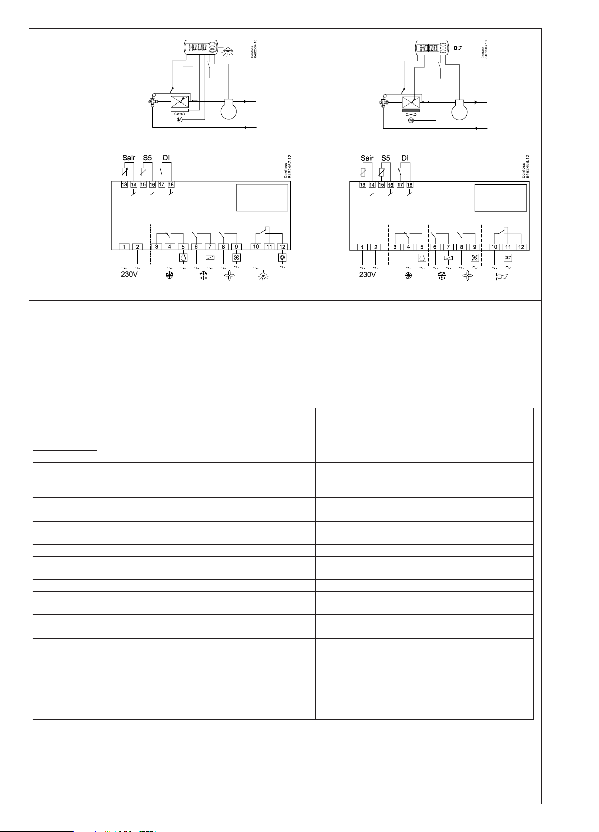
230 V a.c.
50/60 Hz
2.0 VA
084R8038
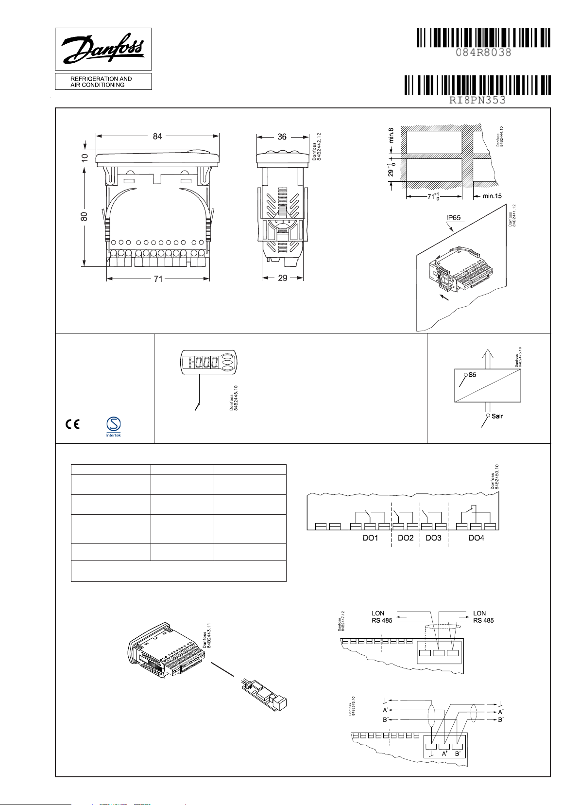
Sensor type = NTC
( Menu = o06)
10 V < U < 256 V
DO1. Refrigeration * 8 (6) A
DO2. Defrost * 8 (6) A
DO3. Fan * 6 (3) A
DO4. Alarm or light *
* DO1 and DO2 are 16 A relays. DO3 and DO4 are 8 A relays. Max. load must be kept.
** Gold plating ensures make function with small contact loads
*** UL-approval based on 30000 couplings
CE (250 V a.c.) UL *** (240 V a.c.)
10 A Resistive
5FLA, 30LRA
10 A Resistive
5FLA, 30LRA
6 A Resistive
3FLA, 18LRA
4 (1) A
Min. 100 mA**
131 VA Pilot duty
4 A Resistive
131 VA Pilot duty
Data communication LON RS 485 / MOD-bus:
LON
MOD-bus
RI8PN353 06-2015
Page 2
*) AU:
*)
Guld, Gold or Oro
l = max. 15 m
Sair, S5=
NTC 5000 Ω @ 25°C, M2020 (Danfoss type=EKS 211) /
NTC 10000 Ω @ 25°C, Beta 3435 (Danfoss type=EKS 221) /
NTC 3000 Ω @ 25°C /
NTC 2500 Ω @ 0°C /
NTC 10000 Ω @ 25°C /
NTC 2000 Ω @ 25°C
*)
Type NTC 5000 Ω
@ 25°C
(M2020)
NTC 10000 Ω
@ 25°C
(Beta 3435)
NTC 3000 Ω
@ 25°C
NTC 2500 Ω
@ 0°C
NTC 10000 Ω
@ 25°C
NTC 2000 Ω
@ 25°C
Danfoss NTC = EKS 211 EKS 221 - - - -
°C Ω Ω Ω Ω Ω Ω
30 4029 8313 2417 - 8300 1651
25 5000 10000 3000 883 10000 2000
20 6246 12091 3747 1074 12271 2437
15 7855 14695 4712 1313 15146 2987
10 9951 17958 5970 1616 18809 3682
5 12696 22068 7617 2000 23504 4571
0 16330 27278 9798 2492 29564 5716
−5 21166 33922 12700 3124 37441 7198
−10 27681 42450 16608 3947 47754 9133
−15 36503 53468 21902 5019 61357 11644
−20 48614 67801 29168 6434 79440 14961
−25 65333 86580 39200 8306 103676 19402
−30 88766 111364 53259 10822 136428 25388
−35 121795 144324 73077 14217 181078 33505
−40 169157 188500 101490 18848 242495 44657
Alternativer
Alternatives
Alternativen
Alternatives
Alternativas
Carel:
HP/WF/WP/INF
Dixell:
NS/NG/NX/NY/NT
Eliwell:
SN8
Lae:
SN4K..P
Frigo:
M841
Wurm:
TRK 277
Wurm:
T2000
Lae:
SN2K..P
o06 n01 n02 n03 n04 n05 n06
2 Instructions RI8PN353 © Danfoss 06/2015 EKC 202C-MS
Page 3

The buttons
English
Set menu
1. Push the upper button until a parameter
is shown
2. Push the upper or the lower button and
nd that parameter you want to change
3. Push the middle button until the
parameter value is shown
4. Push the upper or the lower button and
select the new value
5. Push the middle button again to enter
the value.
Set temperature
1. Push the middle button until the
temperature value is shown
2. Push the upper or the lower button and
select the new value
3. Push the middle button to select the
setting.
Reading the temperature at sensor S5
• Push briey the lower button
Manual start or stop of a defrost
• Push the lower button for four
seconds.
Light Emitting Diode
= refrigeration
= defrost
= fan running
Flashes fast at alarm
Cutout alarm relay / see alarm code
• Push briey the upper button
Start-up:
Regulation starts when the voltage is on.
1 Go through the survey of factory settings. Make any necessary changes in the respective parameters.
2 For network. Set the address in o03 and then transmit it to the gateway/system unit with setting o04.
Function Codes
Normal operation
Temperature (set point) --- -50°C 50°C 2°C
Thermostat
Dierential r01 0,1 K 20 K 2 K
Max. limitation of setpoint setting r02 -49°C 50°C 50°C
Min. limitation of setpoint setting r03 -50°C 49°C -50°C
Adjustment of temperature indication r04 -20 K 20 K 0.0 K
Temperature unit (°C/°F) r05 °C °F °C
Correction of the signal from Sair r09 -10 K 10 K 0 K
Manual service(-1), stop regulation(0), start regulation (1) r12 -1 1 1
Displacement of reference during night operation r13 -10 K 10 K 0 K
Activation of reference displacement r40 r39 OFF on OFF
Value of reference displacement (can be activated by r39 or DI) r40 -50 K 50 K 0 K
Alarm
Delay for temperature alarm A03 0 min 240 min 30 min
Delay for door alarm A04 0 min 240 min 60 min
Delay for temperature alarm after defrost A12 0 min 240 min 90 min
High alarm limit A13 -50°C 50°C 8°C
Low alarm limit A14 -50°C 50°C -30°C
Alarm delay DI1 A27 0 min 240 min 30 min
High alarm limit for condenser temperature (o70) A37 0°C 99°C 50°C
Compressor
Min. ON-time c01 0 min 30 min 0 min
Min. OFF-time c02 0 min 30 min 0 min
Compressor relay must cutin and out inversely (NC-function) c30 0 / OFF 1 / on 0 / OFF
Defrost
Defrost method (none/EL/gas) d01 no gas EL
Defrost stop temperature d02 0°C 25°C 6°C
Interval between defrost starts d03 0 hours 240 hours 8 hours
Max. defrost duration d04 0 min 180 min 45 min
Displacement of time on cutin of defrost at start-up d05 0 min 240 min 0 min
Drip o time d06 0 min 60 min 0 min
Delay for fan start after defrost d07 0 min 60 min 0 min
Fan start temperature d08 -15°C 0°C -5°C
Fan cutin during defrost
0: Stopped
1: Running
2: Running during pump down and defrost
Defrost sensor (0=time, 1=S5, 2=Sair) d10 0 2 0
Max. aggregate refrigeration time between two defrosts d18 0 hours 48 hours 0 hours
Defrost on demand - S5 temperature’s permitted variation during frost build-up. On central plant choose
20 K (=o)
Fans
Fan stop at cutout compressor F01 no yes no
Delay of fan stop F02 0 min 30 min 0 min
Fan stop temperature (S5) F04 -50°C 50°C 50°C
Real time clock
Six start times for defrost.
Setting of hours.
0=OFF
Six start times for defrost.
Setting of minutes.
0=OFF
Clock - Setting of hours t07 0 hours 23 hours 0 hours
Clock - Setting of minute t08 0 min 59 min 0 min
Clock - Setting of date t45 1 31 1
Clock - Setting of month t46 1 12 1
Clock - Setting of year t47 0 99 0
Parameters
t01-t06 0 hours 23 hours 0 hours
t11-t16 0 min 59 min 0 min
Min.-value Max.-value
d09 0 2 1
d19 0 K 20 K 20 K
Factory
setting
SW = 1.3x
Actual set-
ting
EKC 202C-MS Instructions RI8PN353 © Danfoss 06/2015 5
Page 4

Miscellaneous
Delay of output signals after start-up o01 0 s 600 s 5 s
Input signal on DI1. Function:
0=not used. 1=status on DI1. 2=door function with alarm when open. 3=door alarm when open. 4=defrost
start (pulse-signal). 5=ext.main switch. 6=night operation 7=change reference (activate r40). 8=alarm function when closed. 9=alarm function when open. 10=case cleaning (pulse signal). 11=Inject o when open.
Network address o03 0 119 0
On/O switch (Service Pin message) o04 OFF ON OFF
Access code 1 (all settings) o05 0 100 0
Used sensor type:
n01: NTC 5000 Ω @ 25°C, M20202 (Danfoss type=EKS 211)
n02: NTC 10000 Ω @ 25°C, Beta 3435 (Danfoss type= EKS 221)
n03: NTC 3000 Ω @ 25°C
n04: NTC 2500 Ω @ 0°C
n05: NTC 10000 Ω @ 25°C
n06: NTC 2000 Ω @ 25°C
Display step = 0.5 (normal 0.1 at Pt sensor) o15 no yes no
Max hold time after coordinated defrost o16 0 min 60 min 20
Conguration of light function (relay 4)
1=ON during day operation. 2=ON / OFF via data communication. 3=ON follows the DI-function, when DI is
selected to door function or to door alarm
Activation of light relay (only if o38=2) o39 OFF ON OFF
Case cleaning. 0=no case cleaning. 1=Fans only. 2=All output O. o46 0 2 0
Access code 2 (partly access) o64 0 100 0
Save the controllers present settings to the programming key. Select your own number. o65 0 25 0
Load a set of settings from the programming key (previously saved via o65 function) o66 0 25 0
Replace the controllers factory settings with the present settings o67 OFF On OFF
Select application for S5 sensor (0=defrost sensor, 1= product sensor, 2=condenser sensor with alarm) o70 0 2 0
Select application for relay 4: 1=light, 2= alarm o72 1 2 2
Service
Temperature measured with S5 sensor u09
Status on DI1 input. on/1=closed u10
Status on night operation (on or o) 1=closed u13
Read the present regulation reference u28
Status on relay for cooling (Can be controlled manually, but only when r12=-1) u58
Status on relay for fans (Can be controlled manually, but only when r12=-1) u59
Status on relay for defrost. (Can be controlled manually, but only when r12=-1) u60
Temperature measured with Sair sensor u69
Status on relay 4 (alarm, light).(Can be controlled manually, but only when r12=-1) u71
o02 0 11 0
o06 n01 n06 n02
o38 1 3 1
Factory setting
If you need to return to the factory-set values, it can be done in this way:
- Cut out the supply voltage to the controller
- Keep upper and lower button depressed at the same time as you recon nect the supply voltage
Fault code display Alarm code display Status code display
E1 Fault in controller A 1 High temperature alarm S0 Regulating
E6 Change battery + check clock A 2 Low temperature alarm S1 Waiting for end of the coordinated defrost
E 27 S5 sensor error A 4 Door alarm S2 ON-time Compressor
E 29 Sair sensor error A 5 Max. Hold time S3 OFF-time Compressor
A 15 DI 1 alarm S4 Drip-o time
A 45 Standby mode S10 Refrigeration stopped by main switch
A 59 Case cleaning S11 Refrigeration stopped by thermostat
A 61 Condenser alarm S14 Defrost sequence. Defrosting
S15 Defrost sequence. Fan delay
S16 Refrigeration stopped because of open DI
input
S17 Door open (open DI input)
S20 Emergency cooling
S25 Manual control of outputs
S29 Case cleaning
S32 Delay of output at start-up
non The defrost temperature cannot be dis-
played. There is stop based on time
-d- Defrost in progress / First cooling after
defrost
PS Password required. Set password
6 Instructions RI8PN353 © Danfoss 06/2015 EKC 202C-MS
 Loading...