

Page 1
Data sheet
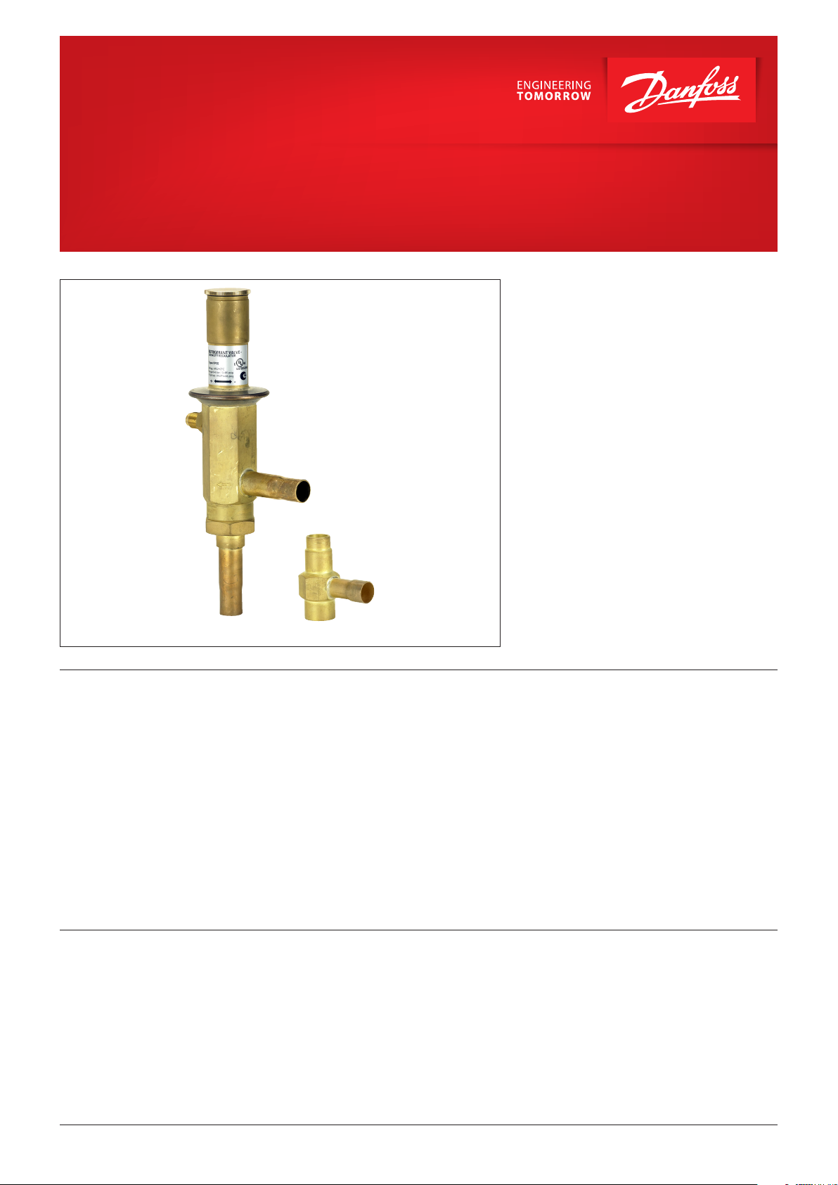
Hot gas bypass regulator, type CPCE
Liquid gas mixer, type LG (accessory)
CPCE hot gas bypass regulator adapt compressor
capacity to actual evaporator load.
They are designed for installation in a bypass line
between the low and high pressure sides of the
refrigeration system, for hot gas injection
between the evaporator and thermostatic
expansion valve.
Injection should be arranged to occur through
an LG liquid gas mixer.
Features
Approvals UL listed, file SA7200
CPCE hot gas bypass regulator
• Superior control accuracy
• Direct connection to system suction line
regulates hot gas injection independent
of evaporator pressure drop
• The regulator increases evaporator gas
velocity, thus ensuring better oil return to
compressor
• Protection against too low an evaporating
temperature, i.e. prevents evaporator icing
• May be used in the following EX range:
Category 3 (Zone 2)
LG liquid gas mixer
• LG provides homogeneous mixing of the
liquid and hot gas refrigerant injected into the
evaporator
• Prevents high suction superheat by combining
hot gas injection with expansion valve
characteristics
• LG can be used for hot gas defrosting or
reverse cycle systems
© Danfoss | DCS (az) | 2018.11 DKRCC.PD.HF0.4B.02 | 1
Page 2
Data sheet | Hot gas bypass regulator type CPCE, Liquid gas mixer type LG (accessory)
Technical data
Refrigerants
Regulating range
Maximum working pressure
Maximum test pressure
Maximum differential pressure
Maximum media temperature
Minimum media temperature -50 °C
This product is evaluated for R290, R600, R600a,
R1234ze, R1270 by ignition source assessment in
accordance with standard EN13463-1.
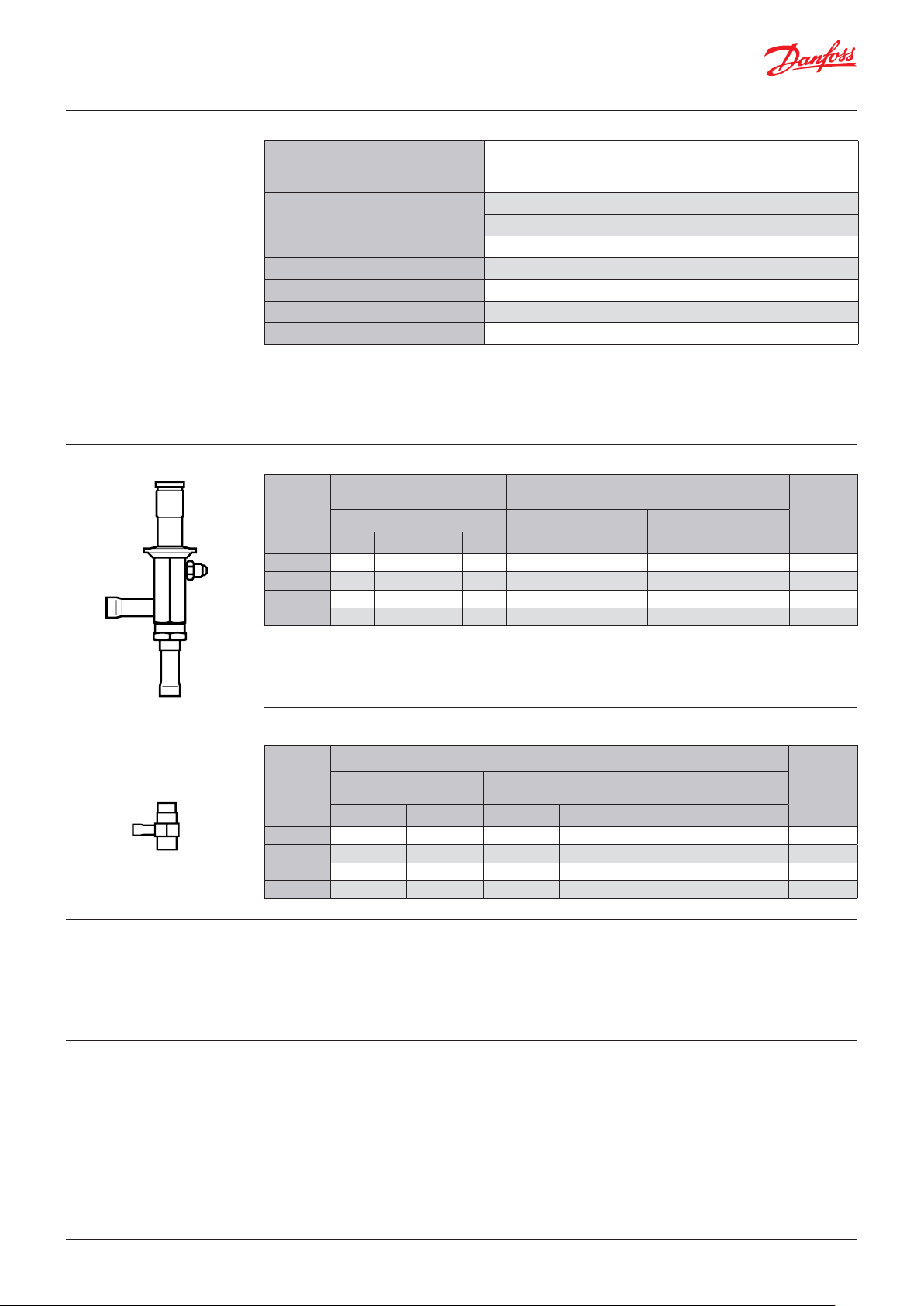
Ordering Hot gas bypass regulator
Connection
Typ e
CPCE 12
CPCE 12 – –
CPCE 15
CPCE 22 –
1)
The rated capacity is the regulator capacity at:
- evaporating temperature t
- condensing temperature tc = 30 °C,
- reduction of suction temperature / suction pressure ∆ts = 4 K.
Flare
[in]
1
/
2
– –
[mm] [in]
12 –
–
= -10 °C,
e
R22, R1234ze *), R1270 *), R134a, R290 *), R404A, R407A, R407C, R407F,
R448A, R449A, R450A, R452A, R507A, R513A, R600 *), R600a *)
*) only LG 12-16 and LG 16-22
p
= 0 – 6 bar
e
Factory setting = 0.4 bar
PS/MWP = 28 bar
Pe = 31 bar
Δp = 18 bar
140 °C
For complete list of approved refrigerants,
visit www.products.danfoss.com and search for
individual code numbers, where refrigerants are
listed as part of technical data.
Rated capacity 1)
[kW]
Solder
[mm]
–
1
/
12 17.4 7.9 16.4 19.0 034N0082
2
5
/
16
8
7
/
22 34.0
8
R22
R134a
17.4 7.9
25.6 11. 6
15. 2
R404A/
R507
16.4 19.0
24.2
32.0 3 7.1
R407C
27. 9 034N0083
Code no.
034N0081
034N0084
REACH requirements
Sizing
Liquid gas mixer
[in]
5/
7/
8
8
8
8
Outlet
ODM
[mm] [in]
16
22
28
35
1
/
2
1
/
2
5
/
8
7
/
8
Typ e
LG 12 – 16
LG 12 – 22
LG 16 – 28 1 1/
LG 22 – 35 1 3/
All Danfoss products fulfill the requirements in
REACH.
One of the obligations in REACH is to inform
customers about presence of Candidate list
substances if any, we hereby inform you about
one substance on the candidate list:
For optimum performance, it is important
to select a CPCE valve according to system
conditions and application.
The following data must be used when sizing
a CPCE valve:
y Refrigerant: HCFC, HFC and HC
y Minimum suction temperature: ts in [°C] / [bar]
y Compressor capacity at minimum suction
temperature: Q
in [kW]
1
Connection
Inlet hot gas
ODF
Inlet liquid
ODF
[mm] [in]
12 5/
12 7/
16 1 1/
22 1
8
8
8
3
/
8
an O-ring used in this product contains
Diisopentyl phthalate (CAS no: 605-50-5) in a
concentration above 0.1% w/w.
y Evaporator load at minimum suction
temperature: Q2 in [kW]
y Liquid temperature ahead of expansion valve:
t
[°C]
l
y Reduction of suction temperature/suction
pressure in [K]
y Connection type: flare or solder
y Connection size in [in] or [mm]
Code no.
[mm]
16 069 G4 001
22 069G4002
28 069G4003
35 069G4004
© Danfoss | DCS (az) | 2018.11
DKRCC.PD.HF0.4B.02 | 2
Page 3
Data sheet | Hot gas bypass regulator type CPCE, Liquid gas mixer type LG (accessory)
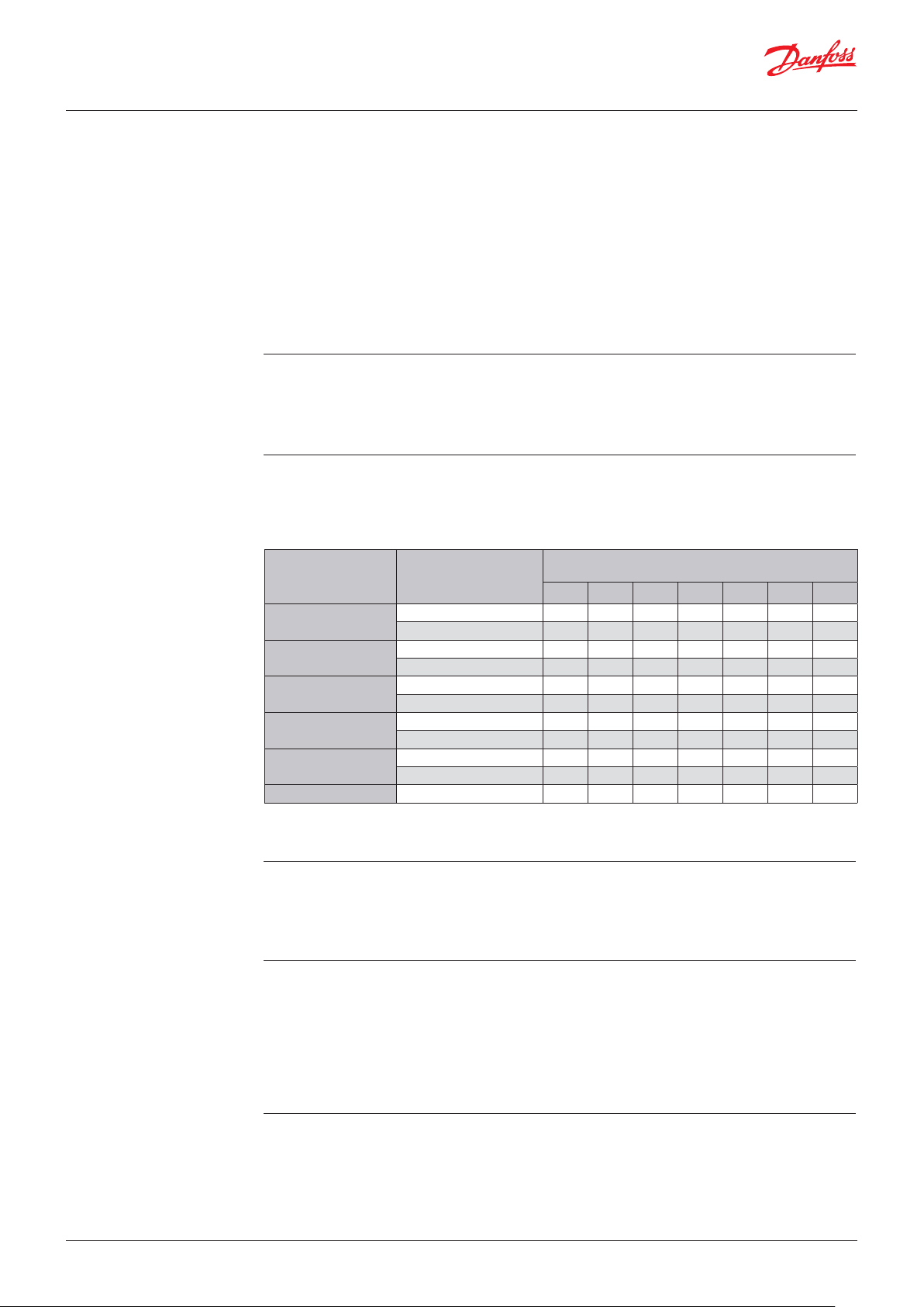
Selection
Example
When selecting the appropriate valve it may be
necessary to convert the actual capacity using a
correction factor. This is required when system
conditions are different from table conditions.
Step 1
Determine the replacement capacity. This is done
by taking the compressor capacity at minimum
suction temperature Q1 minus evaporator load at
Step 2
Determine the correction factor for the reduction
of suction temperature / suction pressure.
Suction temp. t
after reduction
[°C]
10
-10
-20
-30
-40 R22, R404A, R507, R407C 0 .1 0.3 0.6 1.0 1.5 2.0 2.2
s
0
Refrigerant
R134a 0.1 0.5
R22, R404A, R507, R407C 0.3 0.9 1.0 1.0 1.0 1.0 1.0
R134a 0.1 0.3
R22, R404A, R507, R407C 0.2
R134a 0.1 0.3 0.6 1.0 1.3 1.4 1.4
R22, R404A, R507, R407C 0.1 0.5
R134a 0.1 0.3 0.6
R22, R404A, R507, R407C 0.1 0.3 0.7 1.0 1.0 1. 0 1.0
R134a 0.1 0.3 0.6 1.0 1.5 2.2 2.9
R22, R404A, R507, R407C 0.1 0.3 0.6 1.0 1.3 1.4 1.4
The correction table is used when suction
temperature change deviates from 4 K.
The following examples illustrate how this is
done.
y Refrigerant: R404A
y Minimum suction temperature: t
y Compressor capacity at -30 °C, Q
= -30 °C
s
= 80 kW
1
y Evaporator load at -30 °C, Q2 = 60 kW
y Liquid temperature ahead of expansion valve:
t
= 40 °C
l
y Reduction of suction temperature/suction
pressure = 5 K
y Connection type: solder
y Connection size = 1/
in
2
minimum suction temperature Q2.
Q
- Q
=80-60=20 kW
1
2
From the correction factor table (see below)
a suction temperature reduction of 5 K (R404A)
corresponds to a factor of 1.3.
Suction temperature ∆t
1
2
3 4
0.9 1.0 1.0
0.7 1.0 1.0
0.9 1.0 1.0 1.0
1.0 1.0 1.0 1.0
[K]
1.0 1.5 2.2
s
5 6
1.0 1.0
1.0 1.0
1.0 1.0
The replacement capacity must be divided
by the correction factor determined.
7
1.0
2.4
© Danfoss | DCS (az) | 2018.11
Step 3
Corrected replacement capacity is
Q=20/1.3=15.4 kW
Step 4
Now select the appropriate capacity table for
R404A and choose the column with a suction
temperature of ts = -30 °C.
Step 5
CPCE 12, 1/2 in solder connection,
code no. 034N0082 (see Ordering).
Using the corrected replacement capacity, select
a valve that provides an equivalent or greater
capacity.
A CPCE 12 delivers a replacement capacity of
17.9 kW at a minimum suction temperature of
-30 °C.
DKRCC.PD.HF0.4B.02 | 3
Page 4

Data sheet | Hot gas bypass regulator type CPCE, Liquid gas mixer type LG (accessory)
Capacity
Suction temperature
t
after pressure /
Typ e
s
temperature reduction
[°C]
20
R22
CPCE 12
CPCE 15
CPCE 22
10
0 12. 9 17.3 21.7 2 7.1 33.4
-10
-20
-30 8.0 11. 0 14.7 18.6 33.4
-40
10
0 18.8 25.4 32.0 39.9 49.0
-10 20.0
-20
-30 11. 5 16 .0 21.2 27.1 49.0
-40 5.9
10 15. 2
0 25.0 33.6 42.4 52.8 64.9
-10
-20 26.6
-30 15.4 21.3 28 .1 35.9 64.9
-40 8.0 10.7 14.3 – 64.9
7.9 16.3
13. 6
13. 7 17.6
4.3
11. 5
20.1
26.5 34.0
R134a
10 2.3 10.4 14.4 18 .0 22.6
0 7.8 11. 3 14.4 18.1 22.6
CPCE 12
CPCE 15
CPCE 22
The capacities are determined by reducing the
suction temperature/suction pressure at
∆ts = 4 K. The given suction temperatures are
minimum values, i.e. after reduction.
-10 5.8 7.9 10. 8 14.4 18 .1
-20 3.4 4.6 6.1 8.3 10.6
-30 2.0 2.8 3.7 4.9 6.2
10 2.3 15.2 21.1 26.5 33.2
0 11.4 16.6 21.2 26.6 33.2
-10 8.3 11.6 15.7 21.1 26.6
-20 4.8 6.6 8.8 11.9 15 . 2
-30 2.6 3.5 4.9 6.4 8.0
10 3.1 20.4 28.0 35.2 43.9
0 15.1 22.8 28.1 35.2 43.9
-10 10 .9 15. 2 20.9 2 7.7 35.2
-20 6.4 8.8 11 . 8 15.7 20.3
-30 3.7 5.0 6.8 8.9 11. 3
Regulator capacity Q [kW]
at condensing temperature tc [°C]
30
17.4 22.0
5.7 7.6
24.0 31.7
25.6 32.3
25.8 32.6
7.8
31.7
34.2
40
21.6 26.9
22.2
10.6 –
42.0 52.3
42.8 53.4
43.1 53.8
50
27. 4 33.4
27. 7 33.4
– 33.4
39.4 49.0
40.2
40.7 49.0
60
33.4
49.0
49.0
64.9
64.9
64.9
The capacities are made up of the CPCE hot
gas capacity + the extra capacity given by
the thermostatic expansion valve to keep the
superheat constant after the evaporator.
© Danfoss | DCS (az) | 2018.11
DKRCC.PD.HF0.4B.02 | 4
Page 5

Data sheet | Hot gas bypass regulator type CPCE, Liquid gas mixer type LG (accessory)
Capacity
(continued)
Suction temperature
t
after pressure /
Typ e
s
temperature reduction
[°C]
20
R404A/R507
CPCE 12
CPCE 15
CPCE 22
10
0 12 . 2 16.4 20.6 25.7 31.1
-10
-20
-30 10. 3 13.8 17. 9 – 31.1
-40
10
0 18 .0 24. 2 30.3 37. 8 46.9
-10 19.1
-20
-30 15.0 20.3 26.5 – 46.9
-40 8.0
10 14.6
0 23.8 32.0 40 .1 49.9 62.3
-10
-20 25.3
-30 19.9 26.7 34.8 – 62.3
-40 10.6 14.2 18.0 – 62.3
7.5 15.5
12. 9
13.1 16 .4
5.5
11. 0
19.1
25.3 32.0
R407C
10 9.7 18. 3 23.5 28.2 33.4
0 14 .4 19.0 23.2 2 7. 9 33.4
CPCE 12
CPCE 15
CPCE 22
The capacities are determined by reducing the
suction temperature/suction pressure at
∆ts = 4 K. The given suction temperatures are
minimum values, i.e. after reduction.
-10 15.1 19. 0 23.3 27. 4 33.4
-20 15.1 18.8 23 .1 27.4 33.4
-30 8.7 11.7 15 .0 18 .0 33.4
-40 4.6 5.9 7.6 – 33.4
10 14.1 26.9 34.6 41.4 49.0
0 21.1 27. 9 34.2 41.1 49.0
-10 22.2 2 7.9 34.2 40.2 49.0
-20 22 .1 27.6 33.9 40.3 49.0
-30 12.5 17. 0 21.6 26.3 49.0
-40 6.3 8.1 10. 6 – 49.0
10 18.7 35.5 45.8 54.9 64.9
0 28.0 37. 0 45.4 54.4 64.9
-10 29.4 37.1 45.4 53.4 64.9
-20 29.3 36.6 44.8 53.3 64.9
-30 16.8 22.6 28.7 34.8 64.9
-40 8.6 11.1 14 .3 – 64.9
Regulator capacity Q [kW]
at condensing temperature tc [°C]
30
16.4 20.7
7.5 9.5
22.8 30.3
24.2 30.4
24.3 30.4
10.6
30.2
32.1
40
20.6 25.7
20.7
13. 4 –
40 .1 49.9
40 .1 50.0
40.2 –
50
25.7 31.1
– 31.1
– 31.1
37. 8 46.9
37. 8
– 46.9
60
31.1
46.9
46.9
62.3
62.3
62.3
The capacities are made up of the CPCE hot
gas capacity + the extra capacity given by the
thermostatic expansion valve to maintain the
superheat after of the evaporator constant.
© Danfoss | DCS (az) | 2018.11
DKRCC.PD.HF0.4B.02 | 5
Page 6

4
69G39.12.10
1
2
3
Data sheet | Hot gas bypass regulator type CPCE, Liquid gas mixer type LG (accessory)
Design / Function
1. Inlet
2. Outlet
3. Pilot pressure connection
4. Protective cap
5. Setting screw
6. Main spring
7. Diaphragm
8. Pressure pin
9. Pilot orifice
10. Servo piston
11. Pressure equalising hole
12. Main orifice
CPCE
4
5
5
6
6
7
7
3
3
8
8
9
9
10
10
11
11
1
1
12
12
2
2
Danfoss
34N132.13.10
Hot gas bypass regulator, type CPCE is servooperated.
The diaphragm (7) is actuated on the upper side
by the force developed by the spring (6) and on
the lower side by the pilot pressure from (3).
When the pilot pressure drops below the preset
value, the throttling ball is forced away from the
pilot orifice (9) by the spring which acts via the
pressure pin (8).
The pressure over the servo piston (10) is then
relieved. The differential pressure which is thus
created moves the servo piston up and causes
the regulator to open so that hot gas is able to
flow to the suction side.
When the pilot pressure rises above the setting,
the pilot orifice shuts off the evacuation from
the space over the servo piston. Pressure then
builds up again over the piston via the pressure
equalising hole (11), thus closing the regulator.
LG
1
2
Danfoss
1. Liquid inlet
2. Hot gas inlet
3. Outlet
3
© Danfoss | DCS (az) | 2018.11
DKRCC.PD.HF0.4B.02 | 6
Page 7

Danfoss
Dimensions [mm]
and weights [kg]
CPCE
Danfoss
34N133.13
Typ e
L
1
Net weight
CPCE 12 10 0.9
CPCE 15 12 0.9
CPCE 22
17 0.9
LG
69G40.12
Typ e H H
1
LG 12 – 16 54 22 40 24 0.1
LG 12 – 22 62 26 42 28 0.2
LG 16 – 28 79 35 48 36 0.3
LG 22 – 35 89 40 66 41 0.4
L
1
NV Net weight
© Danfoss | DCS (az) | 2018.11
DKRCC.PD.HF0.4B.02 | 7
 Loading...