

Page 1
Instructions
AK-CC 550
115 V
Identication
Principle
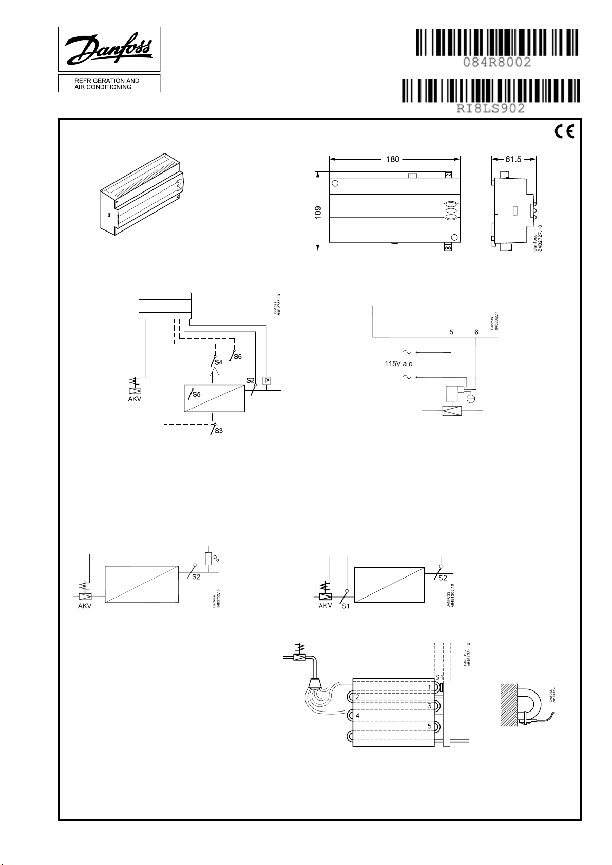
Dimensions
084B8024
AKV:
115 V a.c. coil
115 V c.a. Bobine
Selection of signal to superheat measurement. Pressure transmitter or temperature sensor S1
S1, S2:
Insulate sensors
Sensores aislados
Place S1 on the rst U-bend of the second-lowest evaporator passage
Montar S1 en la primera curva en U del serpentín correspondiente a la penúltima
tubería del distribuidor
RI8LS902 06-2015
Page 2
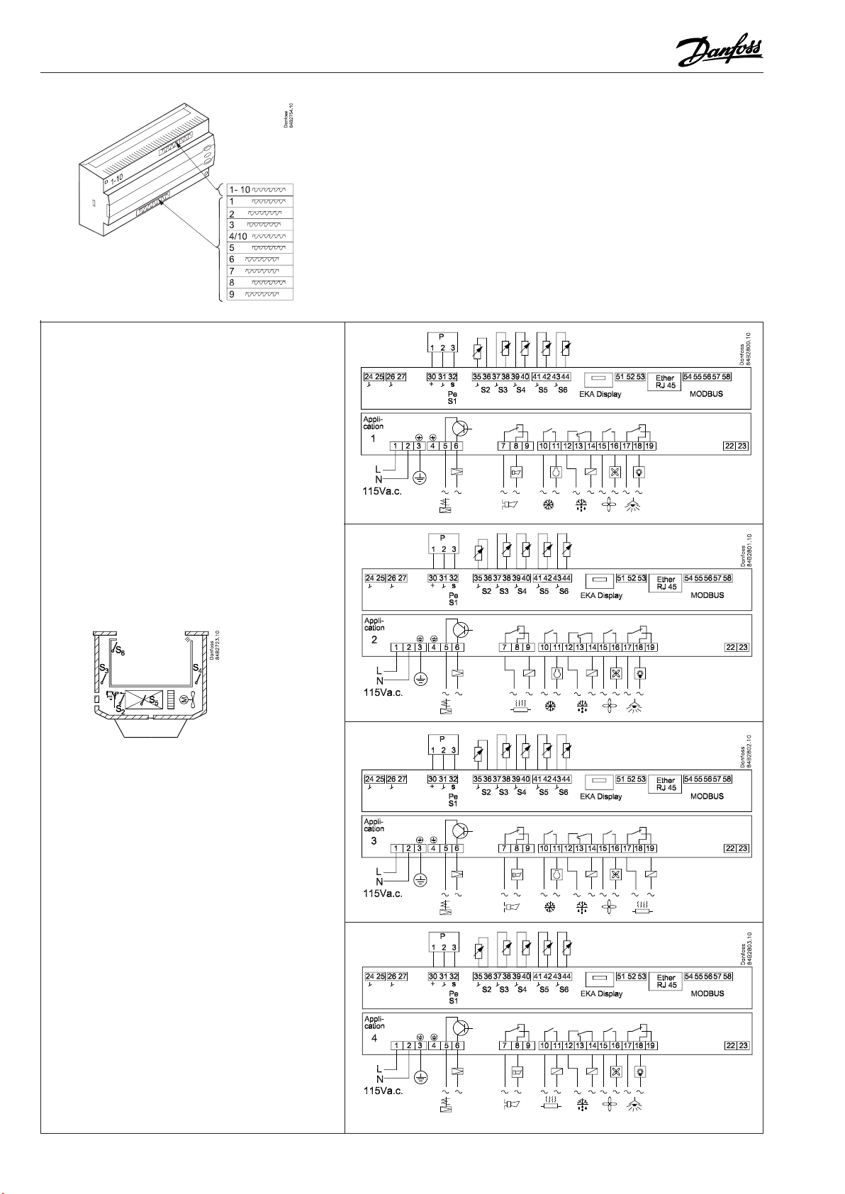
The controller is provided with signs from the factory indicating application 1.
If you employ another use, signs are provided so that you can mount the relevant one.
1
1 - 8
2
3
4
2 Instructions RI8LS902 © Danfoss 06/2015 AK-CC 550 - 115 V
Page 3
5
6
7
9
8
9
10
10
AK-CC 550 - 115 V Instructions RI8LS902 © Danfoss 06/2015 3
Page 4
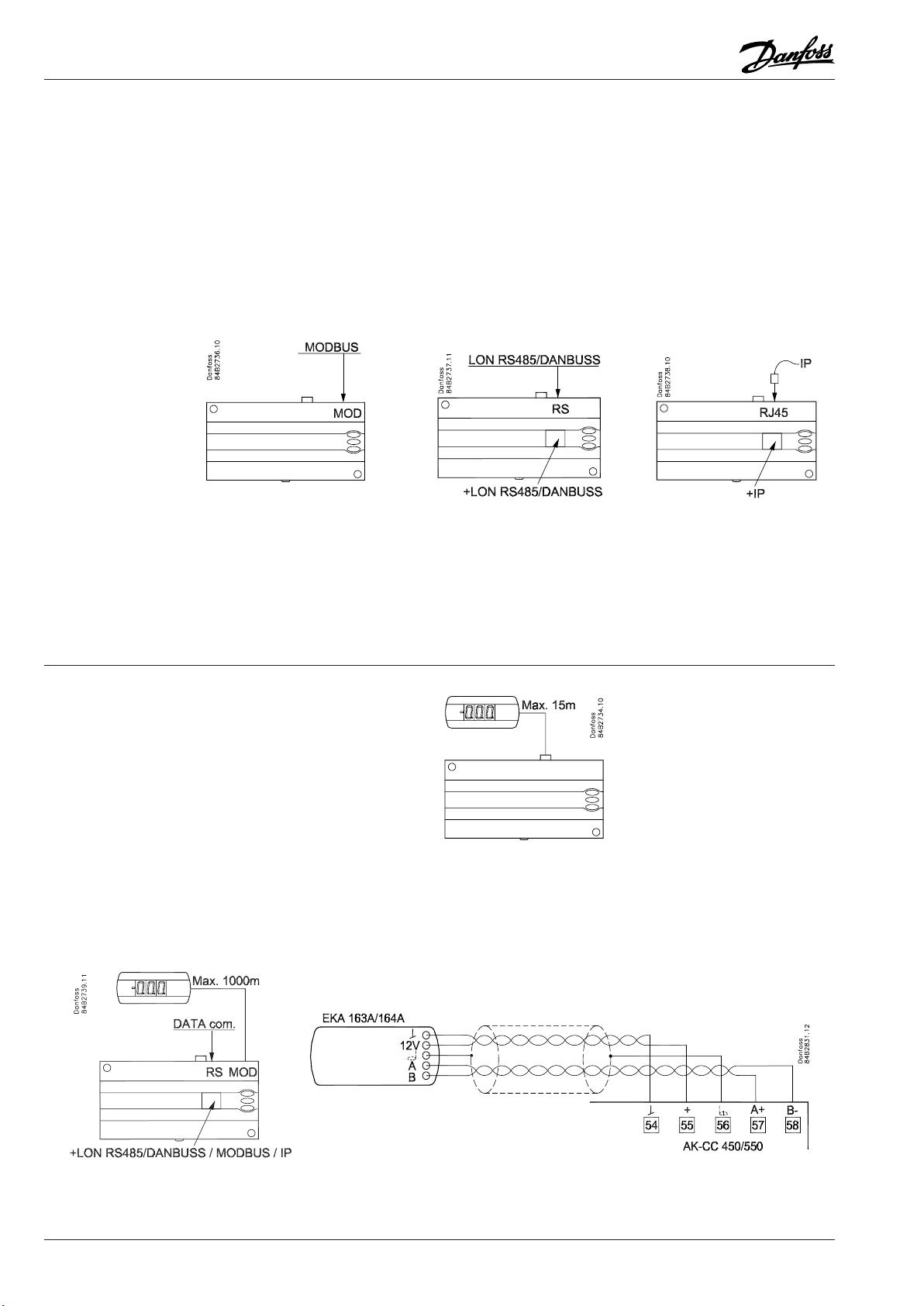
Data communication
Important All connections to the data communication MODBUS and RS 485 must comply
with the requirements for data communication cables. See literature: RC8AC.
System manager
/ Gateway
Display EKA 163 / 164
L < 15 m
L > 15 m
AK-SM.... AKA 245 version 6.20+ /
AK-SM...
OEM
Address o03 > 0
4 Instructions RI8LS902 © Danfoss 06/2015 AK-CC 550 - 115 V
Page 5

Connections
English
Overview of outputs and
applications.
See also electrical diagrams earlier
in the instruction
DI1
Digital input signal.
The dened function is active when the input is short-circuited/
opened. The function is dened in o02.
DI2
Digital input signal.
The dened function is active when the input is short-circuited/
opened. The function is dened in o37.
Pressure transmitter or temperature sensor S1
Pe / AKS 32R (pressure measurement recommended)
Connect to terminal 30, 31 and 32.
The signal from one pressure transmitter can be received by up
to 10 controllers. But only if there are no signicant pressure
decreases between the evaporators to be controlled.
If use with 060G1034 cable, 1=black, 2=blue, 3=brown
S1 (correct location is important to ensure correct measurements)
Pt 1000 ohm sensor
Connect to terminal 31 and 32.
S2
Pt 1000 ohm sensor
S3, S4, S5, S6
Pt 1000 ohm sensor or PTC 1000 ohm sensor. All have to be of
the same type.
S3, air sensor, placed in the warm air before the evaporator
S4, air sensor, placed in the cold air after the evaporator
(the need for either S3 or S4 can be deselected in the
conguration)
S5, defrost sensor, placed on the evaporator
S6, product sensor or defrost sensor B or air sensor B.
The conguration determines which.
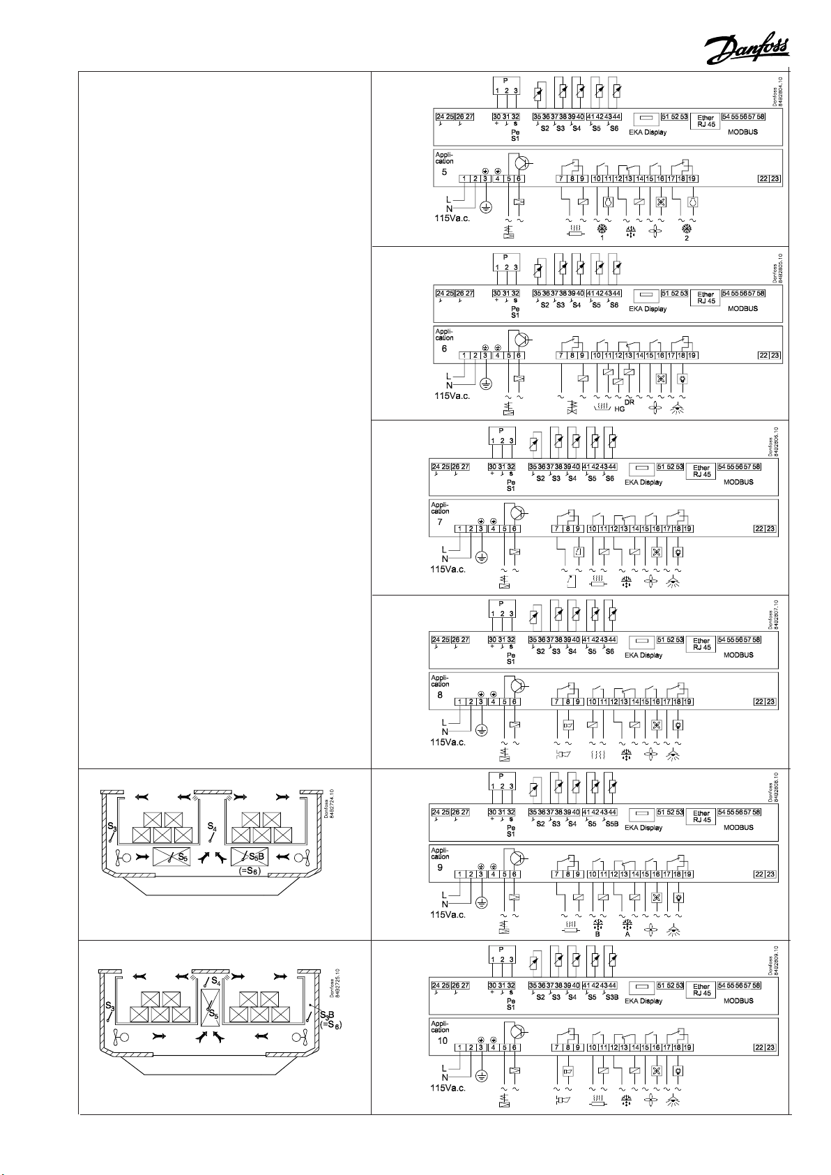
Application DO1 DO2 DO3 DO4 DO5 DO6 DI1 DI2 DI3 AI1 AI2 AI3 AI4 AI5 AI6
1
2
3
4
5
6
7
8
9
10
• • •
• • •
• • •
• • •
• • •
suction
Blinds
heat
hotgas
2 1
• • •
• • •
• • •
• • •
• • •
EKA Display
If there is be external reading/operation of the controller, display
type EKA 163B or EKA 164B can be connected.
RS485 (terminal 51, 52, 53)
For data communication, but only if a data communication
module is inserted in the controller. The module can be a LON
RS485 or a MODBUS.
Terminal 51 = screen
Terminal 52 = A (A+)
Terminal 53 = B (B-)
(For LON RS485 and gateway type AKA 245 the gateway must be
version 6.20 or higher.)
RJ45
For data communication, but only if a TCP/IP module is inserted in
the controller. (OEM)
MODBUS
For data communication.
Terminal 56 = screen
Terminal 57 = A+
Terminal 58 = B(Alternatively the terminals can be connected to an external
display type EKA 163A or 164A, but then they cannot be used
for data communication. Any data communication must then be
carried out by one of the other methods.)
Supply voltage
115 V a.c., 50/60 Hz
P0/S1 S2 S3 S4 S5 S6
P0/S1 S2 S3 S4 S5 S6
P0/S1 S2 S3 S4 S5 S6
P0/S1 S2 S3 S4 S5 S6
P0/S1 S2 S3 S4 S5 S6
P0/S1 S2 S3 S4 S5 S6
P0/S1 S2 S3 S4 S5 S6
P0/S1 S2 S3 S4 S5 S6
P0/S1 S2 S3 S4 S5 S5B
P0/S1 S2 S3 S4 S5 S3B
AK-CC 550 - 115 V Instructions RI8LS902 © Danfoss 06/2015 5
Page 6

DO1
Connection of expansion valve type AKV or AKVA. The coil must
be a 115 V a.c. coil.
DO2
Alarm
There is a connection between terminal 7 and 8 in alarm
situations and when the controller is without power.
Rail heat and heating element in drip tray
There is connection between terminal 7 and 9 when heating
takes place.
Night blind
There is connection between terminal 7 and 9 when the night
blind is up.
Suction line valve
There is connection between terminal 7 and 9 when the
suction line must be open.
DO6
Light relay
There is connection between terminal 17 and 18 when the
light must be on.
Rail heat, Compressor 2
There is connection between terminal 17 and 19 when the
function must be active.
DI3
Digital indput signal.
The signal must have a voltage of 0 / 115 V AC.
The function is dened in o84.
Data communication
If data communication is used, it is important that the installation
of the data communication cable is performed correctly.
See separate literature No. RC8AC…
DO3
Refrigeration, Rail heat, Heat function, Defrost 2
There is connection between terminal 10 and 11 when the
function must be active.
Heating element in drip tray
There is connection between terminal 10 and 11 when heating
takes place.
DO4
Defrost
There is connection between terminal 12 and 14 when
defrosting takes place.
Hot gas / drain valve
There is connection between terminal 13 and 14 during normal
operation.
There is connection between terminal 12 and 14 when the hot
gas valves must open.
DO5
Fan
There is connection between terminal 15 and 16 when the fan
is on.
Coordinated defrost via
cable connections
Electric noise
Cables for sensors, DI inputs and data communication must be
kept separate from other electric cables:
- Use separate cable trays
- Keep a distance between cables of at least 10 cm
- Long cables at the DI input should be avoided
Installation considerations
Accidental damage, poor installation, or site conditions, can give
rise to malfunctions of the control system, and ultimately lead to a
plant breakdown.
Every possible safeguard is incorporated into our products to
prevent this. However, a wrong installation, for example, could still
present problems. Electronic controls are no substitute for normal,
good engineering practice.
Danfoss wil not be responsible for any goods, or plant components, damaged as a result of the above defects. It is the installer's
responsibility to check the installation thoroughly, and to t the
necessary safety devices.
Special reference is made to the necessity of signals to the
controller when the compressor is stopped and to the need of
liquid receivers before the compressors.
Your local Danfoss agent will be pleased to assist with further
advice, etc.
Max. 10
The following controllers can be connected
up in this way:
EKC 204A, AK-CC 210, AK-CC 250,
AK-CC 450, AK-CC 550,
Refrigeration is resumed when all
controllers have “released” the signal for
defrost.
Coordinated defrost via
data communication
The setting of controllers to coordinate
their defrosting takes place in the
gateway/system manager.
Refrigeration is resumed when all
controllers have “released” the signal for
defrost.
6 Instructions RI8LS902 © Danfoss 06/2015 AK-CC 550 - 115 V
Page 7

Operation
Display
The values will be shown with three digits, and with a setting you
can determine whether the temperature is to be shown in °C or in
°F.
Light-emitting diodes (LED) on front panel
The LED’s on the front panel will light up when the relevant relay
is activated.
= Refrigeration
= Defrost
= Fan running
The light-emitting diodes will ash when there is an alarm.
In this situation you can download the error code to the display
and cancel/sign for the alarm by giving the top button a brief
push.
The buttons
When you want to change a setting, the upper and the lower
buttons will give you a higher or lower value depending on the
button you are pushing. But before you change the value, you
must have access to the menu. You obtain this by pushing the
upper button for a couple of seconds - you will then enter the column with parameter codes. Find the parameter code you want to
change and push the middle buttons until value for the parameter
is shown. When you have changed the value, save the new value
by once more pushing the middle button.
Examples
Set menu
1. Push the upper button until a parameter r01 is shown
2. Push the upper or the lower button and nd that parameter you
want to change
3. Push the middle button until the parameter value is shown
4. Push the upper or the lower button and select the new value
5. Push the middle button again to freeze the value.
Cutout alarm relay / receipt alarm/see alarm code
• A short press of the upper button
If there are several alarm codes they are found in a rolling stack.
Push the uppermost or lowermost button to scan the rolling
stack.
Get a good start
With the following procedure you can start regulation very quickly:
1 Open parameter r12 and stop the regulation (in a new and not
previously set unit, r12 will already be set to 0 which means
stopped regulation.)
2 Select electrical connection based on the drawings on page 2
and 3
3 Open parameter o61 and set the electric connection number in
it
4 Now select one of the preset settings from the table
Auxillary schedule for
settings (quick-setup)
Preset settings (o62) 1 2 3 4 5 6
Temperature (SP)
Max. temp. setting (r02)
Min. temp. setting (r03)
Sensor signal for thermostat. S4% (r15)
Alarm limit high (A13)
Alarm limit low (A14)
Sensor signal for alarm
funct.S4% (A36)
Interval between defrost
(d03)
Defrost sensor: 0=time,
1=S5, 2=S4 (d10)
DI1 cong. (o02)
Sensor signal for display
view S4% (017)
Note: For applications 9 and 10 the sensor weighting for the S3/S4 sensors is not used for the
thermostat, alarm thermostat and display readings as the sensor uses are predened.
Case Room
Defrost stop on Defrost stop on
time S5 time S5
2°C -2°C -28°C 4°C 0°C -22°C
6°C 4°C -22°C 8°C 5°C -20°C
0°C -4°C -30°C 0°C -2°C -24°C
100% 0%
8°C 6°C -15°C 10°C 8°C -15°C
-5°C -5°C -30°C 0°C 0°C -30°C
0% 100% 0%
6 h 6h 12h 8h 8h 6h
0 1 1 0 1 1
Case cleaning (=10) Door function (=2)
0%
5 Open parameter o62 and set the number for the array of preset-
tings. The few selected settings will now be transferred to the
menu.
6 Open parameter n57 and select method for measuring of
evaporator pressure Pe or S1 (factory setting is Pe pressure
transmitter)
7 If pressure transmitter Pe is used you must select refrigerant via
parameter o30
8 Open parameter r12 and start the regulation
Set temperature
1. Push the middle button until the temperature value is shown
2. Push the upper or the lower button and select the new value
9 Go through the survey of factory settings. The values in the grey
cells are changed according to your choice of settings. Make any
necessary changes in the respective parameters.
3. Push the middle button again to conclude the setting.
10 For network. Set the address in o03
Reading the temperature at defrost sensor (Or product sensor, if
selected in o92.)
• A short press of the lower button
11 Send address to system unit:
• MODBUS: Activate scan function in system unit
• If another data communication card is used in the controller:
Manuel start or stop of a defrost
- LON RS485: Activate the function o04
• Push the lower button for four seconds.
AK-CC 550 - 115 V Instructions RI8LS902 © Danfoss 06/2015 7
Page 8

Menu survey
Parameter EL-diagram page 2 or 3
Function Code 1 2 3 4 5 6 7 8 9 10
Normal operation
Temperature (setpoint) - - - 1 1 1 1 1 1 1 1 1 1 -50°C 50°C 2
Thermostat
Dierential r01 1 1 1 1 1 1 1 1 1 1 0.1 K 20 K 2
Max. limitation of setpoint setting
Min. limitation of setpoint setting
Adjustment of temperature indication
Temperature unit (°C/°F)
Correction of the signal from S4
Correction of the signal from S3
Manual service, stop regulation, start regulation (-1, 0, 1)
Displacement of reference during night operation
Dene thermostat function
1=ON/OFF, 2=Modulating
Denition and weighting, if applicable, of thermostat sen-
sors - S4% (100%=S4, 0%=S3)
Time between melt periods
Duration of melt periods
Temperature setting for thermostat band 2 . As dierential
r02 1 1 1 1 1 1 1 1 1 1 -49°C 50°C 50
r03 1 1 1 1 1 1 1 1 1 1 -50°C 49°C -50
r04 1 1 1 1 1 1 1 1 1 1 -10 10 0
r05 1 1 1 1 1 1 1 1 1 1 0/°C 1/F 0/°C
r09 1 1 1 1 1 1 1 1 1 1 -10 K 10 K 0
r10 1 1 1 1 1 1 1 1 1 1 -10 K 10 K 0
r12 1 1 1 1 1 1 1 1 1 1 -1 1 0
r13 1 1 1 1 1 1 1 1 1 1 -50 K 50 K 0
r14 1 1 1 1 1 1 1 1 1 1 1 2 1
r15 1 1 1 1 1 1 1 1 0 % 100 % 100
r16 1 1 1 1 1 1 1 1 1 1 0 hrs 10 hrs 1
r17 1 1 1 1 1 1 1 1 1 1 0 min. 30 min. 5
r21 1 1 1 1 1 1 1 1 1 1 -50°C 50°C 2
use r01
Correction of the signal from S6 r59 1 1 1 1 1 1 1 1 1 -10 K 10 K 0
Denition and weighting, if applicable, of thermostat sensors when night cover is on. (100%=S4, 0%=S3)
Heat function
r61 1 0 % 100 % 100
r62 1 0 K 50 K 2
Neutral zone between refrigeration and heat function
Time delay at switch between refrigeration and heat
r63 1 0 min. 240 min. 0
function
Alarms
Delay for temperature alarm
Delay for door alarm
Delay for temperature alarm after defrost
High alarm limit for thermostat 1
Low alarm limit for thermostat 1
High alarm limit for thermostat 2
Low alarm limit for thermostat 2
High alarm limit for sensor S6 at thermostat 1
Low alarm limit for sensor S6 at thermostat 1
High alarm limit for sensor S6 at thermostat 2
Low alarm limit for sensor S6 at thermostat 2
S6 alarm time delay
With setting = 240 the S6 alarm will be omitted
Alarm time delay or signal on the DI1 input
Alarm time delay or signal on the DI2 input
Signal for alarm thermostat. S4% (100%=S4, 0%=S3)
A03 1 1 1 1 1 1 1 1 1 1 0 min. 240 min. 30
A04 1 1 1 1 1 1 1 1 1 1 0 min. 240 min. 60
A12 1 1 1 1 1 1 1 1 1 1 0 min. 240 min. 90
A13 1 1 1 1 1 1 1 1 1 1 -50°C 50°C 8
A14 1 1 1 1 1 1 1 1 1 1 -50°C 50°C -30
A20 1 1 1 1 1 1 1 1 1 1 -50°C 50°C 8
A21 1 1 1 1 1 1 1 1 1 1 -50°C 50°C -30
A22 1 1 1 1 1 1 1 1 1 -50°C 50°C 8
A23 1 1 1 1 1 1 1 1 1 -50°C 50°C -30
A24 1 1 1 1 1 1 1 1 1 -50°C 50°C 8
A25 1 1 1 1 1 1 1 1 1 -50°C 50°C -30
A26 1 1 1 1 1 1 1 1 1 0 min. 240 min. 240
A27 1 1 1 1 1 1 1 1 1 1 0 min. 240 min. 30
A28 1 1 1 1 1 1 1 1 1 1 0 min. 240 min. 30
A36 1 1 1 1 1 1 1 1 0 % 100 % 100
Delay for S6 (product sensor alarm) after defrost A52 1 1 1 1 1 1 1 1 1 0 min. 240 min. 90
Compressor
Min. ON-time c01 1 1 1 1 0 min. 30 min. 0
Min. OFF-time c02 1 1 1 1 0 min. 30 min. 0
Time delay for cutin of comp.2
c05 1 0 sec 999 sec 5
Defrost
Defrost method: 0=none, 1= EL, 2= Gas d01 1 1 1 1 1 1 1 1 1 1 0/No 2/GAs 1/EL
Defrost stop temperature
Interval between defrost starts
Max. defrost duration
Displacement of time on cutin of defrost at start-up
Drip o time
Delay for fan start after defrost
Fan start temperature
Fan cutin during defrost
d02 1 1 1 1 1 1 1 1 1 1 0°C 50°C 6
d03 1 1 1 1 1 1 1 1 1 1 0 hrs/O 240 hrs 8
d04 1 1 1 1 1 1 1 1 1 1 0 min. 360 min. 45
d05 1 1 1 1 1 1 1 1 1 1 0 min. 240 min. 0
d06 1 1 1 1 1 1 1 1 1 1 0 min. 60 min. 0
d07 1 1 1 1 1 1 1 1 1 1 0 min. 60 min. 0
d08 1 1 1 1 1 1 1 1 1 1 -50 °C 0 °C -5
d09 1 1 1 1 1 1 1 1 1 1 0 2 1
0: Stopped
1: Running
2: Running during pump down and defrost
Defrost sensor: 0 =Stop on time, 1=S5, 2=S4, 3=Sx
d10 1 1 1 1 1 1 1 1 1 1 0 3 0
(Application 1-8 and 10: both S5 and S6.
Application 9: S5 and S5B)
Min.-value Max.-value
Factory
setting
SW = 1.5x
Actual
setting
8 Instructions RI8LS902 © Danfoss 06/2015 AK-CC 550 - 115 V
Page 9

Continued Code 1 2 3 4 5 6 7 8 9 10 Min. Max. Fac. Actual
Pump down delay
d16 1 1 1 1 1 1 1 1 1 1 0 min. 60 min. 0
Drain delay (used at hot gas defrost only) d17 1 0 min. 60 min. 0
Max. aggregate refrigeration time between two defrosts
Heat in drip tray. Time from defrosting stops to heating
d18 1 1 1 1 1 1 1 1 1 1 0 hrs 48 hrs 0/OFF
d20 1 0 min. 240 min. 30
in the drip tray is switched o
Extra defrost with adaptive function allowed:
d21 1 1 1 1 1 1 1 1 1 1 0 4 0
0=none, 1=monitoring only, 2=Day only, 3=Both day
and night, 4=Night only
Reset of the "Adaptive defrosting function" (starts a
d22 1 1 1 1 1 1 1 1 1 1 0/OFF 1/ON 0/OFF
defrost and starts subsequent new tuning)
Injection control function
Injection algorithm
n05 1 1 1 1 1 1 1 1 1 1 30 sec 600 sec 150
Only for trained personnel
Max. value of superheat reference
Min. value of superheat reference
n09 1 1 1 1 1 1 1 1 1 1 3°C 20°C 12
n10 1 1 1 1 1 1 1 1 1 1 3°C 20°C 3
MOP temperature. O if MOP temp. = 15.0 °C n11 1 1 1 1 1 1 1 1 1 1 -50°C 15°C 15
Glide for Ezotrope refrigerant (at S1-measurement only) n12 1 1 1 1 1 1 1 1 1 1 0 K 10 K 0
Period time of AKV pulsation
Only for trained personnel
Injection algorithm
Only for trained personnel
Injection algorithm
Only for trained personnel
Injection algorithm
Only for trained personnel
Injection algorithm
Only for trained personnel
Injection algorithm
Only for trained personnel
Injection algorithm
Only for trained personnel
Selection of signal to superheat measurement: 1=
n13 1 1 1 1 1 1 1 1 1 1 3 sec 6 sec 6
n15 1 1 1 1 1 1 1 1 1 1 30 sec 600 sec 180
n16 1 1 1 1 1 1 1 1 1 1 10 % 75 % 30
n17 1 1 1 1 1 1 1 1 1 1 5 % 70 % 30
n18 1 1 1 1 1 1 1 1 1 1 0 10 4
n23 1 1 1 1 1 1 1 1 1 1 1 50 6
n24 1 1 1 1 1 1 1 1 1 1 100 sec 1800 sec 900
n57 1 1 1 1 1 1 1 1 1 1 1 2 1
pressure transmitter AKS32R, 2= Temperature sensor S1
Fan
Fan stop temperature (S5)
Pulse operation on fans: 0=No pulse operation, 1=At
F04 1 1 1 1 1 1 1 1 1 1 -50°C 50°C 50
F05 1 1 1 1 1 1 1 1 1 1 0 2 0
thermostat cuts out only, 2= Only at thermostat cut
outs during night operation
Period time for fan pulsation (on-time + o-time) F06 1 1 1 1 1 1 1 1 1 1 1 min. 30 min. 5
On-time in % of period time F07 1 1 1 1 1 1 1 1 1 1 0 % 100 % 100
Real time clock
Six start times for defrost.
Setting of hours.
0=OFF
Six start times for defrost.
Setting of minutes.
0=OFF
Clock - Setting of hours
Clock - Setting of minute
Clock - Setting of date
Clock - Setting of month
Clock - Setting of year
Miscellaneous
Delay of output signals after start-up
Input signal on DI1. Function:
0=not used. 1=status on DI1. 2=door function with alarm
when open. 3=door alarm when open. 4=defrost start
(pulse-signal). 5=ext.main switch. 6=night operation
7=thermostat band changeover (activate r21). 8=alarm
function when closed. 9=alarm function when open.
10=case cleaning (pulse signal). 11=forced cooling at hot
gas defrost, 12=night cover
Network address (0=o)
On/O switch (Service Pin message)
IMPORTANT! o61 must be set prior to o04
t01 -
1 1 1 1 1 1 1 1 1 1 0 hrs 23 hrs 0
t06
t11 -
1 1 1 1 1 1 1 1 1 1 0 min. 59 min. 0
t16
t07 1 1 1 1 1 1 1 1 1 1 0 hrs 23 hrs 0
t08 1 1 1 1 1 1 1 1 1 1 0 min. 59 min. 0
t45 1 1 1 1 1 1 1 1 1 1 1 day 31 day 1
t46 1 1 1 1 1 1 1 1 1 1 1 mon. 12 mon. 1
t47 1 1 1 1 1 1 1 1 1 1 0 year 99 year 0
o01 1 1 1 1 1 1 1 1 1 1 0 sec 600 sec 5
o02 1 1 1 1 1 1 1 1 1 1 0 12 0
o03 1 1 1 1 1 1 1 1 1 1 0 240 0
o04 1 1 1 1 1 1 1 1 1 1 0/O 1/On 0/O
(used at LON 485 only)
Access code 1 (all settings)
Used sensor type : 0=Pt1000, 1=Ptc1000, o06 1 1 1 1 1 1 1 1 1 1 0/Pt 1/Ptc 0/Pt
Max hold time after coordinated defrost
Select signal for display view. S4% (100%=S4, 0%=S3)
Pressure transmitter working range – min. value
Pressure transmitter working range – max. value
o05 1 1 1 1 1 1 1 1 1 1 0 100 0
o16 1 1 1 1 1 1 1 1 1 1 0 min. 360 min. 20
o17 1 1 1 1 1 1 1 1 0 % 100 % 100
o20 1 1 1 1 1 1 1 1 1 1 -1 bar 5 bar -1
o21 1 1 1 1 1 1 1 1 1 1 6 bar 200 bar 12
AK-CC 550 - 115 V Instructions RI8LS902 © Danfoss 06/2015 9
Page 10

Continued Code 1 2 3 4 5 6 7 8 9 10 Min. Max. Fac. Actual
Refrigerant setting:
o30 1 1 1 1 1 1 1 1 1 1 0 31 0
1=R12. 2=R22. 3=R134a. 4=R502. 5=R717. 6=R13.
7=R13b1. 8=R23. 9=R500. 10=R503. 11=R114.
12=R142b. 13=User dened. 14=R32. 15=R227.
16=R401A. 17=R507. 18=R402A. 19=R404A. 20=R407C.
21=R407A. 22=R407B. 23=R410A. 24=R170. 25=R290.
26=R600. 27=R600a. 28=R744. 29=R1270. 30=R417A.
31=R422A.
Input signal on DI2. Function:
(0=not used. 1=status on DI2. 2=door function with alarm
when open. 3=door alarm when open. 4=defrost start
(pulse-signal). 5=ext. main switch 6=night operation
7=thermostat band changeover (activate r21). 8=alarm
function when closed. 9=alarm function when open.
10=case cleaning (pulse signal). 11=forced cooling at hot
gas defrost.). 12=night cover, 13=coordinated defrost)
Conguration of light function: 1=Light follows day /night
o37 1 1 1 1 1 1 1 1 1 1 0 13 0
o38 1 1 1 1 1 1 1 1 1 4 1
operation, 2=Light control via data communication
via ‘o39’, 3=Light control with a DI-input, 4=As "2", but
light switch on and night cover will open if the network
cut out for more than 15 minutes.
Activation of light relay (only if o38=2) On=light o39 1 1 1 1 1 1 1 1 0/O 1/On 0/O
Rail heat On time during day operations
Rail heat On time during night operations
Rail heat period time (On time + O time)
Case cleaning. 0=no case cleaning. 1=Fans only. 2=All
output O.
Selection of EL diagram. See overview page 2 and 3
Download a set of predetermined settings. See overview
page 7.
Access code 2 (partial access)
Replace the controllers factory settings with the present
settings
Input signal on DI3. Function: (high voltage input)
(0=not used. 1=status on DI2. 2=door function with alarm
when open. 3=door alarm when open. 4=defrost start
(pulse-signal). 5=ext. main switch 6=night operation,
o41 1 1 1 1 1 1 1 0 % 100 % 100
o42 1 1 1 1 1 1 1 0 % 100 % 100
o43 1 1 1 1 1 1 1 6 min. 60 min. 10
*** o46 1 1 1 1 1 1 1 1 1 1 0 2 0
* o61 1 1 1 1 1 1 1 1 1 1 1 10 1
* o62 1 1 1 1 1 1 1 1 1 1 0 6 0
*** o64 1 1 1 1 1 1 1 1 1 1 0 100 0
o67 1 1 1 1 1 1 1 1 1 1 0/O 1/On 0/O
o84 1 1 1 1 1 1 1 1 1 1 0 14 0
7=thermostat band changeover (activate r21). 8=Not used.
9=Not used. 10=case cleaning (pulse signal). 11=forced
cooling at hot gas defrost, 12=night cover. 13=Not used.
14=Refrigeration stopped (forced closing))
Rail heat control
o85 1 1 1 1 1 1 1 0 2 0
0=not used, 1=pulse control with timer function (o41
and o42), 2=pulse control with dew point function
Dew point value where the rail heat is minimum o86 1 1 1 1 1 1 1 -10°C 50°C 8
Dew point value where the rail heat is 100% on o87 1 1 1 1 1 1 1 -9°C 50°C 17
Lowest permitted rail heat eect in % o88 1 1 1 1 1 1 1 0 % 100 % 30
Time delay from "open door” refrigeration is started o89 1 1 1 1 1 1 1 1 1 1 0 min. 240 min. 30
Fan operation on stopped refrigeration (forced closing):
o90 1 1 1 1 1 1 1 1 1 1 0/no 1/yes 1/yes
no/0=Fan O, yes/1=Fan On
Denition of readings on lower button:
o92 1 1 1 1 1 1 1 1 1 1 1 3 1
1=defrost stop temperature, 2=S6 temperature,
3=S5_B temperature
Display of temperature
o97 1 1 1 1 1 1 1 1 1 1 1 2 1
1= u56 Air temperature
2= u36 product temperature
Light and night blinds dened
o98 1 1 1 1 1 1 1 1 1 1 0 1 0
0: Light is switch o and night blind is open when the
main switch is o
1: Light and night blind is independent of main switch
Conguration of alarm relay
P41 1 1 1 1 1 0 127 111
The alarm relay will be activated upon an alarm signal
from the following groups:
1 - High temperature alarms
2 - Low temperature alarms
4 - Sensor error
8 - Digital input enabled for alarm
16 - Defrosting alarms
32 - Miscellaneous
64 - Injection alarms
The groups that are to activate the alarm relay must be
set by using a numerical value which is the sum of the
groups that must be activated.
(E.g.: a value of 5 will activate all high temperature
alarms and all sensor error. 0 will cancel relay function)
10 Instructions RI8LS902 © Danfoss 06/2015 AK-CC 550 - 115 V
Page 11

Continued Code 1 2 3 4 5 6 7 8 9 10 Min. Max. Fac. Actual
Service
Temperature measured with S5 sensor
Status on DI1 input. on/1=closed
u09 1 1 1 1 1 1 1 1 1 1
u10 1 1 1 1 1 1 1 1 1 1
Actual defrost time (minutes) u11 1 1 1 1 1 1 1 1 1 1
Temperature measured with S3 sensor
Status on night operation (on or o) 1=on
Temperature measured with S4 sensor
u12 1 1 1 1 1 1 1 1 1 1
u13 1 1 1 1 1 1 1 1 1 1
u16 1 1 1 1 1 1 1 1 1 1
Thermostat temperature u17 1 1 1 1 1 1 1 1 1 1
Run time of thermostat (cooling time) in minutes u18 1 1 1 1 1 1 1 1 1 1
Temperature of evaporator inlet temp u19 1 1 1 1 1 1 1 1 1 1
Temperature of evaporator outlet temp. u20 1 1 1 1 1 1 1 1 1 1
Superheat across evaporator u21 1 1 1 1 1 1 1 1 1 1
Reference of superheat control u22 1 1 1 1 1 1 1 1 1 1
Opening degree of AKV valve u23 1 1 1 1 1 1 1 1 1 1
Evaporating pressure Po (relative) u25 1 1 1 1 1 1 1 1 1 1
Evaporator temperature To (Calculated) u26 1 1 1 1 1 1 1 1 1 1
Temperature measured with S6 sensor
u36 1 1 1 1 1 1 1 1 1
(product temperature)
Status on DI2 output. on/1=closed
Air temperature . Weighted S3 and S4
Measured temperature for alarm thermostat
Status on relay for cooling
Status on relay for fan
Status on relay for defrost
Status on relay for railheat
Status on relay for alarm
Status on relay for light
Status on relay for valve in suction line
Status on relay for compressor 2
Temperature measured with S5B sensor
Status on relay for hot gas- / drain valve ** u80 1
Status on relay for heating element in drip tray
Status on relay for night blinds ** u82 1
Status on relay for defrost B ** u83 1
Status on relay for heat function
u37 1 1 1 1 1 1 1 1 1 1
u56 1 1 1 1 1 1 1 1 1 1
u57 1 1 1 1 1 1 1 1 1 1
** u58 1 1 1 1
** u59 1 1 1 1 1 1 1 1 1 1
** u60 1 1 1 1 1 1 1 1 1
** u61 1 1 1 1 1 1 1
** u62 1 1 1 1 1
** u63 1 1 1 1 1 1 1 1
** u64 1
** u67 1
u75 1
** u81 1
** u84 1
Readout of the actual rail heat eect u85 1 1 1 1 1 1 1
1: Thermostat 1 operating, 2: Thermostat 2 operating u86 1 1 1 1 1 1 1 1 1 1
Status on high voltage input DI3 u87 1 1 1 1 1 1 1 1 1 1
Readout of thermostats actual cut in value u90 1 1 1 1 1 1 1 1 1 1
Readout of thermostats actual cut out value u91 1 1 1 1 1 1 1 1 1 1
Readout of status on the adaptive defrost
U01 1 1 1 1 1 1 1 1 1 1
0: O. Function is not activated
1: Error. A reset must be carried out using d22
2: Reset is activated. New tuning is in progress
3: Normal
4: Light build-up of ice
5: Medium build-up of ice
6: Heavy build-up of ice
*) Can only be set when regulation is stopped (r12=0)
**) Can be controlled manually, but only when r12=-1
***) With access code 2 the access to these menus will be limited
Factory settings are indicated for standard units. Other code numbers have customized settings.
Factory setting
If you need to return to the factory-set values, it can be done in this way:
- Cut out the supply voltage to the controller
- Keep upper and lower button depressed at the same time as you recon nect the supply voltage
AK-CC 550 - 115 V Instructions RI8LS902 © Danfoss 06/2015 11
Page 12

Fault message
In an error situation the LED’s on the front will ash and the alarm relay will be
activated. If you push the top button in this situation you can see the alarm
report in the display.
There are two kinds of error reports - it can either be an alarm occurring during the daily operation, or there may be a defect in the installation.
A-alarms will not become visible until the set time delay has expired.
E-alarms, on the other hand, will become visible the moment the error occurs.
(An A alarm will not be visible as long as there is an active E alarm).
Here are the messages that may appear:
Code / Alarm text via
data communication
A1/--- High t.alarm High temperature alarm
A2/--- Low t. alarm Low temperature alarm
A4/--- Door alarm Door alarm
A5/--- Max hold time The ”o16” function is activated during
A10/--- Inject prob. Control problem
A11/--- No Rfg. sel. No refrigerant selected
A13/--- High temp S6 Temperature alarm. High S6
A14/--- Low temp S6 Temperature alarm. Low S6
A15/--- DI1 alarm DI1 alarm
A16/--- DI2 alarm DI2 alarm
A45/--- Standby mode Standby position (stopped refrigera-
A59/--- Case clean Case cleaning. Signal from DI input
A74/--- AD fault Error in the adaptive defrost function
A75/--- AD Iced Evaporator is iced up. Reduction of
A76/--- AD not defr. Defrost of evaporator is not
E1/--- Ctrl. error Faults in the controller
E6/--- RTC error Check clock
E20/--- Pe error Error on pressure transmitter Pe
E23/--- S1 error
E24/--- S2 error Error on S2 sensor 4
E25/--- S3 error Error on S3 sensor 4
E26/--- S4 error Error on S4 sensor 4
E27/--- S5 error Error on S5 sensor 4
E28/--- S6 error Error on S6 sensor 4
E37/--- S5 error B Error on S5B sensor
---/--- Max Def.Time Defrost stopped based on time instead
Description
a coordinated defrost
tion via r12 or DI input)
air ow
satisfactory
Error on S1 sensor 4
of, as wanted, on temperature
Alarm
relay
groups
(P41)
1
2
8
16
64
64
1
2
8
8
-
-
16
16
16
32
32
64
4
16
Operating status (Measurement)
The controller goes through some regulating situations where it is just waiting for the next point of the
regulation. To make these “why is nothing happening”
situations visible, you can see an operating status on
the display. Push briey (1s) the upper button. If there is
a status code, it will be shown on the display. The individual status codes have the following meanings:
Normal regulation S0 0
Waiting for end of the coordinated defrost S1 1
When the compressor is operating it must run for at least
x minutes.
When the compressor is stopped, it must remain stopped
for at least x minutes.
The evaporator drips o and waits for the time to run out S4 4
Refrigeration stopped by main switch. Either with r12 or
a DI-input
Refrigeration stopped by thermostat S11 11
Defrost sequence. Defrost in progress S14 14
Defrost sequence. Fan delay — water attaches to the
evaporator
Refrigeration stopped due to open ON input or stopped
regulation
Door is open. DI input is open S17 17
Melt function in progress. Refrigeration is interrupted S18 18
Modulating thermostat control S19 19
Emergency cooling due to sensor error S20 20
Regulation problem in the injections function S21 21
Start-up phase 2. Evaporator being charged S22 22
Adaptive control S23 23
Start-up phase 1. Signal reliability from sensors is
controlled
Manual control of outputs S25 25
No refrigerant selected S26 26
Case cleaning S29 29
Forced cooling S30 30
Delay on outputs during start-up S32 32
Heat function r36 is active S33 33
Other displays:
The defrost temperature cannot be displayed. There is
stop based on time
Defrost in progress / First cooling after defrost -d-
Password required. Set password PS
Reguleringen er stoppet via hovedafbryderen OFF
S2 2
S3 3
S10 10
S15 15
S16 16
S24 24
non
Ctrl. state:
(Shown in all
menu displays)
*) Emergency cooling will take eect when there is lack of signal from a dened
S3 or S4 sensor. The regulation will continue with a registered average cutin
frequency. There are two registered values – one for day operation and one for
night operation.
Data communication
The importance of individual alarms can be dened with a setting. The setting
must be carried out in the group "Alarm destinations"
Settings from
System manager
Settings from
AKM (AKM destination)
Log Alarm relay Send via
Non High Low-High
Network
High 1 X X X X
Middle 2 X X X
Low 3 X X X
Log only X
Disabled
Additional information:
Manual RS8EN
12 Instructions RI8LS902 © Danfoss 06/2015 AK-CC 550 - 115 V
DE-DB
 Loading...