

Page 1
INSTRUCTIONS
AK-CC 210 (115 V)
084R8007
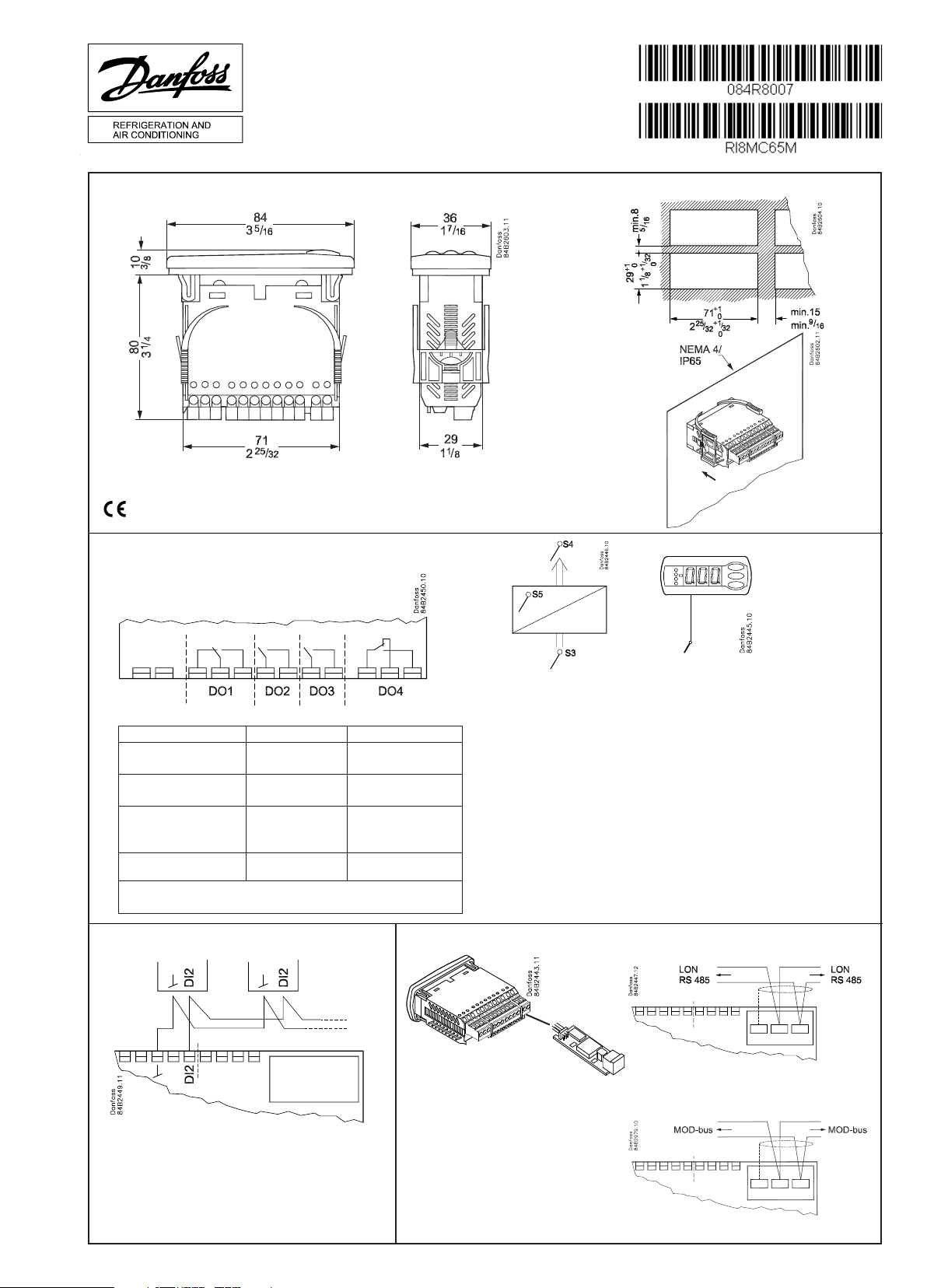
t
= 0 - +55°C, 32 - +131°F
amb
115 V a.c., 50/60 Hz
2.5 VA
10 V < U < 256 V
084R8007
CE (250 V a.c.) UL *** (240 V a.c.)
DO1. Refrigeration * 10 (6) A
DO2. Defrost * 10 (6) A
DO3. Fan or
refrigeration 2 *
DO4. Alarm, light, rail heat
or hotgas defrost *
* DO1 and DO2 are 16 A relays. DO3 and DO4 are 8 A relays. Max. load must be keept.
** Gold plating ensures make function with small contact loads
*** UL-approval based on 30000 couplings
6 (3) A
4 (1) A
Min. 100 mA**
10 A Resistive
5FLA, 30LRA
10 A Resistive
5FLA, 30LRA
6 A Resistive
3FLA, 18LRA
131 VA Pilot duty
4 A Resistive
131 VA Pilot duty
Coordinated defrost
Data communication
Type: Pt 1000 (1000 Ω /0°C ) /
Ptc 1000 (1000 Ω /25°C ) /
NTC-M2020 (5000 Ω / 25°C)
( o06)
LON RS485
MOD-bus
RI8MC65M 08-2011
Page 2
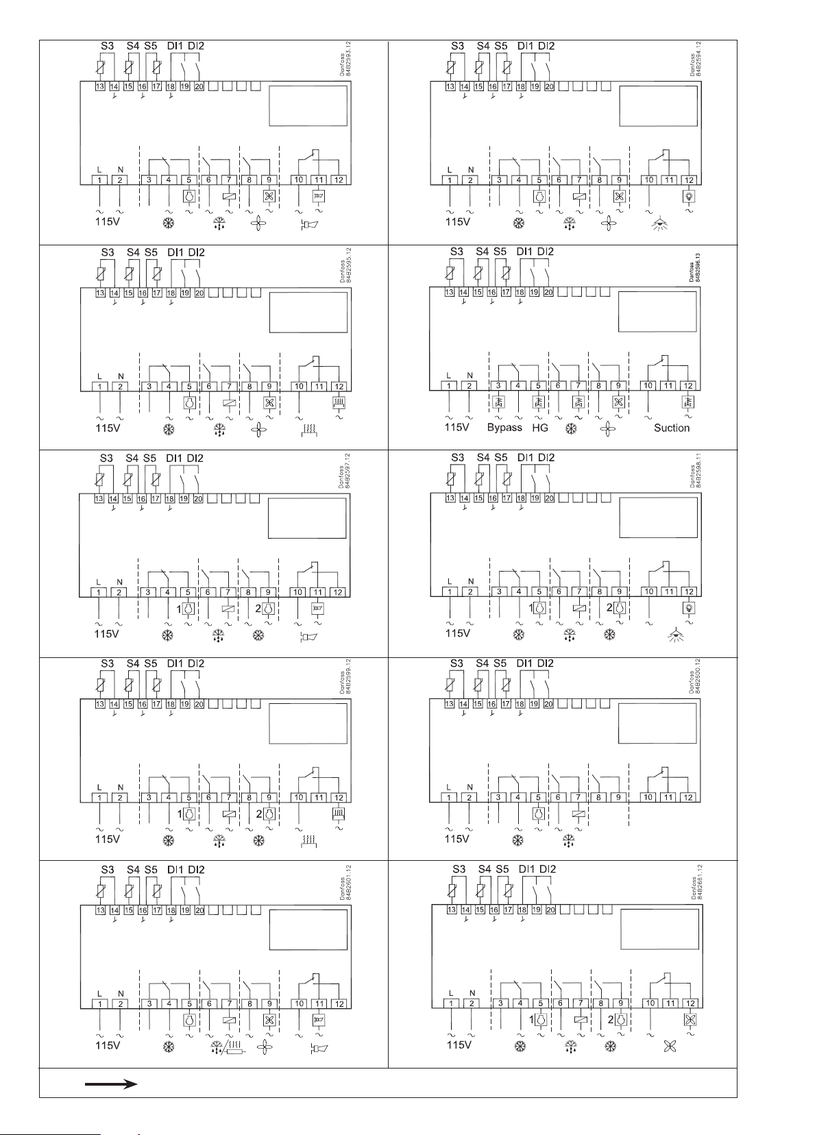
o61 — Electrical connections
1 2
*)
*)
3 4
5 6
*)
*) *)
*)
7 8
9 10
*)
*)*)
*)
! ! !
2 Instructions RI8MC65M © Danfoss 8/2011 AK-CC 210
*) DI1, DI2: AU: Guld, Gold, Or, Oro l = max. 15 m
Page 3
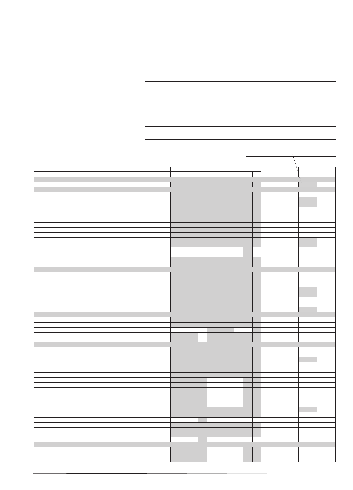
Setting:
1 Open parameter r12 and stop the regulation
2 Select electric connection based on the draw-
ings on page 2
3 Open parameter o61 and set the electric con-
nection number in it
4 Now select one of the preset settings from the
table on the right-hand side
5 Open parameter o62 and set the number for
the array of presettings
6 Open parameter r12 and start the regulation
7 Go through the survey of factory settings.
Make any necessary changes in the respective
parameters.
8 For network. Set the address in o03 and then
transmit it to the gateway/system unit with
setting o04.
English (°C)
Auxiliary table for settings
(quick-setup)
Preset settings (o62) 1 2 3 4 5 6
Temperature (SP)
Max. temp. setting (r02)
Min. temp. setting (r03)
Sensor signal for thermostat. S4% (r15)
Alarm limit high (A13)
Alarm limit low (A14)
Sensor signal for alarm funct.S4% (A36)
Interval between defrost (d03)
Defrost sensor: 0=time, 1=S5, 2=S4 (d10)
DI1 config. (o02)
Sensor signal for display view S4% (017)
Defrost
stop on
time
4°C 2°C -24°C 6°C 3°C -22°C
6°C 4°C -22°C 8°C 5°C -20°C
2°C 0°C -26°C 4°C 1°C -24°C
10°C 8°C -15°C 10°C 8°C -15°C
-5°C -5°C -30°C 0°C 0°C -30°C
6 h 6h 12h 8h 8h 12h
Case Room
Defrost stop
on S5
100% 0%
100% 0%
0 1 1 0 1 1
Case cleaning =10 Door function =3
100% 0%
Array 1-6: The settings in the grey fields will be changed
Defrost
stop on
time
Defrost stop
on S5
Function Codes 1 2 3 4 5 6 7 8 9 10
Normal operation
Temperature (set point) --- -50.0°C 50.0°C 2.0°C
Thermostat
Differential *** r01 0.0 K 20.0K 2.0 K
Max. limitation of setpoint setting *** r02 -49.0°C 50°C 50.0°C
Min. limitation of setpoint setting *** r03 -50.0°C 49.0°C -50.0°C
Adjustment of temperature indication r04 -20.0 K 20.0 K 0.0 K
Temperature unit (°C/°F) r05 °C °F °C
Correction of the signal from S4 r09 -10.0 K +10.0 K 0.0 K
Correction of the signal from S3 r10 -10.0 K +10.0 K 0.0 K
Manual service, stop regulation, start regulation (-1, 0, 1) r12 -1 1 0
Displacement of reference during night operation r13 -10.0 K 10.0 K 0.0 K
Definition and weighting, if applicable, of thermostat sensors
- S4% (100%=S4, 0%=S3)
The heating function is started a number of degrees below the
thermostats cutout temperature
Activation of reference displacement r40 r39 OFF ON OFF
Value of reference displacement (activate via r39 or DI) r40 -50.0 K 50.0 K 0.0 K
Alarm
Delay for temperature alarm A03 0 min 240 min 30 min
Delay for door alarm *** A04 0 min 240 min 60 min
Delay for temperature alarm after defrost A12 0 min 240 min 90 min
High alarm limit *** A13 -50.0°C 50.0°C 8.0°C
Low alarm limit *** A14 -50.0°C 50.0°C -30.0°C
Alarm delay DI1 A27 0 min 240 min 30 min
Alarm delay DI2 A28 0 min 240 min 30 min
Signal for alarm thermostat. S4% (100%=S4, 0%=S3) A36 0% 100% 100%
Compressor
Min. ON-time c01 0 min 30 min 0 min
Min. OFF-time c02 0 min 30 min 0 min
Time delay for cutin of comp.2 c05 0 sec 999 sec 0 sec
Compressor relay 1 must cutin and out inversely
(NC-function)
Defrost
Defrost method (none/EL/GAS/BRINE) d01 no bri EL
Defrost stop temperature d02 0.0°C 25.0°C 6.0°C
Interval between defrost starts d03 0 hours
Max. defrost duration d04 0 min 180 min 45 min
Displacement of time on cutin of defrost at start-up d05 0 min 240 min 0 min
Drip off time d06 0 min 60 min 0 min
Delay for fan start after defrost d07 0 min 60 min 0 min
Fan start temperature d08 -15.0°C 0.0°C -5.0°C
Fan cutin during defrost
0: Stopped
1: Running
2: Running during pump down and defrost
Defrost sensor (0=time, 1=S5, 2=S4) d10 0 2 0
Pump down delay d16 0 min 60 min 0 min
Drain delay d17 0 min 60 min 0 min
Max. aggregate refrigeration time between two defrosts d18 0 hours 48 hours 0 hours
Defrost on demand - S5 temperature’s permitted variation during frost build-up. On central plant choose 20 K (=off)
Delay of hot gas injection d23 0 min 60 min 0 min
Fan
Fan stop at cutout compressor F01 no yes no
Delay of fan stop F02 0 min 30 min 0 min
Fan stop temperature (S5) F04 -50.0°C 50.0°C 50.0°C
Parameters EL-diagram number (page 2)
r15 0% 100% 100%
r36 -15.0 K -3.0 K -15.0 K
c30 0
d09 0 2 1
d19 0.0 K 20.0 k 20.0 K
Min.value
OFF
Max.value
1
ON
240 hours
Factory
setting
0
OFF
8 hours
Actual
setting
AK-CC 210 Instructions RI8MC65M © Danfoss 8/2011 3
Page 4

HACCP
Actual temperature measurement for the HACCP function h01
Last registered peak temperature h10
Selection of function and sensor for the HACCP function. 0 = no
HACCP function. 1 = S4 used (maybe also S3). 2 = S5 used
Alarm limit for the HACCP function h12 -50.0°C 50.0°C 8.0°C
Time delay for the HACCP alarm h13 0 min. 240 min. 30 min.
Select signal for the HACCP function. S4% (100% = S4, 0% = S3) h14 0% 100% 100%
Real time clock
Six start times for defrost.
Setting of hours.
0=OFF
Six start times for defrost.
Setting of minutes.
0=OFF
Clock - Setting of hours *** t07 0 hours 23 hours 0 hours
Clock - Setting of minute *** t08 0 min 59 min 0 min
Clock - Setting of date *** t45 1 31 1
Clock - Setting of month *** t46 1 12 1
Clock - Setting of year *** t47 0 99 0
Miscellaneous
Delay of output signals after start-up o01 0 s 600 s 5 s
Input signal on DI1. Function:
0=not used. 1=status on DI1. 2=door function with alarm when
open. 3=door alarm when open. 4=defrost start (pulse-pressure). 5=ext.main switch. 6=night operation 7=change reference (activate r40). 8=alarm function when closed. 9=alarm
function when open. 10=case cleaning (pulse pressure).
11=forced cooling at hot gas defrost.
Network address (0=off) o03 0 240 0
On/Off switch (Service Pin message)
IMPORTANT! o61 must be set prior to o04
Access code 1 (all settings) o05 0 100 0
Used sensor type (Pt /PTC/NTC) o06 Pt ntc Pt
Display step = 0.5 (normal 0.1 at Pt sensor) o15 no yes no
Max hold time after coordinated defrost o16 0 min 60 min 20
Select signal for display view. S4% (100%=S4, 0%=S3) o17 0% 100% 100%
Input signal on DI2. Function:
(0=not used. 1=status on DI2. 2=door function with alarm when
open. 3=door alarm when open. 4=defrost start (pulse-pressure). 5=ext. main switch 6=night operation 7=change reference (activate r40). 8=alarm function when closed. 9=alarm
function when open. 10=case cleaning (pulse pressure).
11=forced cooling at hot gas defrost.). 12=coordinated defrost)
Configuration of light function (relay 4)
1=ON during day operation. 2=ON / OFF via data communication. 3=ON follows the DI-function, when DI is selected to door
function or to door alarm
Activation of light relay (only if o38=2) o39 OFF ON OFF
Rail heat On time during day operations o41 0% 100% 100
Rail heat On time during night operations o42 0% 100% 100
Rail heat period time (On time + Off time) o43 6 min 60 min 10 min
Case cleaning. 0=no case cleaning. 1=Fans only. 2=All output
Off.
Selection of EL diagram. See overview page 2 * o61 1 10 1
Download a set of predetermined settings. See overview
previous page.
Access code 2 (partly access) *** o64 0 100 0
Save the controllers present settings to the programming key.
Select your own number.
Load a set of settings from the programming key (previously
saved via o65 function)
Replace the controllers factory settings with the present settings
Service
Status codes are shown on page 5 S0-S33
Temperature measured with S5 sensor *** u09
Status on DI1 input. on/1=closed u10
Temperature measured with S3 sensor *** u12
Status on night operation (on or off) 1=closed *** u13
Temperature measured with S4 sensor *** u16
Thermostat temperature u17
Read the present regulation reference u28
Status on DI2 output. on/1=closed u37
Temperature shown on display u56
Measured temperature for alarm thermostat u57
Status on relay for cooling ** u58
Status on relay for fan ** u59
Status on relay for defrost ** u60
Status on relay for railheat ** u61
Status on relay for alarm ** u62
Status on relay for light ** u63
Status on relay for valve in suction line ** u64
Status on relay for compressor 2 ** u67
*** o46 0 2 0
* o62 0 6 0
1 2 3 4 5 6 7 8 9 10
h11 0 2 0
t01-t06 0 hours 23 hours 0 hours
t11-t16 0 min 59 min 0 min
o02 1 11 0
o04 OFF ON OFF
o37 0 12 0
o38 1 3 1
o65 0 25 0
o66 0 25 0
o67 OFF On OFF
*) Can only be set when regulation is stopped (r12=0)
**) Can be controlled manually, but only when r12=-1
***) With access code 2 the access to these menus will be limited
Factory settings are indicated for standard units. Other code numbers have customized settings.
SW = 2.3x
4 Instructions RI8MC65M © Danfoss 8/2011 AK-CC 210
Page 5

The buttons
LED
Set menu
1. Push the upper button until a parameter
r01 is shown
2. Push the upper or the lower button and
find that parameter you want to change
3. Push the middle button until the
parameter value is shown
4. Push the upper or the lower button and
select the new value
5. Push the middle button again to enter
the value.
Cutout alarm relay / receipt alarm/see alarm
code
Set temperature
1. Push the middle button until the
temperature value is shown
2. Push the upper or the lower button and
select the new value
3. Push the middle button to select the
setting.
Reading the temperature at defrost sensor
• Push briey the lower button
Manuel start or stop of a defrost
• Push the lower button for four seconds.
Light emitting diode
= refrigeration
= defrost
= fan running
Flashes fast at alarm
HACCP
HACCP function is active
• Push short the upper button
See HACCP registration
1. Give the middle button a long push until
h01 appears
2. Select required h01-h10
3. See value by giving the middle button a
short push
Fault code display Alarm code display Status code display
E 1 Fault in controller A 1 High temperature alarm S0 Regulating
E 6 Change battery + check clock A 2 Low temperature alarm S 1 Waiting for end of the coordinated defrost
E 25 S3 sensor error A 4 Door alarm S 2 ON-time Compressor
E 26 S4 sensor error A 5 Max. Hold time S 3 OFF-time Compressor
E 27 S5 sensor error A 15 DI 1 alarm S 4 Drip-off time
A 16 DI 2 alarm S 10 Refrigeration stopped by main switch
A 45 Standby mode S 11 Refrigeration stopped by thermostat
A 59 Case cleaning S 14 Defrost sequence. Defrosting
A 60 HACCP alarm S 15 Defrost sequence. Fan delay
S 17 Door open (open DI input)
S 20 Emergency cooling
S 25 Manual control of outputs
S 29 Case cleaning
S 30 Forced cooling
S 32 Delay of output at start-up
S33 Heat function r36 is active
non The defrost temperature cannot be dis-
played. There is stop based on time
-d- Defrost in progress
PS Password required
AK-CC 210 Instructions RI8MC65M © Danfoss 8/2011 5
Page 6

English (° F)
Setting:
1 Open parameter r12 and stop the regulation
2 Select electric connection based on the draw-
ings on page 2
3 Open parameter o61 and set the electric con-
nection number in it
4 Now select one of the preset settings from the
table on the right-hand side
5 Open parameter o62 and set the number for
the array of presettings
6 Open parameter r12 and start the regulation
7 Go through the survey of factory settings.
Make any necessary changes in the respective
parameters.
8 For network. Set the address in o03 and then
Auxiliary table for settings
(quick-setup)
Preset settings (o62) 1 2 3 4 5 6
Temperature (SP)
Max. temp. setting (r02)
Min. temp. setting (r03)
Sensor signal for thermostat. S4% (r15)
Alarm limit high (A13)
Alarm limit low (A14)
Sensor signal for alarm funct.S4% (A36)
Interval between defrost (d03)
Defrost sensor: 0=time, 1=S5, 2=S4 (d10)
DI1 config. (o02)
Sensor signal for display view S4% (017)
Defrost
stop on
time
39°F 36°F -11°F 43°F 37°F -8°F
43°F 39°F -8°F 46°F 41°F -4°F
36°F 32°F -15°F 39°F 34°F -11°F
50°F 46°F 5°F 50°F 46°F 5°F
23°F 23°F -22°F 32°F 32°F -22°F
6 h 6h 12h 8h 8h 12h
transmit it to the gateway/system unit with
setting o04.
Function Codes 1 2 3 4 5 6 7 8 9 10
Normal operation
Temperature (set point) --- -58.0°F 122.0°F 36.0°F
Thermostat
Differential *** r01 0°F 36.0°F 36.0°F
Max. limitation of setpoint setting *** r02 -56.0°F 122°F 122°F
Min. limitation of setpoint setting *** r03 -58.0°F 120°F -58.0°F
Adjustment of temperature indication r04 -4.0°F 68.0°F 32.0°F
Temperature unit (°C/°F) r05 °C °F °F
Correction of the signal from S4 r09 -18.0°F +18.0°F 0.0°F
Correction of the signal from S3 r10 -18.0°F +18.0°F 0.0°F
Manual service, stop regulation, start regulation (-1, 0, 1) r12 -1 1 0
Displacement of reference during night operation r13 -18.0°F +18.0°F 0.0°F
Definition and weighting, if applicable, of thermostat sensors
- S4% (100%=S4, 0%=S3)
The heating function is started a number of degrees below the
thermostats cutout temperature
Activation of reference displacement r40 r39 OFF ON OFF
Value of reference displacement (activate via r39 or DI) r40 -90.0°F 90.0°F 0.0°F
Alarm
Delay for temperature alarm A03 0 min 240 min 30 min
Delay for door alarm *** A04 0 min 240 min 60 min
Delay for temperature alarm after defrost A12 0 min 240 min 90 min
High alarm limit *** A13 -58.0°F 122.0°F 46.0°F
Low alarm limit *** A14 -58.0°F 122.0°F -22.0°F
Alarm delay DI1 A27 0 min 240 min 30 min
Alarm delay DI2 A28 0 min 240 min 30 min
Signal for alarm thermostat. S4% (100%=S4, 0%=S3) A36 0% 100% 100%
Compressor
Min. ON-time c01 0 min 30 min 0 min
Min. OFF-time c02 0 min 30 min 0 min
Time delay for cutin of comp.2 c05 0 sec 999 sec 0 sec
Compressor relay 1 must cutin and out inversely
(NC-function)
Defrost
Defrost method (none/EL/GAS/BRINE) d01 no bri EL
Defrost stop temperature d02 32.0°F 77.0°F 43.0°F
Interval between defrost starts d03 0 hours
Max. defrost duration d04 0 min 180 min 45 min
Displacement of time on cutin of defrost at start-up d05 0 min 240 min 0 min
Drip off time d06 0 min 60 min 0 min
Delay for fan start after defrost d07 0 min 60 min 0 min
Fan start temperature d08 5.0°F 32.0°F 23.0°F
Fan cutin during defrost
0: Stopped
1: Running
2: Running during pump down and defrost
Defrost sensor (0=time, 1=S5, 2=S4) d10 0 2 0
Pump down delay d16 0 min 60 min 0 min
Drain delay d17 0 min 60 min 0 min
Max. aggregate refrigeration time between two defrosts d18 0 hours 48 hours 0 hours
Defrost on demand - S5 temperature’s permitted variation during frost build-up. On central plant choose 20 K (=off)
Delay of hot gas injection d23 0 min 60 min 0 min
Fan
Fan stop at cutout compressor F01 no yes no
Delay of fan stop F02 0 min 30 min 0 min
Fan stop temperature (S5) F04 -58.0°F 122.0°F 122.0°F
Parameters EL-diagram number (page 2)
r15 0% 100% 100%
r36 -27.0°F -5.0°F -22.0°F
c30 0
d09 0 2 1
d19 0°F 36.0°F 36.0° F
Case Room
Defrost stop
on S5
100% 0%
100% 0%
0 1 1 0 1 1
Case cleaning =10 Door function =3
100% 0%
Array 1-6: The settings in the grey fields will be changed
Min.value
OFF
Defrost
stop on
time
Max.value
1
ON
240 hours
Defrost stop
Factory
setting
0
OFF
8 hours
on S5
Actual
setting
6 Instructions RI8MC65M © Danfoss 8/2011 AK-CC 210
Page 7

HACCP
Actual temperature measurement for the HACCP function h01
Last registered peak temperature h10
Selection of function and sensor for the HACCP function. 0 = no
HACCP function. 1 = S4 used (maybe also S3). 2 = S5 used
Alarm limit for the HACCP function h12 -58.0°F 122.0°F 46.0°F
Time delay for the HACCP alarm h13 0 min. 240 min. 30 min.
Select signal for the HACCP function. S4% (100% = S4, 0% = S3) h14 0% 100% 100%
Real time clock
Six start times for defrost.
Setting of hours.
0=OFF
Six start times for defrost.
Setting of minutes.
0=OFF
Clock - Setting of hours *** t07 0 hours 23 hours 0 hours
Clock - Setting of minute *** t08 0 min 59 min 0 min
Clock - Setting of date *** t45 1 31 1
Clock - Setting of month *** t46 1 12 1
Clock - Setting of year *** t47 0 99 0
Miscellaneous
Delay of output signals after start-up o01 0 s 600 s 5 s
Input signal on DI1. Function:
0=not used. 1=status on DI1. 2=door function with alarm when
open. 3=door alarm when open. 4=defrost start (pulse-pressure). 5=ext.main switch. 6=night operation 7=change reference (activate r40). 8=alarm function when closed. 9=alarm
function when open. 10=case cleaning (pulse pressure).
11=forced cooling at hot gas defrost.
Network address (0=off) o03 0 240 0
On/Off switch (Service Pin message)
IMPORTANT! o61 must be set prior to o04
Access code 1 (all settings) o05 0 100 0
Used sensor type (Pt /PTC/NTC) o06 Pt ntc Pt
Display step = 0.5 (normal 0.1 at Pt sensor) o15 no yes no
Max hold time after coordinated defrost o16 0 min 60 min 20
Select signal for display view. S4% (100%=S4, 0%=S3) o17 0% 100% 100%
Input signal on DI2. Function:
(0=not used. 1=status on DI2. 2=door function with alarm when
open. 3=door alarm when open. 4=defrost start (pulse-pressure). 5=ext. main switch 6=night operation 7=change reference (activate r40). 8=alarm function when closed. 9=alarm
function when open. 10=case cleaning (pulse pressure).
11=forced cooling at hot gas defrost.). 12=coordinated defrost)
Configuration of light function (relay 4)
1=ON during night operation. 2=ON / OFF via data communication. 3=ON follows the DI-function, when DI is selected to door
function or to door alarm
Activation of light relay (only if o38=2) o39 OFF ON OFF
Rail heat On time during day operations o41 0% 100% 100
Rail heat On time during night operations o42 0% 100% 100
Rail heat period time (On time + Off time) o43 6 min 60 min 10 min
Case cleaning. 0=no case cleaning. 1=Fans only. 2=All output
Off.
Selection of EL diagram. See overview page 2 * o61 1 10 1
Download a set of predetermined settings. See overview
previous page.
Access code 2 (partly access) *** o64 0 100 0
Save the controllers present settings to the programming key.
Select your own number.
Load a set of settings from the programming key (previously
saved via o65 function)
Replace the controllers factory settings with the present settings
Service
Status codes are shown on page 8 S0-S33
Temperature measured with S5 sensor *** u09
Status on DI1 input. on/1=closed u10
Temperature measured with S3 sensor *** u12
Status on night operation (on or off) 1=closed *** u13
Temperature measured with S4 sensor *** u16
Thermostat temperature u17
Read the present regulation reference u28
Status on DI2 output. on/1=closed u37
Temperature shown on display u56
Measured temperature for alarm thermostat u57
Status on relay for cooling ** u58
Status on relay for fan ** u59
Status on relay for defrost ** u60
Status on relay for railheat ** u61
Status on relay for alarm ** u62
Status on relay for light ** u63
Status on relay for valve in suction line ** u64
Status on relay for compressor 2 ** u67
*) Can only be set when regulation is stopped (r12=0)
**) Can be controlled manually, but only when r12=-1
***) With access code 2 the access to these menus will be limited
Factory settings are indicated for standard units. Other code numbers have customized settings.
*** o46 0 2 0
* o62 0 6 0
1 2 3 4 5 6 7 8 9 10
h11 0 2 0
t01-t06 0 hours 23 hours 0 hours
t11-t16 0 min 59 min 0 min
o02 1 11 0
o04 OFF ON OFF
o37 0 12 0
o38 1 3 1
o65 0 25 0
o66 0 25 0
o67 OFF On OFF
SW = 2.3x
AK-CC 210 Instructions RI8MC65M © Danfoss 8/2011 7
Page 8

The buttons
LED
Set menu
1. Push the upper button until a parameter
r01 is shown
2. Push the upper or the lower button and
find that parameter you want to change
3. Push the middle button until the
parameter value is shown
4. Push the upper or the lower button and
select the new value
5. Push the middle button again to enter
the value.
Cutout alarm relay / receipt alarm/see alarm
code
Set temperature
1. Push the middle button until the
temperature value is shown
2. Push the upper or the lower button and
select the new value
3. Push the middle button to select the
setting.
Reading the temperature at defrost sensor
• Push briey the lower button
Manuel start or stop of a defrost
• Push the lower button for four seconds.
Light emitting diode
= refrigeration
= defrost
= fan running
Flashes fast at alarm
HACCP
HACCP function is active
• Push short the upper button
See HACCP registration
1. Give the middle button a long push until
h01 appears
2. Select required h01-h10
3. See value by giving the middle button a
short push
Fault code display Alarm code display Status code display
E 1 Fault in controller A 1 High temperature alarm S0 Regulating
E 6 Change battery + check clock A 2 Low temperature alarm S 1 Waiting for end of the coordinated defrost
E 25 S3 sensor error A 4 Door alarm S 2 ON-time Compressor
E 26 S4 sensor error A 5 Max. Hold time S 3 OFF-time Compressor
E 27 S5 sensor error A 15 DI 1 alarm S 4 Drip-off time
A 16 DI 2 alarm S 10 Refrigeration stopped by main switch
A 45 Standby mode S 11 Refrigeration stopped by thermostat
A 59 Case cleaning S 14 Defrost sequence. Defrosting
A 60 HACCP alarm S 15 Defrost sequence. Fan delay
S 17 Door open (open DI input)
S 20 Emergency cooling
S 25 Manual control of outputs
S 29 Case cleaning
S 30 Forced cooling
S 32 Delay of output at start-up
S33 Heat function r36 is active
non The defrost temperature cannot be dis-
played. There is stop based on time
-d- Defrost in progress
PS Password required
8 Instructions RI8MC65M © Danfoss 8/2011 AK-CC 210
 Loading...