

Page 1
lnstallation
& User
Guide
Z-Wave
RS
Room
Sensor
&t#
+ä{
Edk
Page 2
hffillE-
i!.rhG
lnstallation &
User
Guide Z-Wave
RS
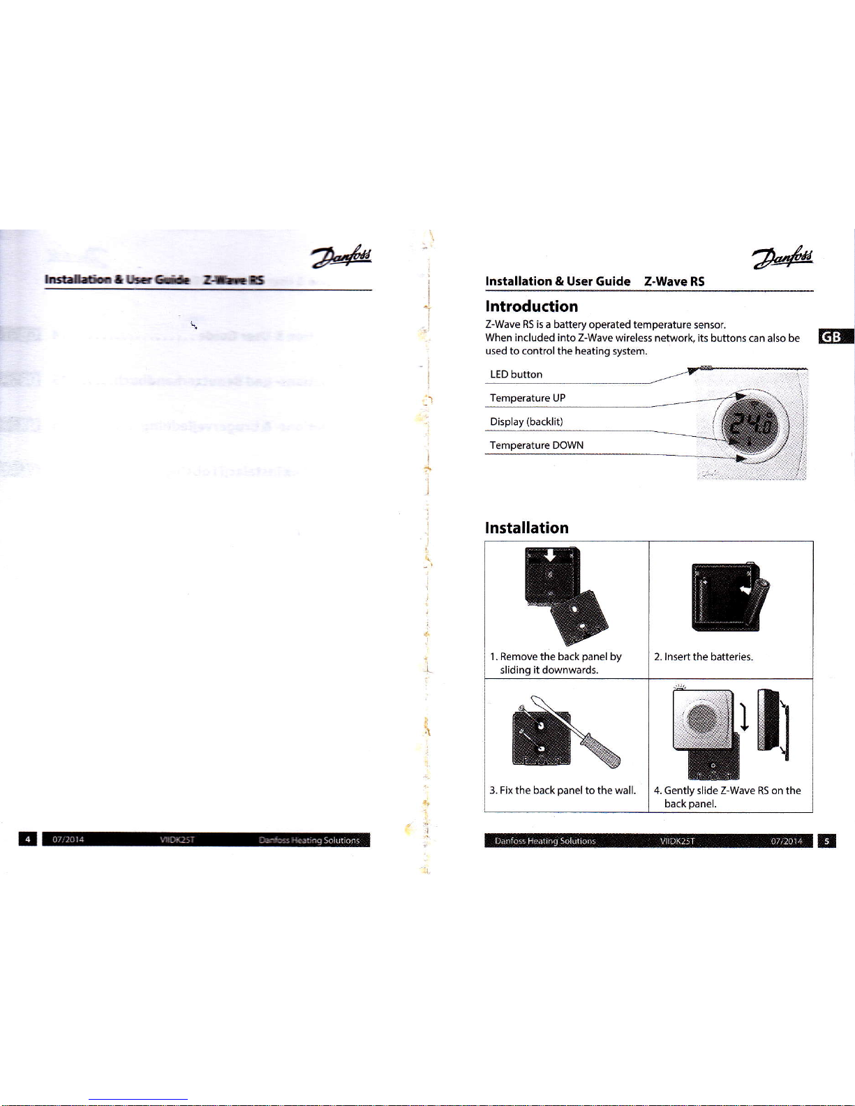
lntroduction
Z-Wave
RS is
a battery operated temperature
sensor.
When included
into Z-Wave wireless network, its
buttons can also be
u5ed to control the heating system.
LED
button
Eril
Temperature UP
(backlit)
Temperature DOWN
lnstallation
1. Remove
the
back
panel
by
slidinq
it
downward5.
2. lnsert the batteries.
3.
Fix
the back
panel
to the wall 4. Gently slide Z-Wave
RS
on the
back
panel.
Page 3

Displaylrfrr*
lnstalletictffi
nH
lEtallation & User Guide Z-Wave RS
ET.I
Erb
-lrE:-ltrRS
6rdü,hrk
d
!t
rry
i!ßfÜ'*@lü:Crü!ds
E
HH:P
Z-wave info
Gensic Deute Class
Muttilaelffi
SEanF( feri=
C6 Eqirrq Lirdtied
sss
Deidqr
noÄtng
slaE
fdcskrc
Z-wave
command classes
8A5tC
Basic
5ET: Not Supported
Basic GET: Multilevel Sensor Get
Basic REPORT: Multilevel Sensor
Report
(1'C
accuracy)
MANUFACTURER_
SPECtFtC
v2 Danfoss and Z-Wave RS lDs
VERSION
v2
Version ofthe command classes, the
Z-wave library and the Z-Wave Rs
BATTERY Battery status
MULTI-CMD
Conserve battery, transmitting mul-
tiple commands in
a single
packet
WAKE UP v2
Wake-up interual range 5 min. to
24h
(default:
60 minutes)
PROTECTION v2
0
=
No
protection
2
=
User interface locked
CONFIGURATION v2
Z-Wave RS specific confiquration.
SENSOR_
MULTILEVEL
V6
Reports reading from the room
temperature sensor.
CENTRAL_SCENE
Pushing the LED button triggers
transmission of CENTRAL_SCENE_
NOTIFICATION.
THERMOSTAT
SETPOINT
V3
When
a set-pointtemperature
is
selected on the display, a set-point
report containing the value is sent
to the controller.
SCHEDULE
When
a temperature and
number
ofhours are selected on the display,
an override schedule report will be
5ent to the controller containing
the
value5.
INDICATOR
Control ofthe LED indication
tad
lrE
rld
G
EdHtG,
30ffid
Crilid
bdterylsl
ß
Tamper-proof
enabled bythe controller
Page 4

lnstallation
& UserGdde
Z{eßs
T
I
i
I
Hlation
& User Guide
Z-Wave RS
GTJI
OxoO
/
0x0l
/
oo2
When the LED
button is clicked
a CENTRAL_SCENE
NOTIFICA-
TION is
sentto the.ontroller-
Functions
SENSOR_
|
The rom
tmpenture
can
MULTILEVEL
I
bereadmthedisptay,as
lfu
indicted
bythe i@l when
included
into Z-Wave
network,
a temperature
report is
sentto
the
controller
during wake-up
and also
when the temperature
has
changed beyond
configured
threshold limit.
Cmmand CIass THERMOSTAI
SETPOINT
The up and down arrow
buttons
are used to select a new
set-
point
temperature.
After a set-point
has been 5e-
leded,
itwill flash for 5 seconds.
Afterthat the
measured
temperature is displayed
again
and
the Z-Wave RS sends
the
selected temperature
as a THER-
MOSTAT_SErPOlNT_REPORT
to
the Z-Wave controller.
rIiNFtGußÄT{§N1:o[rMn üft:16§: ür&ult,
naasä
Setpoint control
function
Enabled Disabled / enabled
Set-point
display resolution
o-5"c
From 0.1
to I 0'C
in 0.1"C steps
Max set-point
and ovetride
limit 28"C
From min setpoinV
override limit to
max
40'C
Min set-point
and override
limit r 2"c
From min 0'C
to
max. setpoint/
override limit
;
Setpoint
Type in Thermostat-
:
Setpoint
Reports
Heating #1
Heating #1,
Cooling
#t,
Auto Chanqeover
IND€ATOR
. The
cmtrolls cn start
and
OoEF
=
St"^ tED
'top_a
ffölting iMi@tion
of the
flash 6rkh
.
LED hntm
6irE tlE
lndiGtor
Set command- The
teqmcy,
0xO0=Stop
i
numbscfllastEdrdcolorof
running
session
i
tie sjm
re @to{ed
by 4
i
cmfgwtim prrnAer:
lndicator s€t
LEDontime
lmc
lmbsoocinloo
6s5
LED Flash
period
I 5
C!D65535
ffids
NumberoflEDflashs(dmtirl
5 Ob255ßa.*E
LEDColour
frE
c@f,Ed
Page 5

lnstallati.rn
& lrs€r
G-d.
Z-hIS
lfl
Cqryudrt<
isOCI'Ii
Max
*t-pdntildryileH
Min set-point
and
@ire
hi
tzr[
I rlErp-ddoirralw
brfüons
c Ged to
sd<t
tfE temporary
ryiretsnprature.
'
The
s&d
Elw fl6hes
on
r lfie
ddaüfo.5
§onds.
i
Be6re
tlE
5
gmds
are
gone,
I
pudr
the LID
button
to select
:
Dumber
ofhouE
to
overide.
i
The
slected
number
of
hours
;
will
fash for
5
seconds.
After
I
that the
measured
temperature
i
is
displayed
aqain
and
the
i Z-Wave
RS sends
the
selected
'
tmpeEtu.eand
the
numberof
hqrE
6 a
SCHEDU|E_REPORT
to
tfE Z-Waw
cmroller
km
trit
reqE nV
Gtile tritto
|E{nC
kemOtto
.Er4,.irt/Gr
ihH
töeülü
En#
C»sbted
/ Embled
Saa<*tdspbynd.in
tl5t
kmol
to'loPc
in
Configuration
Command
Class
iL
lofrnä,idtlitria:r
aär:aiidßEl'"irr::
.:üd,äst:
RadtF'..:.'.+
+..*..-Sf!i},l.
[emperature
Report
lhreshold
0.5"c
1 to 10'C
2 bytes
1
=
0.1'C
1 00
=
10.0'C
2
set-point
display
resolution
0.5"c
From 0.1
to
lo'C in 0.1'C
stePs
2 bytes
I
=0.1'C
100= 10-0"(
3
vlin set-pointand
)verride limit
'12'(
From
min
0'C to
max
setpoinvover
ride limit
2 bytes
0=0"C
40
=40'C
Max seFpoint
and
overiide
limit
28'C
From
min
setpoint/ovetr
ride limitto
max
40'c
6
Setpoint control
function
Enabled
Disabled /
enabled
I byte
C
=
Disabled
1
=
Enabled
7
Temporarily
overide
scheduier
Enabled Disabled /
enabled
8 SetpointType
in
Thermostat_
Setpoint
Repods
Heätin9
leatin9
#1,
:ooling #1,
\uto
lhanoeover
I byte
1
=
Heating
#l
2
=
Cooling
#'l
10
=
Auto Chanqeover
9
LED on time
100ms 100 to 500ms
in
100ms
step5
I byte
1
=
100ms
5
=
500ms
5
ED Flash
period 0to
65535
seaonds
2 bytes
t0
'tumberofLED
lashes
(duration)
5
0 to
255
flashes
I byte
11
ED Color
Green. Red I byte
lxol
=
Green
lx02
=
Red
lnstallation & User Guide
Z-Wave
RS
q
Page 6

lnstaLri.rlltG*
t*l§
Z-lYavef,ehrls
T}EZ-WbrrßS@ihifüdidLdiTdhr!
Z:kt€ rEtrcrk
with .ffis Z*brc
@fu
oh*:üom
rnry da Mtfuuc
All
cqrg|üy
poEEdz-ktrffi
müE-rcEffi r.il
*tas
repeats
Egad6 ditE
EmXü
Z-lYave best
pedic
.
Aftsa
qr@5§fr.a
t!d6irc'
üiE
@ü@klrctsd.W XE_UP_
lNTERar' L_sEI@nd
brüEzslcß n artuD
sFtiry
where
and wtH the
Z+tk i5
dEü mn- *eHy-
.
After
-nding
tt€ WAIE_tP_lüTtUitc._5Ef
@müd. ttE otroller
must
askJn
retun
rü.Ga
I üE Z-bE
qsc
Eiah G dEriEtion
i.e. the ndD
rd
irrtE
l{füE_1JP-HImilnL_5Fwd
.
The nodelD
*t
in
the WlIE_tP_r{TER[td.-*-f
@rEü
rur be
fora
perumttyEstairg&ar$-h
GprüEthe
mnds
sent trom th€ Z-Wü RS- füEq*irü[d
<ifheerded
periodt
the Z-Wre
flS ra
etlEtrü E@A6L
.
Although
thez-WreRsq+fqts*gbqmds
mslti(uF
mands
must alm)E be
led to
gEre
bB
&t friE
Z-Wave lnclusion
.
Ensure thatthe Z-WareR5irfadryreset
.
Activate
"lnclusion-
s ftE Z+Yüc düob-
.
Press the LED butts
fi tlEZ+tbrEn§
.
Obserye both controlls
ard Z{Vaß RS
fu sfzÖE driE
p.6
Z-Wave Exclusion
'
Activate 'Exclusion'
on the
Z-\ryrc @fiofs,
.
Hold down the 3 buttons
@ tlE Z-Wrc nS So.
5 recds
1{p,
dodn
and LED buftons).
.
Obserue both
controller and Z-Ware RS
fu. ffi6 of üE
p.@
lnstallation
& User Guide
Z-Wave RS
Z-Wave
WakeUp
A controller can only communicate
withthe
Z-Wave RS when it
i§
awake.
The interuals
when the Z-Wave RS is awake can
be set using the
WakeUp
Command Class. By
default the Wakeup interval
is 60 minutes
The z-Wave
Rs can be woken manually
by
pushing
any ofthe
three
buttons, and
will stay awake for
10
seconds.
Z-Wave Node
lnformation
Frame
Each time the
LED button is
pressed
the Z-Wave RS
will
and
send NlF.
This is also true
when the Z-Wave RS
i5 in tamper-proofmode.
Factory
Reset
I . Remove
one of the
I
2. Press and hold the
LED button
while
batteries.
J
reinserting the battery
until the
LED
flashes red
(approx.5
seconds).
The Z-
Wave RS
is now reset to
factory defaults,
Eril
Page 7

lnstallation & User Guide Z-wave R5
Technical Specifi <ations
Battery
Alkaline 2 x AA, 1.5 V
Battery lifetime Up to+5
years
Backlight
Green LED
Ambient temperature 0'to
+40"C
Battery monitoring
The
sensor
hasa built-in monitorinq circuit
which will detect
low orcritical battery
level.
Transmission
f
A5a-42 MHz
Transmission range in
normal buildings
upto 30 m
Transmi55ion
power
MaL 1 mW
lP class
21
Dimensions
8I
mmx66mmx2'l mm
Certifications
C(
(rE
o",
 Loading...