

Page 1
Data Sheet
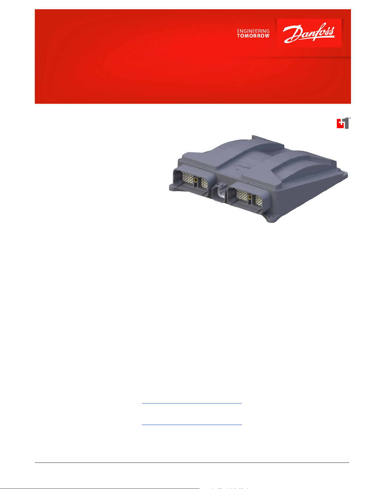
PLUS+1® Controller
XL104-0000
Flexible Machine Management
The XL controller platform provides a solid and
powerful background to meet requirements for
managing mobile machinery. The modular concept of
the XL controller gives you the flexibility meeting a
big range of different needs with the same product.
The high pin count makes it possible to let this
solution fit to control even your most complex
machines.
Product Highlights
The XL controller is a power house employing a 32bit
Processor, providing the controller with very fast
single cycle processing speed and 2.5 MB of internal
flash. The architecture of the XL controller platform
furthermore gives you the opportunity to comply
with current functional safety standards.
Application Development
Users develop XL Controller applications with PLUS
+1® GUIDE. This Microsoft Windows based
development environment features a user-friendly,
field proven, icon-based graphical programming tool,
application downloader, and service/diagnostic tool.
Features
•
User-programmed with PLUS+1® GUIDE
and C Open
•
4 pin DEUTSCH DTP connector for
power and ground
•
2 x 50 pin DEUTSCH DRC connectors
•
Processor: AURIX 32 bit running at 200
MHz 2.5 MB flash, 240kB RAM, Lock Step
Core
•
External memory:
32 kB EEPROM non-volatile memory
‒
64 MB Flash vault memory
‒
•
12 bit analog-to-digital converter
•
7 to 36 Vdc power supply, monitored
internally
•
Sensor power outputs:
‒
‒
•
3 CAN 2.0B ports
•
SIL2 compliant
Comprehensive technical literature is
online at www.danfoss.com
1x 5V Fixed
1x 3V to 12V variable
©
Danfoss | March 2020 AI336661857442en-000101 | 1
Page 2
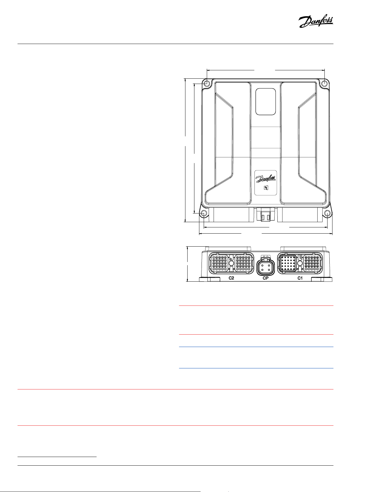
180.00 [7.08]
198.18
[7.80]
219.42
[8.64]
189.06 [7.44]
203.77 [8.02]
53.50 [2.11]
C
C
Data Sheet
XL104-0000 Controller
48 Inputs
•
20 digital (DIN) configurable with pull
up (5 V) or pull down (0 V)
•
4 universal (DIN/AIN/FreqIn) that are
user-defined as either:
Analog: with configurable ranges of
‒
0 to 5.25 V, 0 to 36 V, or 0 to 365 mV;
Digital: pull up (5 V), pull down (0 V),
‒
or pull to center (2.5 V);
Frequency: (timing) 1 Hz to 10 kHz
‒
•
4 universal (DIN/AIN/FreqIn/Rheo/
4-20mA) that are user-defined as either:
Analog: with configurable ranges 0
‒
to 5.25 V, 0 to 36 V, or 0 to 365 mV;
Digital: pull up (5 V), pull down (0 V),
‒
or pull to center (2.5 V);
Frequency: (timing) 1 Hz to 10 kHz
‒
Rheostat: (Resistance) 6 ohms to 10K
‒
ohms
Current: 0.1 mA to 28 mA
‒
•
17 digital/analog (DIN/AIN) that are
user-defined as either:
Digital: pull up (5 V), pull down (0 V),
‒
or pull to center (2.5 V);
Analog: 0 to 5.25 V or 0 to 36 V
‒
•
3 fixed range analog (AIN/CAN shield) 0
to 5.25 V
Dimensions in mm [in]
40 Outputs
•
14 digital (DOUT) 3 A (source only)
•
6 digital (DOUT) 4 A (source only)
•
20 universal (PWMOUT/DOUT/PVGOUT)
that are user-defined as either:
Digital: (3 A), configurable as source
‒
or sink;
PWM: (33 to 4000 Hz*)
‒
Analog voltage: open loop PWM to
‒
4000 Hz
Caution
PCB damage may occur.
To prevent damage to the module all module power supply + pins must be connected to the vehicle power supply to support
advertised module maximum output current capacity. DO NOT use module power supply + pins to supply power to other modules on a
machine.
Caution
Warranty will be voided if device is opened.
Device is not field serviceable. Do not open
the device.
Use care when wiring mating connector.
Pinouts are for device pins.
*
33 to 20kHz in open loop for selected outputs
2 | © Danfoss | March 2020 AI336661857442en-000101
Page 3

CP
1
2
3
4
5
6
45
46
C1
5
6
45
46
C2
Data Sheet
XL104-0000 Controller
1 DEUTSCH DTP 4 pin connector
C2 and C1 - DEUTSCH DRC 50 pin connector
Connector pins (C2)
Pin Function Pin Function
C2-P1 DIN/AIN C2-P26 DIN
C2-P2 DIN/AIN C2-P27 DIN
C2-P3 DIN/AIN C2-P28 DIN
C2-P4 DIN/AIN C2-P29 DIN
C2-P5 DIN/AIN C2-P30 DIN
C2-P6 DIN/AIN C2-P31 PWM/DOUT/PVGOUT
C2-P7 DIN/AIN C2-P32 PWM/DOUT/PVGOUT*
C2-P8 DIN/AIN C2-P33 DOUT
C2-P9 Sensor power (3-12V) C2-P34 DOUT
C2-P10 Sensor ground C2-P35 DOUT (4A)
C2-P11 DIN C2-P36 DOUT (4A)
C2-P12 DIN C2-P37 DOUT
C2-P13 DIN C2-P38 DOUT
C2-P14 DIN C2-P39 PWM/DOUT/PVGOUT
C2-P15 DIN C2-P40 PWM/DOUT/PVGOUT
C2-P16 DIN C2-P41 PWM/DOUT/PVGOUT*
C2-P17 DIN C2-P42 PWM/DOUT/PVGOUT*
C2-P18 DIN C2-P43 DOUT
C2-P19 DIN C2-P44 DOUT
C2-P20 DIN C2-P45 DOUT (4A)
C2-P21 DIN C2-P46 DOUT (4A)
C2-P22 DIN C2-P47 DOUT
C2-P23 DIN C2-P48 DOUT
C2-P24 DIN C2-P49 PWM/DOUT/PVGOUT
C2-P25 DIN C2-P50 PWM/DOUT/PVGOUT
*
PWM: 33 to 20kHz open loop
Connector pins (CP)
Pin Function
C-P1 Power ground C-P2 Power supply +
C-P3 Power supply +
C-P4 Power supply +
Connector pins (C1)
Pin Controller function Pin Controller function
C1-P1 CPU ground - C1-P26 DIN/AIN
C1-P2 CPU supply + C1-P27 DIN/AIN
C1-P3 CAN 0+ C1-P28 DIN/AIN
C1-P4 CAN 0- C1-P29 DIN/AIN
C1-P5 CAN 0 shield/AIN C1-P30 DIN/AIN
*
C1-P6 DIN/AIN C1-P31 PWM/DOUT/PVGOUT
C1-P7 DIN/AIN C1-P32 PWM/DOUT/PVGOUT
C1-P8 Sensor power (5V) C1-P33 DOUT
C1-P9 Sensor ground C1-P34 DOUT
C1-P10 DIN/AIN/Freq C1-P35 DOUT
C1-P11 DIN/AIN C1-P36 DOUT (4A)
C1-P12 DIN/AIN C1-P37 PWM/DOUT/PVGOUT
C1-P13 CAN 1+ C1-P38 PWM/DOUT/PVGOUT*
C1-P14 CAN 1- C1-P39 PWM/DOUT/PVGOUT
C1-P15 CAN 1 shield/AIN C1-P40 PWM/DOUT/PVGOUT
C1-P16 DIN/AIN/FreqIn/Rheo/4-20mA C1-P41 PWM/DOUT/PVGOUT*
C1-P17 DIN/AIN/FreqIn/Rheo/4-20mA C1-P42 PWM/DOUT/PVGOUT*
C1-P18 DIN/AIN/FreqIn/Rheo/4-20mA C1-P43 DOUT
C1-P19 DIN/AIN/FreqIn/Rheo/4-20mA C1-P44 DOUT
C1-P20 DIN/AIN/FreqIn C1-P45 DOUT
C1-P21 DIN/AIN/FreqIn C1-P46 DOUT (4A)
C1-P22 DIN/AIN/FreqIn C1-P47 PWM/DOUT/PVGOUT*
C1-P23 CAN 2+ C1-P48 PWM/DOUT/PVGOUT*
C1-P24 CAN 2- C1-P49 PWM/DOUT/PVGOUT
C1-P25 CAN 2 shield/AIN C1-P50 PWM/DOUT/PVGOUT
*
PWM: 33 to 20kHz open loop
*
©
Danfoss | March 2020 AI336661857442en-000101 | 3
Page 4

Product parameters
Supply voltage 7 to 36 V
Operating temperature (ambient) – 40°C to 85°C [– 40°F to 185°F]
Storage temperature – 55°C to 85°C [– 67°F to 185°F]
IP rating (with mating connector attached) IP 67
EMI/RFI rating 100 V/M
Weight 0.675 kg [1.48 lb]
Vibration IEC 60068-2-64
Shock IEC 60068-2-27
Maximum current, sourcing 40/20A at 70/85°C [158/185°F]
Maximum current, sinking 20/12A at 70/85°C [158/185°F]
Product part number
Order code Part number Description
XL104-0000 11244762 104-pin full populated 48/40 IN/OUT
Part
Description
number
11188220 4 pin DEUTSCH® DTP06-4S mating connector bag
assembly (10 to 14 AWG)
10102024
11249153
50 pin DEUTSCH® DRC26-50S01 (C1) mating connector
bag assembly (16 to 20 AWG)
50 pin DEUTSCH® DRC26-50S02 (C2) mating connector
bag assembly (16 to 20 AWG)
11179523 PLUS+1® GUIDE Professional
Danfoss can accept no responsibility for possible errors in catalogues, brochures and other printed material. Danfoss reserves the right to alter its products without notice. This also applies to products
already on order provided that such alterations can be made without subsequent changes being necessary in specifications already agreed.
All trademarks in this material are property of the respective companies. Danfoss and the Danfoss logotype are trademarks of Danfoss A/S. All rights reserved.
4 | © Danfoss | March 2020 AI336661857442en-000101
 Loading...