

INSTRUCTIONS
INSTRUCTIONS
EC FAN SPEED CONTROLLER
EC FAN SPEED CONTROLLER
Type
Type
IMPORTANT
IMPORTANT
Failure to read and follow all instructions carefully before installing or operating this Fan Speed
Failure to read and follow all instructions carefully before installing or operating this Fan Speed
Controller could cause personal injury and/or property damage. Save these instructions for future use.
Controller could cause personal injury and/or property damage. Save these instructions for future use.
NOTES FOR SAFETY
NOTES FOR SAFETY
!
!
WARNING
WARNING
Before wiring and service, be sure to turn off power supply. Otherwise, may cause electrical shock.
Before wiring and service, be sure to turn off power supply. Otherwise, may cause electrical shock.
Before F.V.S. adjusting, connection of a plug and disassembly of a plug, be sure to turn off power
Before F.V.S. adjusting, connection of a plug and disassembly of a plug, be sure to turn off power
supply as it may cause electrical shock.
supply as it may cause electrical shock.
Do not touch the main body during driving. Otherwise, it may burn a hands.
Do not touch the main body during driving. Otherwise, it may burn a hands.
OUTLINE
OUTLINE
The XGE-*SE fan speed controllers are designed for speed control of electronically commutated (EC) fan motors.
The XGE-*SE fan speed controllers are designed for speed control of electronically commutated (EC) fan motors.
The XGE controls Fan Motor Speed of air cooled condenser of general purpose cold/cooling unit, and keeps a definite condensing
The XGE controls Fan Motor Speed of air cooled condenser of general purpose cold/cooling unit, and keeps a definite condensing
pressure and makes it to drive stably.
pressure and makes it to drive stably.
MOUNTING
MOUNTING
Directly mount onto the pressure line (see Fig.1a) in a location where pressure can be detected accurately (e, g. After the
Directly mount onto the pressure line (see Fig.1a) in a location where pressure can be detected accurately (e, g. After the
condenser) Alternatively it is possible to remote mount to a side panel using the optional fixing bracket (see Fig.8) and
condenser) Alternatively it is possible to remote mount to a side panel using the optional fixing bracket (see Fig.8) and
connect to the pressure line with a refrigeration pipe (not supplied).
connect to the pressure line with a refrigeration pipe (not supplied).
!
!
CAUTION
CAUTION
Don’t install at the place to require degrees of protection over IP65 Category 2 enclosures.
Don’t install at the place to require degrees of protection over IP65 Category 2 enclosures.
Don’t tighten with excessive force whilst holding the unit, since this can result in deformation of the controller.
Don’t tighten with excessive force whilst holding the unit, since this can result in deformation of the controller.
For direct mounting, tighten the connection using an appropriately sized spanner and a torque of 12.7-15Nm (see Fig.2).
For direct mounting, tighten the connection using an appropriately sized spanner and a torque of 12.7-15Nm (see Fig.2).
The mounting position should be in the vertical axis and should not be fitted more than 45°from the vertical (see Fig.1b).
The mounting position should be in the vertical axis and should not be fitted more than 45°from the vertical (see Fig.1b).
Failure to install the Copper Packing at the connection portion cause leak of refrigerant gas.
Failure to install the Copper Packing at the connection portion cause leak of refrigerant gas.
Provide adequate ventilation space so that heat doesn’t build up. At least 50mm clearance above the top and below the bottom
Provide adequate ventilation space so that heat doesn’t build up. At least 50mm clearance above the top and below the bottom
of XGE is necessary. Don’t mount this instrument directly above equipment that generates large amount of heat. (heaters,
of XGE is necessary. Don’t mount this instrument directly above equipment that generates large amount of heat. (heaters,
transformers, large-wattage resistors.)
transformers, large-wattage resistors.)
Don’t give strong impact over 100G. This may result changing in properties and breakage.
Don’t give strong impact over 100G. This may result changing in properties and breakage.
WIRING
WIRING
Please refer wiring diagram (Fig.6) to connect the plug (supplied). When the plug has wired, refer Fig.5 to mount the plug,
Please refer wiring diagram (Fig.6) to connect the plug (supplied). When the plug has wired, refer Fig.5 to mount the plug,
and fix by screw (supplied). The plug can wire so that orientation is possible in 4 directions as desired. (see Fig. 7)
and fix by screw (supplied). The plug can wire so that orientation is possible in 4 directions as desired. (see Fig. 7)
XGE
XGE
RESTRICTIONS OF USE
RESTRICTIONS OF USE
This Product is designed and manufactured for the purpose of using them for cooling and heating and refrigerating
This Product is designed and manufactured for the purpose of using them for cooling and heating and refrigerating
appliances and air conditioning equipment or various industrial equipment, but is not designed and manufactured for the
appliances and air conditioning equipment or various industrial equipment, but is not designed and manufactured for the
purpose of using this Product for any instrument or system related to human life or health purposes.
purpose of using this Product for any instrument or system related to human life or health purposes.
Therefore, the use of this Product in fields related to items (1) through (3) below is not intended whatsoever. Saginomiya
Therefore, the use of this Product in fields related to items (1) through (3) below is not intended whatsoever. Saginomiya
shall be held harmless and be indemnified from any and all damages incurred by use of this Product under item (3).
shall be held harmless and be indemnified from any and all damages incurred by use of this Product under item (3).
(1) In any field related to nuclear power and radiation;
(1) In any field related to nuclear power and radiation;
(2) In any field related to space or seafloor equipment;
(2) In any field related to space or seafloor equipment;
(3) In any equipment or device requiring a high degree of reliance on such equipment or device with respect to which it
(3) In any equipment or device requiring a high degree of reliance on such equipment or device with respect to which it
is reasonably foreseeable that failure or malfunction of the equipment or device would either directly or indirectly
is reasonably foreseeable that failure or malfunction of the equipment or device would either directly or indirectly
cause serious damage to human life, health or property;
cause serious damage to human life, health or property;
Also, when using this Product under the fields related to items (1) through (9) , (except for item (3),in relation to which
Also, when using this Product under the fields related to items (1) through (9) , (except for item (3),in relation to which
this Product must never be used), please be sure to notify our Saginomiya’s contact desk in charge of sales and obtain
this Product must never be used), please be sure to notify our Saginomiya’s contact desk in charge of sales and obtain
Saginomiya’s prior written approval for such use.
Saginomiya’s prior written approval for such use.
Saginomiya shall be held harmless and be indemnified from any and all damages incurred by use of this Product in relation to
Saginomiya shall be held harmless and be indemnified from any and all damages incurred by use of this Product in relation to
these fields if the Customers do not notify Saginomiya's contact desk and obtain Saginomiya's
these fields if the Customers do not notify Saginomiya's contact desk and obtain Saginomiya's
prior written approval.
prior written approval.
(4) Transportation device (railroad, aviation, ship or vessel, vehicle equipment, etc.);
(4) Transportation device (railroad, aviation, ship or vessel, vehicle equipment, etc.);
(5) Disaster-prevention or crime-prevention device;
(5) Disaster-prevention or crime-prevention device;
(6) Facility or application directly related to medical equipment, burning appliances, electro thermal
(6) Facility or application directly related to medical equipment, burning appliances, electro thermal
equipment, amusement rides and devices, facilities/applications associated directly with billing, or
equipment, amusement rides and devices, facilities/applications associated directly with billing, or
device using flammable fluid;
device using flammable fluid;
(7) Equipment requiring high reliance on supply systems such as electricity, gas, water, etc., in large-scale
(7) Equipment requiring high reliance on supply systems such as electricity, gas, water, etc., in large-scale
communication system, or in transportation or air traffic control system;
communication system, or in transportation or air traffic control system;
(8) Facilities that are to comply with regulations of governmental / public agencies or specific industries or
(8) Facilities that are to comply with regulations of governmental / public agencies or specific industries or
(9) Other machineries or equipment equivalent to those set forth in the above items (4) to (8) which require
(9) Other machineries or equipment equivalent to those set forth in the above items (4) to (8) which require
for high reliability and safety.
for high reliability and safety.
It is recommended to replace this Product within 5 to 10 years of delivery if no other duration of use is provided in the
It is recommended to replace this Product within 5 to 10 years of delivery if no other duration of use is provided in the
applicable specifications or instruction manual because the conditions and environment of use also have an impact on this
applicable specifications or instruction manual because the conditions and environment of use also have an impact on this
Product.
Product.
SCOPE OF WARRANTY
SCOPE OF WARRANTY
SAGINOMIYA WILL PROVIDE THE CUSTOMERS WITH REPLACEMENT OR REPAIRED THIS PRODUCT DELIVERED, FREE OF COST, ONLY WITHIN ONE YEAR
SAGINOMIYA WILL PROVIDE THE CUSTOMERS WITH REPLACEMENT OR REPAIRED THIS PRODUCT DELIVERED, FREE OF COST, ONLY WITHIN ONE YEAR
OF DELIVERY TO THE CUSTOMER, IF FAILURE OCCURS IN THE CUSTOMERS’ EQUIPMENT USING THIS PRODUCT DUE TO A DEFECT OF THIS PRODUCT;
OF DELIVERY TO THE CUSTOMER, IF FAILURE OCCURS IN THE CUSTOMERS’ EQUIPMENT USING THIS PRODUCT DUE TO A DEFECT OF THIS PRODUCT;
PROVIDED, HOWEVER, THAT IN ANY EVENT THE RATIO OF THE AMOUNT THAT SAGINOMIYA BEARS FOR THE DAMAGES INCURRED BY THE FAILURE OF
PROVIDED, HOWEVER, THAT IN ANY EVENT THE RATIO OF THE AMOUNT THAT SAGINOMIYA BEARS FOR THE DAMAGES INCURRED BY THE FAILURE OF
THIS PRODUCT OR CUSTOMERS’ EQUIPMENT SHALL NOT EXCEED THE PRICE OF THIS PRODUCT WE DELIVERED. IN ADDITION, SAGINOMIYA SHALL
THIS PRODUCT OR CUSTOMERS’ EQUIPMENT SHALL NOT EXCEED THE PRICE OF THIS PRODUCT WE DELIVERED. IN ADDITION, SAGINOMIYA SHALL
BE HELD HARMLESS AND BE INDEMNIFIED FROM ANY AND ALL DAMAGES INCURRED WHEN THE FAILURE OF THE CUSTOMERS’ EQUIPMENT OCCURRED
BE HELD HARMLESS AND BE INDEMNIFIED FROM ANY AND ALL DAMAGES INCURRED WHEN THE FAILURE OF THE CUSTOMERS’ EQUIPMENT OCCURRED
DUE TO ANY CAUSE SET FORTH BELOW.
DUE TO ANY CAUSE SET FORTH BELOW.
(1) WHEN CAUSED BY INAPPROPRIATE HANDLING OR USE OF THIS PRODUCT BY THE CUSTOMERS (SUCH AS NOT COMPLYING WITH THE CONDITIONS,
(1) WHEN CAUSED BY INAPPROPRIATE HANDLING OR USE OF THIS PRODUCT BY THE CUSTOMERS (SUCH AS NOT COMPLYING WITH THE CONDITIONS,
ENVIRONMENTAL SPECIFICATIONS OR CAUTIONS INDICATED IN ANY APPLICABLE CATALOGUE, SPECIFICATIONS, INSTRUCTION MANUAL, ETC.);
ENVIRONMENTAL SPECIFICATIONS OR CAUTIONS INDICATED IN ANY APPLICABLE CATALOGUE, SPECIFICATIONS, INSTRUCTION MANUAL, ETC.);
(2) WHEN FAILURE OCCURRED DUE TO ANY REASON OTHER THAN THIS PRODUCT;
(2) WHEN FAILURE OCCURRED DUE TO ANY REASON OTHER THAN THIS PRODUCT;
(3) WHEN CAUSED BY MODIFICATION OR REPAIR OF THIS PRODUCT MADE BY ANYONE OTHER THAN SAGINOMIYA OR DESIGNEE OF SAGINOMIYA;
(3) WHEN CAUSED BY MODIFICATION OR REPAIR OF THIS PRODUCT MADE BY ANYONE OTHER THAN SAGINOMIYA OR DESIGNEE OF SAGINOMIYA;
(4) WHEN CAUSED BY THE USE OF THIS PRODUCT IN VIOLATION OF THE ABOVE “RESTRICTIONS OF USE” OR “CONFIRMATION OF OPERATION”;
(4) WHEN CAUSED BY THE USE OF THIS PRODUCT IN VIOLATION OF THE ABOVE “RESTRICTIONS OF USE” OR “CONFIRMATION OF OPERATION”;
(5)
(5)
WHEN SUCH FAILURE WAS NOT REASONABLY FORESEEABLE AT THE TIME OF SAGINOMIYA'S SHIPMENT; OR
WHEN SUCH FAILURE WAS NOT REASONABLY FORESEEABLE AT THE TIME OF SAGINOMIYA'S SHIPMENT; OR
(6) BY ANY OTHER CAUSE NOT ATTRIBUTABLE TO SAGINOMIYA, SUCH AS AN ACT OF GOD, DISASTER, OR ACT OF ANY THIRD PARTY.
(6) BY ANY OTHER CAUSE NOT ATTRIBUTABLE TO SAGINOMIYA, SUCH AS AN ACT OF GOD, DISASTER, OR ACT OF ANY THIRD PARTY.
PLEASE NOTE THAT THE CUSTOMERS WILL NOT BE ENTITLED TO ANY OF THE ABOVE WARRANTY IF THE CUSTOMERS PURCHASED THIS PRODUCT FROM
PLEASE NOTE THAT THE CUSTOMERS WILL NOT BE ENTITLED TO ANY OF THE ABOVE WARRANTY IF THE CUSTOMERS PURCHASED THIS PRODUCT FROM
INTERNET AUCTION, ETC.
INTERNET AUCTION, ETC.
!
!
CAUTION
CAUTION
For connecting motor, use Fan Motor (SELV circuit) that isolated the primary circuit(Fan Motor main AC) and the secondary
For connecting motor, use Fan Motor (SELV circuit) that isolated the primary circuit(Fan Motor main AC) and the secondary
circuit(Fan Speed Controller).
circuit(Fan Speed Controller).
Cable length for connecting the Fan Speed Controller and Fan Motor should be less than 10m.
Cable length for connecting the Fan Speed Controller and Fan Motor should be less than 10m.
Fix the plug onto the XGE, using the gasket provided and securely tighten with the screw (also provided) using a torque of
Fix the plug onto the XGE, using the gasket provided and securely tighten with the screw (also provided) using a torque of
0.4-0.6Nm (see Fig.5).
0.4-0.6Nm (see Fig.5).
CAUTION: It is important to use the gasket (DIN 43650) between the plug and controller as well as tightening the screw
CAUTION: It is important to use the gasket (DIN 43650) between the plug and controller as well as tightening the screw
sufficiently to avoid the risk of electrical shock or short circuit.
sufficiently to avoid the risk of electrical shock or short circuit.
ADJUSTING(see Fig.4)
ADJUSTING(see Fig.4)
Turn the Range Adjusting Screw to clockwise (+) for increasing the
Turn the Range Adjusting Screw to clockwise (+) for increasing the
setting value, and to counterclockwise (-) for decreasing the setting value.
setting value, and to counterclockwise (-) for decreasing the setting value.
!
!
CAUTION
CAUTION
Do not move the screw other than the Range Adjusting Screw.
Do not move the screw other than the Range Adjusting Screw.
Please do not apply more than 0.35Nm torque to the range adjusting screw.
Please do not apply more than 0.35Nm torque to the range adjusting screw.
If applied torque excess over 0.35Nm, a part of resin-made case may be brokenand
If applied torque excess over 0.35Nm, a part of resin-made case may be brokenand
it may be impossible to adjust the range.
it may be impossible to adjust the range.
CONFIRMATION OF OPERATION
CONFIRMATION OF OPERATION
All customers using this Product (hereinafter referred to as “Customers”) are requested to, after properly installing this
All customers using this Product (hereinafter referred to as “Customers”) are requested to, after properly installing this
Product, test the operation of this Product to confirm that all the systems in connection with this Product fully function.
Product, test the operation of this Product to confirm that all the systems in connection with this Product fully function.
In order to prevent the occurrence of bodily injury, fire accidents, serious damage, etc., in connection with the Customers’
In order to prevent the occurrence of bodily injury, fire accidents, serious damage, etc., in connection with the Customers’
machinery or equipment due to improper installation of this Product, Saginomiya kindly requests the Customers to take the
machinery or equipment due to improper installation of this Product, Saginomiya kindly requests the Customers to take the
necessary safety measures by preparing safe designs such as a fail-safe design (*1) and a fire spread prevention design,
necessary safety measures by preparing safe designs such as a fail-safe design (*1) and a fire spread prevention design,
as well as to make the proper adjustments for product reliability necessary for fault-tolerance (*2).
as well as to make the proper adjustments for product reliability necessary for fault-tolerance (*2).
(*1) Fail-safe design: Design to ensure safety in the event of any mechanical failure
(*1) Fail-safe design: Design to ensure safety in the event of any mechanical failure
(*2) Fault-tolerance: Utilization of redundancy technology
(*2) Fault-tolerance: Utilization of redundancy technology
Periodic Inspection of this Product
Periodic Inspection of this Product
Be sure to confirm the proper operation of this Product and keep records of such operation at least once a year. Saginomiya
Be sure to confirm the proper operation of this Product and keep records of such operation at least once a year. Saginomiya
shall be held harmless and be indemnified by the Customers from any damages incurred due to the Customers failing to conduct
shall be held harmless and be indemnified by the Customers from any damages incurred due to the Customers failing to conduct
the above operational procedures, provided, however, that, this shall not apply if the damages which the Customer sincurred
the above operational procedures, provided, however, that, this shall not apply if the damages which the Customer sincurred
due to the defect of this Product caused by Saginomiya.
due to the defect of this Product caused by Saginomiya.
!
!
CAUTION
CAUTION
It can not be used for ammonia refrigeration system.
It can not be used for ammonia refrigeration system.
This product is not available for the system which apply pressure more than 4.7MPa [ 47bar] because the rated maximum working
This product is not available for the system which apply pressure more than 4.7MPa [ 47bar] because the rated maximum working
pressure of this product is 4.7MPa [47bar] if the pressure more than the rated maximum working pressure is applied to this
pressure of this product is 4.7MPa [47bar] if the pressure more than the rated maximum working pressure is applied to this
product, it causes transformation of characteristics or the destruction. Operation will became unstable when using other than
product, it causes transformation of characteristics or the destruction. Operation will became unstable when using other than
sine waves for the power supply. In this case, proper control may be achieved.
sine waves for the power supply. In this case, proper control may be achieved.
Catalog No.
Catalog No.
XGE-2SE*-*
XGE-2SE*-*
XGE-4SE*-*
XGE-4SE*-*
XGE-6SE*-*
XGE-6SE*-*
1 Turn
1 Turn
Approx. 0.8bar
Approx. 0.8bar
Approx. 1.5bar
Approx. 1.5bar
Approx. 2.5bar
Approx. 2.5bar
SPECIFICATIONS
SPECIFICATIONS
E.P.B.
F.V.S.Setting bar[Psi]
F.V.S.Setting bar[Psi]
Factory
Catalog No.
Catalog No.
XGE-2SE*-*
XGE-2SE*-*
XGE-4SE*-*
XGE-4SE*-*
XGE-6SE*-*
XGE-6SE*-*
Ambient Temperature of Fan Speed Controller Housing:-20 to 55℃ / Vibration:2G or less in normal use. /
Ambient Temperature of Fan Speed Controller Housing:-20 to 55℃ / Vibration:2G or less in normal use. /
Shock:100G or less / Altitube:2000m / Humidity:0 to 90%RH
Shock:100G or less / Altitube:2000m / Humidity:0 to 90%RH
Special specification: F.V.S.Factory setting can be set the different points within the Adjusting
Special specification: F.V.S.Factory setting can be set the different points within the Adjusting
Range on demand.
Range on demand.
These model were approved UL Recognition (US):File E43867 , CCN SDFY2
These model were approved UL Recognition (US):File E43867 , CCN SDFY2
[Selection of Catalog number] Example:XGE-2SEBI-US
[Selection of Catalog number] Example:XGE-2SEBI-US
①Refrigerants select
①Refrigerants select
②EC Fan Model
②EC Fan Model
③Pressure connections
③Pressure connections
④Type of packing
④Type of packing
⑤Standard
⑤Standard
Factory
Adjusting Range
Adjusting Range
Min.
Min.
Set
Set
19
19
[145]
[145]
[276]
[276]
28 3922
28 3922
UL Recognition (Canada):File E43867 , CCN SDFY8
UL Recognition (Canada):File E43867 , CCN SDFY8
2:R134a、4:R22,R407C,R404A、6:R410A
2:R134a、4:R22,R407C,R404A、6:R410A
Fixed.
Fixed.
No symbol:7/16-20UNF Female Flare Fitting with Schroeder
No symbol:7/16-20UNF Female Flare Fitting with Schroeder
B :7/16-20UNF Male Flare Fitting
B :7/16-20UNF Male Flare Fitting
No symbol:Packed by small box, I: Packed by Big box
No symbol:Packed by small box, I: Packed by Big box
US:UL Standard
US:UL Standard
E.P.B.
bar
bar
[Psi]
[Psi]
Max.
Max.
Fixed 4.5
Fixed 4.5
1888
1888
[261][116][116] [65]
[261][116][116] [65]
2510
2510
Fixed 6
Fixed 6
[87]
[87]
[362]
[362]
Fixed 7
Fixed 7
[101][319][406] [566]
[101][319][406] [566]
Refrigerants
Refrigerants
R134a
R134a
R22,R404A,R407C
R22,R404A,R407C
R410A
R410A
Pressure
[VDC]
[VDC]
Pressure
Connections
Connections
7/16-20UNF
7/16-20UNF
Female Flare
Female Flare
Fitting with
Fitting with
Schrader
Schrader
or
or
7/16-20UNF
7/16-20UNF
male Flare
male Flare
Fitting
Fitting
Output
Supply
Supply
Voltage
Voltage
[VDC]
[VDC]
Supplied Voltage
Supplied Voltage
()
()
from EC Fan Motor
from EC Fan Motor
⑤③④①②
⑤③④①②
Output
Voltage
Voltage
10
10
0to10
0to10
Mass of the
Mass of the
Equipment
Equipment
[g]
[g]
140
140
F.V.S. : Full Voltage Set point
F.V.S. : Full Voltage Set point
This is pressure that output voltage
This is pressure that output voltage
output 95% of supply voltage.
output 95% of supply voltage.
E.P.B. : Effective Proportional Band
E.P.B. : Effective Proportional Band
This is difference of pressure
This is difference of pressure
between output voltage output 5% and
between output voltage output 5% and
95% of supply voltage.
95% of supply voltage.
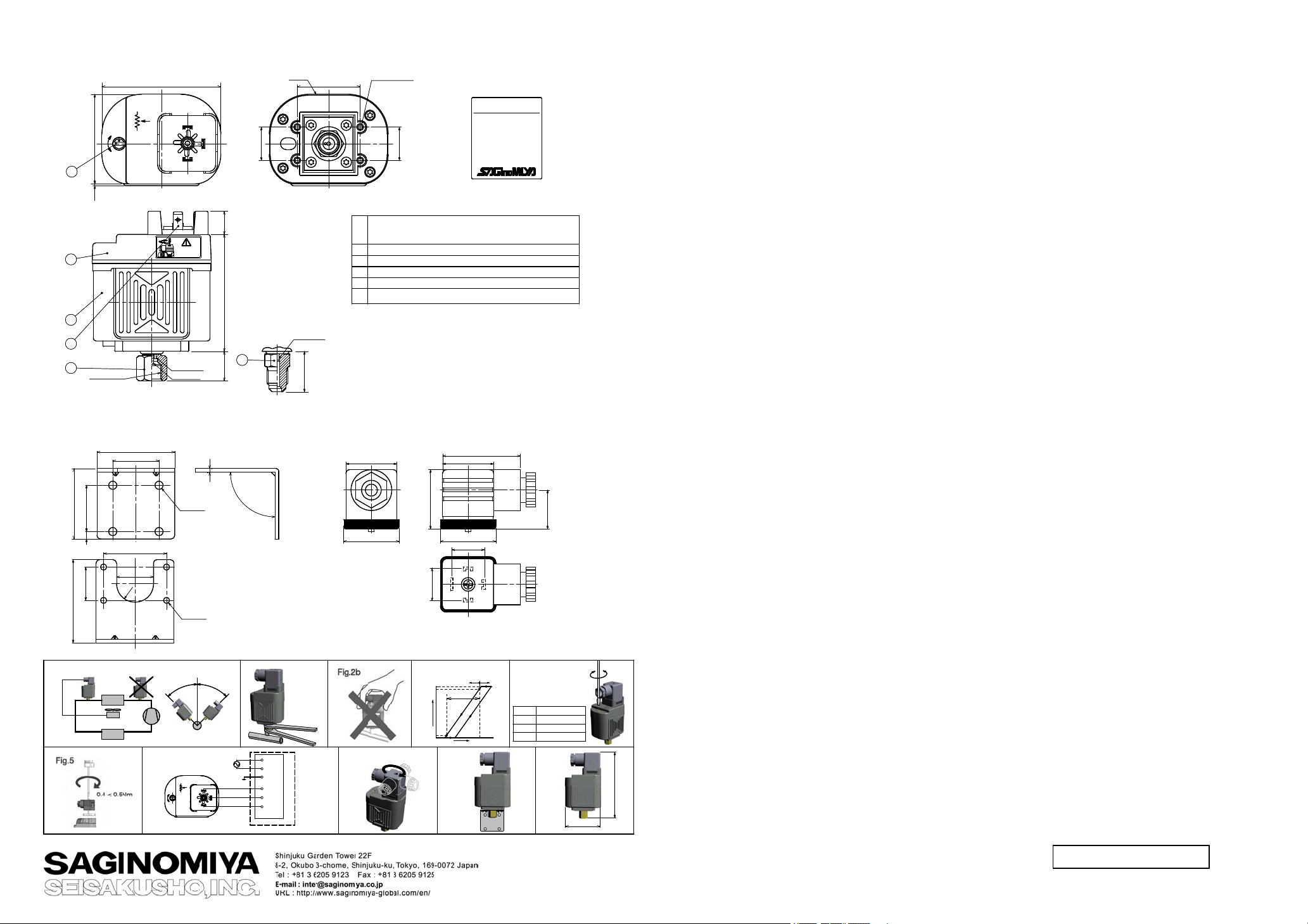
DIMENSIONS
DIMENSIONS
1
1
(1) (48.4)
(1) (48.4)
2
2
3
3
4
4
5
5
7/16-20UNF
7/16-20UNF
+
+
-
-
2
2
1
1
1:+ 10V DC
1:+ 10V DC
2:GND
2:GND
3:0-10V DC
3:0-10V DC
±0.3
±0.3
64.2
64.2
3
3
SEE INSTRUCTIONS
SEE INSTRUCTIONS
2
2
1
1
Rated Torque
Rated Torque
:
:
[Nm]
[Nm]
0,4~0,6
0,4~0,6
Pressure
Pressure
admission
admission
port
port
Schrader
Schrader
Label
Label
34 ±0.3
34 ±0.3
3
3
(15.9) 63.2 12.5
(15.9) 63.2 12.5
5
5
14
14
Case of
Case of
XGE-*SEB*-* type
XGE-*SEB*-* type
Pressure
Pressure
admission
admission
port
port
(22)
(22)
4-φ2.6 Hole
4-φ2.6 Hole
XGE-AE01(Mounting bracket)
XGE-AE01(Mounting bracket)
for mounting screws
for mounting screws
MADE IN JA PAN
MADE IN JAPAN
18 ±0.3
18 ±0.3
7/16-20UNF Female Flare Fitting with Schroeder
7/16-20UNF Female Flare Fitting with Schroeder
⑤
⑤
7/16-20UNF Male Flare Fitting
7/16-20UNF Male Flare Fitting
Fasten terminal
④
Fasten terminal
④
Case
③
Case
③
Cover
②
Cover
②
Range adjusting screw
Range adjusting screw
①
①
No.
No.
or
or
Parts Name
Parts Name
FAN SPEED CONTROLLER
FAN SPEED CONTROLLER
EC
EC
TYPE:XGE-2SE
TYPE:XGE-2SE
LOT No.:2017
LOT No.:2017
Supply voltage:10VDC
Supply voltage:10VDC
Output voltage:0-10VDC
Output voltage:0-10VDC
Setting:8bar
Setting:8bar
RANGE:8 t o 18bar
RANGE:8 t o 18bar
[116 to 261Psi]
[116 to 261Psi]
Label
Label
CONDENSER
CONDENSER
Option
Option
Mounting Bracket(XGE-AE01)
Mounting Bracket(XGE-AE01)
38
38
25 ±0.24
25 ±0.24
18
18
38
38
42
42
25 ±0.2
25 ±0.2
34
34
20
20
0
0
1
1
R
R
+
+
-
-
2
2
4-φ4.4
4-φ4.4
For wall mounting
For wall mounting
4-φ3.2
4-φ3.2
For XGE mounting
For XGE mounting
Fig.1bFig.1a
Fig.1bFig.1a
4
4
5
5
゚
゚
゚
゚
5
5
4
4
2
2
3
3
2
2
1
1:+ 10V DC
1:+ 10V DC
2:GND
2:GND
3:0-10V DC
3:0-10V DC
1
1
1
SEE INSTRUCTIONS
SEE INSTRUCTIONS
0-10V
0-10V
3
3
+10V
+10V
Accessory (Furnished)
Accessory (Furnished)
Plug
Plug
27.5 27.5
27.5 27.5
9
9
0
0
゚
゚
30 30
30 30
Fig.2a
Fig.2a
Fig.7
L
L
N
N
PE
PE
GND
GND
GND
GND
INPUT
INPUT
OUTPUT
OUTPUT
TERMINAL
TERMINAL
EC FAN MOTOR
EC FAN MOTOR
Fig.7
10V
10V
95%(9.5V)
95%(9.5V)
5%(0.5V)
5%(0.5V)
32
32
18
18
Output Voltage
Output Voltage
0V
0V
Fig.3
Fig.3
E.P.B
E.P.B
(Fixed)
(Fixed)
42
42
18
18
F.V.S.(Adjustable)
F.V.S.(Adjustable)
Pressure
Pressure
Range
Range
8~18
8~18
10~25
10~25
22~39
22~39
Fig.4
Fig.4
Approx.0.8bar
Approx.0.8bar
Approx.1.5bar
Approx.1.5bar
Approx.2.5bar
Approx.2.5bar
Fig.9Fig.8Fig.6
Fig.9Fig.8Fig.6
21
21
-
-
+
+
360°
360°
113.6
113.6
64.2
64.2
XGE-X1E MAR.2017
XGE-X1E MAR.2017
REFERENCE DRAWING
REFERENCE DRAWING
 Loading...