

Page 1

Data sheet
Gasketed heat exchanger XG
Description / application
The XG is a heat exchanger with gaskets and it
has been developed for use with district heating
and cooling systems. The heat exchangers can
be opened for cleaning and for replacement
of plates and gaskets. The XG plate heat
exchangers with gaskets are manufactured with
dierent plate sizes.
Main data:
- Min. temperature -10 °C
- Max. temperature +150 °C
- Max. working pressure 16 bar
- Circulation water / glycolic water up to 50%
- Connection size DN (thread or anged)
25…125
Approvals:
• Pressure Equipment Directive (PED) 97/23/EC
• GOST/Russia
DEN-SMT/SI
VD.KA .F6.02 © Danfoss 09/ 2014
1
Page 2

Gasketed heat exchanger, XGData sheet
Ordering Explanation, XG types
XG 10L – 1 – 10
Plate types L - H
Number of plates
Pass of the heat exchanger
1 = 1-pass
Plate type
Plate size
G=Gasketed heat exchanger
Special versions for dierent mediums,
connections / couplings, max. operating
pressures, materials and capacities are available
on request. Please contact the local sales
representative for details.
The heat exchanger can consist of plates type L
or plates type H.
The H- type plate has larger herring bone angle
than the L- type plate. H- type plate ts better
for certain temperatures than L- type. H- type
heat exchangers have better heating capacity,
but they also have higher pressure loss.
L- type H- type
The same principal dierence can be obtained with
other plate patterns as well.
Gasketed heat exchangers type XG
Typ e XG 10 -1 XG 14H-1 XG18 H-1 XG 20L-1 XG 20 H-1
Thread Thread Thread Thread Thread
Connection
G 1 A G 1¼ A G 1¼ A G 2 A G 2 A
No of plates, n
8 - 00 4B126 0 004B1276 - 10 004B5005 00 4B1261 00 4B1277 004B2954 004B5205
20 004B5010 004 B1262 004B1278 004B2955 004 B5210
30 004B5015 004 B1263 004B1279 004B2956 004B5215
40 004B5020 00 4B126 4 0 04B1280 004B2957 004B5220
50 004B5025 004B1265 0 04B1281 004B2958 004B5225
60 004B5030 0 04B1266 004 B1282 004B2959 004B5230
70 004B5035 004 B1267 004 B1283 004B2960 004B5235
80 - 004B1268 0 04B12 84 004 B2961 004B5240
90 - 00 4B1269 004 B1285 004B2962 004B5245
100 - 004 B1270 004 B1286 004B2963 004B5250
110 - 00 4B1271 00 4B1287 004B2964 004B5255
120 - 0 04B1272 004B128 8 004B2965 004B5260
130 - - - - 140 - - - 004B2966 004B5270
150 - - - - 160 - - - - 180 - - - - 200 - - - - -
* Available on request
¹ Primary / secondary
XG 31L-1 XG 31H-1 XG 40-1 XG 50 -1 XG 60 -1* XG 70 -1*
Flange Flange
DN 65 DN 65
- - - - - -
00 4B1375 00 4B1389 - - - -
004B1376 004B1390 - - - -
00 4B1377 004 B1391 - - - -
00 4B1378 004 B1392 - - - -
004B379 0 04B1393 004B1045 004B1091 - -
00 4B138 0 0 04B13 94 004B1046 004B1092 - -
00 4B1381 00 4B1395 004B1047 004B10 93 - -
004B1382 0 04B1396 004B1049 004B1094 - -
00 4B1383 004B1397 004B1083 004B1095 - -
00 4B138 4 0 04B1398 004 B1084 004B1096 - -
004B1385 0 04B1399 0 04B1085 004B1097 - -
00 4B138 6 004B1400 004B1086 0 04B1098 - -
00 4B1387 004B1401 - - - -
00 4B138 8 0 04B14 02 004B1087 00 4B1099 - -
- - - - - -
- - 004 B1088 004B1100 - -
- - 004 B1089 004B1101 - -
- - 004B1090 0 04 B1102 - -
Place for
ange
DN
100/125¹
Place for
ange
DN
100/125¹
- -
2
VD.KA .F6.02 © Danfoss 09/ 2014
DEN-SMT/SI
Page 3
Data sheet
Gasketed heat exchanger, XG
Accessories Accessories for gasketed heat exchanger type XG
Typ e Code No.
Gasket (set of 10) Plates (set of 10) Special plate set¹ Special plate set
XG 10 004B 6931³ 004B6938 004B2930 00 4B2931
XG 14 H 004B1301 0 04B13 03 00 4B130 9 004 B1311
XG 18H 0 04B1302 004B1304 004 B1310 0 04B1312
XG 20L
XG 20H 004B6939 004B2932 004B2933
XG 31L
XG 31H 00 4B1370 004B1404 0 04B14 07
XG 40 004B6934 004B69 41 004B2936 004B2937
XG 50 004B6935 004B6942 004B2938 004B2939
XG 60 004B6936 004B6943 004B2940 004B29 41
XG 70 004B6937 004B6944 004B2942 004B2943
¹ The set contains front plate, end plate and matching gaskets for 1-pass versions
² The set contains front plate, end plate, middle plate and matching gaskets for 2-pass versions
³ Non-glued gasket
Clip-on gasket
Glued gasket
Min. order size 10 pieces = 1 set (I-pack). Sets of 250 pieces available on inquiry.
004B6932
00 4B1367
004B2967 004B2968 004B2969
004B1368 0 04B14 03 004B1406
2-pass ²
Tailpieces for gasketed heat exchanger type XG
Description Suitable for Connection Code No.¹
XG10
Solder tailpieces
Weld-on tailpieces
Threaded tailpieces XG10
¹ One set contains 2 tailpieces with unionnuts and gaskets
XG14, XG18
XG20
XG10
XG14, XG18
XG20
G 1 A / 15 mm 004B2904
G 1 A / 18 mm 004B2905
G 1 A / 22 mm 004B2906
G 1 ¼ A /
22mm, 28 mm
G 2 A / 28 mm 004B2910
G 2 A / 35 mm 0 04 B2911
G 2 A / 42 mm 0 04B2912
G 1 A / DN 15 004B2901
G 1 A / DN 20 003H6909
G 1 A / DN 25 004B2903
G 1¼ A / DN 25 003H6910
G 1¼ A / DN 32 004B1343
G 2 A / DN 32 004B2907
G 2 A / DN 40 004B2908
G 2 A / DN 50 004B2909
G 1 A / G 3/4 A 00 4B2913
- -
00 4B1358
DEN-SMT/SI
VD.KA .F6.02 © Danfoss 09/ 2014
3
Page 4

Accessories continued
Gasketed heat exchanger, XGData sheet
Insulation for gasketed heat exchanger type XG
Typ e XG 10-1 XG 14H-1 XG 18H-1
No of plates
8 10
20 - 30 - 40
50
60
70 00 4B5135
90 -
100 -
120 130 - - - 140 - - - 004B5370 004B5790 004B5990
150 - - - - - - 160 - - - - 180 - - - - 200 - - - - - 004B5799 004B5999
004B5115 00 4B5315 004 B1361
00 4B5130 004B1314 004B1319 004B5330 004 B1362
00 4B1338 004B1318
00 4B1315 00 4B1320 004B5345 0 04B1363 0 04B5745 004B594580 -
004B1316 004B1321 004B5360 00 4B1365 004B5760 004B5960110 -
XG 20 L-1
XG 20 H-1
- - - -
XG 31L-1
XG 31H-1
00 4B136 6
XG 40 -1 XG 50 -1
- -
- -
004B5730 004B5930
- -
004B5790 004B5790
Insulation properties
Technical data
Typ e Coated steel sheet and polyester insulation
Heatconductivity, λ [W/mK] 0.042
Max temperature, °C
-Permanent, °C 150
-Short term peak, °C 180
Wall thickness, mm 30
Typ e XG 10 -1 XG 14H -1 XG 18 H-1
Max. working pressure
(bar)
Max. operating temp. (°C) 150
Min. operating temp.² (°C) -10
Flow medium Circulation water / glycolic water up to 50%
Volume/channel (litres) 0.045 0.095 0.13 0.480 0.370 1. 370 1.710
Heat surface, m²/plate 0.021 0.049 0. 074 0.122 0.141 0.288 0.383
Connection type Thread³ Flange, DN Place for ange, DN
Connection size G 1 A G 1¼ A G 1¼ A G 2 A DN 65 DN 100/125
Plate material Stainless steel, mat. no. EN 1.4404
Gasket material, rubber EPDM
¹ PN25 versions are available on inquiry. PN25 versions must be ordered separately using special codes,
please contact your sales representative.
² At flow temp. below 2 °C glycolic water must be used
³ Cylindrical external thread acc. to DIN ISO 228/1
Flanges PN16, acc. to EN 1092, facing type B (B1)
Primary side / Secondary side
XG 20 L-1
XG 20 H-1
16 / (25)¹
XG 31L-1
XG 31H-1
XG 40 -1 XG 50-1
4
VD.KA .F6.02 © Danfoss 09/ 2014
DEN-SMT/SI
Page 5

Data sheet
Gasketed heat exchanger, XG
Technical data continued
Design and function
Heat exchanger water volume
Primary side Secondary side
(n/2-1) * volume/channel
n = number of plates
XG 14..., XG 18...,XG 20 .., XG 31...,
XG 40..., XG 50...
1)
n/2* volume/channel
XG 10...
The heat exchangers are made of shapepressed heat plates between which the ow
channels are created. Gaskets between the
plates separate the ow channels from each
other so that the ows do not mix. The heavy
turbulence and counter-ow principle enables
ecient heat transfer. The task of the heat
exchanger is to transfer heat from the primary
to secondary ow through a heat transfer plate
thus preventing the ows from mixing with
each other.
Heat exchanger heat surface
(n-2) * heat surface/plate
1)
n= number of plates
1-pass heat exchanger
T11 - Primary side in
T12 - Primary side out
T21 - Secondary side in
T22 - Secondary side out
The plate heat exchanger with gaskets can
be opened for cleaning and for replacement
of plates and gaskets. A stepless output
adjustment can be carried out by changing the
number of plates.
The choice of heat exchanger is determined by
the desired heat output, required temperatures
and the permitted pressure losses.
Sizing Dimensioning and selection of heat exchangers
should be carried out with the support of
the Danfoss dimensioning program for heat
exchangers.
Mounting The heat exchanger must be mounted in vertical
position. Prepare the foundation for the heat
exchanger if necessary, always according to local
regulations. It is recommended that all pipes
connected to the heat exchanger are equipped
with shut-o valves for maintenance purposes.
The pipes to be connected must be mounted so
that the strain caused by the thermal expansion,
for instance, does not harm the heat exchanger.
The pipes must be equipped with brackets to
prevent any torsional stress concentration at the
heat exchanger’s pipe connections.
It is recommended that the heat exchanger is
equipped with insulation.
A safety valve must be installed between the
heat exchanger and the shut-o valves on the
secondary side of the heat exchanger. If the
safety valve is not installed, thermal expansion
of uid might destroy the heat exchanger when
the shut-o valves are closed.
DEN-SMT/SI
VD.KA .F6.02 © Danfoss 09/ 2014
5
Page 6

Gasketed heat exchanger, XGData sheet
Assembly dimensions
B
A
D
C
Example of XG40, XG50
Typ e A B C
XG10 158 100 15 9
XG14 200 92 12 10
XG18 200 92 12 10
XG20 300 234 20 13
XG31 360 234 20 13
XG40 540 430 30 20
XG50 540 430 30 20
View from above
Mounting bracket
End rear
Plate pack
End front
XG20, XG40, XG50, XG31
Number
of plates
8 - 118 118 - - 10 103,5 123 123 491 495 - 20 129 146 14 6 491 645 - 30 154,5 169 169 491 645 - 40 18 0 192 192 641 645 - 50 205,5 215 215 641 795 850 850
60 231 238 238 641 795 850 850
70 256,5 261 261 791 795 950 950
80 - 284 284 791 795 1150 1150
90 - 307 307 791 945 115 0 115 0
100 - 330 330 9 41 945 1150 1150
110 - 353 353 941 945 1150 1150
120 - 376 376 9 41 1095 1350 135 0
130 - - - - 1095 - 140 - - - 1091 1095 1350 1350
150 - - - - - - 160 - - - - - 1650 1650
180 - - - - - 1650 1650
200 - - - - - 1650 1650
XG10 XG14 XG18 XG20 XG31 XG40 XG50
Mounting bracket
XG10, XG14, XG18
Dimension-D mm
Dimensions
6
Typ e Connection
XG 10-… G 1 A
XG 14H-... G 1¼ A
XG 18H-... G 1¼ A
XG 20L-...
XG 20H-...
XG 31L-.. .
XG 31H-...
G 2 A
DN 65
External dimensions [mm]
A B C D G H F L
1)
2.55*n 158 65 235 310 A+30 460 500 0.2*n+16
1)
2.4*n 200 80 430 560 A+60 675 550 0.34*n+52
1)
2.4*n 200 80 630 760 A+60 875 550 0.46*n+72
1)
3.5*n 300 140 640 835 A+60 910 130 0 0.8*n+125
2)
2.95*n 360 150 665 910 A+60 965 160 0
max
Weight
empty
1.22*n+170
XG 40-… DN 100/125²) ³ 4.25*n 540 240 856 1198 A+10 0 1238 2500 2.2*n+550
)
XG 50-… DN 100/125²
³ 4.25*n 540 240 1096 1438 A+10 0 1478 2500 2.8*n+675
n = number of plates
L
max= Length of a heat exchanger with maximum number of heat plates
1)
Cylindrical external thread acc. to DIN ISO 228/1
2)
Flanges PN16, acc. to EN 1092, facing type B (B1)
³ Primary side / Secondary side
VD.KA .F6.02 © Danfoss 09/ 2014
[kg]
DEN-SMT/SI
Page 7

Data sheet
n
k
d₃
Gasketed heat exchanger, XG
Dimensions continued
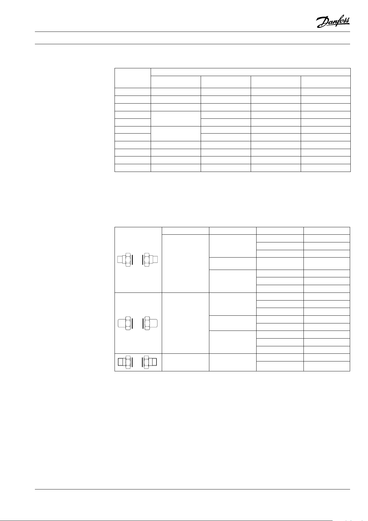
Solder tailpieces Weld-on tailpieces Threaded tailpieces
G G 1 A G 1 ¼ A G 2 A
SW mm 41 47 71
1)
G
d
d
1
L2 117 - - - - -
- G ¾A - - - - - - 21,3 (DN 15) 26,9 (DN 20) 33,5 (DN 25) 33,5 (DN 25) 42,4 (DN 32) 42,4 (DN 32) 48,5 (DN 40) 60,3 (DN 50)
15 18 22 22 28 28 35 42
mm
L3 117 117 117 90 90 175 175 175
L4 117 117 117 90 90 175 175 175
1)
Cylindrical external thread acc. to DIN ISO 228/1
Flange connection
Flange dimensions
d₂
DN 65 10 0 125
L1¹
k 145 180 210
d
mm
2
n 4 8 8
d
3
1)
Flanges PN16, acc. to EN 1092, facing type B (B1)
2)
Primary / secondary
200/100² Place for ange Place for ange
18 18 18
M16 M16
Place for ange
DEN-SMT/SI
VD.KA .F6.02 © Danfoss 09/ 2014
7
Page 8

Gasketed heat exchanger, XGData sheet
Dimensions continued
Insulation for gasketed heat exchanger type XG
Typ e XG 10-1 XG 14H-1 XG 18 H-1
F (mm) 490 705 905 940 980 124 8 1488
B (mm) 218 260 260 360 420 600 600
No of plates H (mm)
8 10
20 - 30 - 40
50
60
70 272
90 -
100 -
120 130 - - - 140 - - - 610 925
150 - - - - - - 160 - - - - 180 - - - - 200 - - - - - 1010
168 225 203
246 264 330 285
192
336 435 368 54380 -
408 540 450 670110 -
XG 20 L-1
XG 20 H-1
- - - -
XG 31L-1
XG 31H-1
505
XG 40 -1 XG 5 0-1
- -
- -
415
- -
925
8
VD.KA.F6.02
Produce d by Danfoss A/S © 09/2014
 Loading...