

Page 1
XDBKITS4 Bus / DB Terminal Kit
(Size 4)
Installation Manual
DPD00115
Page 2

Need Help?
This manual answers most installation and startup questions
that may arise. However, if you have any problems,
please let your first call be to us.
Vacon, Inc.
Chambersburg, PA 17202
Normal business hours:
(North America)
8:00 AM to 5:00 PM, Eastern time
+1 877-Vacon06
(+1 877-822-6606)
After-hours support is also available
and Vacon, Inc. are trademarks of Vacon Plc, a member of Vacon Group.
All other product names are trademarks of their respective companies.
Copyright 2009, Vacon, Incorporated. All rights reserved.
Page 3
XDBKITS4 Option Kit Installation Manual vacon 3
Installing the Bus / DB Terminal Option Kit
Introduction
The XDBKITS4 option kit is designed to allow the Size 4 X4 and X5 AC drives to be easily adapted to install either
external DB resistors or to interconnect the DC bus terminal with another controller. Inc lud ed in that Size 4 category
are the following X4 and X5 drive models:
X4 AC Drive Model No. X5 AC Drive Model No.
X4C40600C X5C40600C
X4C40750C X5C40750C
X4C41000C X5C41000C
X4C50600C X5C50600C
X4C50750C X5C50750C
X4C51000C X5C51000C
Applicable Documents
This manual is supplied as a supplement to the X4 AC Drive User’s Manual (DPD 00088; previously Form 1428), and
the X5 AC Drive User’s Manual (DPD 00089; previously Form 1434).
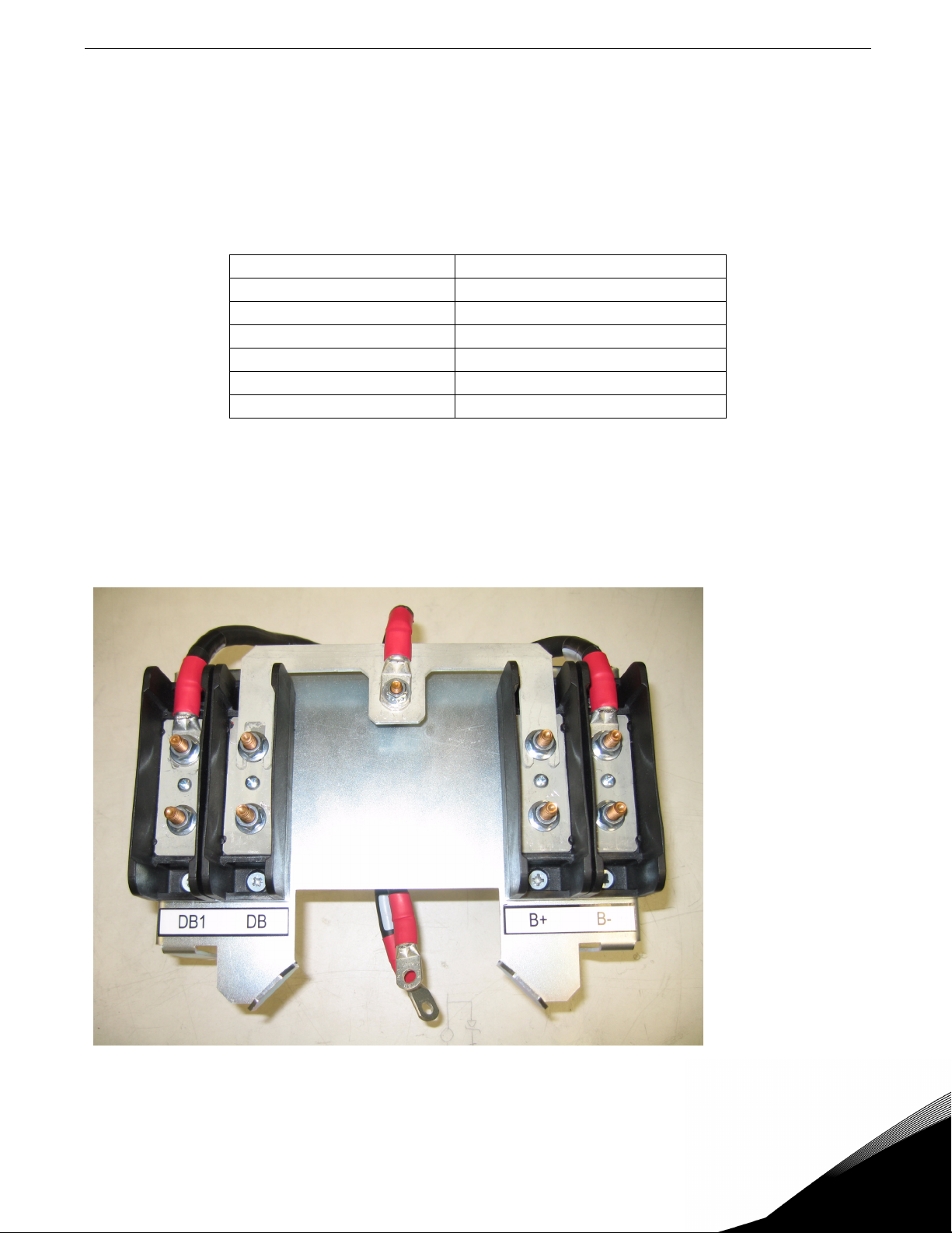
Option Kit Contents
The option kit is illustrated in Figure 1:
Figure 1: The XDBKITS4 option kit
Email: usa@vacon.com • Fax 717-264-3115
Page 4

4 vacon XDBKITS4 Option Kit Installation Manual
Installation Procedures
!
WARNING
SENSITIVE EQUIPMENT
This assembly contains static-sensitive components. It should be handled only by a static-safe installer,
using a grounded wrist strap.
Failure to observe this precaution may cause premature equipment failure.
!
DANGER
HAZARDOUS VOLTAGE
• Disconnect all power before servicing a drive unit or its components. WAIT 5 MINUTES until the DC
bus capacitors discharge.
• Ensure that any other power sources that may feed control logic have been disconnected.
• DO NOT short across DC bus capacitors or touch unshielded components or terminal strip screw
connections with voltage present.
• Install all covers before applying power or starting and stopping the drive.
• The user is responsible for conforming to all applicable code requirements with respect to grounding
all equipment.
• Many parts in a drive, including printed circuit boards, operate at line voltage. DO NOT TOUCH. Use
only electrically-insulated tools.
Before servicing any drive.
• Disconnect all power.
• Place a “DO NOT TURN ON” label on the drive disconnect.
• Lock the disconnect in the open position.
Failure to observe these precautions will cause shock or burn, resulting in severe personal injury
or death.
Step 1.
Open the enclosure door by unthreading the door screws in eight places. Lift and rotate the door into the open
position.
24-hour support 1-877-822-6606
Page 5

XDBKITS4 Option Kit Installation Manual vacon 5
Step 2.
Remove the two M4 screws (see Figure 2) from the internal fan bracket and lower the fan assembly out of the way.
Ensure that the fan leads are not damaged or disconnected.
Figure 2: Removing the M4 screws from the assembly
Step 3.
Remove the nuts, washers, and
identification tags from the connections
labeled B-, B+, and DBC (see Figure 3).
Retain these pieces (except for the ID tags)
for later use during the reassembly of the
option kit.
Disconnect and insulate the AWG16 black
wire connected to the DBC terminal, as this
will no longer be used in external resistor
applications.
Figure 3: Location of DBC, B-, B+ connections
Email: usa@vacon.com • Fax 717-264-3115
Page 6

6 vacon XDBKITS4 Option Kit Installation Manual
Step 4.
Loosen the four M5 nuts located on threaded studs in the base of the enclosure (see Figure 4). Do not fully remove
the nuts, as that will make reassembly more difficult.
Figure 4: Location of the M5 nuts
Step 5.
Remove the cable marked DBC from the
terminal block of the option kit. Fasten one
end of the DBC cable to the threaded stud,
using one nut and washer removed during
Step 3.
See Figure 5 for cable routing.
Use a maximum torque of 26 in-lbs.
Figure 5: DBC cable routing
24-hour support 1-877-822-6606
Page 7

XDBKITS4 Option Kit Installation Manual vacon 7
Step 6.
Insert the terminal bracket with B- and B+
leads into the drive enclosure. Fasten it to the
studs that had nuts previously loosened in
Step 4. When fastening the bracket, use a
maximum torque of 26 in-lbs. See Figure 7.
Figure 6: DBC cable routing
Step 7.
.Attach B- and B+ cables to standoffs.
(See Figure 3 on page 5 for the correct
connection location.) When fastening
the cables, use a maximum torque of
26-50 in-lbs.
Step 8.
Fasten the DBC cable to the bus bar
stud. Tighten the washer and nut
assembly using a maximum torque of
50 in-lbs. See Figure 7.
Figure 7: Fastening the DBC cable
Step 9.
Re-install the internal fan bracket assembly, tightening the two M4 screws to 12 in-lbs.
Step 10.
Close the door and tighten the cover screws to a maximum of 26 in-lbs.
Email: usa@vacon.com • Fax 717-264-3115
Page 8

head office and production:
Vaasa
Vacon Plc
Runsorintie 7
65380 Vaasa
firstname.lastname@vacon.com
telephone: +358 (0)201 2121
fax: +358 (0)201 212 205
production:
Suzhou, China
Vacon Suzhou Drives Co. Ltd.
Building 11A
428# Xinglong Street, SIP
Suchun Industrial Square
Suzhou 215126
telephone: + 86 512 62836630
fax: + 86 512 62836618
Naturno, Italy
Vacon S.R.I
Via Zone Industriale, 11
39025 Naturno
sales companies and representative offices:
production:
Chambersburg, USA
3181 Black Gap Road
Chambersburg, PA 17202
TB Wood's (India) Pvt. Ltd.
#27, 'E' Electronics City
Hosur Road
Bangalore - 560 100
India
Tel. +91-80-30280123
Fax. +91-80-30280124
finland
Helsinki
Vacon Plc
Äyritie 8
01510 Vantaa
telephone: +358 (0)201 212 600
fax: +358 (0)201 212 699
Tampere
Vacon Plc
Vehnämyllynkatu 18
33580 Tampere
telephone: +358 (0)201 2121
fax: +358 (0)201 212 750
australia
Vacon Pacific Pty Ltd
5/66-74, Micro Circuit
Dandenong South, VIC 3175
telephone: +61 (0)3 9238 9300
fax: +61 (0)3 92389310
austria
Vacon AT Antriebssysteme GmbH
Aumühlweg 21
2544 Leobersdorf
telephone: +43 2256 651 66
fax: +43 2256 651 66 66
belgium
Vacon Benelux NV/SA
Interleuvenlaan 62
3001 Heverlee (Leuven)
telephone: +32 (0)16 394 825
fax: +32 (0)16 394 827
brazil
Vacon Brazil
Alameda Mamoré, 535
Alphaville - Barueri -SP
Tel. +55 11 4166-5707
Fax. +55 11 4166-5567
canada
Vacon Canada
221 Griffith Road
Stratford, Ontario N5A 6T3
telephone: +1 (519) 508-2323
fax: +1 (519) 508-2324
china
Vacon Suzhou Drives Co. Ltd.
Beijing Branch
A528, Grand Pacific Garden Mansion
8A Guanghua Road
Beijing 100026
telephone: + 86 10 51280006
fax: +86 10 65813733
czech republic
Vacon s.r.o.
Kodanska 1441/46
110 00 Prague 10
telephone: +420 234 063 250
fax: +420 234 063 251
france
Vacon France
ZAC du Fresne
1 Rue Jacquard - BP72
91280 Saint Pierre du Perray CDIS
telephone: +33 (0)1 69 89 60 30
fax: +33 (0)1 69 89 60 40
germany
Vacon GmbH
Gladbecker Strasse 425
45329 Essen
telephone: +49 (0)201 806 700
fax: +49 (0)201 806 7099
Vacon OEM Business Center GmbH
Industriestr. 13
51709 - Marienheide
Germany
Tel. +49 02264 17-17
Fax. +49 02264 17-126
india
Vacon Drives & Control Plc
Plot No 352
Kapaleeshwar Nagar
East Coast Road
Neelangarai
Chennai-600041
Tel. +91 44 244 900 24/25
italy
Vacon S.p.A.
Via F.lli Guerra, 35
42100 Reggio Emilia
telephone: +39 0522 276811
fax: +39 0522 276890
the netherlands
Vacon Benelux BV
Weide 40
4206 CJ Gorinchem
telephone: +31 (0)183 642 970
fax: +31 (0)183 642 971
norway
Vacon AS
Bentsrudveien 17
3080 Holmestrand
telephone: +47 330 96120
fax: +47 330 96130
romania
Vacon Romania - Reprezentanta
Cuza Voda 1
400107 Cluj Napoca
Tel. +40 364 118 981
Fax. +40 364 118 981
russia
ZAO Vacon Drives
Ul. Letchika Babushkina 1,
Stroenie 3
129344 Moscow
telephone: +7 (495) 363 19 85
fax: +7 (495) 363 19 86
ZAO Vacon Drives
2ya Sovetskaya 7, office 210A
191036 St. Petersburg
telephone: +7 (812) 332 1114
fax: +7 (812) 279 9053
slovakia
Vacon s.r.o. (Branch)
Seberiniho 1
821 03 Bratislava
Tel. +421 243 330 202
Fax. +421 243 634 389
spain
Vacon Drives Ibérica S.A.
Miquel Servet, 2. P.I. Bufalvent
08243 Manresa
telephone: +34 93 877 45 06
fax: +34 93 877 00 09
sweden
Vacon AB
Anderstorpsvägen 16
171 54 Solna
telephone: +46 (0)8 293 055
fax: +46 (0)8 290 755
thailand
Vacon South East Asia
335/32 5th-6th floor
Srinakarin Road, Prawet
Bangkok 10250
Tel. +66 (0)2366 0768
ukraine
Vacon Drives Ukraine (Branch)
42-44 Shovkovychna Str.
Regus City Horizon Tower
Kiev 01601, Ukraine
Tel. +380 44 459 0579
Fax +380 44 490 1200
united arab emirates
Vacon Middle East and Africa
Block A, Office 4A 226
P.O.Box 54763
Dubai Airport Free Zone
Dubai
Tel. +971 (0)4 204 5200
Fax: +971 (0)4 204 5203
united kingdom
Vacon Drives (UK) Ltd.
18, Maizefield
Hinckley Fields Industrial Estate
Hinckley
LE10 1YF Leicestershire
telephone: +44 (0)1455 611 515
fax: +44 (0)1455 611 517
united states
Vacon, Inc.
3181, Black Gap Road
Chambersburg, PA 17202
telephone: +1 (877) 822-6606
fax: +1 (717) 267-0140
 Loading...