

Page 1
Technical Information
D Series and XD Series
Fixed Displacement Gear Pumps
www.danfoss.com
Page 2
Technical Information
D Series and XD Series Gear Pumps
Revision history Table of revisions
Date Changed Rev
April 2020 Corrected XD Model Code Information 0202
December 2019 0201
October 2019 First edition 0101
2 | © Danfoss | April 2020 BC319684134607en-000202
Page 3

Technical Information
D Series and XD Series Gear Pumps
Contents
General Information
Overview..............................................................................................................................................................................................6
Features and benefits..................................................................................................................................................................... 6
Quick chart overview...................................................................................................................................................................... 6
Typical applications.........................................................................................................................................................................7
Design...................................................................................................................................................................................................7
System schematic.............................................................................................................................................................................8
Product features................................................................................................................................................................................9
Technical Specifications
Technical specifications...............................................................................................................................................................10
Fluid specifications........................................................................................................................................................................10
Inlet pressure...................................................................................................................................................................................10
Operating Parameters
Sizing equations.............................................................................................................................................................................11
Pressure............................................................................................................................................................................................. 11
Temperature and viscosity......................................................................................................................................................... 12
Speed..................................................................................................................................................................................................12
Hydraulic fluid.................................................................................................................................................................................13
Filtration............................................................................................................................................................................................ 13
Filters.............................................................................................................................................................................................13
Selecting a filter.........................................................................................................................................................................13
Reservoir...................................................................................................................................................................................... 13
Line sizing......................................................................................................................................................................................... 14
Pump life........................................................................................................................................................................................... 14
Pump shaft connection................................................................................................................................................................14
Radial and axial loading...............................................................................................................................................................15
D Series Model Code
Single pump order code..............................................................................................................................................................16
DE1: D series cast iron gear pump, single section........................................................................................................ 16
A Rotation - viewed from drive shaft........................................................................................................................... 16
B1 Displacement..................................................................................................................................................................16
B2 Input shaft........................................................................................................................................................................17
C Mounting flange..............................................................................................................................................................17
D Rear cover: Port options, integrated valves, and auxillary flange................................................................. 18
E Flow control valve setting............................................................................................................................................ 19
F Pressure control valve setting.....................................................................................................................................20
H Assembly Screws - depending on rear cover........................................................................................................21
J Nameplates.........................................................................................................................................................................23
K Special feature.................................................................................................................................................................. 23
Two section (tandem) pump order code.............................................................................................................................. 23
A Rotation - viewed from drive shaft.................................................................................................................................23
B1 Displacement.......................................................................................................................................................................24
B2 Input shaft.............................................................................................................................................................................24
C Mounting flange................................................................................................................................................................... 25
R Ports - First section............................................................................................................................................................... 25
S Displacement - Second section........................................................................................................................................26
D Rear cover: Port options, integrated valves and auxillary flange........................................................................26
E Flow control valve.................................................................................................................................................................28
F Pressure control valve..........................................................................................................................................................29
H Assembly screws...................................................................................................................................................................30
J Nameplate................................................................................................................................................................................33
K Special features......................................................................................................................................................................33
Three section (triple) pump order code.................................................................................................................................33
A Rotation - viewed from drive shaft.................................................................................................................................34
B1 Displacement - First section........................................................................................................................................... 34
B2 Input shaft.............................................................................................................................................................................34
C Mounting flange................................................................................................................................................................... 35
L Ports - First section................................................................................................................................................................35
©
Danfoss | April 2020 BC319684134607en-000202 | 3
Page 4

Technical Information
D Series and XD Series Gear Pumps
Contents
M Displacement - Second section......................................................................................................................................36
R Ports - Second section.........................................................................................................................................................37
S Displacement - Third section............................................................................................................................................ 37
D Rear cover: Port options, integrated valves and auxiliary......................................................................................38
E Flow control valve.................................................................................................................................................................40
F Pressure control valve..........................................................................................................................................................40
H Assembly screws...................................................................................................................................................................41
J Nameplate................................................................................................................................................................................41
K Special feature........................................................................................................................................................................42
Four section (quad) pump order code...................................................................................................................................42
A Rotation - viewed from drive shaft.................................................................................................................................42
B1 Displacement - First section........................................................................................................................................... 43
B2 Input shaft.............................................................................................................................................................................43
C Mounting flange................................................................................................................................................................... 44
L Ports - First section................................................................................................................................................................44
M Displacement - Second section......................................................................................................................................45
N Ports - Second section........................................................................................................................................................ 45
P Displacement - Third section............................................................................................................................................46
R Ports - Third Section.............................................................................................................................................................47
S Displacement - Fourth section.........................................................................................................................................47
D Rear cover: Port options, integrated valves and auxiliary flange........................................................................48
E Flow control valve.................................................................................................................................................................50
F Pressure control valve..........................................................................................................................................................51
H Assembly screws...................................................................................................................................................................51
J Nameplate................................................................................................................................................................................52
K Special feature........................................................................................................................................................................52
D Series Options
Shaft options....................................................................................................................................................................................53
Mounting flanges...........................................................................................................................................................................54
Multiple pump port options...................................................................................................................................................... 56
Rear cover - port options.............................................................................................................................................................58
Integrated Priority Flow Divider..........................................................................................................................................62
Integrated Priority Flow Divider..........................................................................................................................................64
Integrated Steering Cover.....................................................................................................................................................64
Integrated Steering Cover.....................................................................................................................................................65
Load Sense Priority Flow Valve............................................................................................................................................66
Pumps with Load Sense Priority Flow Valves.................................................................................................................67
D Series Dimension Drawings
One Section - Single......................................................................................................................................................................69
Two section - Tandem..................................................................................................................................................................70
Three Section - Triple....................................................................................................................................................................71
Four Section - Quad...................................................................................................................................................................... 72
D Series Performance Data
Flow performance..........................................................................................................................................................................73
XD Model Code Information
A Rotation - viewed from drive shaft...................................................................................................................................... 78
B1 Displacement - front section............................................................................................................................................... 78
B2 Input shaft.................................................................................................................................................................................. 78
C Mounting flange.........................................................................................................................................................................79
R Ports - first section......................................................................................................................................................................79
S Displacement - rear section....................................................................................................................................................79
D Rear cover.....................................................................................................................................................................................79
E Flow control valve...................................................................................................................................................................... 80
F Pressure control valve...............................................................................................................................................................80
H Assembly screws........................................................................................................................................................................ 80
J Name plate.................................................................................................................................................................................... 80
K Special features...........................................................................................................................................................................80
4 | © Danfoss | April 2020 BC319684134607en-000202
Page 5

Technical Information
D Series and XD Series Gear Pumps
Contents
XD Options
XD Shaft options.............................................................................................................................................................................81
XD Mounting flanges....................................................................................................................................................................81
XD Dimension Drawings Information
Dimensions.......................................................................................................................................................................................84
©
Danfoss | April 2020 BC319684134607en-000202 | 5
Page 6
300
250
200
150
100
50
0
0
10
20
30 40 50
Displacement
cm
3
/rev
P
ressure
psi
P107 949E
Group 3 Gear Pump
D SERIES Cast Iron Gear Pump
Group 2 Gear Pump
Bar
in3/rev
4000
3000
2000
1000
0
1.0
0
3.0
3.0
4.0 5.0
6.0
60 70
80 90 100
Group 1 Gear Pump
XD SERIES Cast Iron Gear Pump
Technical Information
D Series and XD Series Gear Pumps
General Information
Overview
The D Series fixed displacement gear pump has been specifically designed for demanding mobile
equipment applications where maximum performance is required at peak power levels and operating
temperatures.
The design integrates cast iron construction with pressure balanced thrust plates to deliver consistent
efficiency across the entire operating range of pressure, speed, and temperature; all in an industryleading package size that maximizes power density.
Features and benefits
•
High strength cast iron construction allows consistently efficient performance and long life in
continuous operation at 276 bar [4000 psi] and peak conditions of 303 bar [4400 psi].
•
Custom engineered bearings, pressure-balanced load plates, and viton seals optimize internal
lubircation allowing for long life with intermittent fluid temperatures up to 115 °C [239 °F] and fluid
viscosities as low as 8 mm2/sec (cSt) [36 SUS].
•
Compact three-piece design maximizes power density and creates one of the shortest multisection
pumps (with up to four pumping sections) in the global marketplace.
•
Bearings located in the front flange increase radial/axial load carrying capability and eliminate the
need for most bolt-on outrigger bearings.
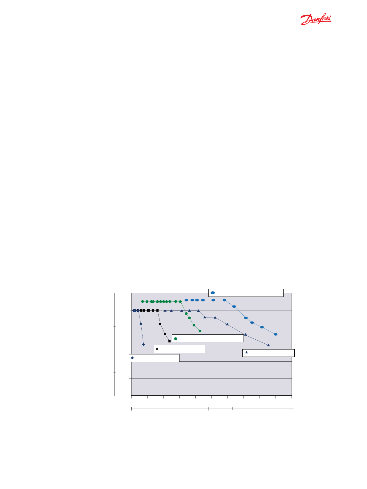
Quick chart overview
The D Series pump blends the traditional Group 2 (SAE-A) and Group 3 (SAE-B) frame sizes in a single
package with displacements from 7 to 45 cm3 (0.43 to 2.75 in3).
These displacements, in addition to a wide variety of shafts, flanges, ports, and integrated valve options
can be used in virtually any combination to offer greater design flexibility and meet specific application
requirements.
Gear pumps quick chart overview
6 | © Danfoss | April 2020 BC319684134607en-000202
Page 7
1
3
2
7
5
4
6
8
Technical Information
D Series and XD Series Gear Pumps
General Information
Typical applications
The D Series gear pump is commonly applied in the following type of applications:
•
Wheel loader - Aggressive duty cycles with continuous working pressures above 250 bar [3600 psi]
•
Mining equipment - Increased exposure to system contamination in a corrosive environment
•
Skid steer loaders - Multiple pump combinations with short length and common inlets
•
Work function attachments - Rapid loading of cylinders/motors in high bulk modulus systems
causing pressure rise rates greater than 3000 bar/sec
•
Agricultural sprayers - Pumps with integrated valves including priority flow dividers and load sense
steering
•
Pavers - D pumps integrated with other Turolla components including variable displacement piston
pumps, aluminum gear pumps and cartridge valves
•
Fan drives - High levels of performance with elevated temperatures and minimal oil viscosities and
restrictive envelope dimensions
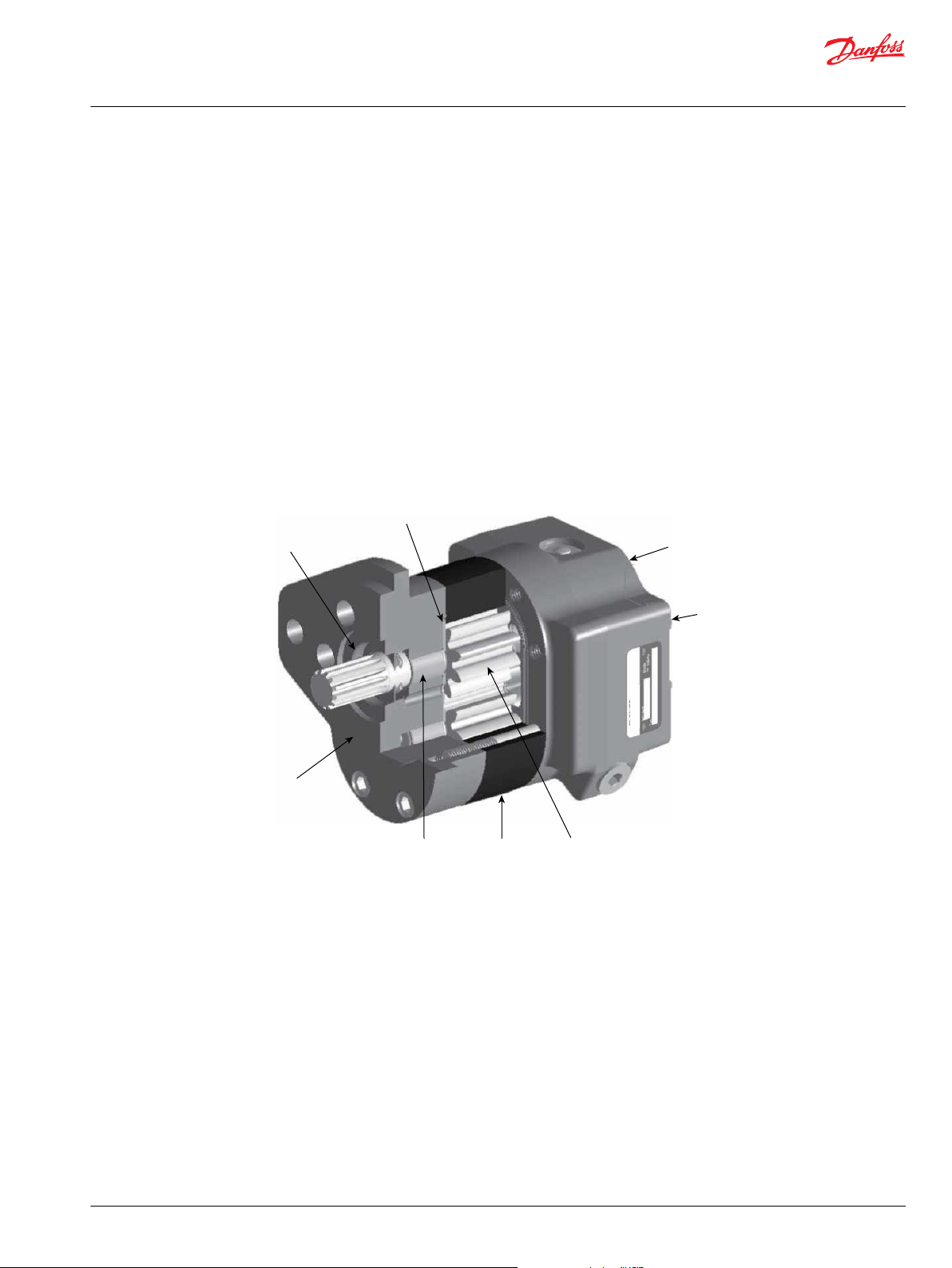
Design
1. High-quality, heat-treated alloy steel integral gears and shaft
2. High-strength ductile iron body and covers
©
Danfoss | April 2020 BC319684134607en-000202 | 7
3. Heavy-duty low-friction sleeve bushings
4. Pressure balanced bronze-on-steel thrust plates
5. High temperature Viton seals
6. Optional: flow control with load sensing priority flow or factory preset fixed priority flow divider valve
7. SAE-A/SAE-B 2-bolts mounting flange
8. Optional: Side or rear port options
Cast iron housings, bearings
The three piece structural members of the pump are made of high-strength cast ductile iron. Cast iron
provides contamination resistance, thermal stability and the strength needed for consistently high levels
of performance and durability needed in demanding off highway applications.
Heavy-duty low friction PTFE-lined sleeve bushings are optimized to provide long life in low viscosity,
high pressure conditions. The bearings are located in the front mounting flange, rear cover, and bearing
plate (for multiple section pumps) and allow the D pump to be 20% shorter than a typical bearing block
Page 8
Microcontroller
(PLUS+1TM)
Filter
T3
T2
T1
Temperature
sensors
D Series
gear pump
D Series
gear motor
RESERVOIR
DIESEL ENGINE
P107 929E
case drain
CANBUS J1939
Technical Information
D Series and XD Series Gear Pumps
General Information
design pump. In addition, the proximity of the front bearing to the mounting flange increases the radial
load capacity of the pump, eliminating the need for most bolt-on outrigger requirements.
Pressure balance, sealing
The pump incorporates two steel-backed bronze thrust plates seated in depressions in the mounting
flange, rear cover, and bearing plate (for multiple section pumps). Underneath the front plate (known as
the deflecting plate) is the load seal.
The E-shaped load seal distributes system pressure underneath the plate and enables the plate to deflect
and maintain a tight sealing surface against the side face of the gears.
The tight sealing action allows the pump to maintain very high levels of volumetric efficiency, even when
operating in extreme temperature, pressure and speed conditions.
One-piece gear design
All D Series pump gear shafts are of one-piece design. This enables the shaft to provide uniform high
strength and accurate gear profile relative to the journals for smooth mesh operation. The integral gear
shafts are made of heat treated AISI 8620 steel, manufactured to precise tolerances and surface finishes,
for maximal life and minimal leakage. This integral design eliminates the potential problems of fatigue
stress and gear face mismatch often associated with two-piece gear shaft designs.
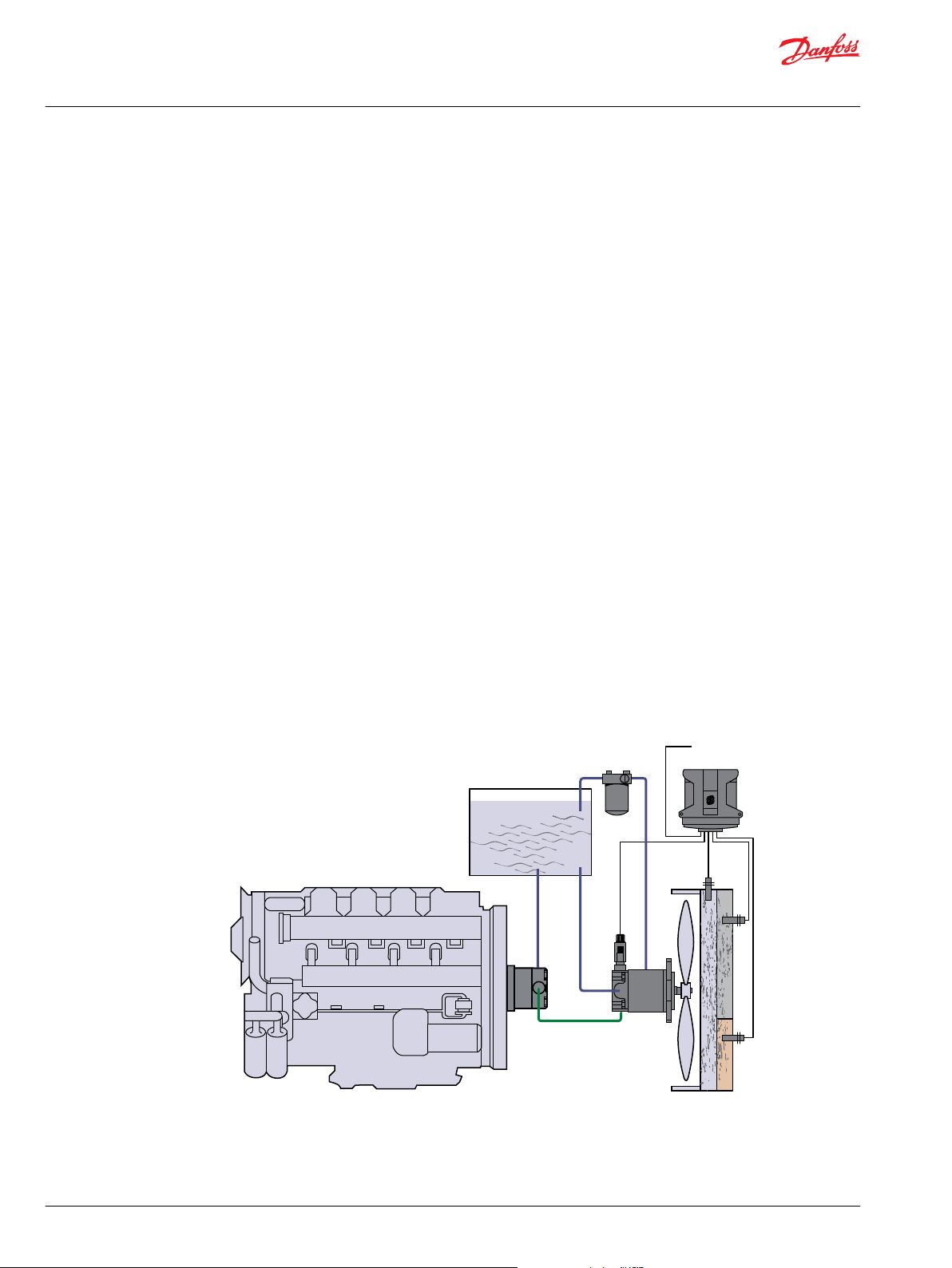
System schematic
Multiple pump configuration
D Series pumps can be coupled together to produce tandem, triple and even quadruple section units.
The interconnecting chambers accommodate fluid flow between sections and allow the number of inlet
connections to be minimized. Systems that require operation with different fluids and/or reservoirs can
be accommodated with sealed auxiliary covers between sections.
Gear Pump/Gear Motor Fan Drive System with Electronic Control
8 | © Danfoss | April 2020 BC319684134607en-000202
Page 9

Technical Information
D Series and XD Series Gear Pumps
General Information
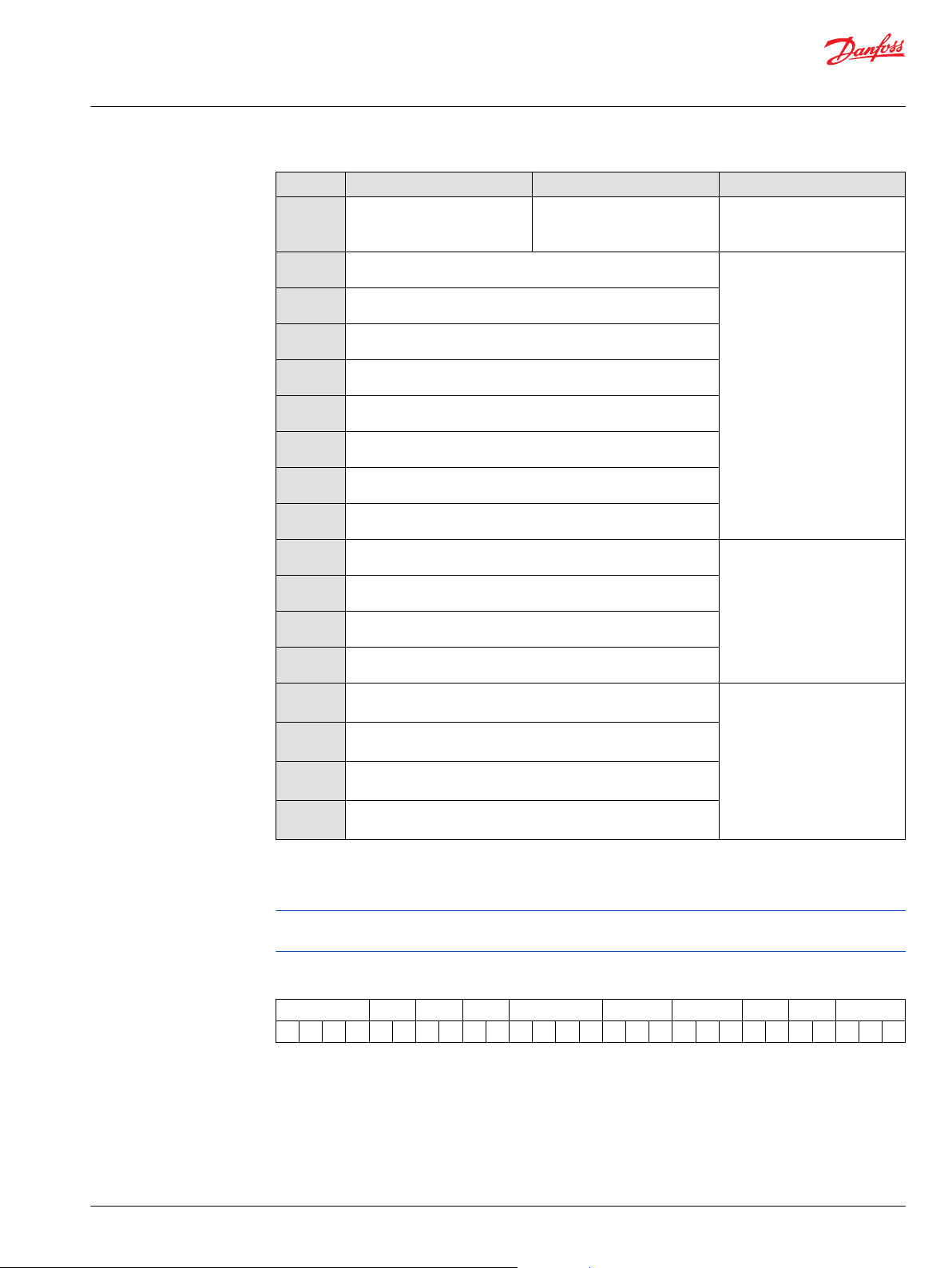
Product features
Features Description
Construction
Displacements
Continuous Pressure
Peak Pressure
Speed
Mounting
Shaft (types)
Ports
Fluid viscosity
Filtration requirement
Fluids
Operating
temperature*
Configurations
Integrated valve
options
*
Temperature and viscosity requirements must be satisfied concurrently.
Heavy duty ductile iron 3-piece construction with pressure balance load plates and
viton seals
7 to 45 cm³ [0.43 to 2.75 in3/rev]
276 bar [4000 psi] up to 32 cm³ [1.94 in3/rev]
303 bar [4400 psi] up to 32 cm³ [1.94 in3/rev]
600 to 3400 min-1 (rpm) - up to 25cm³ [1.55 in3/rev]
SAE A two bolt, SAE B two bolt, Perkins engine mount
Straight keyed, 1:8 tapered keyed, 9T, 11T, 13T and 15T splined
SAE O-ring boss, SAE split flange, beaded tube inlet (axial and radial)
*
8 mm²/sec (cSt) [36 SUS] minimum, 1600 mm²/sec (cSt) [7500 SUS] maximum
22/18/13 ISO 4406 at motor inlet
Petroleum/mineral based
-40°C [-40°F] minimum for cold start
110°C [230°F] normal operating conditions 115°C [239°F] peak intermittent
Single, tandem, triple, and quadruple multisection pumps available with common inlets.
Integrated auxiliary cover for through drive applications.
Priority flow divider with priority relief Priority steering with steering relief
Load sense priority flow divider
©
Danfoss | April 2020 BC319684134607en-000202 | 9
Page 10

Technical Information
D Series and XD Series Gear Pumps
Technical Specifications
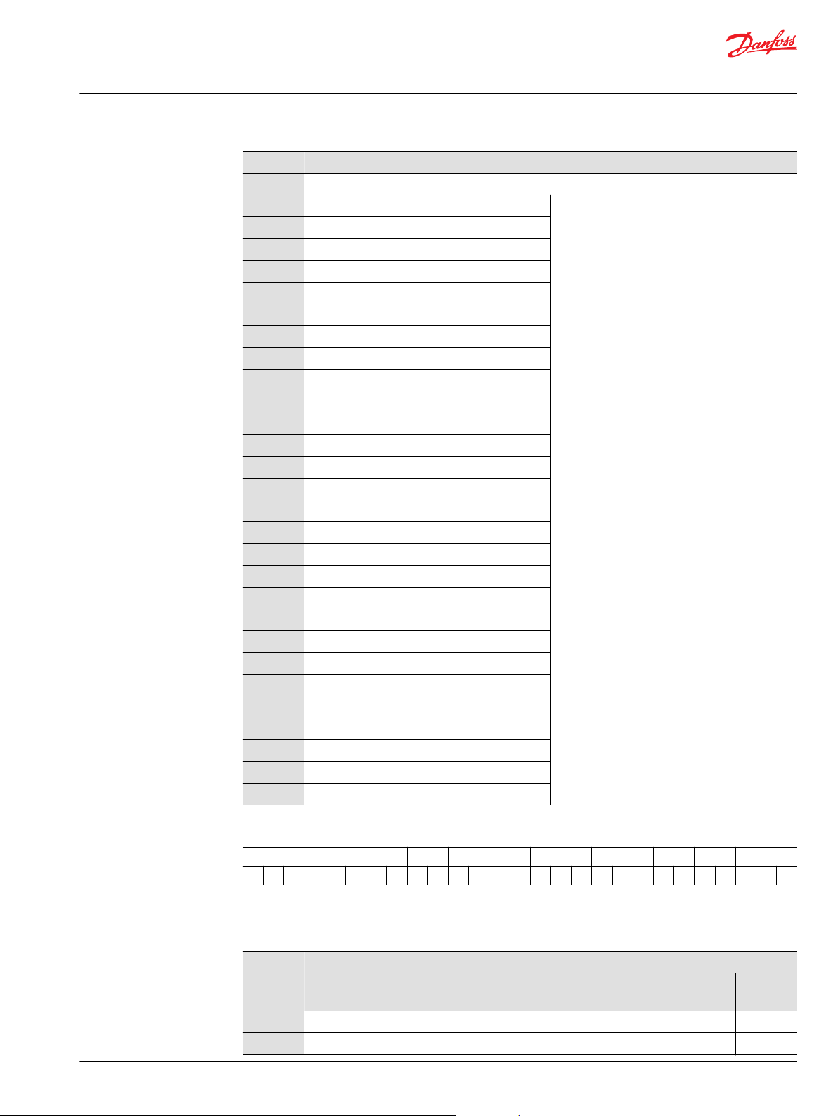
Technical specifications
Ratings Units 07 10 11 13 14 17 19 21 23 25 29 32 36 38 41 45
Displacement
Rated pressure
Peak pressure
Speed min
(rpm)
Theoretical flow at max
speed
Weight
Mass moment of inertia
*
minimum speed at maximum pressure
-1
cm3/rev 7.0 9.5 10.8 12.6 14.3 17.0 19.0 20.5 22.5 25.4 29.0 31.8 36.1 38.0 41.0 45.1
in3/rev
bar 276 276 276 276 276 276 276 276 276 276 276 276 241 228 207 190
psi
bar 303 303 303 303 303 303 303 303 303 303 303 303 265 250 228 209
psi
maximum 3400 3400 3400 3400 3400 3400 3400 3400 3400 3400 3200 3000 2750 2750 2500 2500
minimum
l/min 24.0 32.3 36.7 42.9 48.5 57.9 64.6 69.6 76.3 86.4 92.8 95.4 99.0 104.5 102.4 112.7
US gal/min
kg 7.2 7.3 7.4 7.5 7.6 7.8 7.9 7.9 8.1 8.3 8.4 8.6 8.8 9.0 9.1 9.4
lb
x10-6 kg•m² 60 71 77 85 92 104 105 119 128 141 157 170 188 197 218 228
x10-6 slug•ft²
0.43 0.58 0.66 0.77 0.87 1.04 1.16 1.25 1.37 1.55 1.77 1.94 2.20 2.32 2.50 2.75
4000 4000 4000 4000 4000 4000 4000 4000 4000 4000 4000 4000 3500 3300 3000 2750
4400 4400 4400 4400 4400 4400 4400 4400 4400 4400 4400 4400 3850 3630 3300 3025
*
1200 900 900 700 700 600 600 600 600 600 600 600 600 600 600 600
6.3 8.5 9.7 11.3 12.8 15.3 17.1 18.4 20.2 22.8 24.5 25.2 26.2 27.6 27.1 29.8
15.8 16.1 16.3 16.5 16.7 17.1 17.4 17.5 17.8 18.2 18.6 19.0 19.6 19.8 20.2 20.7
44 53 57 63 68 77 77 88 95 104 116 125 139 145 155 168
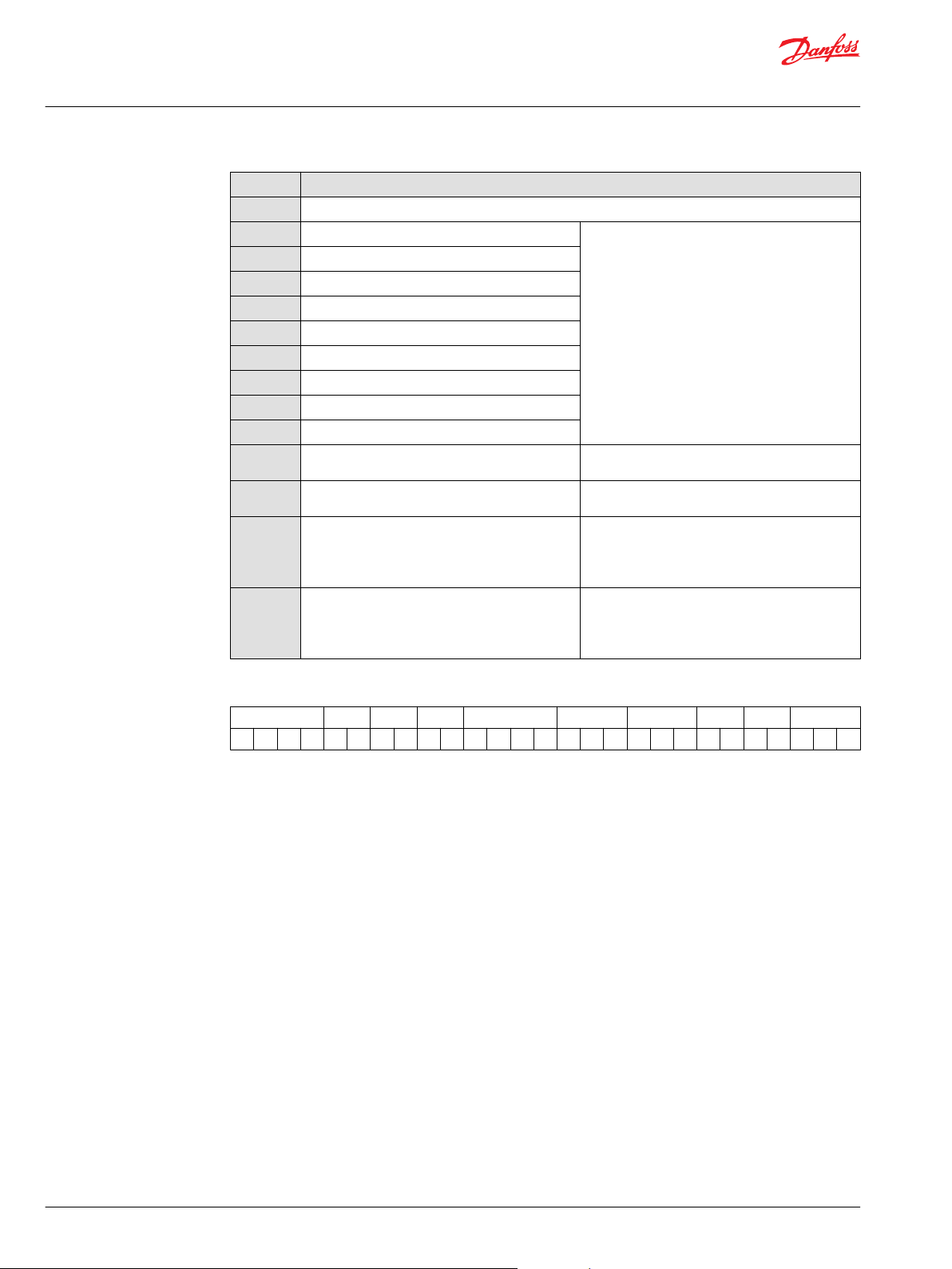
Fluid specifications
Inlet pressure
Parameter Unit Minimum Continuous Maximum
Viscosity
Temperature*
Cleanliness
Filtration efficiency, charge filtration
*
Temperature and viscosity requirements must be satisfied concurrently
*
mm2/sec (cSt)[SUS]
°C [°F] -40 [-40] 110 [230] 115 [239]
8
[52]
ISO 4406 Class 22/18/13 or better
b15-20 =75 (b10³10)
10 - 100
[59-456]
1600
[7500]
Ratings are based on operation with premium petroleum-based hydraulic fluids containing oxidation,
rust, and foam inhibitors.
Maximum continuous vacuum
Maximum intermittent vacuum
Maximum charged inlet pressure
bar atmospheric [inches mercury vacuum]
bar atmospheric [psi] 3.0 [44]
0.8 [5.9]
0.6 [11.8]
10 | © Danfoss | April 2020 BC319684134607en-000202
Page 11
Peak pressure
Rated pressure
Reaction time (100 ms max)
Time
Pressure
Technical Information
D Series and XD Series Gear Pumps
Operating Parameters
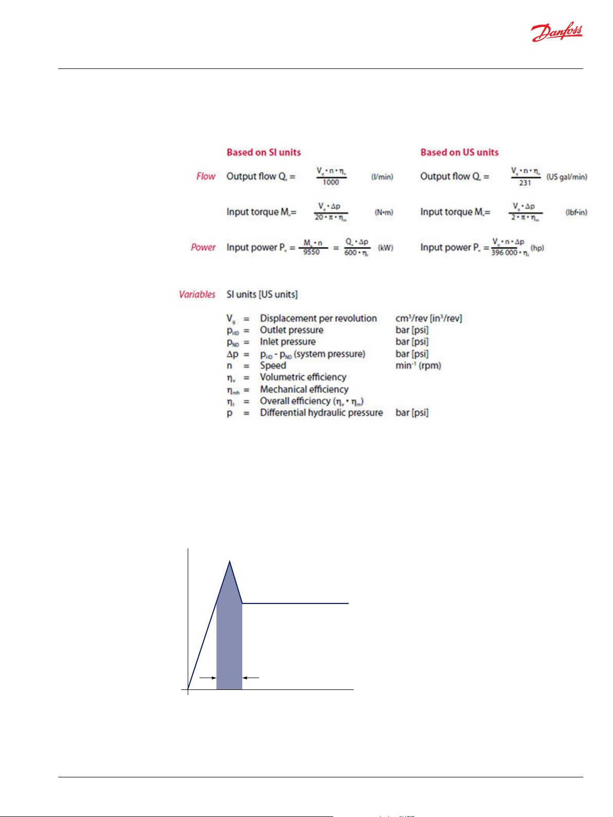
Sizing equations
Use these formulas to determine the nominal pump size for a specific application.
Pressure
Definitions of the D Series operating parameters appear below. Consult Danfoss technical support for
applications running outside of these parameters.
Peak pressure
Peak pressure is the highest intermittent pressure allowed. The relief valve overshoot (reaction time)
determines peak pressure. It is assumed to occur for less than 100 ms. The illustration to the right shows
peak pressure in relation to rated pressure and reaction time (100 ms maximum).
Rated pressure
Rated pressure is the average, regularly occurring operating outlet pressure that should yield satisfactory
product life. The maximum machine load demand determines rated pressure. For all systems, the load
should move below this pressure.
©
Danfoss | April 2020 BC319684134607en-000202 | 11
Page 12

Technical Information
D Series and XD Series Gear Pumps
Operating Parameters
System pressure
System pressure is the differential between the inlet and outlet ports. It is a dominant operating variable
affecting hydraulic unit life. High system pressure reduces expected pump life. System pressure must
remain at, or below, rated pressure during normal operation to achieve expected life.
Inlet vacuum
Inlet vacuum must be controlled in order to realize expected performance and pump life. System design
must meet inlet vacuum requirements during all modes of operation. Expect lower inlet vacuums during
cold start situations. Low vacuum condition should improve quickly as fluid warms.
Pressure rise rate
The maximum pressure rise rate is the rate of increase in system pressure as measured at the outlet port
of the pump. High pressure rise rates are commonly seen on work function applications during motor
start-up, completion of cylinder stroke, and during rapid shifting of control valves. The maximum
pressure rise rate of the D pump is 11,720 bar/sec [170,000 psi/sec]. During rapid rise rate situations, the
system pressure must not exceed the rated pressure of the pump.
Temperature and viscosity
Temperature
High temperature limits apply at the inlet port of the pump. The pump should run at or below the
maximum continuous temperature.
Minimum (cold start) temperature relates to the physical properties of component materials.
Cold oil, generally, doesn’t affect the durability of pump components. It may affect the ability of oil to
flow and transmit power. For this reason, keep the temperature at 16°C [29 °F] above the pour point of
the hydraulic fluid.
Continuous temperature is the temperature at or below the temperature which normal pump life can
be expected.
Maximum temperature is the highest temperature that is tolerable by the machine for a transient/
limited time (duty cycle 1% or less). At maximum temperature, oil viscosity must not go lower than
minimum recommended viscosity.
Viscosity
Continuous viscosity: Recommended viscosity range for maximum efficiency and pump life.
Minimum viscosity occurs only during brief occasions of maximum fluid temperature and severe duty
cycle operation. It’s the minimum acceptable viscosity to guarantee the pump life. (Duty
cycle 1% or less)
Maximum viscosity occurs only during cold start at very low temperatures. It is the upper limit of
viscosity that allows the pump to start. During this condition, limit speeds until the system warms up.
Temperature and viscosity requirements must be concurrently satisfied.
Speed
Maximum speed is the limit recommended for operation at rated pressure. It is the highest speed at
which normal life can be expected.
The lower limit of operating speed is the minimum speed.
12 | © Danfoss | April 2020 BC319684134607en-000202
Page 13
C
Technical Information
D Series and XD Series Gear Pumps
Operating Parameters
Hydraulic fluid
Ratings and data for gear pumps are based on operation with premium hydraulic fluids containing
oxidation, rust, and foam inhibitors. These fluids must possess good thermal and hydrolytic stability to
prevent wear, erosion, and corrosion of internal components.
Use only clean fluid in the pump and hydraulic circuit.
Caution
Never mix hydraulic fluids.
Filtration
Filters
Use a filter that conforms to Class 22/18/13 of ISO 4406 (or better). It may be on the pump outlet
(pressure filtration), inlet (suction filtration), or reservoir return (return-line filtration).
Selecting a filter
When selecting a filter, please consider:
•
contaminant ingression rate (determined by factors such as the number of actuators used in the
system)
•
generation of contaminants in the system
•
required fluid cleanliness
•
desired maintenance interval
•
filtration requirements of other system components
Measure filter efficiency with a Beta ratio (βX). For:
•
suction filtration, with controlled reservoir ingression, use a β
•
return or pressure filtration, use a pressure filtration with an efficiency of β10 = 75
βx ratio is a measure of filter efficiency defined by ISO 4572. It is the ratio of the number of particles
greater than a given diameter ( “X“ in microns) upstream of the filter to the number of these particles
downstream of the filter.
Fluid cleanliness level and βx ratio
Fluid cleanliness level (per ISO 4406)
βx ratio (suction filtration)
βx ratio (pressure or return filtration)
Recommended inlet screen size
The filtration requirements for each system are unique. Evaluate filtration system capacity by monitoring
and testing prototypes.
Reservoir
The reservoir provides clean fluid, dissipates heat, removes entrained air, and allows fluid volume
changes associated with fluid expansion and cylinder differential volumes. A correctly sized reservoir
accommodates maximum volume changes during all system operating modes. It promotes deaeration of
the fluid as it passes through, and accommodates a fluid dwell-time between 60 and 180 seconds,
allowing entrained air to escape.
Minimum reservoir capacity depends on the volume required to cool and hold the oil from all retracted
cylinders, allowing for expansion due to temperature changes. A fluid volume of 1 to 3 times the pump
output flow (per minute) is satisfactory. The minimum reservoir capacity is 125% of the fluid volume.
Install the suction line above the bottom of the reservoir to take advantage of gravity separation and
prevent large foreign particles from entering the line. Cover the line with a 100-125 micron screen. The
= 75 filter
35-45
Class 22/18/13 or better
β
= 75 and β10 = 2
35-45
β10 = 75
100-125 µm [0.004-0.005 in]
©
Danfoss | April 2020 BC319684134607en-000202 | 13
Page 14
Pilot cavity
Ø 0.1 [0.004]
Mating spline
Technical Information
D Series and XD Series Gear Pumps
Operating Parameters
pump should be below the lowest expected fluid level. Put the return-line below the lowest expected
fluid level to allow discharge into the reservoir for maximum dwell and efficient deaeration. A baffle (or
baffles) between the return and suction lines promotes deaeration and reduces fluid surges.
Line sizing
Choose line sizes that accommodate maximum fluid velocity to reduce system noise, pressure drops, and
overheating in order to maximize system life and performance. Line velocities shown in the following
table provide a general rule of thumb. Final selection of line sizing and fittings must comply with all
pressure ratings.
Pump life
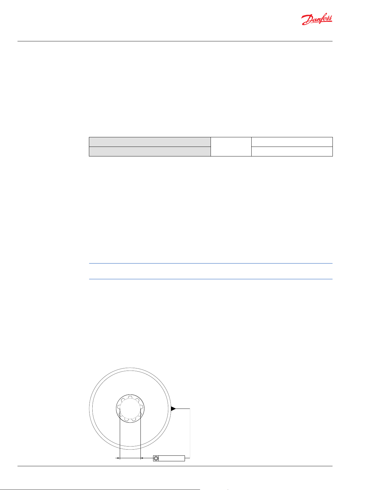
Pump shaft connection
Inlet
Outlet 6-9 [20-30]
m/sec [ft/sec]
2.4-4.3 [8-14]
Most systems use hydraulic oil containing 10% dissolved air by volume. Over-areation, or entrained air is
the result of flow line restrictions, where the dissolved air comes out of solution, or when air is allowed to
leak into the hydraulic circuit. These include inadequate pipe sizes, sharp bends, or elbow fittings,
causing reduction of flow-line cross-sectional area. This problem will not occur if these circuit
recommendations are followed, rated speed requirements are maintained, and reservoir size and
location are adequate.
Pump life is a function of speed, system pressure, and other system parameters (such as fluid quality and
cleanliness).
All Danfoss gear pumps use hydrodynamic journal bearings with an oil film between the gear/shaft and
bearing surfaces. If the oil film is sufficiently sustained through proper system maintenance and
operating within recommended limits, long life can be expected.
ß10 life expectancy number is generally associated with rolling element bearings. It does not exist for
hydrodynamic bearings.
When submitting an application for review, provide machine duty cycle data including percentage of
time at various loads and speeds. We strongly recommend a prototype testing program to verify
operating parameters and their impact on life expectancy before finalizing any system design.
Shaft options for gear pumps include tapered, splined, or parallel shafts.
Plug-in drives, with a splined shaft, can impose severe radial loads when the mating spline is rigidly
supported. Increasing spline clearance does not alleviate this condition.
Pump shaft connection
14 | © Danfoss | April 2020 BC319684134607en-000202
Page 15
C
P107 928E
3:00
12:00
9:00
6:00
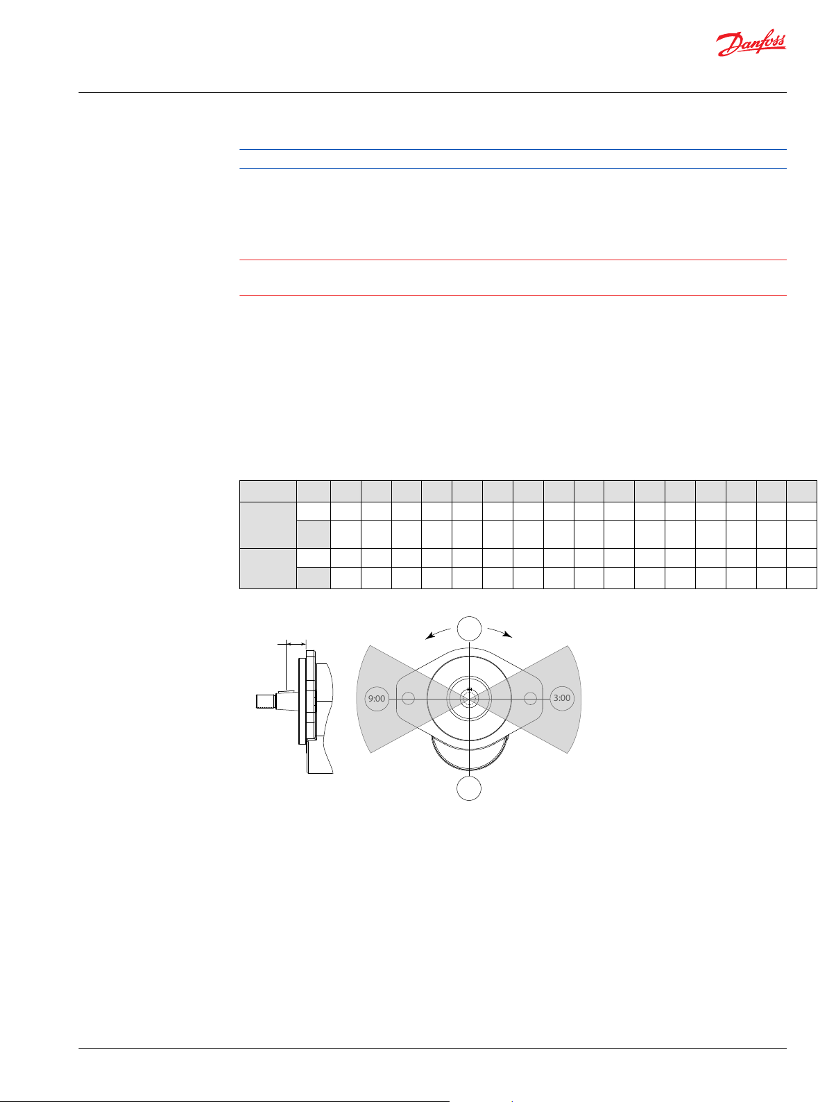
Shaft loading
• All values measured 25.4 mm [1 inch]
from the mounting flange
• For other orientations and distances,
higher radial loads at lower pressures
contact your S-D representative
25.4 mm
[1 inch]
Recommended loading position
CW Rotation
CCW Rotation
Technical Information
D Series and XD Series Gear Pumps
Operating Parameters
Lubricate all shaft couplings. Failure to do so will result in premature shaft failure.
Use plug-in drives if the concentricity between the mating spline and pilot diameter is within 0.1 mm
[0.004 in]. Lubricate the drive by flooding it with oil. A 3-piece coupling minimizes radial or thrust shaft
loads.
Caution
To avoid spline shaft damages it is recommended to use carburized and hardened steel couplings with
80-82 HRA surface hardness.
Radial and axial loading
Allowable radial shaft loads are a function of the load position, load orientation, and operating pressure.
All external shaft loads have an effect on bearing life, and may affect pump performance.
In applications where external shaft loads cannot be avoided, minimize the impact on the pump by
optimizing the orientation and magnitude of the load. Use tapered input shafts for applications with
radial shaft loads. The table below shows the preferred orientation for radial loads assuming maximum
pressure. For assistance concerning shaft loading, contact your Danfoss representative.
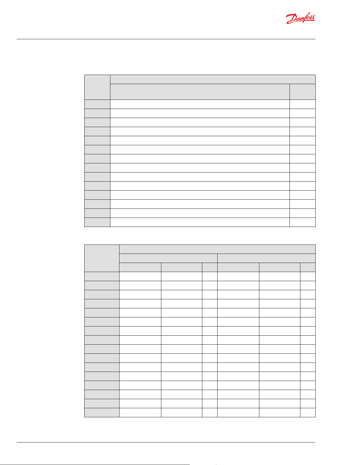
Maximum radial and axial loads
Ratings Units 7 10 11 13 14 17 19 21 23 25 29 32 36 38 41 45
Maximum
radial
load
Push/Pull
axial load
lbf 1430 1430 1430 1430 1430 1430 1360 1300 1210 1070 870 700 420 270 450 620
6361 6361 6361 6361 6361 6361 5943 5783 5382 4760 3870 3114 1868 1201 2002 2758
N
lbf 350 350 350 350 350 350 350 350 350 350 350 350 350 350 350 350
1557 1557 1557 1557 1557 1557 1557 1557 1557 1557 1557 1557 1557 1557 1557 1557
N
©
Danfoss | April 2020 BC319684134607en-000202 | 15
Page 16
Technical Information
D Series and XD Series Gear Pumps
D Series Model Code
Single pump order code
Example
A B1 B2 C D E F H J K
D E 1 R 2 1 S H A C F 0 9 A 1 5 X 1 7 2 C Z A N N N N
Code Position Description
DE1R
21
SH
AC
F09A
15X
172
CZ
AN
NNN
A D Series pump, single section, right hand rotation
B1 21 cm³ displacement
B2 13 tooth spline input shaft
C SAE A two bolt mounting flange
D Integrated priority flow divider with cartridge style priority relief, 1 5/16-12 side inlet,
3/14-16 side priority, 7/8-14 side secondary
E 15.1 l/min[4 US gal/min] priority flow setting
F 172 bar [2495 psi] priority relief setting
H Assembly screws
J Standard Nameplate
K No special features, black paint
DE1: D series cast iron gear pump, single section
A Rotation - viewed from drive shaft
A B1 B2 C D E F H J K
D E 1 ●
Code Description
L Lefthand (counterclockwise)
R Right hand (clockwise)
B1 Displacement
A B1 B2 C D E F H J K
D E 1 ● ●
Code Description
07
10
11
13
14
17
19
21
23
25
7.0 cm³/rev [0.43 in3/rev]
9.5 cm³/rev [0.58 in3/rev]
10.8cm³/rev [0.66 in3/rev]
12.6cm³/rev [0.77 in3/rev]
14.3cm³/rev [0.87 in3/rev]
17.0cm³/rev [1.04 in3/rev]
19.0cm³/rev [1.16 in3/rev]
20.5cm³/rev [1.25 in3/rev]
22.5 cm³/rev [1.37 in3/rev]
25.4 cm³/rev [1.55 in3/rev]
16 | © Danfoss | April 2020 BC319684134607en-000202
Page 17
Technical Information
D Series and XD Series Gear Pumps
D Series Model Code
Code Description
29
32
36
38
41
45
B2 Input shaft
A B1 B2 C D E F H J K
D E 1 ● ●
Code Description
*
SE
SC
SF
SH
SV
PB
PD
PZ
TA
TG
TH
TX
WT
AB
AC
AH
*
Contact factory for units with SE (9T spline) to verify torque limits
29.0 cm³/rev [1.77 in3/rev]
31.8 cm³/rev [1.94 in3/rev]
36.1 cm³/rev [2.20 in3/rev]
38.0 cm³/rev [2.32 in3/rev]
41.0 cm³/rev [2.50 in3/rev]
45.1 cm³/rev [2.75 in3/rev]
SAE 9 tooth spline, 31.8 mm [1.25 in] length
SAE 11 tooth spline, 38.1 mm [1.5 in] length
11 tooth spline, 31.8 mm [1.25 in] length (special modified length)
SAE 13 tooth spline, 41 mm [1.62 in] length
15 tooth spline, 46 mm [1.81 in] length (use with mounting flange AR or BR)
22 mm [7/8 in] diameter, 41 mm [1.62 in] length, with 1/4 key
19 mm [3/4 in] diameter, 51 mm [2 in] length, with 3/16 key
25.4 mm [1 in] diameter, 46 mm [1.81 in] length with 1/4 key
1:5taper, 25mm [1 in] dia, 58mm [2.30 in] length, 5/8 thread, M5 key with locknut and washer
1:8taper, 22mm [7/8 in] dia, 50mm [1.95 in] length, 5/8 thread with key, locknut and washer
1:8taper, 22mm [7/8 in] dia, 49mm [1.94 in] length, 9/16 thread with key, locknut and washer
1:4 taper, 22mm [7/8 in] dia, 50mm [1.98 in] length, 5/16 internal thread with key
Input shaft similar to TH option with 34 tooth helical gear for Perkins engine mount
22mm[7/8 in] diameter, 41mm [1.62] length with 1/4 key with 9T spline through drive
SAE 11 tooth spline, 38.1 mm [1.5 in] length with 9T spline through drive
SAE 13 tooth spline, 41 mm [1.62 in] length with 9T spline through drive
C Mounting flange
A B1 B2 C D E F H J K
D E 1 ● ●
Code Description
AA
AC
AL
AM
AP
AR
©
Danfoss | April 2020 BC319684134607en-000202 | 17
SAE A 2-bolt
SAE A 2-bolt, use with integral PFD/Steering Cover
SAE A 2-bolt, two shaft seals with weep hole
SAE A 2-bolt, with T seal
SAE A 2-bolt, with T seal, use with integral PFD/Steering cover
SAE A 2-bolt, use with 15 T spline input drive
Page 18
Technical Information
D Series and XD Series Gear Pumps
D Series Model Code
Code Description
AS
AT
BB
BC
BM
BP
BR
BS
BT
BW
PP
D Rear cover: Port options, integrated valves, and auxillary flange
A B1 B2 C D E F H J K
D E 1 ● ● ● ●
SAE A 2-bolt, use with integral PFD/Steering cover and 15 T input spline
SAE A 2-bolt, two shaft seals with weep hole, use with integral PFD/Steering cover
SAE B 2-bolt
SAE B 2-bolt, use with integral PFD/Steering cover
SAE B 2-bolt, with T seal
SAE B 2-bolt, with T seal, use with integral PFD/Steering cover
SAE B 2-bolt, use with 15 T spline input drive
SAE B 2-bolt, use with integral PFD/Steering cover and 15 T input spline
SAE B 2-bolt, two shaft seals with weep hole, use with integral PFD/Steering Cover
SAE B 2-bolt, two shaft seals with weep hole
Perkins 6 bolt flange with (2) seals (use with WT input shaft and clockwise rotation)
Code Inlet Outlet Description
N101
N103
N104
N125
N501
N503
N504
N252
N402
N403
N404
N407
N408
N342
N704
N708
N715
N716
N720
B103
B104*
1 1/16-12 side inlet 7/8-14 side outlet
1 5/16-12 side inlet 7/8-14 side outlet
1 5/16-12 side inlet 1 1/16-12 side outlet
1 5/8-12 side inlet 1 1/16-12 side outlet
1 1/16-12 rear inlet 7/8-14 rear outlet
1 5/16-12 rear inlet 7/8-14 rear outlet
1 5/16-12 rear inlet 1 1/16-12 rear outlet
M33x2-6H rear inlet M22x1.5-6H side outlet SAE Metric Ports – No Integrated
3/4-14 side inlet 1/2-14 side outlet
1-11 side inlet 1/2-14 side outlet
1 1/4-11 side inlet 1/2-14 side outlet
1-11 side inlet 3/4-14 side outlet
1 1/4-11 side inlet 3/4-14 side outlet
1 1/4 side split flange inlet 3/4side split flange outlet (SAE
code 61)
1 1/4 side tube inlet 7/8-14 side ORB outlet
1 1/4 side tube inlet 1 1/16-12 side ORB outlet
1 1/4 REAR tube inlet 1 1/16-12 REAR ORB outlet
1 1/2 side tube inlet 1 1/16-12 side ORB outlet
1 1/4 REAR tube inlet 7/8-14 REAR ORB outlet
*
1 5/16-12 side inlet 7/8-14 side outlet
1 5/16-12 side inlet 1 1/16-12 side outlet
SAE O-ring boss ports No
integrated valves No auxiliary
flange
Valves
British Standard Pipe Parallel
(BSPP) threads - No integrated
valves
SAEsplit flange ports No
integrated valves Noauxiliary
flange
Beaded tube inlet port, SAE Oring boss outlet port No
integrated valves
No auxiliary flange
SAE-A2-Bolt Auxiliary Flange
SAEO-ring boss ports
No integrated valves
18 | © Danfoss | April 2020 BC319684134607en-000202
Page 19
Technical Information
D Series and XD Series Gear Pumps
D Series Model Code
Code Inlet Outlet Description
R104
**
F09A
‡
F09B
F13A**
F13B‡
F21A**
F21B‡
F25A**
F25B‡
D23A*
D23B**
D24A*
D24B**
L01A**
L01B‡
L08A**
L08B‡
*
Integrated auxilliary flange requires use of input shaft option AH or AC
**
Requires use of mounting flange option AC or AP
‡
Requires use of mounting flange option BC or BP
1 5/16-12 side inlet 1 1/16-12 side outlet Integrated Relief Valve Internally
Drained
Maximum Displacement 23cc
15/16-12 side inlet, 3/4-16 side priority, 7/8-14side secondary (SAE A
flange)
1 5/8-12 rear inlet, 3/4-16 rear priority, 7/8-14 rear secondary (SAE A
flange)
1 5/8-12 rear inlet, 3/4-16 rear priority, 7/8-14 rear secondary (SAE A
flange)
1 5/8-12 rear inlet, 3/4-16 rear priority, 7/8-14 rear secondary (SAE B
flange)
15/8-12 side inlet, 3/4-16 side priority, 7/8-14 side secondary (SAE A
flange)
15/8-12 side inlet, 3/4-16 side priority, 7/8-14 side secondary (SAE B
flange)
1 5/16-12 rear inlet, 3/4-16 rear priority, 7/8-14 rear secondary (SAE A
flange)
1 5/16-12 rear inlet, 3/4-16 rear priority, 7/8-14 rear secondary (SAE B
flange)
15/16-12 side inlet, 3/4-16 side priority, nosecondary port (SAE A
flange)
15/16-12 side inlet, 3/4-16 side priority, nosecondary port (SAE B
flange)
1 5/16-12 rear inlet, 3/4-16 rear priority, no secondary port (SAE A
flange)
1 5/16-12 rear inlet, 3/4-16 rear priority, no secondary port (SAE B
flange)
1 5/16-12 side inlet, 3/4-16 side priority, 7/8-14 side secondary,
7/16-20 side LS (SAE-A flange)
1 5/16-12 side inlet, 3/4-16 side priority, 7/8-14 side secondary,
7/16-20 side LS (SAE-B flange)
1 5/16-12 rear inlet, 3/4-16 rear priority, 7/8-14 rear secondary,
7/16-20 rear LS (SAE-A flange)
1 5/16-12 rear inlet, 3/4-16 rear priority,
7/8-14 rear secondary, 7/16-20 rear LS (SAE-B flange)
Integrated Priority Flow Divider,
cartridge style relief
for settings up to: 221barand
34.3 l/min
[3200 psi and 9 US gal/min]
Integrated Steering Cover,
Priority Relief Valve
(Cartridge Style) for settings up
to: 221 bar and 34.3 l/min
[3200 psi and 9 US gal/min]
Integrated Load Sense Divider
(Dynamic), Priority Relief Valve
A variety of integrated load sense priority flow divider covers are available from Danfoss. Please contact
your technical representative to determine which hardware best suits specific application needs.
E Flow control valve setting
A B1 B2 C D E F H J K
D E 1 ● ● ●
©
Danfoss | April 2020 BC319684134607en-000202 | 19
Page 20
Technical Information
D Series and XD Series Gear Pumps
D Series Model Code
Code Description
NNN Noflow control setting, standard for units without integrated flow control valves
04X 3.8 l/min [1 US gal/min]
08X 7.6 l/min [2 US gal/min]
11X 11.4 l/min [3 US gal/min]
15X 15.1 l/min [4 US gal/min]
19X 18.9 l/min [5 US gal/min]
23X 22.7 l/min [6 US gal/min]
27X 26.5 l/min [7 US gal/min]
30X 30.3 l/min [8 US gal/min]
34X 34.3 l/min [9 US gal/min]
38A 10 bar standby
38L 10 bar standby
R1N
R2N
Maximum flow not to exceed 75 l/min, pressure
rangefrom 7-55bar
Maximum flow not to exceed 75 l/min, pressure
rangefrom 41-248bar
For integrated PFD
Steering cover with cartridge style relief valve
(Cover options F09A, F09B, F13A, F13B, F21A, F21B,
F25A or F25B)
Forintegrated load sense divider (use with L08A or
L08B rear ports)
Forintegrated load sense divider (use with L01A or
L01B side ports)
For integrated relief valve, internally drained
(without flow control)
Use with R104 cover option
23cc and under
For integrated relief valve, internally drained
(without flow control)
Use with R104 cover option
23cc and under
F Pressure control valve setting
A B1 B2 C D E F H J K
D E 1 ● ● ●
20 | © Danfoss | April 2020 BC319684134607en-000202
Page 21
Technical Information
D Series and XD Series Gear Pumps
D Series Model Code
Code Description
000 Nopressure control settings, standard for units without integrated pressure control valves
034 34 bar [500 psi]
041 41 bar [600 psi]
048 48 bar [700 psi]
055 55 bar [800 psi]
062 62 bar [900 psi]
069 69 bar [1000 psi]
076 76 bar [1100 psi]
083 83 bar [1200 psi]
090 90 bar [1300 psi]
097 97 bar [1400 psi]
103 103 bar [1500 psi]
110 110 bar [1600 psi]
117 117 bar [1700 psi]
124 124 bar [1800 psi]
131 131 bar [1900 psi]
138 138 bar [2000 psi]
145 145 bar [2100 psi]
152 152 bar [2200 psi]
159 159 bar [2300 psi]
165 165 bar [2400 psi]
172 172 bar [2500 psi]
179 179 bar [2600 psi]
186 186 bar [2700 psi]
193 193 bar [2800 psi]
200 200 bar [2900 psi]
207 207 bar [3000 psi]
214 214 bar [3100 psi]
221 221 bar [3200 psi]
For integrated priority flow divider (PFD) cover
with cartridge style relief valve
(Cover optionsF09A, F09B, F13A, F13B, F21A, F21B,
F25A, F25B)
For integrated steering cover with cartridge style
relief valve (Cover options D23A, D23B, D24A,
D24B)
For integrated load sense (LS) cover with cartridge
relief valve (Cover options L01A, L01B, L08A, L08B)
H Assembly Screws - depending on rear cover
A B1 B2 C D E F H J K
D E 1 ● ●
(Choose Table 1 or Table 2)
Table 1. Single pumps without auxiliary cover or integrated valves
Displacem
ent
(Module
B)
07 AF AJ
10 AG AJ
©
Danfoss | April 2020 BC319684134607en-000202 | 21
N101, N103, N104, N501, N503, N504, N704, N708 N125
Rear Cover - Controls & Ports (Module D)
Page 22
Technical Information
D Series and XD Series Gear Pumps
D Series Model Code
Table 1. Single pumps without auxiliary cover or integrated valves (continued)
Displacem
ent
(Module
B)
11 AG AJ
13 AG AJ
14 AG AK
17 AH AK
19 AH AK
21 AH AL
23 AJ AL
25 AJ AL
29 AK AM
32 AK AM
36 AL AN
38 AL AN
41 AM AP
45 AM AR
Rear Cover - Controls & Ports (Module D)
N101, N103, N104, N501, N503, N504, N704, N708 N125
Table 2. Single pumps with auxiliary cover or integrated valves, dependent on rotation
Rear Cover - Controls & Ports (Module D)
Displacement
(Module B)
F09A F13A, F21A F09B F13B, F21B B104 F09A F13A, F21A F09B F13B, F21B B104
07 CV DG AG EM DG AG
10 CV DG AH EM DG AH
11 CV DG AH EM DG AH
13 CX DJ AH EP DJ AH
14 CX DJ AH EP DJ AH
17 CY DK AJ ER DK AJ
19 CZ DL AJ ES DL AJ
21 CZ DL AJ ES DL AJ
23 CZ DM AJ ES DM AJ
25 DA DN AK ET DN AK
29 DB DP AK EY DP AK
32 DC DR AL EU DR AL
36 DD DS AM EV DS AM
38 DE DT AM EW DT AM
41 DE DT AM EW DT AM
45 DF DU AN EX DU AN
Right Hand (CW) Rotation Left Hand (CCW) Rotation
22 | © Danfoss | April 2020 BC319684134607en-000202
Page 23

Technical Information
D Series and XD Series Gear Pumps
D Series Model Code
J Nameplates
A B1 B2 C D E F H J K
D E 1 ● ●
Code Description
AN Standard nameplate
K Special feature
A B1 B2 C D E F H J K
D E 1 ● ● ●
Code Description
NNN No special features, standard black paint
Two section (tandem) pump order code
Example
The order code below provides an example of a single section pump with integrated priority flow divider
A B1 B2 C R S D E F H J K
D E 2 R 2 3 S H B B 1 0 4 1 3 N 1 1 3 N N N O O O A V A N N N N
Code Position Description
DE2R
23
SH
BB
104
13
N113
NNN
000
AV
AN
NNN
A D Series pump with two pumping sections, right hand rotation
B1 23 cm³ displacement on first section
B2 13 tooth spline input shaft
C SAE B two bolt mounting flange
R 1 5/16-12 side inlet, 1 1/16 side outlet on first section
S 13 cm³ displacement on second section
D No inlet and 7/8-14 side outlet on second section
E No flow control setting
F No pressure control setting
H Assembly screws
J Standard Nameplate
K No special features, black paint
A Rotation - viewed from drive shaft
A B1 B2 C R S D E F H J K
D E 2 ●
Code Description
L
R
©
Danfoss | April 2020 BC319684134607en-000202 | 23
Lefthand (counterclockwise)
Right hand (clockwise)
Page 24
Technical Information
D Series and XD Series Gear Pumps
D Series Model Code
B1 Displacement
A B1 B2 C R S D E F H J K
D E 2 ● ●
Code Description
07
10
11
13
14
17
19
21
23
25
29
32
36
38
41
45
7.0 cm³/rev [0.43 in3/rev]
9.5 cm³/rev [0.58 in3/rev]
10.8cm³/rev [0.66 in3/rev]
12.6cm³/rev [0.77 in3/rev]
14.3cm³/rev [0.87 in3/rev]
17.0cm³/rev [1.04 in3/rev]
19.0cm³/rev [1.16 in3/rev]
20.5cm³/rev [1.25 in3/rev]
22.5cm³/rev [1.37 in3/rev]
25.4cm³/rev [1.55 in3/rev]
29.0cm³/rev [1.77 in3/rev]
31.8cm³/rev [1.94 in3/rev]
36.1cm³/rev [2.20 in3/rev]
38.0cm³/rev [2.32 in3/rev]
41.0cm³/rev [2.50 in3/rev]
45.1cm³/rev [2.75 in3/rev]
B2 Input shaft
A B1 B2 C R S D E F H J K
D E 2 ● ●
Code Description
*
SE
SC
SF
SH
SV
PB
PD
PZ
TA
TG
TH
WT
*
Contact factory for units with SE (9T spline) to verify torque limits
SAE 9 tooth spline, 31.8 mm [1.25 in] length
SAE 11 tooth spline, 38.1 mm [1.50 in] length
11 tooth spline, 31.8 mm [1.25 in] length (special modified length)
SAE 13 tooth spline, 41 mm [1.62 in] length
15 tooth spline, 46 mm [1.81 in] length (requires mounting flange AR or BR)
22 mm [7/8 in] diameter x 41 mm [1.62 in] length, with 1/4 inch key
19 mm [3/4 in] diameter x 51 mm [2.0 in] length, with 3/16 inch key
25.4 mm [1 inch] diameter x 46 mm [1.81 in] length, with 1/4 inch key
1:5taper, 25mm [1 in] dia, 58mm [2.30 in] length, 5/8 thread, M5 key with locknut and washer
1:8taper, 22mm [7/8 in] dia, 50mm [1.95 in] length, 5/8 thread with key, locknut and washer
1:8taper, 22mm [7/8 in] dia, 49mm [1.94 in] length, 9/16 thread with key, locknut and washer
Input shaft similar to TH option with 34 tooth helical gear for Perkins engine mount
24 | © Danfoss | April 2020 BC319684134607en-000202
Page 25
Technical Information
D Series and XD Series Gear Pumps
D Series Model Code
C Mounting flange
A B1 B2 C R S D E F H J K
D E 2 ● ●
Code Description
AA
AC
AM
AP
AR
AS
AL
AT
BB
BC
BM
BP
BR
BS
BT
BW
PP
SAE A 2-bolt
SAE A 2-bolt, use with integral PFD/Steering Cover
SAE A 2-bolt, with T seal
SAE A 2-bolt, with T seal, use with integral PFD/Steering cover
SAE A 2-bolt, use with 15 T spline input drive
SAE A 2-bolt, use with integral PFD/Steering cover and 15 T input spline
SAE A 2-bolt, two shaft seals with weep hole
SAE A 2-bolt, two shaft seals with weep hole, use with integral PFD/Steering cover
SAE B 2-bolt
SAE B 2-bolt, use with integral PFD/Steering cover
SAE B 2-bolt, with T seal
SAE B 2-bolt, with T seal, use with integral PFD/Steering cover
SAE B 2-bolt, use with 15 T spline input drive
SAE B 2-bolt, use with integral PFD/Steering cover and 15 T input spline
SAE B 2-bolt, two shaft seals with weep hole, use with integral PFD/Steering Cover
SAE B 2-bolt, two shaft seals with weep hole
Perkins 6 bolt flange with (2) seals (use with WT input shaft and clockwise rotation)
R Ports - First section
A B1 B2 C R S D E F H J K
D E 2 ● ● ●
Code Description
101 1 1/16-12 side inlet, 7/8-14 side outlet
103 1 5/16-12 side inlet, 7/8-14 side outlet
104 1 5/16-12 side inlet, 1 1/16-12 side outlet
113 No inlet, 7/8-14 side outlet
125 1 5/8-12 side inlet, 1 1/16-12 side outlet
126 No inlet, 1 1/16-12 side outlet
341 Noinlet, 3/4 side split flange outlet (SAE Code 61)
342
11/4 side split flange inlet, 3/4 side split flange outlet(SAE Code
61)
SAE O-ring boss ports No integrated
SAESplit Flange Ports - No
integratedvalves
valves
©
Danfoss | April 2020 BC319684134607en-000202 | 25
Page 26
Technical Information
D Series and XD Series Gear Pumps
D Series Model Code
Code Description
401 No inlet, 1/2-14 side outlet
402 3/4-14 side inlet, 1/2-14 side outlet
403 1-11 side inlet, 1/2-14 side outlet
404 1 1/4-11 side inlet, 1/2-14 side outlet
405 No inlet, 3/4-14 side outlet
407 1-11 side inlet, 3/4-14 side outlet
408 1 1/4-11 side inlet, 3/4-14 side outlet
704 1 1/4 side tube inlet, 7/8-14 side ORB outlet
708 11/4 side tube inlet, 1 1/16-12 side ORB outlet
716 11/2 side tube inlet, 1 1/16-12 side ORB outlet
717 1 1/2 side tube inlet, 7/8-14 side ORB outlet
S Displacement - Second section
A B1 B2 C R S D E F H J K
D E 2 ● ●
British Standard Pipe Parallel (BSPP)
threads - No integrated valves
Beaded tube inlet port
SAE O-ring boss outlet port No
integrated valves
Code Description
07
10
11
13
14
17
19
21
23
25
29
32
36
38
41
45
7.0 cm³/rev [0.43 in3/rev]
9.5 cm³/rev [0.58 in3/rev]
10.8cm³/rev [0.66 in3/rev]
12.6cm³/rev [0.77 in3/rev]
14.3cm³/rev [0.87 in3/rev]
17.0cm³/rev [1.04 in3/rev]
19.0cm³/rev [1.16 in3/rev]
20.5 cm³/rev [1.25 in3/rev]
22.5 cm³/rev [1.37 in3/rev]
25.4 cm³/rev [1.55 in3/rev]
29.0 cm³/rev [1.77 in3/rev]
31.8 cm³/rev [1.94 in3/rev]
36.1 cm³/rev [2.20 in3/rev]
38.0 cm³/rev [2.32 in3/rev]
41.0 cm³/rev [2.50 in3/rev]
45.1 cm³/rev [2.75 in3/rev]
D Rear cover: Port options, integrated valves and auxillary flange
A B1 B2 C R S D E F H J K
D E 2 ● ● ● ●
26 | © Danfoss | April 2020 BC319684134607en-000202
Page 27

Technical Information
D Series and XD Series Gear Pumps
D Series Model Code
Code Inlet Outlet Description
N101
N103
N104
N113
N125
N126
N501
N503
N504
N401
N402
N403
N404
N407
N408
N341
N342
N704
N708
N715
N716
N720
*
B103
B104*
R104
N252
*
Integrated auxilliary flange requires use of input shaft option AH or AC
1 1/16-12 side inlet 7/8-14 side outlet
1 5/16-12 side inlet 7/8-14 side outlet
1 5/16-12 side inlet 1 1/16-12 side outlet
No inlet 7/8-14 side outlet
1 5/8-12 side inlet 1 1/16-12 side outlet
No inlet 1 1/16-12 side outlet
1 1/16-12 rear inlet 7/8-14 rear outlet
1 5/16-12 rear inlet 7/8-14 rear outlet
1 5/16-12 rear inlet 1 1/16-12 rear outlet
No inlet 1/2-14 side oultet
3/4-14 side inlet 1/2-14 side outlet
1-11 side inlet 1/2-14 side outlet
1 1/4-11 side inlet 1/2-14 side outlet
1-11 side inlet 3/4-14 side outlet
1 1/4-11 side inlet 3/4-14 side outlet
No inlet 3/4side split flange outlet (SAE
code 61)
1 1/4 side split flange inlet 3/4side split flange outlet (SAE
code 61)
1 1/4 side tube inlet 7/8-14 side ORB outlet
1 1/4 side tube inlet 1 1/16-12 side ORB outlet
1 1/4 REAR tube inlet 1 1/16-12 REAR ORB outlet
1 1/2 side tube inlet 1 1/16-12 side ORB outlet
1 1/4 REAR tube inlet 7/8-14 REAR ORB outlet
1 5/16-12 side inlet 7/8-14 side outlet, SAE-A2-Bolt Auxiliary Flange
1 5/16-12 side inlet 1 1/16-12 side outlet Integrated Relief Valve Internally
1 5/16-12 side inlet 1 1/16-12 side outlet
M33x2-6H rear inlet M22x1.5-6H side outlet SAEMetric Ports – No Integrated
SAE O-ring boss ports No
integrated valves No auxiliary
flange
British Standard Pipe Parallel
(BSPP) threads - No integrated
valves
SAEsplit flange ports No
integrated valves Noauxiliary
flange
Beaded tube inlet port, SAE Oring boss outlet port No
integrated valves
No auxiliary flange
SAEO-ring boss ports
No integrated valves
Drained
Maximum Displacement 23cc
Valves
©
Danfoss | April 2020 BC319684134607en-000202 | 27
Page 28

Technical Information
D Series and XD Series Gear Pumps
D Series Model Code
Code Inlet/Outlet Description
**
F09A
‡
F09B
F13A**
F13B‡
F21A**
F21B‡
F25A**
F25B‡
*
D23A
D23B**
D24A*
D24B**
L01A**
L01B***
L08A**
L08B***
**
Requires use of mounting flange option AC or AP
‡
Requires use of mounting flange option BC or BP
*
Integrated auxilliary flange requires use of input shaft option AH or AC
15/16-12 side inlet, 3/4-16 side priority, 7/8-14side
secondary (SAE A flange)
15/16-12 side inlet, 3/4-16 side priority, 7/8-14side
secondary (SAE B flange)
1 5/8-12 rear inlet, 3/4-16 rear priority, 7/8-14 rear
secondary (SAE A flange)
1 5/8-12 rear inlet, 3/4-16 rear priority, 7/8-14 rear
secondary (SAE B flange)
15/8-12 side inlet, 3/4-16 side priority, 7/8-14 side
secondary (SAE A flange)
15/8-12 side inlet, 3/4-16 side priority, 7/8-14 side
secondary (SAE B flange)
1 5/16-12 rear inlet, 3/4-16 rear priority, 7/8-14 rear
secondary (SAE A flange)
1 5/16-12 rear inlet, 3/4-16 rear priority, 7/8-14 rear
secondary (SAE B flange)
15/16-12 side inlet, 3/4-16 side priority,
nosecondary port (SAE A flange)
15/16-12 side inlet, 3/4-16 side priority,
nosecondary port (SAE B flange)
1 5/16-12 rear inlet, 3/4-16 rear priority, no
secondary port (SAE A flange)
1 5/16-12 rear inlet, 3/4-16 rear priority, no
secondary port (SAE B flange)
1 5/16-12 side inlet, 3/4-16 side priority,
7/8-14 side secondary, 7/16-20 side LS (SAE-A
flange)
1 5/16-12 side inlet, 3/4-16 side priority,
7/8-14side secondary, 7/16-20 side LS (SAE-B
flange)
1 5/16-12 rear inlet, 3/4-16 rear priority,
7/8-14 rear secondary, 7/16-20 rear LS (SAE-A
flange)
1 5/16-12 rear inlet, 3/4-16 rear priority,
7/8-14 rear secondary, 7/16-20 rear LS (SAE-B
flange)
Integrated Priority Flow Divider, cartridge style
relief
for settings up to: 221barand 34.3 l/min
[3200 psi and 9 US gal/min]
Integrated Steering Cover,
Priority Relief Valve
(CartridgeStyle) for settings up to: 221 bar and
34.3 l/min
[3200 psi and 9 US gal/min]
Integrated Load Sense Divider (Dynamic), Priority
Relief Valve
A variety of integrated valve options including PFD, Steering Covers, and Load sense priority flow dividers
covers are available with D Series multiple pumps. Please contact your technical representative to
determine which hardware best suits specific application needs.
E Flow control valve
A B1 B2 C R S D E F H J K
D E 2 ● ● ●
28 | © Danfoss | April 2020 BC319684134607en-000202
Page 29

Technical Information
D Series and XD Series Gear Pumps
D Series Model Code
Code Description
NNN Noflow control setting, standard for units without integrated flow control valves
04X 3.8 l/min [1 US gal/min]
08X 7.6 l/min [2 US gal/min]
11X 11.4 l/min [3 US gal/min]
15X 15.1 l/min [4 US gal/min]
19X 18.9 l/min [5 US gal/min]
23X 22.7 l/min [6 US gal/min]
27X 26.5 l/min [7 US gal/min]
30X 30.3 l/min [8 US gal/min]
34X 34.3 l/min [9 US gal/min]
38A 10 bar standby
38L 10 bar standby
R1N
R2N
Maximum flow not to exceed 75 l/min, pressure
rangefrom 7-55bar
Maximum flow not to exceed 75 l/min, pressure
rangefrom 41-248bar
For integrated PFD
Steering cover with cartridge style relief valve
(Cover options F09A, F09B, F13A, F13B, F21A, F21B,
F25A or F25B)
Forintegrated load sense divider (use with L08A or
L08B rear ports)
Forintegrated load sense divider (use with L01A or
L01B side ports)
For integrated relief valve, internally drained
(without flow control)
Use with R104 cover option
23cc and under
For integrated relief valve, internally drained
(without flow control)
Use with R104 cover option
23cc and under
F Pressure control valve
A B1 B2 C R S D E F H J K
D E 2 ● ● ●
©
Danfoss | April 2020 BC319684134607en-000202 | 29
Page 30

Technical Information
D Series and XD Series Gear Pumps
D Series Model Code
Code Description
000 Nopressure control settings
034 34 bar [500 psi]
041 41 bar [600 psi]
048 48 bar [700 psi]
055 55 bar [800 psi]
062 62 bar [900 psi]
069 69 bar [1000 psi]
076 76 bar [1100 psi]
083 83 bar [1200 psi]
090 90 bar [1300 psi]
097 97 bar [1400 psi]
103 103 bar [1500 psi]
110 110 bar [1600 psi]
117 117 bar [1700 psi]
124 124 bar [1800 psi]
131 131 bar [1900 psi]
138 138 bar [2000 psi]
145 145 bar [2100 psi]
152 152 bar [2200 psi]
159 159 bar [2300 psi]
165 165 bar [2400 psi]
172 172 bar [2500 psi]
179 179 bar [2600 psi]
186 186 bar [2700 psi]
193 193 bar [2800 psi]
200 200 bar [2900 psi]
207 207 bar [3000 psi]
214 214 bar [3100 psi]
221 221 bar [3200 psi]
For integrated priority flow divider (PFD) cover
with cartridge style relief valve
(Cover optionsF09A, F09B, F13A, F13B, F21A, F21B,
F25A, F25B)
For integrated steering cover with cartridge style
relief valve (Cover options D23A, D23B, D24A,
D24B)
For integrated load sense (LS) cover with cartridge
relief valve (Cover options L01A, L01B, L08A, L08B)
H Assembly screws
A B1 B2 C R S D E F H J K
D E 2 ● ●
1. Step 1 - Select the table corresponding to the port codes of the front and rear pump
2. Step 2 - Select the row corresponding to the displacement of the front pump
3. Step 3 - Select the column corresponding to the displacement of the rear pump
4. Step 4 - Select the 2 letter code where the two displacements meet
Example from Table 1: AW = 21+19 tandem
The following tables are only applicable to port codes shown. For all other port code options (including
PFD, LS and auxiliary cover), please consult factory.
30 | © Danfoss | April 2020 BC319684134607en-000202
Page 31

Technical Information
D Series and XD Series Gear Pumps
D Series Model Code
Table
number
1
2
3
4
Table 1
Displacement
front pump
(Module B)
07
10
13
14
17
19
21
23
25
29
32
36
38
41
45
Front pump port code Module R Rear pump port code Module D
101, 103, 104, 113, 126,
704 or 708
125, 716, 717
101, 103, 104, 113, 126,
704 or 708
125, 716, 717 N125
Frontpump port code, Module: R = 101, 103, 104, 113, 126, 704, or 708 Rearpump port code,
Module: D = N101, N103,
N104, N113, N126, N501, N503, N504, N704, or N708
Displacement rear pump, Module: S
07 10 13 14 17 19 21 23 25 29 32 36 38 41 45
AS AS AS AT AT AT AU AU AU AV AV AW AW AX AY
AS AS AT AT AU AU AU AU AV AV AW AX AX AX AY
AS AT AT AU AU AU AV AV AV AW AW AX AX AY AY
AT AT AU AU AU AV AV AV AW AW AX AX AY AY AZ
AT AU AU AU AV AV AV AW AW AX AX AY AY AY AZ
AT AU AU AV AV AV AW AW AW AX AX AY AZ AZ AZ
AU AU AV AV AV AW AW AW AX AX AY AY AZ AZ BA
AU AU AV AV AW AW AW AW AX AX AY AZ AZ AZ BA
AU AV AV AW AW AW AX AX AX AY AZ AZ AZ BA BA
AV AV AW AW AX AX AX AX AY AY AZ AZ BA BA BB
AV AW AW AX AX AX AY AY AY AZ AZ BA BA BB BB
AW AX AX AX AY AY AY AY AZ AZ BA BA BB BB BC
AW AX AX AY AY AY AZ AZ AZ BA BA BB BB BC BC
AX AX AY AY AY AZ AZ AZ BA BA BB BB BC BC BD
AY AY AY AZ AZ AZ BA BA BA BB BB BC BC BD BE
N101, N103, N104, N113, N126,
N501, N503, N504, N704, or N708
N101, N103, N104, N113, N126,
N501, N503, N504, N704, or N708
N125
Table 2
Displacement
front pump
(Module B)
07
10
13
14
17
19
21
23
25
©
Danfoss | April 2020 BC319684134607en-000202 | 31
Frontpump port code, Module: R = 125, 716, 717 Rearpump port code, Module: D = N101,
N103, N104,N113,N126, N501, N503, N504, N704, or N708
Displacement rear pump, Module: S
07 10 13 14 17 19 21 23 25 29 32 36 38 41 45
AT AT AU AU AV AV AV AV AW AW AX AY AY AY AZ
AT AU AU AV AV AV AV AW AW AX AX AY AY AZ AZ
AU AU AV AV AV AW AW AW AX AX AY AY AZ AZ BA
AU AV AV AV AW AW AW AX AX AY AY AZ AZ AZ BA
AV AV AV AW AW AW AX AX AX AY AY AZ AZ BA BB
AV AV AW AW AW AX AX AX AY AY AZ AZ BA BA BB
AV AV AW AW AX AX AX AY AY AZ AZ BA BA BA BB
AV AW AW AX AX AX AY AY AY AZ AZ BA BA BB BB
AW AW AX AX AX AY AY AY AZ AZ BA BA BB BB BC
Page 32

Technical Information
D Series and XD Series Gear Pumps
D Series Model Code
Table 2
Displacement
front pump
(Module B)
29
32
36
38
41
45
Table 3 Frontpump port code, Module: R = 101, 103, 104, 113, 126, 704, or 708 Rearpump port code,
Displacement
front pump
(Module B)
07
10
13
14
17
19
21
23
25
29
32
36
38
41
45
Frontpump port code, Module: R = 125, 716, 717 Rearpump port code, Module: D = N101,
N103, N104,N113,N126, N501, N503, N504, N704, or N708
Displacement rear pump, Module: S
07 10 13 14 17 19 21 23 25 29 32 36 38 41 45
AW AX AX AY AY AY AY AZ AZ BA BA BB BB BC BC
AX AX AY AY AY AZ AZ AZ BA BA BB BB BC BC BD
AY AY AY AZ AZ AZ AZ BA BA BB BB BC BC BD BE
AY AY AZ AZ AZ BA BA BA BB BB BC BC BD BD BE
AY AZ AZ AZ BA BA BA BB BB BC BC BD BD BE BE
AZ AZ BA BA BB BB BB BB BC BC BD BE BE BE BF
Module: D = N125
Displacement rear pump, Module: S
07 10 13 14 17 19 21 23 25 29 32 36 38 41 45
AU AU AV AV AW AW AW AW AX AX AY AZ AZ AZ BA
AU AV AV AV AW AW AW AX AX AY AY AZ AZ AZ BA
AV AV AW AW AW AX AX AX AY AY AZ AZ BA BA BB
AV AV AW AW AX AX AX AY AY AZ AZ BA BA BA BB
AW AW AW AX AX AX AY AY AY AZ AZ BA BA BA BC
AW AW AX AX AX AY AY AY AZ AZ BA BA BB BB BC
AW AW AX AX AY AY AY AY AZ BA BA BB BB BB BC
AW AX AX AY AY AY AY AZ AZ BA BA BB BB BB BC
AX AX AY AY AY AZ AZ AZ BA BA BB BB BC BC BD
AX AY AY AZ AZ AZ BA BA BA BB BB BC BC BC BD
AY AY AZ AZ AZ BA BA BA BB BB BC BC BD BD BE
AZ AZ AZ BA BA BA BB BB BB BC BC BD BD BD BF
AZ AZ BA BA BA BA BB BB BC BC BD BD BE BE BF
AZ BA BA BA BB BB BB BC BC BD BD BE BE BE BF
BA BA BB BB BC BC BC BC BD BD BE BF BF BF BG
Table 4 Front pump port code, Module: R = 125, 716, 717 Rear pump port code, Module: D = N125
Displacement
front pump
(Module B)
07
10
13
14
17
19
21
23
Displacement rear pump, Module: S
07 10 13 14 17 19 21 23 25 29 32 36 38 41 45
AV AW AW AW AX AX AX AY AY AZ AZ BA BA BB BB
AW AW AX AX AX AY AY AY AZ AZ BA BA BB BB BC
AW AX AX AX AY AY AY AZ AZ BA BA BB BB BC BC
AX AX AX AY AY AY AZ AZ AZ BA BA BB BB BC BC
AX AX AY AY AY AZ AZ AZ BA BA BB BB BC BC BD
AX AY AY AY AZ AZ AZ BA BA BB BB BC BC BD BD
AY AY AY AZ AZ AZ BA BA BA BB BB BC BC BD BD
AY AY AZ AZ AZ BA BA BA BB BB BC BC BD BD BE
32 | © Danfoss | April 2020 BC319684134607en-000202
Page 33

Technical Information
D Series and XD Series Gear Pumps
D Series Model Code
Table 4 Front pump port code, Module: R = 125, 716, 717 Rear pump port code, Module: D = N125
Displacement
front pump
(Module B)
25
29
32
36
38
41
45
J Nameplate
A B1 B2 C R S D E F H J K
D E 2 ● ●
Displacement rear pump, Module: S
07 10 13 14 17 19 21 23 25 29 32 36 38 41 45
AY AZ AZ AZ BA BA BA BB BB BC BC BD BD BE BE
AZ AZ BA BA BA BA BB BB BC BC BD BD BE BE BF
AZ BA BA BA BB BB BB BC BC BD BD BE BE BF BF
BA BA BB BB BB BB BC BC BD BD BE BE BF BF BG
BA BB BB BB BC BC BC BD BD BE BE BF BF BG BG
BB BB BC BC BC BC BC BD BE BE BF BF BG BG BH
BB BC BC BC BD BD BD BE BE BF BF BG BG BH BH
Code Description
AN
K Special features
A B1 B2 C R S D E F H J K
D E 2 ● ● ●
Code Description
NNN
Three section (triple) pump order code
Example
The order code below provides an example of a three section (triple) pump with single inlet.
A B1 B2 C L M R S D E F H J K
D E 3 R 2 5 S H B B 7 1 6 2 5 1 2 6 2 5 N 1 2 6 N N N 0 0 0 B M A N N N N
Code Position
DE3R
25
SH
BB
716
25
126
25
N126
Standard nameplate
No special features, standard black paint
A D Series pump with three pumping sections, right hand rotation
B1 25 cm³ displacement on first section
B2 13 tooth spline input shaft
C SAE B two bolt mounting flange
L 11/2 inch beaded tube inlet, 1 1/16-12 side ORB outlet on first section
M 25 cm³ displacement on second section
R No inlet and 1 1/16-12 side outlet on second section
S 25 cm³ displacement on third section
D No inlet and 1 1/16-12 side outlet on third section
©
Danfoss | April 2020 BC319684134607en-000202 | 33
Page 34

Technical Information
D Series and XD Series Gear Pumps
D Series Model Code
Code Position
NNN
000
BM
AN
NNN
A Rotation - viewed from drive shaft
A B1 B2 C L M R S D E F H J K
D E 3 ●
Code Description
L
R
B1 Displacement - First section
A B1 B2 C L M R S D E F H J K
D E 3 ● ●
E No flow control setting
F No pressure control setting
G Assembly screws
H Standard Nameplate
J No special features, black paint
Lefthand (counterclockwise)
Right hand (clockwise)
Code Description
07
10
11
13
14
17
19
21
23
25
29
32
36
38
41
45
7.0 cm³/rev [0.43 in3/rev]
9.5 cm³/rev [0.58 in3/rev]
10.8 cm³/rev [0.66 in3/rev]
12.6 cm³/rev [0.77 in3/rev]
14.3 cm³/rev [0.87 in3/rev]
17.0 cm³/rev [1.04 in3/rev]
19.0 cm³/rev [1.16 in3/rev]
20.5 cm³/rev [1.25 in3/rev]
22.5 cm³/rev [1.37 in3/rev]
25.4 cm³/rev [1.55 in3/rev]
29.0 cm³/rev [1.77 in3/rev]
31.8 cm³/rev [1.94 in3/rev]
36.1 cm³/rev [2.20 in3/rev]
38.0 cm³/rev [2.32 in3/rev]
41.0 cm³/rev [2.50 in3/rev]
45.1 cm³/rev [2.75 in3/rev]
B2 Input shaft
A B1 B2 C L M R S D E F H J K
D E 3 ● ●
34 | © Danfoss | April 2020 BC319684134607en-000202
Page 35

Technical Information
D Series and XD Series Gear Pumps
D Series Model Code
Code Description
*
SE
SC
SF
SH
SV
PB
PD
PZ
TA
TG
TH
WT
*
Contact factory for units with SE (9T spline) to verify torque limits
SAE 9 tooth spline, 31.8 mm [1.25 in] length
SAE 11 tooth spline, 38.1 mm [1.50 in] length
11 tooth spline, 31.8 mm [1.25 in] length (special modified length)
SAE 13 tooth spline, 41 mm [1.62 in] length
15 tooth spline, 46 mm [1.81 in] length (requires mounting flange AR or BR)
22 mm [7/8 in] diameter x 41 mm [1.62 in] length, with 1/4 inch key
19 mm [3/4 in] diameter x 51 mm [2.0 in] length, with 3/16 inch key
25.4 mm [1 inch] diameter x 46 mm [1.81 in] length, with 1/4 inch key
1:5taper, 25mm [1 in] dia, 58mm [2.30 in] length, 5/8 thread, M5 key with locknut and washer
1:8taper, 22mm [7/8 in] dia, 50mm [1.95 in] length, 5/8 thread with key, locknut and washer
1:8taper, 22mm [7/8 in] dia, 49mm [1.94 in] length, 9/16 thread with key, locknut and washer
Input shaft similar to TH option with 34 tooth helical gear for Perkins engine mount
C Mounting flange
A B1 B2 C L M R S D E F H J K
D E 3 ● ●
Code Description
AA
AC
AM
AP
AR
AS
AL
AT
BB
BC
BM
BP
BR
BS
BT
BW
PP
SAE A 2-bolt
SAE A 2-bolt, use with integral PFD/Steering Cover
SAE A 2-bolt, with T seal
SAE A 2-bolt, with T seal, use with integral PFD/Steering cover
SAE A 2-bolt, use with 15 T spline input drive
SAE A 2-bolt, use with integral PFD/Steering cover and 15 T input spline
SAE A 2-bolt, two shaft seals with weep hole
SAE A 2-bolt, two shaft seals with weep hole, use with integral PFD/Steering cover
SAE B 2-bolt
SAE B 2-bolt, use with integral PFD/Steering cover
SAE B 2-bolt, with T seal
SAE B 2-bolt, with T seal, use with integral PFD/Steering cover
SAE B 2-bolt, use with 15 T spline input drive
SAE B 2-bolt, use with integral PFD/Steering cover and 15 T input spline
SAE B 2-bolt, two shaft seals with weep hole, use with integral PFD/Steering Cover
SAE B 2-bolt, two shaft seals with weep hole
Perkins 6 bolt flange with (2) seals (use with WT input shaft and clockwise rotation)
L Ports - First section
A B1 B2 C L M R S D E F H J K
D E 3 ● ● ●
©
Danfoss | April 2020 BC319684134607en-000202 | 35
Page 36

Technical Information
D Series and XD Series Gear Pumps
D Series Model Code
Code Description
101
103
104
113
125
126
341
342
401
402
403
404
405
407
408
704
708
716
717
1 1/16-12 side inlet, 7/8-14 side outlet
1 5/16-12 side inlet, 7/8-14 side outlet
1 5/16-12 side inlet, 1 1/16-12 side outlet
No inlet, 7/8-14 side outlet
1 5/8-12 side inlet, 1 1/16-12 side outlet
No inlet, 1 1/16-12 side outlet
Noinlet, 3/4 side split flange outlet (SAE Code 61) SAESplit Flange Ports - No integratedvalves
11/4 side split flange inlet, 3/4 side split flange
outlet(SAE Code 61)
No inlet, 1/2-14 side outlet
3/4-14 side inlet, 1/2-14 side outlet
1-11 side inlet, 1/2-14 side outlet
1 1/4-11 side inlet, 1/2-14 side outlet
No inlet, 3/4-14 side outlet
1-11 side inlet, 3/4-14 side outlet
1 1/4-11 side inlet, 3/4-14 side outlet
1 1/4 side tube inlet, 7/8-14 side ORB outlet
11/4 side tube inlet, 1 1/16-12 side ORB outlet
11/2 side tube inlet, 1 1/16-12 side ORB outlet
1 1/2 side tube inlet, 7/8-14 side ORB outlet
SAE O-ring boss ports No integrated valves
British Standard Pipe Parallel (BSPP)
threads - No integrated valves
Beaded tube inlet port
SAE O-ring boss outlet port No integrated valves
M Displacement - Second section
A B1 B2 C L M R S D E F H J K
D E 3 ● ●
Code Description
07
10
11
13
14
17
19
21
23
25
29
32
36
38
7.0 cm³/rev [0.43 in3/rev]
9.5 cm³/rev [0.58 in3/rev]
10.8 cm³/rev [0.66 in3/rev]
12.6 cm³/rev [0.77 in3/rev]
14.3 cm³/rev [0.87 in3/rev]
17.0 cm³/rev [1.04 in3/rev]
19.0 cm³/rev [1.16 in3/rev]
20.5cm³/rev [1.25 in3/rev]
22.5 cm³/rev [1.37 in3/rev]
25.4 cm³/rev [1.55 in3/rev]
29.0 cm³/rev [1.77 in3/rev]
31.8 cm³/rev [1.94 in3/rev]
36.1 cm³/rev [2.20 in3/rev]
38.0 cm³/rev [2.32 in3/rev]
36 | © Danfoss | April 2020 BC319684134607en-000202
Page 37

Technical Information
D Series and XD Series Gear Pumps
D Series Model Code
Code Description
41
45
R Ports - Second section
A B1 B2 C L M R S D E F H J K
D E 3 ● ● ●
Code Description
101
103
104
113
125
126
341
342
401
402
403
404
405
407
408
704
708
716
717
41.0 cm³/rev [2.50 in3/rev]
45.1 cm³/rev [2.75 in3/rev]
1 1/16-12 side inlet, 7/8-14 side outlet
1 5/16-12 side inlet, 7/8-14 side outlet
1 5/16-12 side inlet, 1 1/16-12 side outlet
No inlet, 7/8-14 side outlet
1 5/8-12 side inlet, 1 1/16-12 side outlet
No inlet, 1 1/16-12 side outlet
Noinlet, 3/4 side split flange outlet (SAE Code 61) SAESplit Flange Ports - No
11/4 side split flange inlet, 3/4 side split flange outlet(SAE Code
61)
No inlet, 1/2-14 side outlet
3/4-14 side inlet, 1/2-14 side outlet
1-11 side inlet, 1/2-14 side outlet
1 1/4-11 side inlet, 1/2-14 side outlet
No inlet, 3/4-14 side outlet
1-11 side inlet, 3/4-14 side outlet
1 1/4-11 side inlet, 3/4-14 side outlet
1 1/4 side tube inlet, 7/8-14 side ORB outlet
11/4 side tube inlet, 1 1/16-12 side ORB outlet
11/2 side tube inlet, 1 1/16-12 side ORB outlet
1 1/2 side tube inlet, 7/8-14 side ORB outlet
SAE O-ring boss ports No integrated
valves
integratedvalves
British Standard Pipe Parallel (BSPP)
threads - No integrated valves
Beaded tube inlet port
SAE O-ring boss outlet port No
integrated valves
S Displacement - Third section
A B1 B2 C L M R S D E F H J K
D E 3 ● ●
Code Description
07
10
11
13
14
17
19
21
©
Danfoss | April 2020 BC319684134607en-000202 | 37
7.0 cm³/rev [0.43 in3/rev]
9.5 cm³/rev [0.58 in3/rev]
10.8 cm³/rev [0.66 in3/rev]
12.6 cm³/rev [0.77 in3/rev]
14.3 cm³/rev [0.87 in3/rev]
17.0 cm³/rev [1.04 in3/rev]
19.0 cm³/rev [1.16 in3/rev]
20.5cm³/rev [1.25 in3/rev]
Page 38

Technical Information
D Series and XD Series Gear Pumps
D Series Model Code
Code Description
23
25
29
32
36
38
41
45
D Rear cover: Port options, integrated valves and auxiliary
A B1 B2 C L M R S D E F H J K
D E 3 ● ● ● ●
Code Inlet Outlet Description
N101
N103
N104
N125
N126
N501
N503
N504
N252
N254
N401
N402
N403
N404
N407
N408
N341
N342
N704
N708
N715
N716
N720
22.5cm³/rev [1.37 in3/rev]
25.4cm³/rev [1.55 in3/rev]
29.0cm³/rev [1.77 in3/rev]
31.8cm³/rev [1.94 in3/rev]
36.1cm³/rev [2.20 in3/rev]
38.0cm³/rev [2.32 in3/rev]
41.0cm³/rev [2.50 in3/rev]
45.1cm³/rev [2.75 in3/rev]
1 1/16-12 side inlet 7/8-14 side outlet
1 5/16-12 side inlet 7/8-14 side outlet
1 5/16-12 side inlet 1 1/16-12 side outlet
1 5/8-12 side inlet 1 1/16-12 side outlet
No inlet 1 1/16-12 side outlet
1 1/16-12 rear inlet 7/8-14 rear outlet
1 5/16-12 rear inlet 7/8-14 rear outlet
1 5/16-12 rear inlet 1 1/16-12 rear outlet
M33x2-6H rear inlet M22x1.5-6H side outlet SAE Metric Ports – No Integrated
M33x2-6H rear inlet M22x1.5-6H side outlet
No inlet 1/2-14 side oultet
3/4-14 side inlet 1/2-14 side outlet
1-11 side inlet 1/2-14 side outlet
1 1/4-11 side inlet 1/2-14 side outlet
1-11 side inlet 3/4-14 side outlet
1 1/4-11 side inlet 3/4-14 side outlet
No inlet 3/4side split flange outlet (SAE
code 61)
1 1/4 side split flange inlet 3/4side split flange outlet (SAE
code 61)
1 1/4 side tube inlet 7/8-14 side ORB outlet
1 1/4 side tube inlet 1 1/16-12 side ORB outlet
1 1/4 REAR tube inlet 1 1/16-12 REAR ORB outlet
1 1/2 side tube inlet 1 1/16-12 side ORB outlet
1 1/4 REAR tube inlet 7/8-14 REAR ORB outlet
SAE O-ring boss ports No
integrated valves No auxiliary
flange
Valves
British Standard Pipe Parallel
(BSPP) threads - No integrated
valves
SAEsplit flange ports No
integrated valves Noauxiliary
flange
Beaded tube inlet port, SAE Oring boss outlet port No
integrated valves
No auxiliary flange
38 | © Danfoss | April 2020 BC319684134607en-000202
Page 39

Technical Information
D Series and XD Series Gear Pumps
D Series Model Code
Code Inlet Description
**
F09A
‡
F09B
F13A**
F13B‡
F21A**
F21B‡
F25A**
F25B‡
*
D23A
D23B**
D24A*
D24B**
L01A**
L01B‡
L08A**
L08B‡
B103*
B104*
R104
**
Requires use of mounting flange option AC or AP
‡
Requires use of mounting flange option BC or BP
*
Integrated auxiliary flange requires use of input shaft option AH or AC
15/16-12 side inlet, 3/4-16 side priority,
7/8-14side secondary (SAE A flange)
15/16-12 side inlet, 3/4-16 side priority,
Integrated Priority Flow Divider, cartridge style relief for
settings up to:
221bar and 34.3 l/min [3200psi and 9 US gal/min]
7/8-14side secondary (SAE B flange)
1 5/8-12 rear inlet, 3/4-16 rear priority, 7/8-14
rear secondary (SAE A flange)
1 5/8-12 rear inlet, 3/4-16 rear priority, 7/8-14
rear secondary (SAE B flange)
15/8-12 side inlet, 3/4-16 side priority, 7/8-14
side secondary (SAE A flange)
15/8-12 side inlet, 3/4-16 side priority, 7/8-14
side secondary (SAE B flange)
1 5/16-12 rear inlet, 3/4-16 rear priority,
7/8-14 rear secondary (SAE A flange)
1 5/16-12 rear inlet, 3/4-16 rear priority,
7/8-14 rear secondary (SAE B flange)
15/16-12 side inlet, 3/4-16 side priority,
nosecondary port (SAE A flange)
15/16-12 side inlet, 3/4-16 side priority,
nosecondary port (SAE B flange)
Integrated Steering Cover,
Priority Relief Valve
(CartridgeStyle) for settings up to: 221 bar and 34.3 l/min
[3200psi and 9 US gal/min]
1 5/16-12 rear inlet, 3/4-16 rear priority, no
secondary port (SAE A flange)
1 5/16-12 rear inlet, 3/4-16 rear priority, no
secondary port (SAE B flange)
1 5/16-12 side inlet, 3/4-16 side priority,
7/8-14side secondary, 7/16-20 side LS (SAE-A
Integrated Load Sense Divider (Dynamic), Priority Relief
Valve
flange)
1 5/16-12 side inlet, 3/4-16 side priority,
7/8-14side secondary, 7/16-20 side LS (SAE-B
flange)
1 5/16-12 rear inlet, 3/4-16 rear priority,
7/8-14rear secondary, 7/16-20 rear LS (SAE-A
flange)
1 5/16-12 rear inlet, 3/4-16 rear priority,
7/8-14rear secondary, 7/16-20 rear LS (SAE-B
flange)
1 5/16-12 side inlet 7/8-14
side
outlet,
1 5/16-12 side inlet 11/16-12
side
outlet
1 5/16-12 side inlet 11/16-12
side
outlet
SAE-A2-Bolt Auxiliary Flange SAEO-ring boss
ports
No integrated valves
Integrated Relief Valve Internally Drained
Maximum Displacement 23cc
A variety of integrated valve options including PFD, Steering Covers, and Load sense priority flow dividers
covers are available with D Series multiple pumps. Please contact your technical representative to
determine which hardware best suits specific application needs.
©
Danfoss | April 2020 BC319684134607en-000202 | 39
Page 40

Technical Information
D Series and XD Series Gear Pumps
D Series Model Code
E Flow control valve
A B1 B2 C L M R S D E F H J K
D E 3 ● ● ●
Code Description
NNN
04X
08X
11X
15X
19X
23X
27X
30X
34X
38A
38L
R1N
R2N
No flow control setting, standard for units without integrated flow control valves
3.8 l/min [1 US gal/min]
7.6 l/min [2 US gal/min]
11.4 l/min [3 US gal/min]
15.1 l/min [4 US gal/min]
18.9 l/min [5 US gal/min]
22.7 l/min [6 US gal/min]
26.5 l/min [7 US gal/min]
30.3 l/min [8 US gal/min]
34.3 l/min [9 US gal/min]
10 bar standby Forintegrated load sense divider (use with L08A or L08B rear
10 bar standby Forintegrated load sense divider (use with L01A or L01B side
Maximum flow not to exceed 75 l/
min, pressure rangefrom 7-55bar
Maximum flow not to exceed 75 l/
min, pressure rangefrom 41-248bar
For integrated PFD
Steering cover with cartridge style relief valve
(Cover options F09A, F09B, F13A, F13B, F21A, F21B, F25A or
F25B)
ports)
ports)
For integrated relief valve, internally drained (without flow
control) Use with R104 cover option
23cc and under
For integrated relief valve, internally drained (without flow
control) Use with R104 cover option
23cc and under
F Pressure control valve
A B1 B2 C L M R S D E F H J K
D E 3 ● ● ●
40 | © Danfoss | April 2020 BC319684134607en-000202
Page 41

Technical Information
D Series and XD Series Gear Pumps
D Series Model Code
Code Description
000
034
041
048
055
062
069
076
083
090
097
103
110
117
124
131
138
145
152
159
165
172
179
186
193
200
207
214
221
No pressure control settings
34 bar [500 psi]
41 bar [600 psi]
48 bar [700 psi]
55 bar [800 psi]
62 bar [900 psi]
69 bar [1000 psi]
76 bar [1100 psi]
83 bar [1200 psi]
90 bar [1300 psi]
97 bar [1400 psi]
103 bar [1500 psi]
110 bar [1600 psi]
117 bar [1700 psi]
124 bar [1800 psi]
131 bar [1900 psi]
138 bar [2000 psi]
145 bar [2100 psi]
152 bar [2200 psi]
159 bar [2300 psi]
165 bar [2400 psi]
172 bar [2500 psi]
179 bar [2600 psi]
186 bar [2700 psi]
193 bar [2800 psi]
200 bar [2900 psi]
207 bar [3000 psi]
214 bar [3100 psi]
221 bar [3200 psi]
Change Description to:
For integrated priority flow divider (PFD) cover with cartridge style relief
valve
(Cover optionsF09A, F09B, F13A, F13B, F21A, F21B, F25A, F25B)
and
For integrated steering cover with cartridge style relief valve (Cover options
D23A, D23B, D24A, D24B)
and
For integrated load sense (LS) cover with cartridge relief valve (Cover options
L01A, L01B, L08A, L08B)
H Assembly screws
A B1 B2 C L M R S D E F H J K
D E 3 ● ●
Code Description
**
Will be assigned by Danfoss upon receipt of order
J Nameplate
A B1 B2 C L M R S D E F H J K
D E 3 ● ●
©
Danfoss | April 2020 BC319684134607en-000202 | 41
Page 42

Technical Information
D Series and XD Series Gear Pumps
D Series Model Code
Code Description
AN
K Special feature
A B1 B2 C L M R S D E F H J K
D E 3 ● ● ●
Code Description
NNN
Four section (quad) pump order code
Example
The order code below provides an example of a three section (triple) pump with single inlet.
A B1 B2 C L M N P R S D E F H J K
D E 4 R 2 5 S H B B 1 0 4 2 3 1 0 4 1 0 1 2 6 1 0 N 1 2 6 N N N 0 0 0 B T A N N N N
Standard nameplate
No special features, standard black paint
Code Position
DE4L
25
SH
BB
104
23
104
10
126
10
N126
NNN
000
BT
AN
NNN
A D Series pump with four pumping sections, left hand rotation
B1 25 cm³ displacement on first section
B2 13 tooth spline input shaft
C SAE B two bolt mounting flange
L 1 5/16-12 side inlet, 1 1/16-12 side outlet on first section
M 23 cm³ displacement on second section
N 1 5/16-12 side inlet, 1 1/16-12 side outlet on second section
P 10 cm³ displacement on third section
R No inlet and 1 1/16-12 side outlet on third section
S 10 cm³ displacement on fourth section
D No inlet and 1 1/16-12 side outlet on fourth section
E No flow control setting
F No pressure control setting
H Assembly screws
J Standard nameplate
K No special features, black paint
A Rotation - viewed from drive shaft
A B1 B2 C L M N P R S D E F H J K
D E 4 ●
Code Description
L
R
Lefthand (counterclockwise)
Right hand (clockwise)
42 | © Danfoss | April 2020 BC319684134607en-000202
Page 43

Technical Information
D Series and XD Series Gear Pumps
D Series Model Code
B1 Displacement - First section
A B1 B2 C L M N P R S D E F H J K
D E 4 ● ●
Code Description
07
10
11
13
14
17
19
21
23
25
29
32
36
38
41
45
7.0 cm³/rev [0.43 in3/rev]
9.5 cm³/rev [0.58 in3/rev]
10.8cm³/rev [0.66 in3/rev]
12.6cm³/rev [0.77 in3/rev]
14.3cm³/rev [0.87 in3/rev]
17.0cm³/rev [1.04 in3/rev]
19.0cm³/rev [1.16 in3/rev]
20.5cm³/rev [1.25 in3/rev]
22.5cm³/rev [1.37 in3/rev]
25.4cm³/rev [1.55 in3/rev]
29.0cm³/rev [1.77 in3/rev]
31.8cm³/rev [1.94 in3/rev]
36.1cm³/rev [2.20 in3/rev]
38.0cm³/rev [2.32 in3/rev]
41.0cm³/rev [2.50 in3/rev]
45.1cm³/rev [2.75 in3/rev]
B2 Input shaft
A B1 B2 C L M N P R S D E F H J K
D E 4 ● ●
Code Description
*
SE
SC
SF
SH
SV
PB
PD
PZ
TA
TG
TH
WT
*
Contact factory for units with SE (9T spline) to verify torque limits
SAE 9 tooth spline, 31.8 mm [1.25 in] length
SAE 11 tooth spline, 38.1 mm [1.50 in] length
11 tooth spline, 31.8 mm [1.25 in] length (special modified length)
SAE 13 tooth spline, 41 mm [1.62 in] length
15 tooth spline, 46 mm [1.81 in] length (requires mounting flange AR or BR)
22 mm [7/8 in] diameter x 41 mm [1.62 in] length, with 1/4 inch key
19 mm [3/4 in] diameter x 51 mm [2.0 in] length, with 3/16 inch key
25.4 mm [1 inch] diameter x 46 mm [1.81 in] length, with 1/4 inch key
1:5taper, 25mm [1 in] dia, 58mm [2.30 in] length, 5/8 thread, M5 key with locknut and washer
1:8taper, 22mm [7/8 in] dia, 50mm [1.95 in] length, 5/8 thread with key, locknut and washer
1:8taper, 22mm [7/8 in] dia, 49mm [1.94 in] length, 9/16 thread with key, locknut and washer
Input shaft similar to TH option with 34 tooth helical gear for Perkins engine mount
©
Danfoss | April 2020 BC319684134607en-000202 | 43
Page 44

Technical Information
D Series and XD Series Gear Pumps
D Series Model Code
C Mounting flange
A B1 B2 C L M N P R S D E F H J K
D E 4 ● ●
Code Description
AA
AC
AM
AP
AR
AS
AL
AT
BB
BC
BM
BP
BR
BS
BT
BW
PP
SAE A 2-bolt
SAE A 2-bolt, use with integral PFD/Steering Cover
SAE A 2-bolt, with T seal
SAE A 2-bolt, with T seal, use with integral PFD/Steering cover
SAE A 2-bolt, use with 15 T spline input drive
SAE A 2-bolt, use with integral PFD/Steering cover and 15 T input spline
SAE A 2-bolt, two shaft seals with weep hole
SAE A 2-bolt, two shaft seals with weep hole, use with integral PFD/Steering cover
SAE B 2-bolt
SAE B 2-bolt, use with integral PFD/Steering cover
SAE B 2-bolt, with T seal
SAE B 2-bolt, with T seal, use with integral PFD/Steering cover
SAE B 2-bolt, use with 15 T spline input drive
SAE B 2-bolt, use with integral PFD/Steering cover and 15 T input spline
SAE B 2-bolt, two shaft seals with weep hole, use with integral PFD/Steering Cover
SAE B 2-bolt, two shaft seals with weep hole
Perkins 6 bolt flange with (2) seals (use with WT input shaft and clockwise rotation)
L Ports - First section
A B1 B2 C L M N P R S D E F H J K
D E 4 ● ● ●
Code Description
101
103
104
113
125
126
341
342
1 1/16-12 side inlet, 7/8-14 side outlet
1 5/16-12 side inlet, 7/8-14 side outlet
1 5/16-12 side inlet, 1 1/16-12 side outlet
No inlet, 7/8-14 side outlet
1 5/8-12 side inlet, 1 1/16-12 side outlet
No inlet, 1 1/16-12 side outlet
Noinlet, 3/4 side split flange outlet (SAE Code 61) SAESplit Flange Ports - No integratedvalves
11/4 side split flange inlet, 3/4 side split flange
outlet(SAE Code 61)
SAE O-ring boss ports No integrated valves
44 | © Danfoss | April 2020 BC319684134607en-000202
Page 45

Technical Information
D Series and XD Series Gear Pumps
D Series Model Code
Code Description
401
402
403
404
405
407
408
704
708
716
707
M Displacement - Second section
A B1 B2 C L M N P R S D E F H J K
D E 4 ● ●
No inlet, 1/2-14 side outlet
3/4-14 side inlet, 1/2-14 side outlet
1-11 side inlet, 1/2-14 side outlet
1 1/4-11 side inlet, 1/2-14 side outlet
No inlet, 3/4-14 BSPP side outlet
1-11 side inlet, 3/4-14 side outlet
1 1/4-11 side inlet, 3/4-14 side outlet
1 1/4 side tube inlet, 7/8-14 side ORB outlet
11/4 side tube inlet, 1 1/16-12 side ORB outlet
11/2 side tube inlet, 1 1/16-12 side ORB outlet
1 1/2 side tube inlet, 7/8-14 side ORB outlet
British Standard Pipe Parallel (BSPP)
threads - No integrated valves
Beaded tube inlet port
SAE O-ring boss outlet port No integrated valves
Code Description
07
10
11
13
14
17
19
21
25
29
32
36
38
41
45
7.0 cm³/rev [0.43 in3/rev]
9.5 cm³/rev [0.58 in3/rev]
10.8 cm³/rev [0.66 in3/rev]
12.6 cm³/rev [0.77 in3/rev]
14.3 cm³/rev [0.87 in3/rev]
17.0 cm³/rev [1.04 in3/rev]
19.0 cm³/rev [1.16 in3/rev]
20.5cm³/rev [1.25 in3/rev]
25.4 cm³/rev [1.55 in3/rev]
29.0 cm³/rev [1.77 in3/rev]
31.8 cm³/rev [1.94 in3/rev]
36.1 cm³/rev [2.20 in3/rev]
38.0 cm³/rev [2.32 in3/rev]
41.0 cm³/rev [2.50 in3/rev]
45.1 cm³/rev [2.75 in3/rev]
N Ports - Second section
A B1 B2 C L M N P R S D E F H J K
D E 4 ● ● ●
©
Danfoss | April 2020 BC319684134607en-000202 | 45
Page 46

Technical Information
D Series and XD Series Gear Pumps
D Series Model Code
Code Description
101 1 1/16-12 side inlet, 7/8-14 side outlet
103 1 5/16-12 side inlet, 7/8-14 side outlet
104 1 5/16-12 side inlet, 1 1/16-12 side outlet
113 No inlet, 7/8-14 side outlet
125 1 5/8-12 side inlet, 1 1/16-12 side outlet
126 No inlet, 1 1/16-12 side outlet
341 Noinlet, 3/4 side split flange outlet (SAE Code 61)
342
401 No inlet, 1/2-14 side outlet
402 3/4-14 side inlet, 1/2-14 side outlet
403 1-11 side inlet, 1/2-14 side outlet
404 1 1/4-11 side inlet, 1/2-14 side outlet
405 No inlet, 3/4-14 BSPP side outlet
407 1-11 side inlet, 3/4-14 side outlet
408 1 1/4-11 side inlet, 3/4-14 side outlet
704 1 1/4 side tube inlet, 7/8-14 side ORB outlet
708 11/4 side tube inlet, 1 1/16-12 side ORB outlet
716 11/2 side tube inlet, 1 1/16-12 side ORB outlet
717 1 1/2 side tube inlet, 7/8-14 side ORB outlet
11/4 side split flange inlet, 3/4 side split flange
outlet(SAE Code 61)
SAE O-ring boss ports No integrated valves
SAESplit Flange Ports - No integratedvalves
British Standard Pipe Parallel (BSPP)
threads - No integrated valves
Beaded tube inlet port
SAE O-ring boss outlet port No integrated valves
P Displacement - Third section
A B1 B2 C L M N P R S D E F H J K
D E 4 ● ●
Code Description
07
10
11
13
14
17
19
21
23
25
29
32
36
38
7.0 cm³/rev [0.43 in3/rev]
9.5 cm³/rev [0.58 in3/rev]
10.8 cm³/rev [0.66 in3/rev]
12.6 cm³/rev [0.77 in3/rev]
14.3 cm³/rev [0.87 in3/rev]
17.0 cm³/rev [1.04 in3/rev]
19.0 cm³/rev [1.16 in3/rev]
20.5cm³/rev [1.25 in3/rev]
22.5 cm³/rev [1.37 in3/rev]
25.4 cm³/rev [1.55 in3/rev]
29.0 cm³/rev [1.77 in3/rev]
31.8 cm³/rev [1.94 in3/rev]
36.1 cm³/rev [2.20 in3/rev]
38.0 cm³/rev [2.32 in3/rev]
46 | © Danfoss | April 2020 BC319684134607en-000202
Page 47

Technical Information
D Series and XD Series Gear Pumps
D Series Model Code
Code Description
41
45
R Ports - Third Section
A B1 B2 C L M N P R S D E F H J K
D E 4 ● ● ●
Code Description
101
103
104
113
125
126
341
342
401
402
403
404
405
407
408
704
708
716
717
41.0 cm³/rev [2.50 in3/rev]
45.1 cm³/rev [2.75 in3/rev]
1 1/16-12 side inlet, 7/8-14 side outlet
1 5/16-12 side inlet, 7/8-14 side outlet
1 5/16-12 side inlet, 1 1/16-12 side outlet
No inlet, 7/8-14 side outlet
1 5/8-12 side inlet, 1 1/16-12 side outlet
No inlet, 1 1/16-12 side outlet
Noinlet, 3/4 side split flange outlet (SAE Code 61) SAESplit Flange Ports - No integratedvalves
11/4 side split flange inlet, 3/4 side split flange
outlet(SAE Code 61)
No inlet, 1/2-14 side outlet
3/4-14 side inlet, 1/2-14 side outlet
1-11 side inlet, 1/2-14 side outlet
1 1/4-11 side inlet, 1/2-14 side outlet
No inlet, 3/4-14 side outlet
1-11 side inlet, 3/4-14 side outlet
1 1/4-11 side inlet, 3/4-14 side outlet
1 1/4 side tube inlet, 7/8-14 side ORB outlet
11/4 side tube inlet, 1 1/16-12 side ORB outlet
11/2 side tube inlet, 1 1/16-12 side ORB outlet
1 1/2 side tube inlet, 7/8-14 side ORB outlet
SAE O-ring boss ports No integrated valves
British Standard Pipe Parallel (BSPP)
threads - No integrated valves
Beaded tube inlet port
SAE O-ring boss outlet port No integrated valves
S Displacement - Fourth section
A B1 B2 C L M N P R S D E F H J K
D E 4 ● ●
Code Description
07
10
11
13
14
17
19
21
©
Danfoss | April 2020 BC319684134607en-000202 | 47
7.0 cm³/rev [0.43 in3/rev]
9.5 cm³/rev [0.58 in3/rev]
10.8 cm³/rev [0.66 in3/rev]
12.6 cm³/rev [0.77 in3/rev]
14.3 cm³/rev [0.87 in3/rev]
17.0 cm³/rev [1.04 in3/rev]
19.0 cm³/rev [1.16 in3/rev]
20.5cm³/rev [1.25 in3/rev]
Page 48

Technical Information
D Series and XD Series Gear Pumps
D Series Model Code
Code Description
23
25
29
32
36
38
41
45
D Rear cover: Port options, integrated valves and auxiliary flange
A B1 B2 C L M N P R S D E F H J K
D E 4 ● ● ● ●
Code Inlet Outlet Description
N101
N103
N104
N125
N126
N501
N503
N504
N252
N254
N401
N402
N403
N404
N407
N408
N341
N342
N704
N708
N715
N716
N720
22.5 cm³/rev [1.37 in3/rev]
25.4 cm³/rev [1.55 in3/rev]
29.0 cm³/rev [1.77 in3/rev]
31.8 cm³/rev [1.94 in3/rev]
36.1 cm³/rev [2.20 in3/rev]
38.0 cm³/rev [2.32 in3/rev]
41.0 cm³/rev [2.50 in3/rev]
45.1 cm³/rev [2.75 in3/rev]
1 1/16-12 side inlet 7/8-14 side outlet
1 5/16-12 side inlet 7/8-14 side outlet
1 5/16-12 side inlet 1 1/16-12 side outlet
1 5/8-12 side inlet 1 1/16-12 side outlet
No inlet 1 1/16-12 side outlet
1 1/16-12 rear inlet 7/8-14 rear outlet
1 5/16-12 rear inlet 7/8-14 rear outlet
1 5/16-12 rear inlet 1 1/16-12 rear outlet
M33x2-6H rear inlet M22x1.5-6H side outlet SAE Metric Ports – No Integrated
M33x2-6H rear inlet M22x1.5-6H side outlet
No inlet 1/2-14 side oultet
3/4-14 side inlet 1/2-14 side outlet
1-11 side inlet 1/2-14 side outlet
1 1/4-11 side inlet 1/2-14 side outlet
1-11 side inlet 3/4-14 side outlet
1 1/4-11 side inlet 3/4-14 side outlet
No inlet 3/4side split flange outlet (SAE
code 61)
1 1/4 side split flange inlet 3/4side split flange outlet (SAE
code 61)
1 1/4 side tube inlet 7/8-14 side ORB outlet
1 1/4 side tube inlet 1 1/16-12 side ORB outlet
1 1/4 REAR tube inlet 1 1/16-12 REAR ORB outlet
1 1/2 side tube inlet 1 1/16-12 side ORB outlet
1 1/4 REAR tube inlet 7/8-14 REAR ORB outlet
SAE O-ring boss ports No
integrated valves No auxiliary
flange
Valves
British Standard Pipe Parallel
(BSPP) threads - No integrated
valves
SAE split flange ports
No integrated valves - No
auxiliary flange
Beaded tube inlet port, SAE Oring boss outlet port No
integrated valves
No auxiliary flange
48 | © Danfoss | April 2020 BC319684134607en-000202
Page 49

Technical Information
D Series and XD Series Gear Pumps
D Series Model Code
Code Inlet Outlet Description
*
B103
B104*
R104
*
Integrated auxiliary flange requires use of input shaft option AH or AC
A variety of integrated valve options including PFD, Steering Covers, and Load sense priority flow dividers
covers are available with D Series multiple pumps. Please contact your technical representative to
determine which hardware best suits specific application needs.
Code Inlet Description
**
F09A
‡
F09B
F13A**
F13B‡
F21A**
F21B‡
F25A**
F25B‡
*
D23A
D23B**
D24A*
D24B**
L01A**
L01B‡
L08A**
L08B‡
**
Requires use of mounting flange option AC or AP
‡
Requires use of mounting flange option BC or BP
*
Integrated auxiliary flange requires use of input shaft option AH or AC
1 5/16-12 side inlet 7/8-14 side outlet,
1 5/16-12 side inlet 1 1/16-12 side outlet
SAE-A2-Bolt Auxiliary Flange
SAEO-ring boss ports
No integrated valves
1 5/16-12 side inlet 1 1/16-12 side outlet Integrated Relief Valve -
Internally Drained Maximum
Displacement 23cc
15/16-12 side inlet, 3/4-16 side priority, 7/8-14side
secondary (SAE A flange)
15/16-12 side inlet, 3/4-16 side priority, 7/8-14side
Integrated Priority Flow Divider, cartridge style
relief for settings up to:
221bar and 34.3 l/min [3200psi and 9 US gal/min]
secondary (SAE B flange)
1 5/8-12 rear inlet, 3/4-16 rear priority, 7/8-14 rear
secondary (SAE A flange)
1 5/8-12 rear inlet, 3/4-16 rear priority, 7/8-14 rear
secondary (SAE B flange)
15/8-12 side inlet, 3/4-16 side priority, 7/8-14 side
secondary (SAE A flange)
15/8-12 side inlet, 3/4-16 side priority, 7/8-14 side
secondary (SAE B flange)
1 5/16-12 rear inlet, 3/4-16 rear priority, 7/8-14 rear
secondary (SAE A flange)
1 5/16-12 rear inlet, 3/4-16 rear priority, 7/8-14 rear
secondary (SAE B flange)
15/16-12 side inlet, 3/4-16 side priority,
nosecondary port (SAE A flange)
15/16-12 side inlet, 3/4-16 side priority,
nosecondary port (SAE B flange)
Integrated Steering Cover,
Priority Relief Valve
(CartridgeStyle) for settings up to: 221 bar and 34.3
l/min [3200psi and 9 US gal/min]
1 5/16-12 rear inlet, 3/4-16 rear priority, no
secondary port (SAE A flange)
1 5/16-12 rear inlet, 3/4-16 rear priority, no
secondary port (SAE B flange)
1 5/16-12 side inlet, 3/4-16 side priority,
7/8-14side secondary, 7/16-20 side LS (SAE-A
Integrated Load Sense Divider (Dynamic), Priority
Relief Valve
flange)
1 5/16-12 side inlet, 3/4-16 side priority,
7/8-14side secondary, 7/16-20 side LS (SAE-B
flange)
1 5/16-12 rear inlet, 3/4-16 rear priority,
7/8-14rear secondary, 7/16-20 rear LS (SAE-A
flange)
1 5/16-12 rear inlet, 3/4-16 rear priority,
7/8-14rear secondary, 7/16-20 rear LS (SAE-B
flange)
©
Danfoss | April 2020 BC319684134607en-000202 | 49
Page 50

Technical Information
D Series and XD Series Gear Pumps
D Series Model Code
E Flow control valve
A B1 B2 C L M N P R S D E F H J K
D E 4 ● ● ●
Code Description
NNN
04X
08X
11X
15X
19X
23X
27X
30X
34X
38A
38L
R1N
R2N
No flow control setting, standard for units without integrated flow control valves
3.8 l/min [1 US gal/min]
7.6 l/min [2 US gal/min]
11.4 l/min [3 US gal/min]
15.1 l/min [4 US gal/min]
18.9 l/min [5 US gal/min]
22.7 l/min [6 US gal/min]
26.5 l/min [7 US gal/min]
30.3 l/min [8 US gal/min]
34.3 l/min [9 US gal/min]
10 bar standby Forintegrated load sense divider (use with L08A or
10 bar standby Forintegrated load sense divider (use with L01A or
Maximum flow not to exceed 75 l/min, pressure
rangefrom 7-55bar
Maximum flow not to exceed 75 l/min, pressure
rangefrom 41-248bar
For integrated PFD
Steering cover with cartridge style relief valve
(Cover options F09A, F09B, F13A, F13B, F21A, F21B,
F25A or F25B)
L08B rear ports)
L01B side ports)
For integrated relief valve, internally drained
(without flow control) Use with R104 cover option
23cc and under
For integrated relief valve, internally drained
(without flow control) Use with R104 cover option
23cc and under
50 | © Danfoss | April 2020 BC319684134607en-000202
Page 51

Technical Information
D Series and XD Series Gear Pumps
D Series Model Code
F Pressure control valve
A B1 B2 C L M N P R S D E F H J K
D E 4 ● ● ●
Code Description
000
034
041
048
055
062
069
076
083
090
097
103
110
117
124
131
138
145
152
159
165
172
179
186
193
200
207
214
221
No pressure control settings
34 bar [500 psi]
41 bar [600 psi]
48 bar [700 psi]
55 bar [800 psi]
62 bar [900 psi]
69 bar [1000 psi]
76 bar [1100 psi]
83 bar [1200 psi]
90 bar [1300 psi]
97 bar [1400 psi]
103 bar [1500 psi]
110 bar [1600 psi]
117 bar [1700 psi]
124 bar [1800 psi]
131 bar [1900 psi]
138 bar [2000 psi]
145 bar [2100 psi]
152 bar [2200 psi]
159 bar [2300 psi]
165 bar [2400 psi]
172 bar [2500 psi]
179 bar [2600 psi]
186 bar [2700 psi]
193 bar [2800 psi]
200 bar [2900 psi]
207 bar [3000 psi]
214 bar [3100 psi]
221 bar [3200 psi]
For integrated priority flow divider (PFD) cover
with cartridge style relief valve
(Cover optionsF09A, F09B, F13A, F13B, F21A, F21B,
F25A, F25B)
and
For integrated steering cover with cartridge style
relief valve (Cover options D23A, D23B, D24A,
D24B)
and
For integrated load sense (LS) cover with cartridge
relief valve (Cover options L01A, L01B, L08A, L08B)
H Assembly screws
A B1 B2 C L M N P R S D E F H J K
D E 4 ● ●
Code Description
**
©
Danfoss | April 2020 BC319684134607en-000202 | 51
Will be assigned by Turolla upon receipt of order
Page 52

Technical Information
D Series and XD Series Gear Pumps
D Series Model Code
J Nameplate
A B1 B2 C L M N P R S D E F H J K
D E 4 ● ●
Code Description
AN
K Special feature
A B1 B2 C L M N P R S D E F H J K
D E 4 ● ● ●
Code Description
NNN
Standard nameplate
No special features, standard black paint
52 | © Danfoss | April 2020 BC319684134607en-000202
Page 53

Ø
15.4
[0.61]
19.0
[0.75]
Eff.
spline
31.8
[1.25]
SAE 9-tooth 16/32-pitch flat root side fit
P108 171E
Code SE
31.8 mm [1.25 in] length
Allowable shaft torque:
118.6 N•m [1050 lbf•in]
38.1
[1.50]
26.5
[1.04]
Eff. spline
length
18.6
[0.73]
Ø
SAE 11-tooth 16/32-pitch flat root side fit
Code SC and AC
Allowable shaft torque:
176.3 N•m [1560 lbf•in]
Ø
18.6
[0.73]
20.0
[0.79]
Eff
spline
31.8
[1.25]
SAE 11-tooth 16/32-pitch flat root side fit
(modified length)
Code SF
Allowable shaft torque:
176.3 N•m [1560 lbf•in]
Ø
21.9
[0.86]
30.0
[1.18]
Eff. spline
41.2
[1.62]
SAE 13-tooth 16/32-pitch flat root side fit
Code SH and AH
Allowable shaft torque:
248.6 N•m [2200 lbf•in]
38.1 mm [1.50 in] length
31.8 mm [1.25 in] length
41.2 mm [1.62 in] length
Ø
22.2
[0.88]
24.9
[0.98]
25.4
[1.00]
41.2
[1.62]
SAE 7/8 in straight keyed, 1/4 in key
Code PB - 22.2mm
41.2 mm [1.62 in] length
Allowable shaft torque:
248.6 N•m [2200 lbf•in]
Ø
19.0
[0.75]
21.1
[0.83]
50.8
[2.00]
28.6
[1.12]
19mm [3/4 inch] Dia. x 51mm [2.0 inch]
Code PD
3/16 inch key
Allowable shaft torque:
158.2 N•m [1400 lbf•in]
27.2
[1.07]
effective
spline
46.0
[1.81]
SAE 15-tooth 16/32-pitch flat root side fit
Code SV
46.0 mm [1.81 in] length
Allowable shaft torque:
452 N•m [4000 lbf•in]
Ø
25.4
[1.00]
25.4
[1.00]
Code PZ
25.4mm [1 inch] Dia. x 46mm [1.62 inch]
1/4 inch key
Allowable shaft torque:
452 N•m [4000 lbf•in]
AC option has 9T auxiliary
drive output spline
AH option has 9T auxiliary
drive output spline
46.0
[1.81]
28.0
[1.10]
Dimensions mm [in]
Ø
25.0
[0.98]
Technical Information
D Series and XD Series Gear Pumps
D Series Options
Shaft options
A B1 B2 C D E F H J K
D E 1 ● ●
©
Danfoss | April 2020 BC319684134607en-000202 | 53
Page 54

Technical Information
D Series and XD Series Gear Pumps
D Series Options
Multiple pump connecting shaft
Allowable shaft torque between sections is 144 N•m [1273 lbf•in].
Limit operating pressures when applying multiple section pumps. This ensures the maximum
simultaneous input torque through the drive shaft and connecting shafts.
Do not exceed the Allowable Shaft Torque Limits.
Mounting flanges
A B1 B2 C D E F H J K
D E 1 ● ●
54 | © Danfoss | April 2020 BC319684134607en-000202
Page 55

44.4
[1.75]
88.9
[3.50]
2 x Ø
[0.46]
53.2
[2.09]
106.4
[4.19]
5.84-6.35
[0.230-0.250]
82.50-82.55
[3.248-3.250]
Inlet
Outlet
10.4
[0.41]
11.7
0.76 Max.
[0.030] Max.
R
P104 256E
Ø
Technical Information
D Series and XD Series Gear Pumps
D Series Options
C Mounting flange
Code Description
AA
AC
AM
AP
AR
AS
AL
AT
SAE-A 2-bolt
SAE A 2-bolt
SAE A 2-bolt, use with integral PFD/Steering Cover
SAE A 2-bolt, with T seal
SAE A 2-bolt, with T seal, use with integral PFD/Steering cover
SAE A 2-bolt, use with PZ or SV input drive
SAE A 2-bolt, use with integral PFD/Steering cover and PZ or SV input drive
SAE A 2-bolt, two shaft seals with weep hole
SAE A 2-bolt, two shaft seals with weep hole, use with integral PFD/Steering cover
The optional T-Seal is a single piece shaft seal with back-to-back sealing lips. It is most commonly used to
prevent mixing of internal/external fluids.
©
Danfoss | April 2020 BC319684134607en-000202 | 55
C Mounting flange
Code Description
BB
BC
BM
BP
BR
BS
BW
BT
SAE B 2-bolt
SAE B 2-bolt, use with integral PFD/Steering cover
SAE B 2-bolt, with T seal
SAE B 2-bolt, with T seal, use with integral PFD/Steering cover
SAE B 2-bolt, use with PZ or SV input drive
SAE B 2-bolt, use with integral PFD/Steering cover and PZ or SV input drive
SAE B 2-bolt, two shaft seals with weep hole
SAE B 2-bolt, two shaft seals with weep hole, use with integral PFD/Steering cover
Page 56

148.05
[5.750]
73.02
[2.875]
44.75
[1.75]
88.90
[3.50]
14.2
[0.56]
2 x Ø
101.55-101.60
[3.998-4.000]
9.14-9.65
[0.360-0.380]
Outlet Inlet
0.76 Max.
[0.030] Max.
R
10.4
[0.41]
P104 257E
Ø
9.12
[0.359]
27.90
[1.10]
27.23
[1.07]
50.56
[1.99]
9.71
[0.38]
5 X Ø
6 X R
52.59
[2.07]
60.48
[2.38]
2.26
[0.09]
39.19
[1.54]
53.56
[2.11]
58.88
[2.32]
21.26
[0.84]
2.71
[0.11]
35.00
[1.38]
42.63
[1.68]
58.62
[2.31]
22.78
[0.90]
6.62
[0.26]
45.24
[1.78]
94.96
[3.74]
Ø
M8 X 1.25-6H X
Pilot
center
line
0.55
12.19
[0.48]
9.75
[0.38]
P104 258E
Technical Information
D Series and XD Series Gear Pumps
D Series Options
SAE B 2-bolt
The optional T-Seal is a single piece shaft seal with back-to-back sealing lips. It is most commonly used to
prevent mixing of internal/external fluids.
C Mounting flange
Code Description
PP
Perkins 6 bolt flange with (2) seals (use with WT input shaft and clockwise rotation)
Perkins® 1000 Series Engine Mount, shown with drive gear option WT and clockwise rotation
Multiple pump port options
The D Series pump is uniquely designed to accommodate multiple pumps with a variety of porting
56 | © Danfoss | April 2020 BC319684134607en-000202
configurations including units with a reduced number of inlets. Reducing the number of inlets can
Page 57

P108 175E
Port
61.2
[2.40]
P108 174E
Port
52.3
[2.06]
Technical Information
D Series and XD Series Gear Pumps
D Series Options
eliminate unnecessary hoses and fittings, thereby providing an overall system savings. A typical D series
multiple pump does not have isolated sections. Applications requiring sealing between sections should
use the SAE auxiliary flange to ensure separation of fluids between sections.
The reference drawings and model code options (R, L, and N) below, describe the first and intermediate
port sections of multiple pump configurations. Refer to module D for port options on the final section of
a multiple pump.
A B1 B2 C R S D E F H J K
D E 2 ● ● ●
A B1 B2 C L M R S D E F H J K
D E 3 ● ● ● ● ● ●
A B1 B2 C L M N P R S D E F H J K
D E 4 ● ● ● ● ● ● ● ● ●
Port code options for modules R, L and N in multiple pump
Code Inlet port Outlet port Maximum recommended inlet
101
103
104
113
126
704
708
©
Danfoss | April 2020 BC319684134607en-000202 | 57
1 1/16 - 12, SAE side 7/8 - 14, SAE side 49 [13]
1 5/16 - 12, SAE side 7/8 - 14, SAE side 91 [24]
1 5/16 - 12, SAE side 1 1/16 - 12, SAE side 91 [24]
No inlet 7/8 - 14 SAE, side N/A
No inlet 1 1/16 - 12, side N/A
1 1/4 side tube inlet 7/8 - 14, SAE side ORB 151 [40]
1 1/4 side tube inlet 1 1/16 - 12, SAE side ORB 151 [40]
flow l/min [US gal/min]
Page 58

47.0
[1.85]
76.5
[3.0]
P108 484E
118.8
[4.7]
Code 125
Code 716, 717
Technical Information
D Series and XD Series Gear Pumps
D Series Options
Codes 125, 716 and 717 are commonly used for large displacements and multiple pumps with reduced
number of inlets
Code Inlet port Outlet port Maximum recommended inlet
125
716
717
flow l/min [US gal/min]
1 5/8 - 12, SAE side 1 1/16 - 12, side 151 [40]
1 1/2 side tube inlet 1 1/16 - 12, SAE side ORB 204 [54]
1 1/2 side tube inlet 7/8 - 14, SAE side ORB 204 [54]
Rear cover - port options
Integrated Valves and Auxiliary Flange
SAE O-ring boss ports - No integrated valves - No auxiliary flange
Code Inlet port Outlet port Maximum recommended inlet
N101
N103
N104
N113
N126
*
Used with multiple pump configurations
1 1/16 - 12, SAE side 7/8 - 14, SAE side 49 [13]
1 5/16 - 12, SAE side 7/8 - 14, SAE side 91 [24]
1 5/16 - 12, SAE side 1 1/16 - 12, SAE side 91 [24]
*
None
7/8 - 14 SAE, side - N/A -
None* 1 1/16 - 12, side - N/A -
flow l/min [US gal/min]
58 | © Danfoss | April 2020 BC319684134607en-000202
Page 59

P104 268E
P104 270E
Technical Information
D Series and XD Series Gear Pumps
D Series Options
Code Inlet port Outlet port Maximum recommended inlet
N125
Code Inlet port Outlet port Maximum recommended inlet
N501
N503
N504
1 5/8 - 12, SAE, side 1 1/16 - 12, SAE, side 151 [40]
1 1/16 - 12, SAE rear 7/8 - 14 SAE, rear 49 [13]
1 5/16 - 12, SAE rear 7/8 - 14, rear 91 [24]
1 5/16 - 12, SAE rear 1 1/16 - 12, SAE rear 91 [24]
flow l/min [US gal/min]
flow l/min [US gal/min]
©
Danfoss | April 2020 BC319684134607en-000202 | 59
Page 60

20.7
19.9
[0.81]
[0.78]
22.0
21.2
[0.87]
[0.83]
22.0
21.2
[0.87]
[0.83]
P104 269
Technical Information
D Series and XD Series Gear Pumps
D Series Options
Beaded tube inlet port, SAE O-ring boss ports - No integrated valves - No auxiliary flange
Code Inlet port Outlet port Maximum recommended inlet
N704
N708
N715
N720
flow l/min [US gal/min]
1 1/4 inch side 7/8 - 14 ORB side 151 [40]
1 1/4 inch side 1 1/16-12 ORB side 151 [40]
1 1/4 inch rear 1 1/16-12 ORB rear 151 [40]
1 1/4 inch rear 7/8 - 14 ORB rear 151 [40]
60 | © Danfoss | April 2020 BC319684134607en-000202
Page 61

P108 230E
74.4
[2.93]
20.7
19.9
[0.82]
[0.78]
Technical Information
D Series and XD Series Gear Pumps
D Series Options
SAE-A 2-bolt auxiliary flange - SAE O-ring boss ports - No integrated valves
D Series pumps are available with an optional SAE-A 2-bolt auxiliary flange. Benefits include:
•
Flexibility to auxiliary mount any product with SAE-A mounting flange
•
Easily combine different product families including D Series with SNP2 aluminum pumps
•
Enables sealing between sections to keep fluids isolated for applications where fluids may be drawn
from different reservoirs or where sections operate with different fluid types
•
Provides capability for customer add-on option
Code Auxiliary drive Inlet port Outlet port Maximum
*
B103
B104*
*
Auxiliary flange requires use of input shaft option AC or AH
SAE-A 2-bolt, 9T 1 5/16-12 side 7/8 - 14 side 91 [24]
SAE-A 2-bolt, 9T 1 5/16-12 side 1 1/16-12 side 91 [24]
recommended inlet
flow l/min [US gal/min]
©
Danfoss | April 2020 BC319684134607en-000202 | 61
Page 62

P108 231E
82.60
82.50
[3.253]
[3.251]
23.88
23.11
[0.940]
[0.910]
Internal involute spline data:
SAE flat root side fit per ANSI B92.1-1970
No. teeth 9
Pitch Dia. 16/32
Pressure Angle 30°
Major Dia. 16.54/13.38 [0.651/0.645]
Class 7H fit
Ø
106.38
[4.188]
53.19
[2.094]
44.6
[1.76]
A
A
85.3
[3.36]
2X 3/8-16 UNC-2B X
0.91
A-A
73.81
73.05
[2.906]
[2.876]
104.42
104.90
[4.111]
[4.051]
7.1
[0.28]
Allowable shaft torque 118 N•m [1050 lbf•in]
Shaft
seal
Technical Information
D Series and XD Series Gear Pumps
D Series Options
The auxiliary flange option does not ship with a running cover. If the pump will be operated without an
auxiliary pump, install a running cover to prevent environmental contamination.
Integrated Priority Flow Divider
Integrated Priority Flow Divider
D series pumps are available with an optional Priority Flow Divider (PFD) valve integrated into the rear
cover. The PFD divides the flow and provides a fixed amount of Controlled Flow (CF) to priority functions
such as steering. The remaining flow is routed to the Excess Flow (EF) port for additional functions such as
directional control valves and fan drives. The priority flow is pressure compensated and is therefore
independent of the excess flow working pressures. The priority flow circuit has an integral, direct acting
pilot relief valve with internal drain.
Relief valves are available to suit application pressure and flow requirements. Cartridge style relief -
62 | © Danfoss | April 2020 BC319684134607en-000202
pressures to 221 bar (3200 psi), flows to 34.3 l/min (9 US gal/m)
The D series PFD can be used in tandems and other multiple pump configurations, but only in the rear
pumping section. A variety of port sizes and port locations are available. Pumps with PFD covers are
rotation specific and require a unique front mounting flange to accommodate the spacing of the
assembly bolts.
Page 63

Priority
(CF) port
Secondary
(EF) port
Inlet port
Illustration of right-hand (CW) rotation
D
C
B
A
P104 274E
CF
EF
P106 105E
Technical Information
D Series and XD Series Gear Pumps
D Series Options
Description Code 07 10 13 14 17 19 21 23 25 29 32 36 38 41 45
Displacement
Weight
Dimension A1
Inlet port distance up to 1-5/16
SAE
Dimension A2
Inlet port distance 1-5/8 SAE
Dimension B
Secondary port
distance
Dimension C
priority port distance
Dimension D
overall length
cm3/rev 7.0 9.5 12.6 14.3 17.0 19.0 20.5 22.5 25.4 29.0 31.8 36.0 38.0 41.0 45.1
in3/rev
kg 8.8 9.0 9.2 9.3 9.4 9.6 9.6 9.8 9.9 10.1 10.3 10.6 10.7 10.7 11.0
lb
mm 80.5 82.9 86.1 88.3 90.4 92.5 94.0 95.8 98.8 102.4 105.2 109.4 111.4 114.4 118.6
in
mm 90.2 92.6 95.8 97.9 100.1 102.1 103.6 105.5 108.5 112.0 114.8 119.1 121.1 124.1 128.3
in
mm 91.9 94.4 97.5 99.7 101.9 103.9 105.4 107.3 110.2 113.8 116.6 120.9 122.8 125.8 130.0
in
mm 94.5 96.9 100.1 102.2 104.4 106.4 108.0 109.8 112.8 116.4 119.1 123.4 125.4 128.4 132.6
in
mm 116.1 118.5 121.7 123.8 126.0 128.0 129.5 131.4 134.4 137.9 140.7 145.0 147.0 150.0 154.2
in
0.43 0.58 0.77 0.87 1.04 1.16 1.25 1.37 1.55 1.77 1.94 2.20 2.32 2.50 2.75
19.5 19.8 20.2 20.4 20.8 21.1 21.2 21.5 21.9 22.3 22.7 23.3 23.5 23.9 24.4
3.17 3.27 3.39 3.48 3.56 3.64 3.70 3.77 3.89 4.03 4.14 4.31 4.39 4.50 4.67
3.55 3.65 3.77 3.86 3.94 4.02 4.08 4.15 4.27 4.41 4.52 4.69 4.77 4.88 5.05
3.62 3.72 3.84 3.93 4.01 4.09 4.15 4.22 4.34 4.48 4.59 4.76 4.84 4.95 5.12
3.72 3.82 3.94 4.03 4.11 4.19 4.25 4.32 4.44 4.58 4.69 4.86 4.94 5.05 5.22
4.57 4.67 4.79 4.88 4.96 5.04 5.10 5.17 5.29 5.43 5.54 5.71 5.79 5.90 6.07
©
Danfoss | April 2020 BC319684134607en-000202 | 63
Page 64

18.1
[0.71]
61.3
[2.41]
45.5
[1.79]
63.4
[2.50]
20.3
[0.80]
Priority (CF) port
Secondary (EF) port
(not on S option)
P108 182E
Side Ports (CW rotation), cartridge style
Side Ports (CCW rotation), cartridge style
52.6
[2.07]
92.2
[3.63]
Lorem ipsum
P108 183E
Rear Ports (CW rotation)
Rear Ports (CCW rotation)
Priority (CF) port
19.4
[0.76]
62.5
[2.46]
7.9
[0.31]
35.6
[1.40]
24.1
[0.95]
Inlet port
Secondary (EF) port
Technical Information
D Series and XD Series Gear Pumps
D Series Options
Integrated Priority Flow Divider
Integrated priority flow dividers require use of mounting flange options AC, AB, AP or BF
Integrated Priority Flow Divider, cartridge style relief
for settings up to 221bar and 34.3 l/min [3200 psi and 9 US gal/min]
Code Description
F09A 1 5/16-12 side inlet, 3/4-16 side priority, 7/8-14 side secondary (SAE A flange)
F09B 1 5/16-12 side inlet, 3/4-16 side priority, 7/8-14 side secondary (SAE B flange)
F13A 1 5/8-12 rear inlet, 3/4-16 rear priority, 7/8-14 rear secondary (SAE A flange)
F13B 1 5/8-12 rear inlet, 3/4-16 rear priority, 7/8-14 rear secondary (SAE B flange)
F21A 1 5/8-12 side inlet, 3/4-16 side priority, 7/8-14 side secondary (SAE A flange)
F21B 1 5/8-12 side inlet, 3/4-16 side priority, 7/8-14 side secondary (SAE B flange)
F25A 1 5/16-12 rear inlet, 3/4-16 rear priority, 7/8-14 rear secondary (SAE A flange)
F25B 1 5/16-12 rear inlet, 3/4-16 rear priority, 7/8-14 rear secondary (SAE B flange)
Integrated Steering Cover
D series pumps are available with an optional steering valve integrated into the rear cover.
The steering valve provides a fixed amount of Controlled Flow (CF) for priority functions such as steering.
The remaining flow is routed internally to the inlet. The control flow circuit has an integral, direct acting
pilot relief valve with internal drain. The relief valve is a cartridge style design suitable for pressures to 221
bar (3200 psi) and flows to 34.3 l/min (9 US gal/m).
The D series steering cover can be used in tandems and other multiple pump configurations, but only in
the rear pumping section. A variety of port sizes and port locations are available. Pumps with steering
64 | © Danfoss | April 2020 BC319684134607en-000202
Page 65

Tank
P108 485E
Primary
Relief
valve
P108 232E
47.75
[1.88]
133.87
[5.27]
20.32
[0.80]
Inlet port
1 5/16-12 UN-2B SAE Str. thd.
for 1 in. O.D. tube
A
Priority flow port (CF)
3/4-16 UNF-2B SAE Str. thd.
for 1/2 in. O.D. tube
D
C
B
21.12
[0.83]
Excess flow port (EF)
7/8-14 UNF-2B SAE Str. thd.
for 5/8 in. O.D. tube
47.75
[1.88]
133.87
[5.27]
61.27
[2.41]
18.09
[0.71]
80.55
[3.17]
Clockwise
rotation
(CW)
Counterclockwise
rotation
(CCW)
Technical Information
D Series and XD Series Gear Pumps
D Series Options
covers are rotation specific and require a unique front mounting flange to accommodate the spacing of
the assembly bolts.
Integrated Steering Cover
IntegratedSteering Cover, cartridge style relief forsettings up to [3200 psi and 9 US gal/m*]
Code Description
D23A 1 5/16-12 side inlet, 3/4-16 side priority, use with SAE-A mounting flange. No secondary port
D23B 1 5/16-12 side inlet, 3/4-16 side priority, use with SAE-B mounting flange. No secondary port
D24A 1 5/16-12 rear inlet, 3/4-16 rear priority, use with SAE-A mounting flange No secondary port
D24B 1 5/16-12 rear inlet, 3/4-16 rear priority, use with SAE-B mounting flange No secondary port
*
Requires use of mounting flange option AC, BC, AP or BP
©
Danfoss | April 2020 BC319684134607en-000202 | 65
Page 66

EF
CF
LS
P104 279
Technical Information
D Series and XD Series Gear Pumps
D Series Options
Dimension
A mm
B mm
C mm
D mm
Displacement cm3/rev [in3/rev]
7.0
9.5
12.6
14.3
17.0
19.0
20.5
22.5
25.4
29.0
31.8
36.0
38.0
[0.43]
[0.58]
[.
[0.87]
[1.04]
[1.16]
[1.25]
[1.37]
[1.55]
[1.77]
[1.94]
[2.20]
[2.32]
077]
80.5 82.9 86.1 87.8 90.4 92.5 94.0 95.8 98.8 102.4 105.2 109.4 111.4 114.4 118.6
3.17 3.27 3.39 3.46 3.56 3.64 3.70 3.77 3.89 4.03 4.14 4.31 4.39 4.50 4.67
in
92.0 94.4 97.5 99.2 101.9 103.9 105.4 107.3 110.2 113.8 116.6 120.9 122.8 125.8 130.1
3.62 3.72 3.84 3.91 4.01 4.09 4.15 4.22 4.34 4.48 4.59 4.76 4.84 4.95 5.12
in
94.5 96.9 100.1 101.7 104.4 106.4 108.0 109.8 112.8 116.4 119.1 123.4 125.4 128.4 132.6
3.72 3.82 3.94 4.01 4.11 4.19 4.25 4.32 4.44 4.58 4.69 4.86 4.94 5.05 5.22
in
116.1 118.5 121.7 123.3 126.0 128.0 129.6 131.4 134.4 138.0 140.7 145.0 147.0 150.0 154.2
4.57 4.67 4.79 4.86 4.96 5.04 5.10 5.17 5.29 5.43 5.54 5.71 5.79 5.90 6.07
in
Load Sense Priority Flow Valve
D series pumps are available with an optional Load Sense (LS) priority valve integrated into the rear
cover.
The LS priority valve supplies priority flow on demand to functions such as load sense steering, while the
Excess Flow (EF) is available for secondary functions such as directional control valves and fan drives.
A load sense signal line from the priority circuit to the gear pump’s LS port governs flow to the primary
circuit. As the load sense signal pressure increases, priority (CF) flow also increases. When the controlled
function is idle (no load sense demand), full pump flow is available for the secondary functions.
•
The D series LS priority valve is available with 40 l/min [10 US gal/min] and 80 l/min [21 US gal/min]
flow settings.
•
The priority circuit is available with an optional integral direct acting pilot relief valve with internal
drain. Pressure settings range from 34 to 172 bar [500 to 2500 psi].
•
The load sense valve is dynamic and has a constant flow of 0.5 to 1.0 l/min [0.13 to 0.26 US gal/min]
present at all times to ensure fast reaction.
•
The D series PFD can be used in tandems and other multiple pump configurations, but only in the
rear pumping section.
•
Rear and side porting options are available.
41.0
[2.50]
45.1
[2.75]
Contact your Danfoss representative for information concerning load sense port options.
66 | © Danfoss | April 2020 BC319684134607en-000202
Page 67

Priority (CF) port
Secondary (EF) port
Inlet port
Load sense (LS) port
18.1
[0.71]
61.3
[2.41]
63.4
[2.50]
45.5
[1.79]
81.9
[3.22]
55.8
[2.20]
20.3
[0.80]
P104 280E
101.60
101.55
[4.000]
[3.998]
29.97
[1.18]
Eff. Spline
1.62
[41.17]
9.65
9.14
[0.380]
[0.360]
12.45
[0.49]
10.41
[0.41]
151.38 [5.96]
150.11 [5.91]
16.64
[0.66]
39.91
[1.57]
61.76
[2.43]
13.39
12.62
[0.527]
[0.497]
146.45
[5.77]
8.97
8.20
[0.353]
[0.323]
22.73
21.97
[0.895]
[0.865]
37.21
36.45
[1.465]
[1.435]
38.18
37.41
[1.503]
[1.473]
25.48
24.71
[1.003]
[0.973]
10.54
9.78
[0.415]
[0.385]
Secondary (EF) port
Priority (CF) port
Load sense (LS) port
Inlet port
P104 281E
Technical Information
D Series and XD Series Gear Pumps
D Series Options
Pumps with Load Sense Priority Flow Valves
Description Code 07 10 11 13 14 17 19 21 23 25 29 32 36 38 41 45
Displacement
Weight
Dimension A1 Inlet port
distance sizes up to
1-5/16 in SAE
Dimension A2 Inlet port
distance 1-5/8 in SAE
Dimension B
Secondary port distance
Dimension C priority port
distance
©
Danfoss | April 2020 BC319684134607en-000202 | 67
cm3/rev 7.0 9.5 10.8 12.6 14.3 17.0 19.0 20.5 22.5 25.4 29.0 31.8 36.0 38.0 41.0 45.1
in3/rev
0.43 0.58 0.66 0.77 0.87 1.04 1.16 1.25 1.37 1.55 1.77 1.94 2.20 2.32 2.50 2.75
kg 8.8 9.0 9.1 9.2 9.3 9.4 9.6 9.6 9.8 9.9 10.1 10.3 10.6 10.7 10.7 11.0
lb
mm 80.5 82.9 84.5 86.1 88.3 90.4 92.5 94.0 95.8 98.8 102.4 105.2 109.4 111.4 114.4 118.6
in
mm 90.2 92.6 94.0 95.8 97.9 100.1 102.1 103.6 105.5 108.5 112.0 114.8 119.1 121.1 124.1 128.3
in
mm 91.9 94.4 95.8 97.5 99.7 101.9 103.9 105.4 107.3 110.2 113.8 116.6 120.9 122.8 125.8 130.0
in
mm 94.5 96.9 98.5 100.1 102.2 104.4 106.4 108.0 109.8 112.8 116.4 119.1 123.4 125.4 128.4 132.6
in
19.5 19.8 20.0 20.2 20.4 20.8 21.1 21.2 21.5 21.9 22.3 22.7 23.3 23.5 23.9 24.4
3.17 3.27 3.31 3.39 3.48 3.56 3.64 3.70 3.77 3.89 4.03 4.14 4.31 4.39 4.50 4.67
3.55 3.65 3.69 3.77 3.86 3.94 4.02 4.08 4.15 4.27 4.41 4.52 4.69 4.77 4.88 5.05
3.62 3.72 3.78 3.84 3.93 4.01 4.09 4.15 4.22 4.34 4.48 4.59 4.76 4.84 4.95 5.12
3.72 3.82 3.88 3.94 4.03 4.11 4.19 4.25 4.32 4.44 4.58 4.69 4.86 4.94 5.05 5.22
Page 68

Technical Information
D Series and XD Series Gear Pumps
D Series Options
Description Code 07 10 11 13 14 17 19 21 23 25 29 32 36 38 41 45
Dimension D
overall length
mm 116.1 118.5 120.0 121.7 123.8 126.0 128.0 129.5 131.4 134.4 137.9 140.7 145.0 147.0 150.0 154.2
in
4.57 4.67 4.71 4.79 4.88 4.96 5.04 5.10 5.17 5.29 5.43 5.54 5.71 5.79 5.90 6.07
68 | © Danfoss | April 2020 BC319684134607en-000202
Page 69

Port location
85.1
[3.35]
20.3
[0.80]
44.4
[1.75]
35.3
[1.39]
1Z
P108 179E
Single
1A
1B
Technical Information
D Series and XD Series Gear Pumps
D Series Dimension Drawings
One Section - Single
Dimension Section 1
1A 1B
Standard Ports: N101, N103, N113,
N126 , N501, N503, N504
Oversized Ports
N125, N704, N708
Displacement Units 07 10 11 13 14 17 19 21 23 25 29 32 36 38 41 45
Dimension Z
mm 7.1 9.7 10.9 12.7 14.4 17.0 19.1 20.6 22.5 25.4 29.0 31.8 36.1 38.1 41.0 45.2
0.28 0.38 0.43 0.50 0.57 0.67 0.75 0.81 0.88 1.00 1.14 1.25 1.42 1.50 1.61 1.78
in
45
[1.91]
63.5
[2.5]
24
[0.96]
31.75
[1.25]
How to determine overall length
The overall length of the single section pump (as measured from the mounting flange) can be calculated
by adding the dimension of the mounting flange to the combined length of the pumping section. The
length of the pumping section is dependent upon the displacement (dimension Z) and the selection of
ports (standard or oversized).
Overall length of single section pump = 35.3 [1.39] + 1Z + 1A
How to determine the position of inlet/outlet ports
Generally speaking, the inlet and outlet ports are centrally located within each port section. Therefore,
the position of the inlet/outlet port (as measured from the mounting flange) can be calculated as follows:
Location of port 1 = 35.3 [1.39] + 1Z + 1B
©
Danfoss | April 2020 BC319684134607en-000202 | 69
Page 70

35.3
[1.39]
44.4
[1.75]
85.1
[3.35]
20.3
[0.80]
Port locations
1Z
2Z
P108 177E
Tandem
1A
2A
1B
2B
Technical Information
D Series and XD Series Gear Pumps
D Series Dimension Drawings
Two section - Tandem
Dimension
Standard Ports: 101, 103, 104, 113, 126, 704, 708
N101, N103, N113, N126 , N501, N503, N504
Oversized Ports: 125, 716, 717, N125, N704, N708 61.2 [2.4] 30.6 [1.2] 63.5 [2.5] 31.75 [1.25]
52.3 [2.06] 26.15 [1.03] 48.5 [1.91] 24.25 [1.03
How to determine overall length
The overall length of the two section pump (as measured from the mounting flange) can be calculated by
adding the dimension of the mounting flange to the combined length of each section. The length of the
section is dependent upon the displacement (dimension Z) and the selection of ports (standard or
oversized).
Overall length of two section pump = 35.3 [1.39] + 1Z + 1A + 2Z + 2A
How to determine the position of inlet/outlet ports
Generally speaking, the inlet and outlet ports are centrally located within each port section. Therefore,
the position of each port (as measured from the mounting flange) can be calculated as follows:
Location of port 1 = 35.3 [1.39] + 1Z + 1B
Location of port 2 = 35.3 [1.39] + 1Z + 1A + 2Z + 2B
70 | © Danfoss | April 2020 BC319684134607en-000202
Page 71

P108 178E
35.3
[1.39]
44.4
[1.75]
85.1
[3.35]
20.3
[0.80]
1Z
1A
Triple
2A
3A
2Z
3Z
1B
2B
3B
Technical Information
D Series and XD Series Gear Pumps
D Series Dimension Drawings
Three Section - Triple
Dimension Section 1 and 2 Section 3
Standard Ports: 101, 103, 104, 113, 126, 704, 708
N101, N103, N113, N126 , N501, N503, N504
Oversized Ports: 125, 716, 717, N125, N704, N708 61.2 [2.4] 30.6 [1.2] 63.5 [2.5] 31.75 [1.25]
1A 1B 2A 2B
52.3 [2.06] 26.15 [1.03] 48.5 [1.91] 24.25 [1.03
Displacement Units 07 10 11 13 14 17 19 21 23 25 29 32 36 38 41 45
Dimension Z
mm 7.1 9.7 10.9 12.7 14.4 17.0 19.1 20.6 22.5 25.4 29.0 31.8 36.1 38.1 41.0 45.2
0.28 0.38 0.43 0.50 0.57 0.67 0.75 0.81 0.88 1.00 1.14 1.25 1.42 1.50 1.61 1.78
in
How to determine overall length
The overall length of the three section pump (as measured from the mounting flange) can be calculated
by adding the dimension of the mounting flange to the combined length of each pumping section. The
length of each pumping section is dependent upon the displacement (dimension Z) and the selection of
ports (standard or oversized).
Overall length of three section pump = 35.3 [1.39] + 1Z + 1A + 2Z + 2A + 3Z + 3A
How to determine the position of inlet/outlet ports
Generally speaking, the inlet and outlet ports are centrally located within each port section. Therefore,
the position of each port (as measured from the mounting flange) can be calculated as follows:
Location of port 1 = 35.3 [1.39] + 1Z + 1B
Location of port 2 = 35.3 [1.39] + 1Z + 1A + 2Z + 2B
Location of port 3 = 35.3 [1.39] + 1Z + 1A + 2Z + 2A + 3Z + 3B
©
Danfoss | April 2020 BC319684134607en-000202 | 71
Page 72

P108 176E
35.3
[1.39]
44.4
[1.75]
85.1
[3.35]
20.3
[0.80]
2A
1Z
Quad
1A
3A
4A
2Z
3Z
4Z
1B
2B
3B
4B
Technical Information
D Series and XD Series Gear Pumps
D Series Dimension Drawings
Four Section - Quad
Dimension Section 1, 2, 3 Section 4
Standard Ports: 101, 103, 104, 113, 126, 704, 708
N101, N103, N113, N126 , N501, N503, N504
Oversized Ports: 125, 716, 717, N125, N704, N708 61.2 [2.4] 30.6 [1.2] 63.5 [2.5] 31.75 [1.25]
1A 1B 2A 2B
52.3 [2.06] 26.15 [1.03] 48.5 [1.91] 24.25 [1.03
Displacement Units 07 10 11 13 14 17 19 21 23 25 29 32 36 38 41 45
Dimension Z
mm 7.1 9.7 10.9 12.7 14.4 17.0 19.1 20.6 22.5 25.4 29.0 31.8 36.1 38.1 41.0 45.2
0.28 0.38 0.43 0.50 0.57 0.67 0.75 0.81 0.88 1.00 1.14 1.25 1.42 1.50 1.61 1.78
in
How to determine overall length
The overall length of the four section pump (as measured from the mounting flange) can be calculated
by adding the dimension of the mounting flange to the combined length of each pumping section. The
length of each pumping section is dependent upon the displacement (dimension Z) and the selection of
ports (standard or oversized).
Overall length of four section pump = 35.3 [1.39] + 1Z + 1A + 2Z + 2A + 3Z + 3A + 4Z + 4A
How to determine the position of inlet/outlet ports
Generally speaking, the inlet and outlet ports are centrally located within each port section. Therefore,
the position of each port (as measured from the mounting flange) can be calculated as follows:
Location of port 1 = 35.3 [1.39] + 1Z + 1B
Location of port 2 = 35.3 [1.39] + 1Z + 1A + 2Z + 2B
Location of port 3 = 35.3 [1.39] + 1Z + 1A + 2Z + 2A + 3Z + 3B
Location of port 4 = 35.3 [1.39] + 1Z + 1A + 2Z + 2A + 3Z + 3A + 4Z + 4B
72 | © Danfoss | April 2020 BC319684134607en-000202
Page 73

0.0
5.0
10.0
15.0
20.0
25.0
600 1200 1800 2400 3000 3600
34 bar
Flow - l/min
Speed - min¯¹ (rpm)
276 bar
0.0
1.0
2.0
3.0
4.0
5.0
6.0
7.0
600 1200 1800 2400 3000 3600
500 psi
Flow - US gal/min
4000 psi
0.0
1.0
2.0
3.0
4.0
5.0
6.0
7.0
8.0
9.0
600 1200 1800 2400 3000 3600
Speed - min¯¹ (rpm)
Flow - US gal/min
500 psi
4000 psi
0.0
5.0
10.0
15.0
20.0
25.0
30.0
35.0
40.0
45.0
600 1200 1800 2400 3000 3600
Speed - min¯¹ (rpm)
Flow - l/min
34 bar
276 bar
0.0
2.0
4.0
6.0
8.0
10.0
12.0
600 1200 1800 2400 3000 3600
Speed - min¯¹ (rpm)
Flow - US gal/min
500 psi
4000 psi
Technical Information
D Series and XD Series Gear Pumps
D Series Performance Data
Flow performance
The graphs on this, and the following pages, show output flow for the D series single pumps at various
working pressures as a function of speed. Data were taken using hydraulic fluid conforming to ISO VG46
at 50°C (120º F) with viscosity at 28 mm²/sec (cSt) [132 SUS].
Model 07D … l/min (left); US gal/min (right)
Model 10D … l/min (left); US gal/min (right)
Model 13D … l/min (left); US gal/min (right)
©
Danfoss | April 2020 BC319684134607en-000202 | 73
Page 74

0.0
10.0
20.0
30.0
40.0
50.0
60.0
600 1200 1800 2400 3000 3600
Speed - min¯¹ (rpm)
Flow - l/min
34 bar
276 bar
0.0
2.0
4.0
6.0
8.0
10.0
12.0
14.0
600 1200 1800 2400 3000 3600
Speed - min¯¹ (rpm)
Flow - US gal/min
500 psi
4000 psi
0.0
10.0
20.0
30.0
40.0
50.0
60.0
70.0
600 1200 1800 2400 3000 3600
Speed - min¯¹ (rpm)
Flow - l/min
34 bar
276 bar
0.0
2.0
4.0
6.0
8.0
10.0
12.0
14.0
16.0
600 1200 1800 2400 3000 3600
Speed - min¯¹ (rpm)
Flow - US gal/min
500 psi
4000 psi
0.0
10.0
20.0
30.0
40.0
50.0
60.0
70.0
600 1200 1800 2400 3000 3600
Speed - min¯¹ (rpm)
Flow - l/min
34 bar
276 bar
0.0
2.0
4.0
6.0
8.0
10.0
12.0
14.0
16.0
18.0
600 1200 1800 2400 3000 3600
Speed - min¯¹ (rpm)
Flow - US gal/min
500 psi
4000 psi
Technical Information
D Series and XD Series Gear Pumps
D Series Performance Data
Model 14D … l/min (left); US gal/min (right)
Model 17D … l/min (left); US gal/min (right)
Model 19D … l/min (left); US gal/min (right)
74 | © Danfoss | April 2020 BC319684134607en-000202
Page 75

0.0
10.0
20.0
30.0
40.0
50.0
60.0
70.0
80.0
600 1200 1800 2400 3000 3600
Speed - min¯¹ (rpm)
Flow - l/min
34 bar
276 bar
0.0
2.0
4.0
6.0
8.0
10.0
12.0
14.0
16.0
18.0
20.0
600 1200 1800 2400 3000 3600
Speed - min¯¹ (rpm)
Flow - US gal/min
500 psi
4000 psi
0.0
10.0
20.0
30.0
40.0
50.0
60.0
70.0
80.0
600 1200 1800 2400 3000 3600
Speed - min¯¹ (rpm)
Flow - l/min
34 bar
276 bar
0.0
5.0
10.0
15.0
20.0
25.0
600 1200 1800 2400 3000 3600
Speed - min¯¹ (rpm)
Flow - US gal/min
500 psi
4000 psi
0.0
10.0
20.0
30.0
40.0
50.0
60.0
70.0
80.0
90.0
100.0
600 1200 1800 2400 3000 3600
Speed - min¯¹ (rpm)
Flow - l/min
34 bar
276 bar
0.0
5.0
10.0
15.0
20.0
25.0
600 1200 1800 2400 3000 3600
Speed - min¯¹ (rpm)
Flow - US gal/min
500 psi
4000 psi
Technical Information
D Series and XD Series Gear Pumps
D Series Performance Data
Model 21D … l/min (left); US gal/min (right)
Model 23D … l/min (left); US gal/min (right)
Model 25D … l/min (left); US gal/min (right)
©
Danfoss | April 2020 BC319684134607en-000202 | 75
Page 76

0.0
10.0
20.0
30.0
40.0
50.0
60.0
70.0
80.0
90.0
100.0
600 1200 1800 2400 3000 3600
Speed - min¯¹ (rpm)
Flow - l/min
34 bar
276 bar
0.0
5.0
10.0
15.0
20.0
25.0
30.0
600 1200 1800 2400 3000 3600
Speed - min¯¹ (rpm)
Flow - US gal/min
500 psi
4000 psi
0.0
10.0
20.0
30.0
40.0
50.0
60.0
70.0
80.0
90.0
100.0
600 1200 1800 2400 3000 3600
Speed - min¯¹ (rpm)
Flow - l/min
34 bar
276 bar
0.0
5.0
10.0
15.0
20.0
25.0
30.0
600 1200 1800 2400 3000 3600
Speed - min¯¹ (rpm)
Flow - US gal/min
500 psi
4000 psi
0.0
20.0
40.0
60.0
80.0
100.0
120.0
600 1200 1800 2400 3000 3600
Speed - min¯¹ (rpm)
Flow - l/min
34 bar
241 bar
0.0
5.0
10.0
15.0
20.0
25.0
30.0
600 1200 1800 2400 3000 3600
Speed - min¯¹ (rpm)
Flow - US gal/min
500 psi
3500 psi
Technical Information
D Series and XD Series Gear Pumps
D Series Performance Data
Model 29D … l/min (left); US gal/min (right)
Model 32D … l/min (left); US gal/min (right)
Model 38D … l/min (left); US gal/min (right)
76 | © Danfoss | April 2020 BC319684134607en-000202
Page 77

0.0
20.0
40.0
60.0
80.0
100.0
120.0
600 1200 1800 2400 3000 3600
Speed - min¯¹ (rpm)
Flow - l/min
34 bar
207 bar
0.0
5.0
10.0
15.0
20.0
25.0
30.0
600 1200 1800 2400 3000 3600
Speed - min¯¹ (rpm)
Flow - US gal/min
500 psi
3000 psi
0.0
20.0
40.0
60.0
80.0
100.0
120.0
600 1200 1800 2400 3000 3600
Speed - min¯¹ (rpm)
Flow - l/min
34 bar
207 bar
0.0
5.0
10.0
15.0
20.0
25.0
30.0
35.0
600 1200 1800 2400 3000 3600
Speed - min¯¹ (rpm)
Flow - US gal/min
500 psi
2750 psi
Technical Information
D Series and XD Series Gear Pumps
D Series Performance Data
Model 41D … l/min (left); US gal/min (right)
Model 45D … l/min (left); US gal/min (right)
©
Danfoss | April 2020 BC319684134607en-000202 | 77
Page 78

Technical Information
D Series and XD Series Gear Pumps
XD Model Code Information
A Rotation - viewed from drive shaft
A B1 B2 C R S D E F H J K
D E 2 ●
Code Description
DE2
L
R
B1 Displacement - front section
A B1 B2 C R S D E F H J K
D E 2 ● ●
For the B module, the first two numbers specify the displacement
Code Description
17
19
21
23
25
29
32
36
38
41
45
DE2- XDSeries, Cast Iron Gear Pump
Left hand (CCW) Rotation
Right hand (CW) Rotation
17cc [1.04 CIR]
19cc [1.16 CIR]
21cc [1.25 CIR]
23cc [1.37 CIR]
25cc [1.55 CIR]
29cc [1.77 CIR]
32cc [1.94 CIR]
36cc [2.20 CIR]
38cc [2.32 CIR]
41cc [2.50 CIR]
45cc [2.75 CIR]
B2 Input shaft
A B1 B2 C R S D E F H J K
D E 2 ●
For the B module, the second two letters specify the shaft code
Code Description
*
SH
SV
PB*
PZ
*
SH and PB shafts are torque limited. Displacements above 51cc require reduced operating pressures when using
these shafts
SAE 13 tooth spline, 41 mm [1.62 in] length
15tooth spline, 46 mm [1.81 in] length (use with mounting flange AR or BR)
22 mm [7/8 in] diameter, 41 mm [1.62 in] length, with 1/4 key
25.4 mm [1 in] diameter, 46 mm [1.81 in] length with 1/4 key
78 | © Danfoss | April 2020 BC319684134607en-000202
Page 79

Technical Information
D Series and XD Series Gear Pumps
XD Model Code Information
C Mounting flange
A B1 B2 C R S D E F H J K
D E 2 ● ●
Code Description
AA
AR
BB
BR
R Ports - first section
A B1 B2 C R S D E F H J K
D E 2 ● ● ●
Code Description
*
150
154*
346
736
750
946
*
N150 and N154 ports are flow limited. Displacements above 45cc require reduced operating speed when using this
port option.
SAE A 2-bolt
SAEA 2-bolt, use with 15 T spline input drive
SAE B 2-bolt
SAEB 2-bolt, use with 15 T spline input drive
1 5/8-12 SAE ORB side inlet, 1 5/16-12 SAE ORB side outlet
1 5/8-12 SAE ORB side inlet, 1 1/16-12 SAE ORB side outlet
1 1/4 side split flange inlet, 1 1/4 side split flange outlet (SAE Code 61)
1 1/2 inch side beaded tube inlet, 1 1/4 side split flange outlet (SAE Code 61)
1 1/2 inch side beaded tube inlet, 1 5/16-12 SAE ORB side outlet
1 1/4 Split flange inlet (SAE Code 61), 1 5/16-12 SAE ORB side outlet
S Displacement - rear section
D Rear cover
A B1 B2 C R S D E F H J K
D E 2 ● ●
Code Description
X5 17cc [1.04 CIR]
X6 19cc [1.16 CIR]
X7 21cc [1.25 CIR]
X8 23cc [1.37 CIR]
X9 25cc [1.55 CIR]
XC 29cc [1.77 CIR]
XD 32cc [1.94 CIR]
XF 36cc [2.20 CIR]
XG 38cc [2.32 CIR]
XH 41cc [2.50 CIR]
XK 45cc [2.75 CIR]
A B1 B2 C R S D E F H J K
D E 2 ● ● ● ●
©
Danfoss | April 2020 BC319684134607en-000202 | 79
Page 80

Technical Information
D Series and XD Series Gear Pumps
XD Model Code Information
Code Description
N100
E Flow control valve
A B1 B2 C R S D E F H J K
D E 2 ● ● ●
Code Description
NNN
F Pressure control valve
A B1 B2 C R S D E F H J K
D E 2 ● ● ●
Code Description
000
No Inlet, No Outlet
No flow control setting
No pressure control settings
H Assembly screws
J Name plate
K Special features
A B1 B2 C R S D E F H J K
D E 2 ● ●
Screws
Screw Code
A B1 B2 C R S D E F H J K
D E 2 ● ●
Code Description
AN
A B1 B2 C R S D E F H J K
D E 2 ● ● ●
Front pump port code, Module: R = 150, 154, 346, 736, 750, 946
Rear pump port code, Module: D = N100
Combined Displacement
34
AW AX AX AX AY AZ BA BC BC BE BE
38 41 45 51 58 64 72 76 82 90
Standard namplate
Code Description
NNN
Nospecial features, standard black paint
80 | © Danfoss | April 2020 BC319684134607en-000202
Page 81

Ø
21.9
[0.86]
30.0
[1.18]
41.2
[1.62]
Co de SH
Allowable shaft torque:
248.6 N•m [2200 lbf•in]
41.2 mm [1.62 in] length
Ø
22.2
[0.88]
24.9
[0.98]
25.4
[1.00]
41.2
[1.62]
SAE 7/8 in straight keyed, 1/4 in key
Co de PB - 22.2mm
41.2 mm [1.62 in] length
Allowable shaft torque:
248.6 N•m [2200 lbf•in]
27.2
[1.07]
spline
46.0
[1.81]
Co de SV
46.0 mm [1.81 in] length
Allowable shaft torque:
452 N•m [4000 lbf•in]
Ø
25.4
[1.00]
25.4
[1.00]
Co de PZ
25.4mm [1 inch] Dia. x 46mm [1.62 inch]
1/4 inch key
Allowable shaft torque:
452 N•m [4000 lbf•in]
46.0
[1.81]
28.0
[1.10]
Ø
25.0
[0.98]
Technical Information
D Series and XD Series Gear Pumps
XD Options
XD Shaft options
A B1 B2 C R S D E F H J K
D E 2 ● ●
XD Mounting flanges
A B1 B2 C R S D E F H J K
D E 2 ● ●
Code Description
AA
AR
SAE A 2-bolt
SAE A 2-bolt, use with PZ or SV input drive
©
Danfoss | April 2020 BC319684134607en-000202 | 81
Page 82

44.4
[1.75]
88.9
[3.50]
2 x Ø
[0.46]
53.2
[2.09]
106.4
[4.19]
5.84-6.35
[0.230-0.250]
82.50-82.55
[3.248-3.250]
Inlet
Outlet
10.4
[0.41]
11.7
0.76 Max.
[0.030] Max.
R
P104 256E
Ø
mm [in]
Technical Information
D Series and XD Series Gear Pumps
XD Options
SAE A 2-bolt
A B1 B2 C R S D E F H J K
D E 2 ● ●
Code Description
BB
BR
SAE B 2-bolt
SAE B 2-bolt, use with PZ or SV input drive
82 | © Danfoss | April 2020 BC319684134607en-000202
Page 83

148.05
[5.750]
73.02
[2.875]
44.75
[1.75]
88.90
[3.50]
14.2
[0.56]
2 x Ø
101.55-101.60
[3.998-4.000]
9.14-9.65
[0.360-0.380]
Outlet Inlet
0.76 Max.
[0.030] Max.
R
10.4
[0.41]
P104 257E
Ø
mm [in]
Technical Information
D Series and XD Series Gear Pumps
XD Options
SAE B 2-bolt
©
Danfoss | April 2020 BC319684134607en-000202 | 83
Page 84

Technical Information
D Series and XD Series Gear Pumps
XD Dimension Drawings Information
Dimensions
Reference Combination
Ratings Units 34 38 41 45 51 58 64 72 76 82 90
Displacement
Rated pressure
Peak pressure
Maximum speed
Theoretical flow
at max speed
Dimension A
Dimension B
cm3/rev 34.0 38.0 41.0 45.0 50.8 58.0 63.6 72.2 76.0 82.0 90.2
in3/rev
bar 276 276 276 276 276 276 255 226 215 200 180
psi
bar 303 303 303 303 303 303 285 250 235 220 200
psi
maximum 3400 3400 3400 3400 3400 3200 3000 2750 2700 2500 2275
l/min 116 129 139 153 173 186 191 199 205 205 205
US gal/min
mm 82.9 85.0 86.5 88.3 91.3 94.9 97.7 102 104 106.8 111.1
in
mm 179.1 183.1 186.2 189.7 195.8 202.9 208.5 217.2 221.2 226.8 235.5
in
2.08 2.32 2.50 2.74 3.10 3.54 3.88 4.40 4.64 5.00 5.50
4000 4000 4000 4000 4000 4000 3700 3275 3100 2880 2620
4400 4400 4400 4400 4400 4400 4130 3625 3400 3200 2900
31 34 37 40 46 49 50 52 54 54 54
3.27 3.35 3.41 3.48 3.6 3.74 3.85 4.02 4.1 4.21 4.38
7.05 7.21 7.33 7.47 7.71 7.99 8.21 8.55 8.71 8.93 9.27
Review application speeds and pressures for specific displacement, shaft, and port combinations.
84 | © Danfoss | April 2020 BC319684134607en-000202
Page 85

Danfoss
Power Solutions GmbH & Co. OHG
Krokamp 35
D-24539 Neumünster, Germany
Phone: +49 4321 871 0
Danfoss
Power Solutions ApS
Nordborgvej 81
DK-6430 Nordborg, Denmark
Phone: +45 7488 2222
Danfoss
Power Solutions (US) Company
2800 East 13th Street
Ames, IA 50010, USA
Phone: +1 515 239 6000
Danfoss
Power Solutions Trading
(Shanghai) Co., Ltd.
Building #22, No. 1000 Jin Hai Rd
Jin Qiao, Pudong New District
Shanghai, China 201206
Phone: +86 21 2080 6201
Products we offer:
Hydro-Gear
www.hydro-gear.com
Daikin-Sauer-Danfoss
www.daikin-sauer-danfoss.com
DCV directional control
•
valves
Electric converters
•
Electric machines
•
Electric motors
•
Gear motors
•
Gear pumps
•
Hydrostatic motors
•
Hydrostatic pumps
•
Orbital motors
•
PLUS+1® controllers
•
PLUS+1® displays
•
PLUS+1® joysticks and
•
pedals
PLUS+1® operator
•
interfaces
PLUS+1® sensors
•
PLUS+1® software
•
PLUS+1® software services,
•
support and training
Position controls and
•
sensors
PVG proportional valves
•
Steering components and
•
systems
Telematics
•
Danfoss Power Solutions is a global manufacturer and supplier of high-quality hydraulic and
electric components. We specialize in providing state-of-the-art technology and solutions
that excel in the harsh operating conditions of the mobile off-highway market as well as the
marine sector. Building on our extensive applications expertise, we work closely with you to
ensure exceptional performance for a broad range of applications. We help you and other
customers around the world speed up system development, reduce costs and bring vehicles
and vessels to market faster.
Danfoss Power Solutions – your strongest partner in mobile hydraulics and mobile
electrification.
Go to www.danfoss.com for further product information.
We offer you expert worldwide support for ensuring the best possible solutions for
outstanding performance. And with an extensive network of Global Service Partners, we also
provide you with comprehensive global service for all of our components.
Local address:
Danfoss can accept no responsibility for possible errors in catalogues, brochures and other printed material. Danfoss reserves the right to alter its products without notice. This also applies to products
already on order provided that such alterations can be made without subsequent changes being necessary in specifications already agreed.
All trademarks in this material are property of the respective companies. Danfoss and the Danfoss logotype are trademarks of Danfoss A/S. All rights reserved.
©
Danfoss | April 2020 BC319684134607en-000202
 Loading...