

Page 1
7 day electronic
programmable hot
WP75- RF
water controller
Installation & User Instructions
®
Certification Mark
Page 2

Index
Installation
Product speci cation 3
Thermostat (WP75-RF) installation 4-5
Sensor (CS1) installation 5-7
Wiring 7
Commissioning 8
User
What is a Cylinder Thermostat? 9
Your programmer 10
How to read the display 10
Preset programmes 11
Resetting the unit 11
Setting the Time and Day 12
Running your programme 12
Index
Before changing the preset programmes 13
Programming the unit (7-day mode) 14
Programming the unit (5/2-day mode) 15
Running your programme 16
BOOST function 17
Hot Water Available function 17-18
Changing clocks forward/back 18
Battery backup 19
2
Contact details 20
Page 3

Installation Instructions
Please Note:
This product should only be installed by a quali ed
electrician or competent heating installer and
should be in accordance with the current edition of
the IEEE wiring regulations.
Product Speci cation
Thermostat features WP75-RF
Power supply 2 x AA/MN1500/LR alkaline cells
Memory back-up 1 min for battery change
Transmission frequency (RF model) 433.92MHz
Transmitter range (RF model) 30m max
Max. ambient temperature 45°C
Temperature range 35 - 65°C
Dimensions, mm (W x H x D) Unit - 110 x 88 x 28
Remote Sensor - 48 x 48 x 45
Design standard EN60730-2-9 (EN300220 for RF)
Ball hardness test 75°C
Product Speci cation
Control pollution situation Degree 2
Time accuracy ± 1 min
Temperature accuracy ± 1°C
Important note RF products: Ensure that there are no large metal objects, such as boiler cases
or other large appliances, in line of sight between the transmitter and receiver as these will
prevent communication between thermostat and receiver.
3
Page 4
Installation
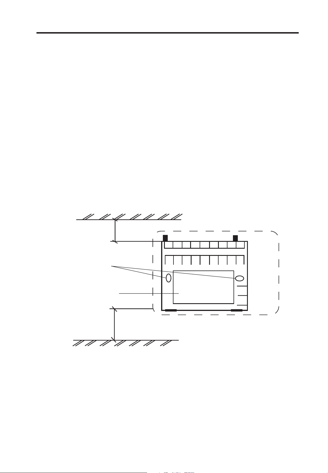
WP75-RF installation
Select a position for the WP75-RF that provides easy access to
the unit (it could be used on a daily basis by the user, so the
display needs to be clearly visible) and bearing in mind that
the maximum distance between the thermostat and sensor is
10 metres.
Prepare the xing position to provide access for the sensor
cable through the rear of the wallplate.
If the cable is to be surface xed note that it can only enter
the WP75-RF from the bottom through the positions shown
below.
30mm min
Wall or plaster
box mounting
holes
Aperture for
rear entry
Terminals
A
B
Outline of entry
Thermostat Installation
Clearance for
screwdriver access
Fix the wallplate so that the control module can be easily
Knockout for bottom
cable entry
attached or removed. Make the sensor wiring connections as
shown in the wiring diagram on page 7.
Before attaching the control module to the wallplate set the
DIL switch, located in a recess on the rear of the module, to
select whether the WP75-RF will be a 7 day controller or a 5/2
day (weekday/weekend) controller. Move both switches to
4
the desired position.
Page 5
Attach the control module to the wallplate by placing the
slots in the top of the module over the lugs on the top edge
of the wallplate and hinging down until the slot in the bottom
edge of the module locates over the screw attached to the
wallplate. Tighten the screw.
CS1 Sensor installation
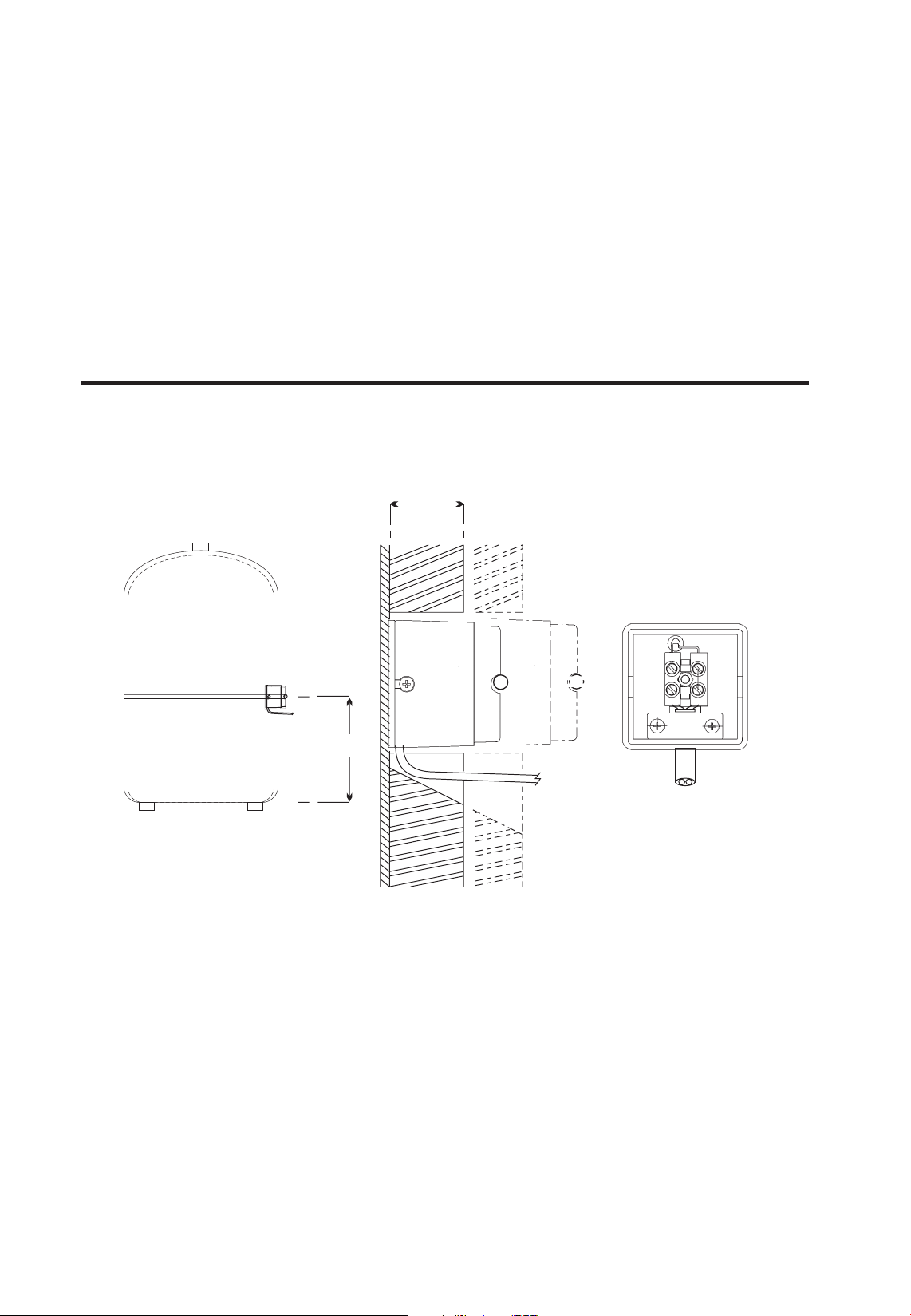
Gas or Oil red Boiler Systems
The sensor should be tted to the side of the domestic hot
water cylinder, half way up from the bottom.
1/2 cylinder
height
For insulation thicker than 25mm
and up to 55mm thick, use the
extra cover supplied as a spacer to
ensure that the sensor is held in
firm contact with the cylinder wall.
IMPORTANT
1. Ensure cylinder wall is clean
2. Use heat transfer paste
provided
Select the xing position and remove su cient insulation to
Sensor Installation
ensure that the sensor element can make close contact with
the surface of the cylinder wall.
Clean away all traces of insulation and ensure both cylinder
wall and sensor are clean.
Before mounting the sensor, coat the copper foil on the contact
surface of the sensor with the heat conducting paste supplied.
The sensor must be connected to the WP75-RF using double
insulated cable greater than 0.75mm
2
.
5
Page 6
Connect the cable to the sensor terminals and replace the
cover. Place the sensor on the cylinder and clamp tightly to
the cylinder using the strap provided.
Cable entry is from behind if tted to a single gang ush box,
or from above, below or from the left if surface xed cable is
used.
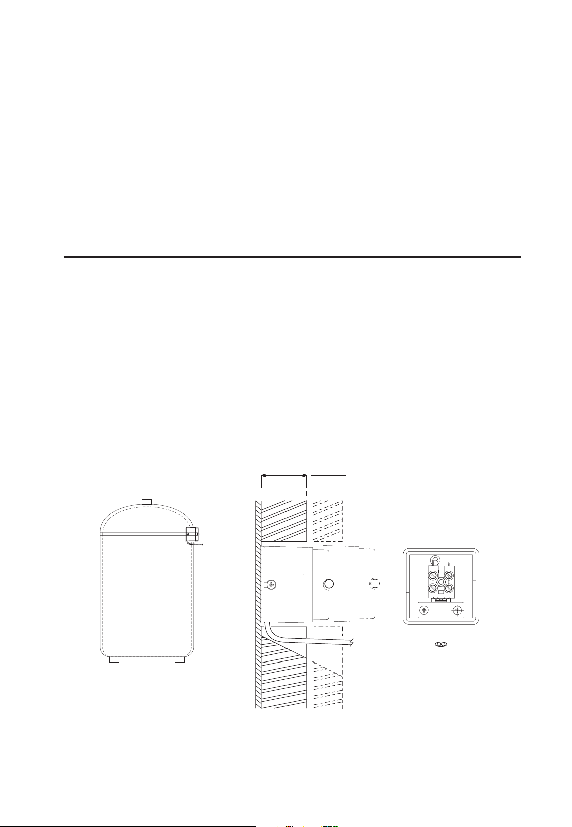
Fast Recovery Cylinder Heater Systems
The sensor should be tted to the side of the domestic hot
water cylinder just below the top seam.
Select the xing position and remove su cient insulation to
ensure that the sensor element can make close contact with the
surface of the cylinder wall (see opposite).
Clean away all traces of insulation and ensure both cylinder
wall and sensor are clean.
For insulation thicker than 25mm
and up to 55mm thick, use the
extra cover supplied as a spacer
to ensure that the sensor is held
in firm contact with the cylinder wall.
Sensor Installation
IMPORTANT
1. Ensure cylinder wall is clean
2. Use heat transfer paste
provided
Before mounting the sensor, coat the copper foil on the
contact surface of the sensor with the heat conducting paste
supplied.
6
Page 7

The sensor must be connected to the WP75-RF using double
insulated cable greater than 0.75mm2.
Connect the cable to the sensor terminals and replace the
cover. Place the sensor on the cylinder and clamp tightly to
the cylinder using the strap provided.
Thermostat Wiring
WP75-RF
Transmitter
A B
L
N
RX Receiver Wiring
RX1 Receiver
Receiver
NL1234
2-port zone valve
L N
Boiler
L N
Pump
RX1
ELECTRONICS
N
L
1
2
COM
3
ZONE
1 ON
4
ZONE
1 OFF
RX2 & RX3
ELECTRONICS
B
N
C1
L
A
345
2
COM
ZONE
1 ON
ZONE
1 OFF
ZONE
2 ON
TERMINAL 6
RX3 ONLY
6
ZONE
3 ON
Note 1) For mains voltage operated systems link terminal 2 to mains live supply.
2) Power supply to unit must not be switched by timeswitch
Wiring
7
Page 8

Commissioning
If the thermostat and the receiver have been supplied together
in a combined pack, the units have been paired in the factory
and no commissioning is required (RX1 only).
To tune the RX receiver to the frequency of the thermostat signal,
follow steps 1-5 below.
(1)
1. WP75-RF
Press the recessed RESET button, using
a non-metallic object, to reset the unit.
2. Press & hold the recessed LEARN
button for 3 seconds, using a nonmetallic object.
(2)
NOTE: Thermostat now transmits
continuously for 5 minutes.
3. RX1
Press and hold buttons PROG and CH1
for 3 seconds until green light ashes
once.
4. RX2 (if applicable)
Stat 1 - perform steps 1-3
Stat 2 - wait 5 mins, perform steps 1-2,
Commissioning
then press PROG + CH2 on RX2
RX3 (if applicable)
Stat 1 - repeat step 2-3 for CH1
Stat 2 - wait 5 mins, perform steps 1-2, then press PROG + CH2
on RX3
Stat 3 - wait 5 mins, perform steps 1-2, then press PROG + CH3
on RX3
5. WP75-RF
Press or - the unit will revert to
normal operation.
8
Page 9

The text below has been edited and approved by the Plain English
Campaign, who has issued a Crystal Mark to be displayed with it.
What is a cylinder thermostat?
... an explanation for householders.
A cylinder thermostat switches on and o the heat supply from the
boiler to the hot-water cylinder. It works by sensing the temperature
of the water inside the cylinder, switching on the water heating
when the temperature falls below the thermostat setting, and
switching it o once this set temperature has been reached.
Turning a cylinder thermostat to a higher setting will not make the
water heat up any faster. How quickly the water heats up depends
on the design of the heating system, for example, the size of boiler
and the heat exchanger inside the cylinder.
The water heating will not work if a time switch or programmer has
switched it o . And the cylinder thermostat will not always switch the
boiler o , because the boiler sometimes needs to heat the radiators.
Cylinder thermostats are usually tted between one quarter and
one third of the way up the cylinder. The cylinder thermostat will
have a temperature scale marked on it, and it should be set at
between 60°C and 65°C, then left to do its job. This temperature is
high enough to kill o harmful bacteria in the water, but raising the
temperature of the stored hot water any higher will result in wasted
energy and increase the risk of scalding.
If you have a boiler control thermostat, it should always be set
to a higher temperature than that of the cylinder thermostat. In
most boilers, a single boiler thermostat controls the temperature
of water sent to both the cylinder and radiators, although in some
there are two separate boiler thermostats.
What is a cylinder thermostat?
Please note: The WP75-RF is a programmable cylinder thermostat.
9
Page 10

User Instructions
Your programmer
The WP75-RF is a wireless programmable thermostat, designed to
control the temperature of the water in your hot water cylinder.
Heating water to a temperature which is higher than necessary
is wasteful of energy. The WP75-RF lets you heat your water to a
temperature you require, just at the times you need it. You can
programme up to three ON times and temperatures per day.
It also features a BOOST function, to provide an instant tank of hot
water, as well as a Hot Water Available function, which tells you
how much hot water you have available in your cylinder.
How to read the display
Overview & reading the display
10
Page 11

Preset Programmes
Your WP75-RF comes ready programmed with a set of operating
times and temperatures which often suit most people.
Weekdays (Mon-Fri) Weekend (Sat-Sun)
Event Time Temp °C Event Time Temp °C
1 06:30 55.0 1 07:30 55.0
2 08:30 OFF 2 09:30 OFF
3 12:30 45.0 3 11:30 45.0
4 13:30 OFF 4 13:30 OFF
5 16:00 55.0 5 16:30 55.0
6 22:00 OFF 6 22:30 OFF
Please note: In order to reduce the risk of Legionella infection, it is
recommended that water temperature be set to not less than 60°C for
at least one event each day.
If you want to change any of these settings you can do so by
following the instructions on pages 13-15.
First, follow the steps on page 11-12 to set the correct time and date.
Before you start
Open the ap on the front of your
programmer. Using a non-metallic
Preset Programmes & Resetting the unit
object, press the recessed RESET button,
until you hear a click and the display
goes momentarily blank.
This will reinstate the preset programmes
and will set the time to 12:00 on Day 1.
BOOST
ON
OFF
AUTO
ALLDAY
11
Page 12

Setting the Time & Day
Press PROG until the time and day number
begin to blink in the display.
DAY - Press DAY until correct day is shown
(1=Monday, 2=Tuesday etc).
TIME - Press + and - to change time (press
and hold to change in 10 min increments).
Press PROG again to accept the settings.
To change TIME
To
change
DAY
Running your programme
If you are happy to use the preset
programmes on page 11, you don’t need to
do anything else.
Press PROG until colon ashes in display.
Setting the Time/Day & Running the programme
Your unit is in RUN mode and your hot
water will be heated according to the preset
programmes.
12
Page 13

Before you change the preset programme
Your installer will have set your unit to operate in either 7-day
mode or 5/2 day mode.
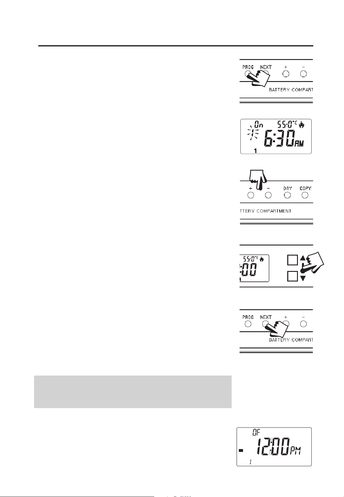
To tell which mode your unit is set press PROG until Event 1 ashes
in the display.
If your display looks like this, your unit is
in 7-day mode and you can programme
di erent settings for each day of the week
(see page 14).
If your display looks like this, your unit is in
5/2 day mode and you can enter one set
of programmes for weekdays and another
set for weekends (see page 15).
Please Note
The unit must be programmed in sequence and ON/OFF
times cannot be programmed out of sequence.
If you want to leave a preset time as it is, simply press
PROG to move on to the next setting.
Changing the programmes
!
If at any time you get confused and need to reset the
unit to the preset programmes, press and hold the
recessed RESET button, using a non-metallic object
(see page 11).
13
Page 14
Programming in 7-day mode
(separate programmes for each day of the week)
a) Press PROG until Event 1 ashes, then
press DAY to move from current day to
Day 1 (Event 1, Day 1).
b) Amend the time and temperature as
follows:
i) Use + and – buttons to alter time
(press and hold to change in 10 min
increments).
ii) Use and buttons to alter the water
temperature in 0.5°C (1°F) steps.
iii) Press NEXT to advance to next preset time
and temperature (Event 2, Day 1).
iv) Repeat steps i, ii & iii above for Events 2,
3, 4, 5 & 6.
c) When all 6 events are correct, press DAY
to programme events for Day 2.
(If you wish to repeat the previous day’s
Programming in 7-day mode
d) Repeat steps i-iii above to programme
programme, simply press COPY) .
(or COPY) events for Days 3, 4, 5, 6 & 7.
Press PROG until the colon in the LCD display
starts to ash.
The unit is now in RUN mode and your
hot water will come on and go o at the
programmed times.
Proceed to page 16.
14
Page 15

Programming in 5/2 day mode
(one set of programmes for weekdays, another set for weekends)
For Days 1-5 (weekdays)
a) Press PROG until Event 1 ashes in
display (Event 1, Days 1,2,3,4,5).
b) Use + and – buttons to alter time
(press and hold to change in 10 min
increments).
c) Use and buttons to alter the water
temperature in 0.5°C (1°F) steps.
d) Press NEXT to move to next preset time &
temperature (Event 2, Days 1,2,3,4,5).
e) Repeat steps b, c & d for programming
Events 3, 4, 5 & 6.
For Days 6-7 (weekends)
Press PROG until Event 1 ashes in
display (Event 1 Days 6-7).
Repeat steps b, c and d above to
programme time and temperature
events for the weekend.
Programming in 5/2-day mode
Press PROG until the colon in the LCD display
starts to ash.
The unit is now in RUN mode and your
hot water will come on and go o at the
programmed times.
Proceed to page 16.
15
Page 16

Running your programme
To run the hot water programme press
the SELECT button.
As you press the SELECT button a bar in
the display will move to indicate which
RUN mode has been selected.
BOOST
ON
OFF
AUTO
ALLDAY
The four available functions and their meanings are as follows:
ON = the water will be heated continuously to the
highest temperature set for the day shown on the
display.
OFF = the water will not be heated at all (unless the
BOOST button is pressed - then the water will be
heated to the highest temperature set for the day.
When this temperature is achieved the thermostat
with revert to OFF.)
Running your programme
AUTO = the water will come on and go o at the
programmed times.
ALLDAY = the water will remain on from setting 1
(1st ON) through to setting 6 (last OFF), at the highest
temperature set for the day.
Select the option you require, depending on your circumstances,
time of year, etc.
16
Page 17

BOOST function
Sometimes you may have an immediate requirement for hot water
which is outside the set programme.
For instant hot water press the BOOST button.
If the system is OFF when you press BOOST - the water
will heat up to the highest setting of the day and then turn
itself o again.
If the system is ON when you press BOOST - the water will
heat up to the highest setting of the day (but only if the
current programmed temperature is lower).
Hot Water Available function
Sometimes you may need to know how much hot water there is
in your tank. With the WP75-RF a simple ‘hot water available’
function is included.
To see an approximate indication of how much hot
BOOST Function and Hot Water Available Function
water is currently stored press the and buttons
simultaneously.
The number of horizontal bars displayed indicates approximately
how much hot water is available at the temperature shown.
17
Page 18

Cylinder more than full of
hot water.
Cylinder between and full
of hot water.
Cylinder less than full of hot
water.
Changing clocks forward & back
Open the ap on the front of the unit to
reveal the programming buttons.
To change from Summer to Winter
(clocks back) -
press and hold - button
To change from Winter to Summer
(clocks forward) -
Hot Water Available function and Changing Clocks
press and hold + button
NOTE: After the rst time this change has been made this
feature will only allow the clock to be changed in the opposite
direction.
Take care when making this change for the rst time. If
it is made in the wrong direction the unit will have to be
reset and any user-settings re-entered.
(See pages 11-12 on how to Reset the unit and how to set
the Time & Day)
18
!
Page 19

Battery Replacement
When batteries are low a battery
symbol will ash in the LCD display.
You have 2 weeks to replace the
battery before the unit will switch o .
When changing batteries, remove old batteries and insert new
ones within one minute and programming will not be lost.
IMPORTANT: use 2 x AA size (LR6) high quality alkaline dry
cell batteries.
Battery replacement
!
NB. If the display ever goes blank during normal operation, the
batteries will need to be renewed, the unit reset and the time and
programmes reset.
19
Page 20

Still having problems?
Call your local heating engineer:
Name:
Tel:
For problems relating to your heating controls ...
Visit our website:
www.danfoss-randall.co.uk
Email our technical department:
drl_technical@danfoss.com
Call our technical department
0845 121 7505
(8.45-5.15 Mon-Thurs, 8.45-4.45 Fri)
For a large print version of these instructions
please contact the Marketing Services
Department on 0845 121 7400.
20
Part No 34248v06 07/07
Danfoss Randall Ltd
Ampthill Road
Bedford
MK42 9ER
Tel: 01234 364621
Fax: 01234 219705
 Loading...