

Page 1
Installation instructions WP39 Weatherproof Enclosures for 2½” to 4”AB-QM Valves
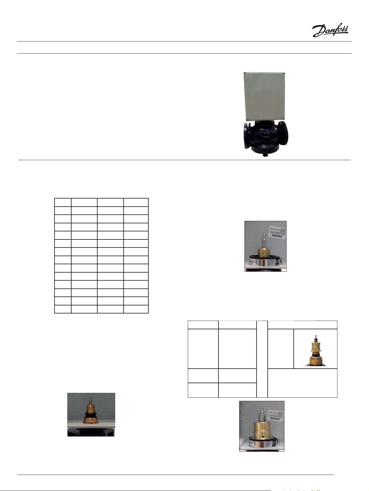
The WP39 is a NEMA rated 6P indoor/outdoor enclosure
designed speci cally for 2½” to 4” AB-QM valve bodies
mounted with the AME435QM (code no. 082H0171), AMV435
(code no. 082H0162) or AME25 series (code no. 082H3041 or
082H3038) of motorized actuators.
Enclosed:
(1) Black rubberized collar
(1) Size 24 hose clamp
Required:
(1) Weather tight ½” electrical conduit
Step 1
Con rm the proper ow percentage setting is correct. (Refer to
the AB-QM valve instructions for the proper methods to set the
valve ow percentage.
2½” 3” 4”
40% 34.0 48.0 66.0
45% 38.3 54.0 74.3
50% 42.5 60.0 82.5
55% 46.8 66.0 90.8
60% 51.0 72.0 99.0
65% 55.3 78.0 107.3
70% 59.5 84.0 115.5
75% 63.8 90 .0 123. 8
80% 68.0 96.0 132.0
85% 72.3 102.0 140.3
90% 76.5 108.0 148.5
95% 80. 8 114.0 156.8
100% 85.0 120.0 165.0
Step 2
Install a weather tight ½” electrical conduit to the pre-drilled
hole on the side of the enclosure.
Slide the neck of the valve through the large hole of the
enclosure.
Step 3
Remove the hose clamp from the collar. While steadying the
enclosure, fully seat the collar to the neck of the valve. Push
down on the collar to keep it ush to the enclosure.
Slide the hose clamp to the bottom of the collar and tighten
the clamp.
Step 4
Depending on the actuator to be installed to the valve body, an
adapter may be required. In the event an adapter is required,
install the brass adapter to the valve and then the stem
extension as per the adapter instructions.
Actuator Code No.
AME 25
series
082H3075 (SU)
082H3038 (SD)
Required Adapter
003Z0694
>
AME 435QM 082H0171
None required
AMV 435 082H0162
1
© Danfoss 08/2014
Page 2
Installation instructions WP39 Weatherproof Enclosures for 2½” to 4”AB-QM Valves
Step 5
Pull the wire through the conduit tting and provide enough
slack to allow for the removal of the actuator from the
weatherproof enclosure. Based upon the actuator’s installation
instructions pre-wire the the actuator. Do not power the
actuator prior to mounting to the valve.
Step 6a (AME435QM or AMV435 series)
Slide the actuator onto the valve with the longer portion of the
actuator pointing towards the electrical conduit. Follow the
installation procedures to mount the actuator to the valve.
Step 7
Power the actuator and con rm the initial commisioning of the
actuator to the valve. The actuator will cycle full open to close
as it learns the required stem travel distance.
Step 8
Align the enclosure’s cover and tighten the 4 screws of the
enclosure. Make sure the cover makes contact to the gasket
when tightening.
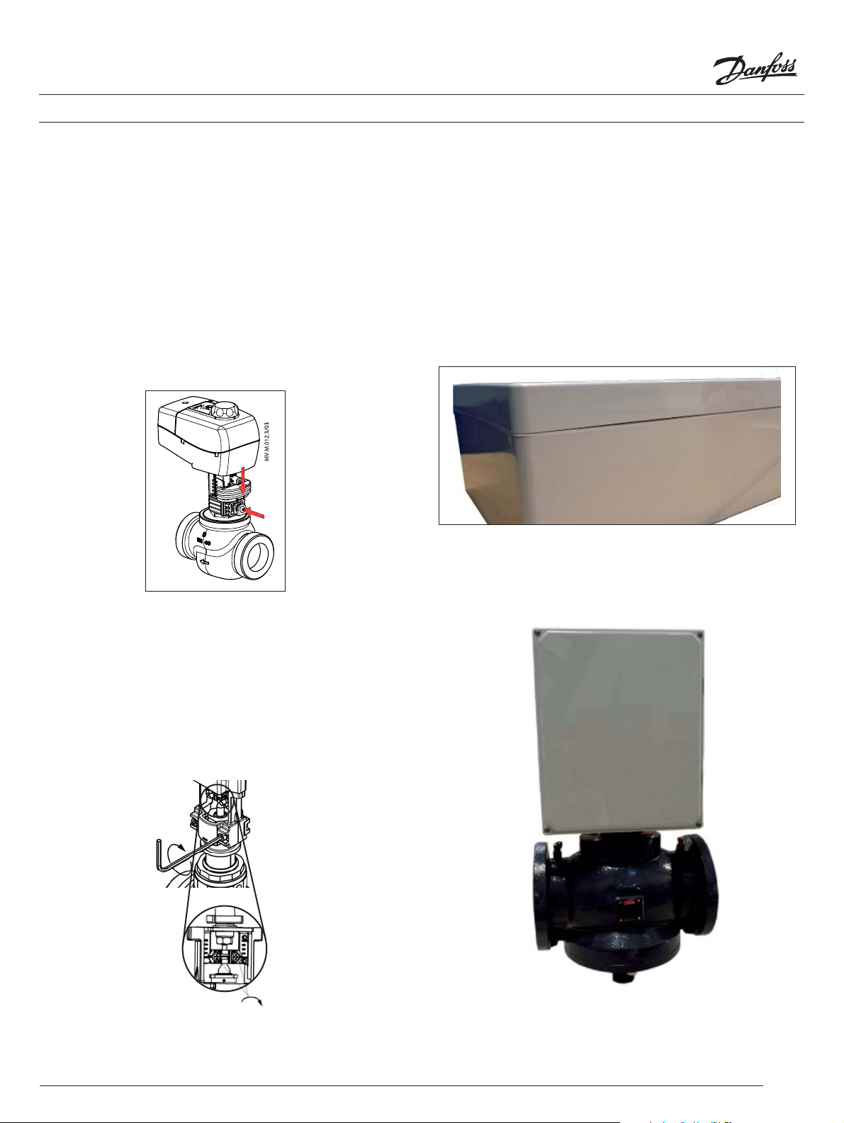
Step 6b (AME25 SU/SD series)
With a 4mm Allen, loosen the base of the actuator to
accommodate the actuator to the adapter. Fully seat the AME25
series actuator to the valve and tighten the screws.
If the valve stem impedes the seating of the actuator, either
raise or lower the stem or insert it within the actuator stem
clamp.
4mm
2
© Danfoss 08/2014
 Loading...