

Page 1
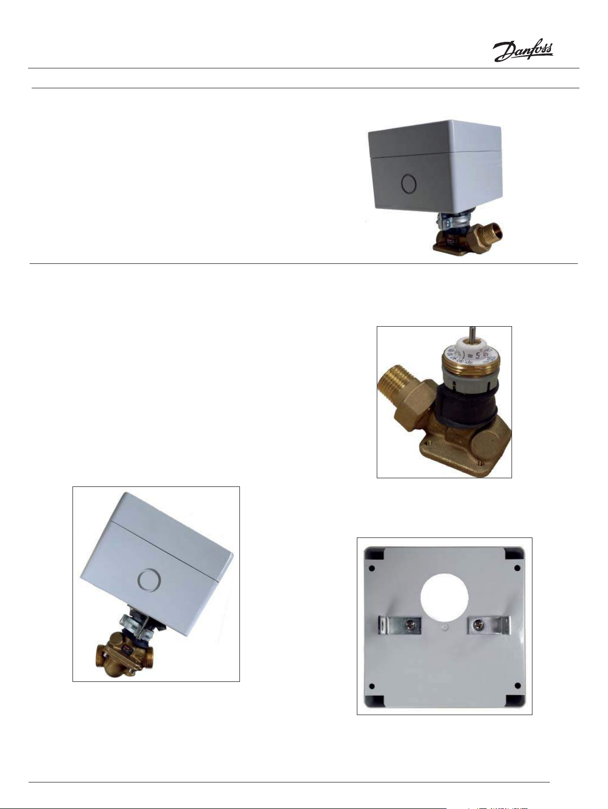
Installation instructions WP37 Weatherproof Enclosures for ½” to 1¼” AB-QM Valves
The WP37 weatherproof enclosure is designed speci cally for
½” to 1¼” AB-QM valve bodies mounted with the AMI 140, AME
110NL and the AMV 110NL motorized actuators.
Enclosed:
(1) Galvanized clamp
(2) #8 Stainless steel screws
(2) L brackets
(2) 3/8” wide gasket
(1) 3/4” wide gasket
(4) Enclosure screws
Required:
(1) Weather tight ½” electrical conduit
Step 1
Con rm the proper ow percentage setting is correct for the
valve. (Refer to the AB-QM valve instructions for the proper
method to set the valve ow percentage.)
Step 2
Determine which of the two electrical knock outs will be used
to wire the actuator. The photo below re ects the completed
assembly of the weatherproof enclosure.
Knock-out the appropriate hole and install a weather tight 1/2”
electrical conduit.
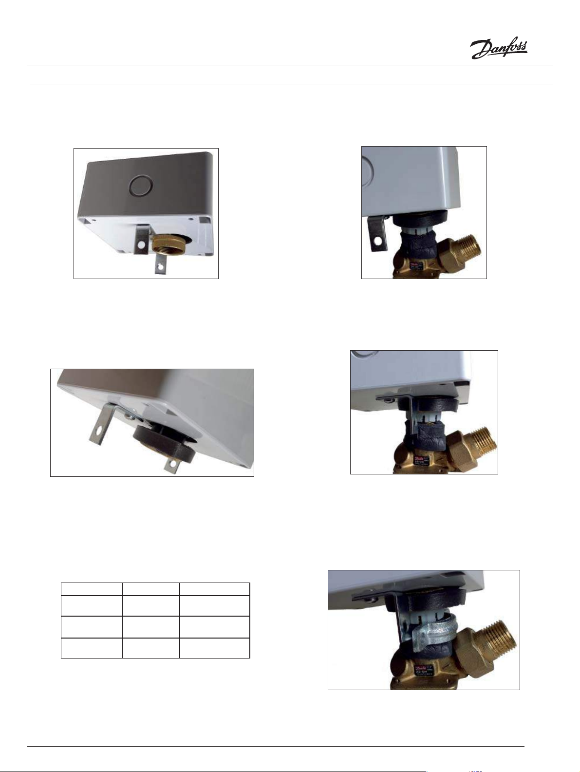
Step 3
Apply the 3/4” wide gasket to the neck of the valve, placing the
edge of the gasket below the grey adjustment ring.
Step 4
Install the L bracket to the enclosure as seen below.
1
© Danfoss 08/2013
Page 2
Installation instructions WP37 Weatherproof Enclosures for ½” to 1¼” AB-QM Valves
Step 5
Place the adjustment knob of the actuator through the bottom
of the enclosure.
Step 6
Align and press a single 3/8” wide gasket to the upper
portion of the adjustment nut of the actuator.
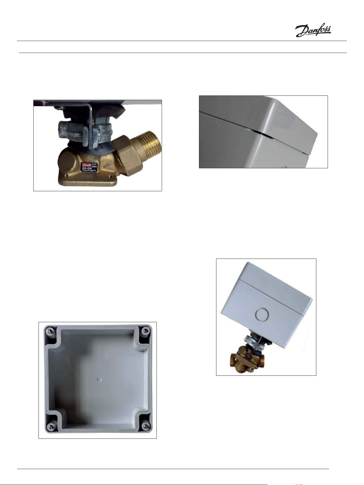
Step 8
Orient the shorter portion of the actuator and enclosure toward
the outlet of the valve. Tighten the actuator to the valve.
Step 9
Rotate the L brackets 90 degrees towards the outlet of the
valve.
Step 7
If any necessary actuator adapter is required for the mounting
of the motor actuator, install the adapter to the valve.
(Refer to adapter installation instructions)
Actuator Code No. Required Adapter
AMI 140 082H80 48 003Z0257
AME 110NL 082H8056 None
AMV 110NL 082H8057 None
2
© Danfoss 08/2013
Step 10
Disassemble the clamp assembly and place the curved half
below the grey adjustment ring. The curved half should point
to the outlet side of the valve body.
Page 3
Installation instructions WP37 Weatherproof Enclosures for ½” to 1¼” AB-QM Valves
Step 11
Install the L bracket in between the clamp assembly.
Step 12
Wire the motor actuator according to the actuator installation
instructions. (Refer to actuator instructions)
Step 15
Tighten the cover to the enclosure. Con rm that the silicone
gasket is in full contact
Step 13
Pre-install the 4 cover screws to the cover of the enclosure.
Step 14
Looking onto the other side of the cover, identify the shorter
length of the silicone gasket. Align this side of the cover to the
side of the enclosure with the knockout electrical conduit.
3
© Danfoss 08/2013
 Loading...