

Page 1
Installation instructions WP35 Weatherproof Enclosures for 1½” & 2”AB-QM Valves
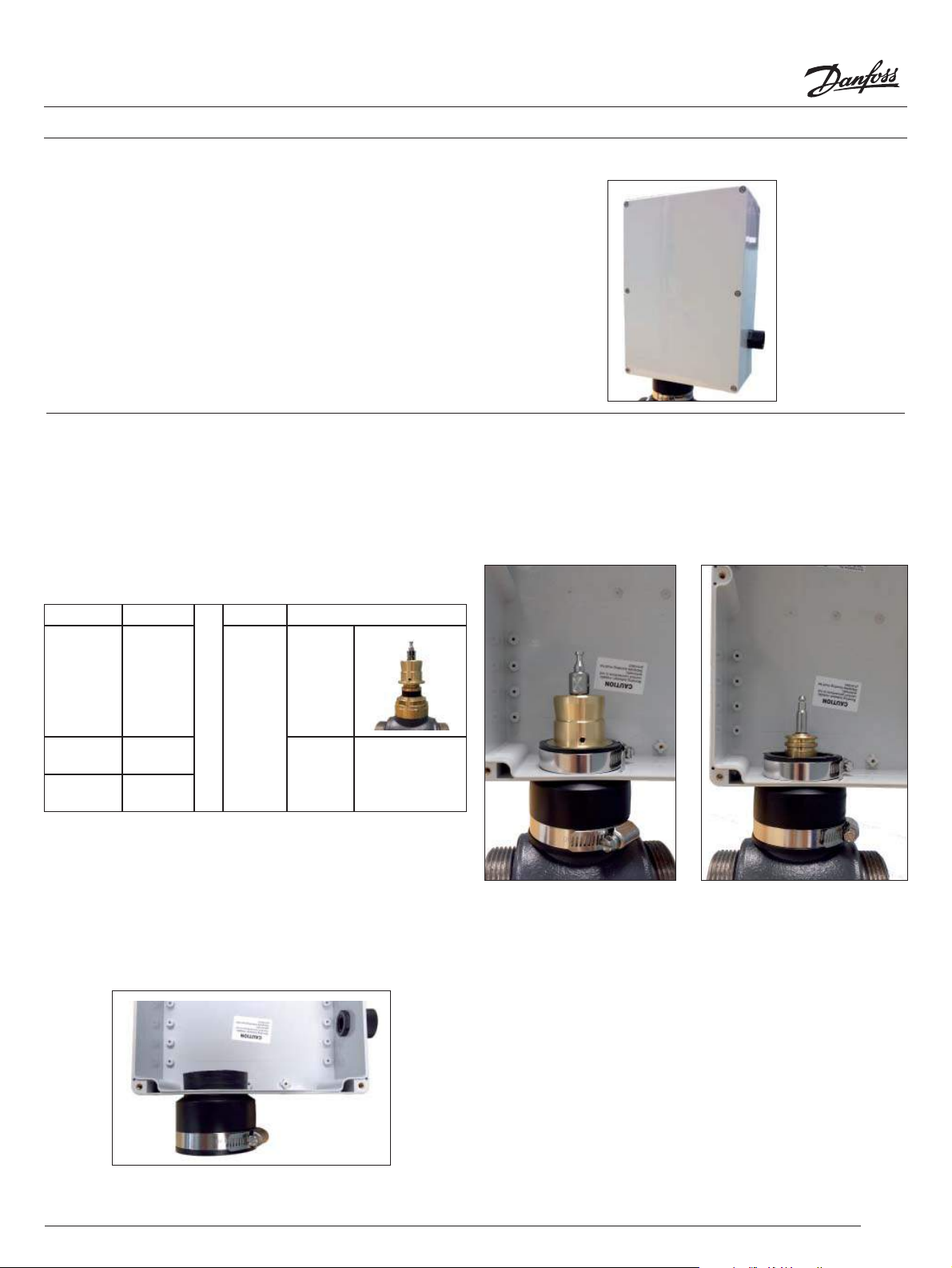
The WP35 weatherproof enclosure is designed speci cally 1½”
and 2” AB-QM valve bodies mounted with either the AME15QM
or AME435QM motorized actuators.
Enclosed:
(1) Black rubberized collar
(1) Size 40 hose clamp
(1) Size 32 hose clamp
Required:
(1) Weather tight ½” electrical conduit
Step 1
Con rm the proper ow percentage setting is correct. (Refer to
the AB-QM valve instructions for the proper methods to set the
valve ow percentage.
Step 3
Fully seat the collar by pushing down the collar to the AB-QM
valve body. Tighten the hose clamp.
If any necessary valve adapters are required for the mounting
of the motor actuator, installed the adapter to the valve.
(Refer to adapter installation instructions)
Actuator Code No.
AME 15QM 082H3075
AME 435QM 082H0171
AMV 435 082H0162
Valve Required Adapter
065Z0311
003Z0780
>
003Z0781
None
Step 2
Remove the smaller (size 32) hose clamp from the collar and
install the collar into the bottom of the enclose. Slide the collar
until it rests with the bottom of the enclosure.
Install a weather tight ½” electrical conduit to the pre-drilled
hole on the side of the enclosure.
Slide the smaller clamp onto the collar and tighten the clamp.
For AME 15QM For AME 435QM / AMV 435
Step 4
Wire the actuator based upon the actuator’s installation
instructions. Provide enough wire slack to allow for the removal
of the actuator from the weatherproof enclosure.
1
© Danfoss 08/2013
Page 2
Installation instructions WP35 Weatherproof Enclosures for 1½” & 2”AB-QM Valves
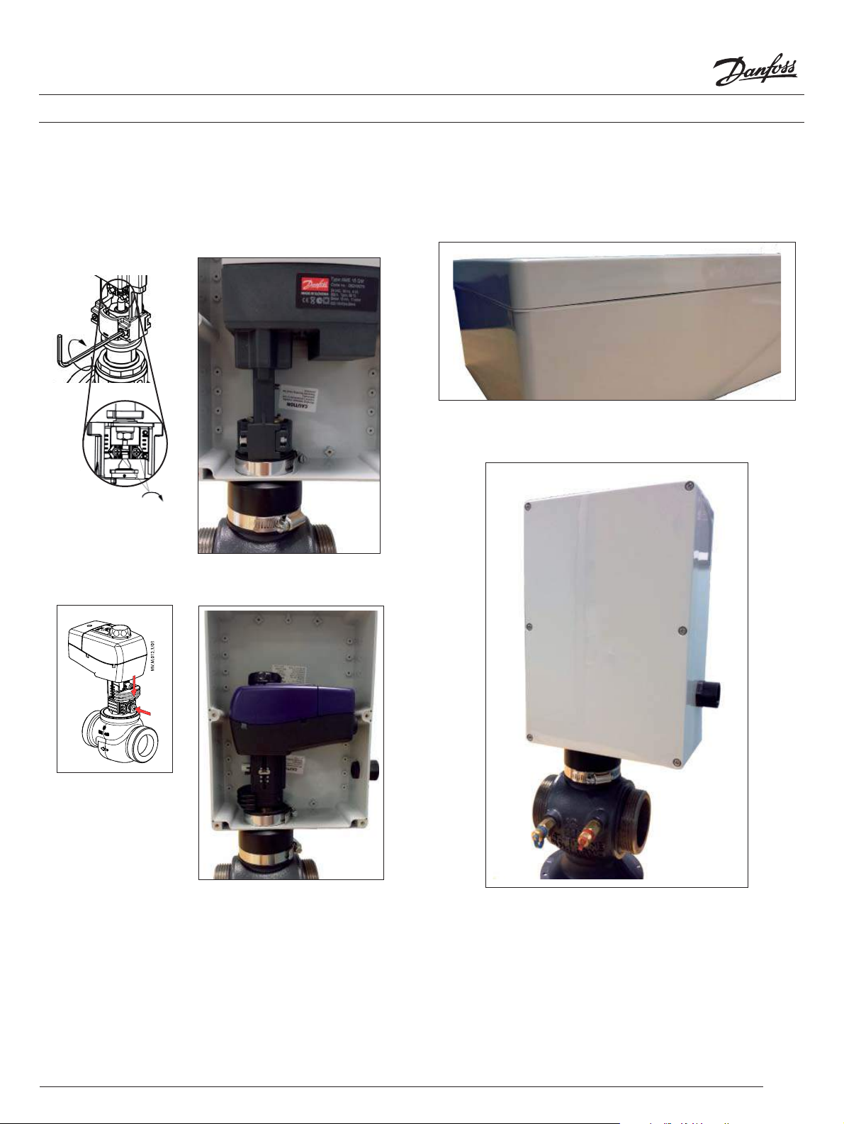
Step 5
Slide the actuator onto the valve with the longer portion of the
actuator pointing towards the electrical conduit. Follow the
installation procedures to mount the actuator to the valve.
AME 15QM
4mm
Step 7
Align the enclosure’s cover and tighten the 6 screws of the
enclosure. Make sure the cover makes contact to the silicone
gasket when tightening.
AME 435QM
Step 6
Power the actuator and con rm the initial commisioning of the
actuator to the valve. The actuator will cycle full open to close
as it learns the required stem travel distance.
2
© Danfoss 08/2013
 Loading...