

Page 1
Technical Information
WD, WP and WR Series
Orbital Motors
www.danfoss.com
Page 2

Technical Information
Orbital Motors Type WD, WP and WR
Revision history Table of revisions
Date Changed Rev
December 2019 Conversion to CMS/ET Danfoss layout. 0201
June 2017 First edition 0101
2 | © Danfoss | December 2019 BC267362166283en-000201
Page 3

Technical Information
Orbital Motors Type WD, WP and WR
Contents
Technical Information
Operating Recommendations..................................................................................................................................................... 4
Oil Type...........................................................................................................................................................................................4
Fluid Viscosity and Filtration...................................................................................................................................................4
Installation and Start-up...........................................................................................................................................................4
Motor Protection.........................................................................................................................................................................4
Hydraulic Motor Safety Precaution.......................................................................................................................................4
Motor/Brake Precaution........................................................................................................................................................... 5
Motor Connections..........................................................................................................................................................................6
Product Testing.................................................................................................................................................................................7
Allowable Bearing and Shaft Loading.......................................................................................................................................7
Vehicle Drive Calculations.............................................................................................................................................................9
Induced Side Load.........................................................................................................................................................................12
Hydraulic Equations......................................................................................................................................................................13
Shaft Nut Information...................................................................................................................................................................14
Optional Motor Features
Speed Sensor Options..................................................................................................................................................................16
Freeturning Rotor Option........................................................................................................................................................... 19
Valve Cavity Option.......................................................................................................................................................................19
Slinger Seal Option........................................................................................................................................................................20
WD Product Line
WD Introduction.............................................................................................................................................................................21
WD Functional Charts...................................................................................................................................................................22
WD 145/146 Series.........................................................................................................................................................................28
145/146 Series Housings........................................................................................................................................................28
145/146 Series Technical Data.............................................................................................................................................30
145/146 Series Shafts.............................................................................................................................................................. 33
145/146 Series Order Codes................................................................................................................................................. 35
WP Product Line
WP Introduction............................................................................................................................................................................. 36
WP Functional Charts................................................................................................................................................................... 37
155/156 Series.................................................................................................................................................................................45
155/156 Series Housings........................................................................................................................................................45
155/156 Series Technical Data.............................................................................................................................................51
155/156 Series Shafts.............................................................................................................................................................. 55
155/156 Order Codes.............................................................................................................................................................. 57
WP 157 and 158 Series................................................................................................................................................................. 60
WP 157 and 158 Series Housings........................................................................................................................................60
WP 157 and 158 Series Technical Information...............................................................................................................60
WP 157 and 158 Series Shafts.............................................................................................................................................. 62
WP 157 and 158 Series Ordering Information................................................................................................................64
WR Product Line
WR Product Line Introduction...................................................................................................................................................65
WR Displacement Performance................................................................................................................................................66
WR 251 and 252 Series.................................................................................................................................................................75
WR 251 and 252 Series Housings........................................................................................................................................75
WR 251 and 252 Series Technical Information...............................................................................................................76
WR 251 and 252 Series Shafts.............................................................................................................................................. 79
WR 251 and 252 Series Ordering Information................................................................................................................80
WR 255 and 256 Series.................................................................................................................................................................81
WR 255 and 256 Series Housings........................................................................................................................................81
WR 255 and 256 Series Technical Information...............................................................................................................85
WR 255 and 256 Series Shafts.............................................................................................................................................. 89
WR 255 and 256 Series Ordering Information................................................................................................................91
©
Danfoss | December 2019 BC267362166283en-000201 | 3
Page 4

Technical Information
Orbital Motors Type WD, WP and WR
Technical Information
Operating Recommendations
Oil Type
Hydraulic oils with anti-wear, anti-foam and demulsifiers are recommended for systems incorporating
Danfoss motors. Straight oils can be used but may require VI (viscosity index) improvers depending on
the operating temperature range of the system. Other water based and environmentally friendly oils may
be used, but service life of the motor and other components in the system may be significantly
shortened. Before using any type of fluid, consult the fluid requirements for all components in the system
for compatibility. Testing under actual operating conditions is the only way to determine if acceptable
service life will be achieved.
Fluid Viscosity and Filtration
Fluids with a viscosity between 20 - 43 cSt [100 - 200 S.U.S.] at operating temperature is recommended.
Fluid temperature should also be maintained below 85°C [180° F]. It is also suggested that the type of
pump and its operating specifications be taken into account when choosing a fluid for the system. Fluids
with high viscosity can cause cavitation at the inlet side of the pump. Systems that operate over a wide
range of temperatures may require viscosity improvers to provide acceptable fluid performance.
Danfoss recommends maintaining an oil cleanliness level of ISO 17-14 or better.
Installation and Start-up
When installing a Danfoss motor it is important that the mounting flange of the motor makes full contact
with the mounting surface of the application. Mounting hardware of the appropriate grade and size must
be used. Hubs, pulleys, sprockets and couplings must be properly aligned to avoid inducing excessive
thrust or radial loads. Although the output device must fit the shaft snug, a hammer should never be
used to install any type of output device onto the shaft. The port plugs should only be removed from the
motor when the system connections are ready to be made. To avoid contamination, remove all matter
from around the ports of the motor and the threads of the fittings. Once all system connections are
made, it is recommended that the motor be run-in for 15-30 minutes at no load and half speed to remove
air from the hydraulic system.
Motor Protection
Over-pressurization of a motor is one of the primary causes of motor failure. To prevent these situations,
it is necessary to provide adequate relief protection for a motor based on the pressure ratings for that
particular model. For systems that may experience overrunning conditions, special precautions must be
taken. In an overrunning condition, the motor functions as a pump and attempts to convert kinetic
energy into hydraulic energy. Unless the system is properly configured for this condition, damage to the
motor or system can occur.
To protect against this condition a counterbalance valve or relief cartridge must be incorporated into the
circuit to reduce the risk of overpressurization. If a relief cartridge is used, it must be installed upline of
the motor, if not in the motor, to relieve the pressure created by the over-running motor. To provide
proper motor protection for an over-running load application, the pressure setting of the pressure relief
valve must not exceed the intermittent rating of the motor.
Hydraulic Motor Safety Precaution
A hydraulic motor must not be used to hold a suspended load. Due to the necessary internal tolerances,
all hydraulic motors will experience some degree of creep when a load induced torque is applied to a
motor at rest. All applications that require a load to be held must use some form of mechanical brake
designed for that purpose.
4 | © Danfoss | December 2019 BC267362166283en-000201
Page 5
C
C
P109317
Technical Information
Orbital Motors Type WD, WP and WR
Technical Information
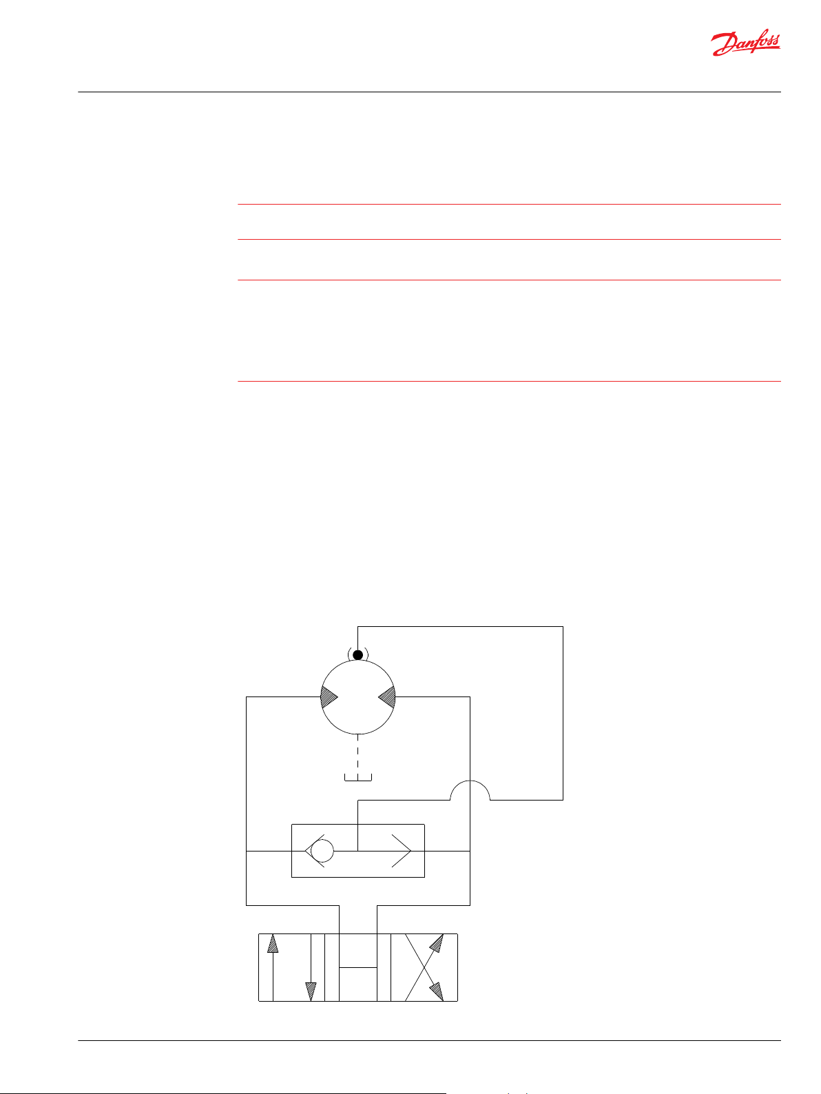
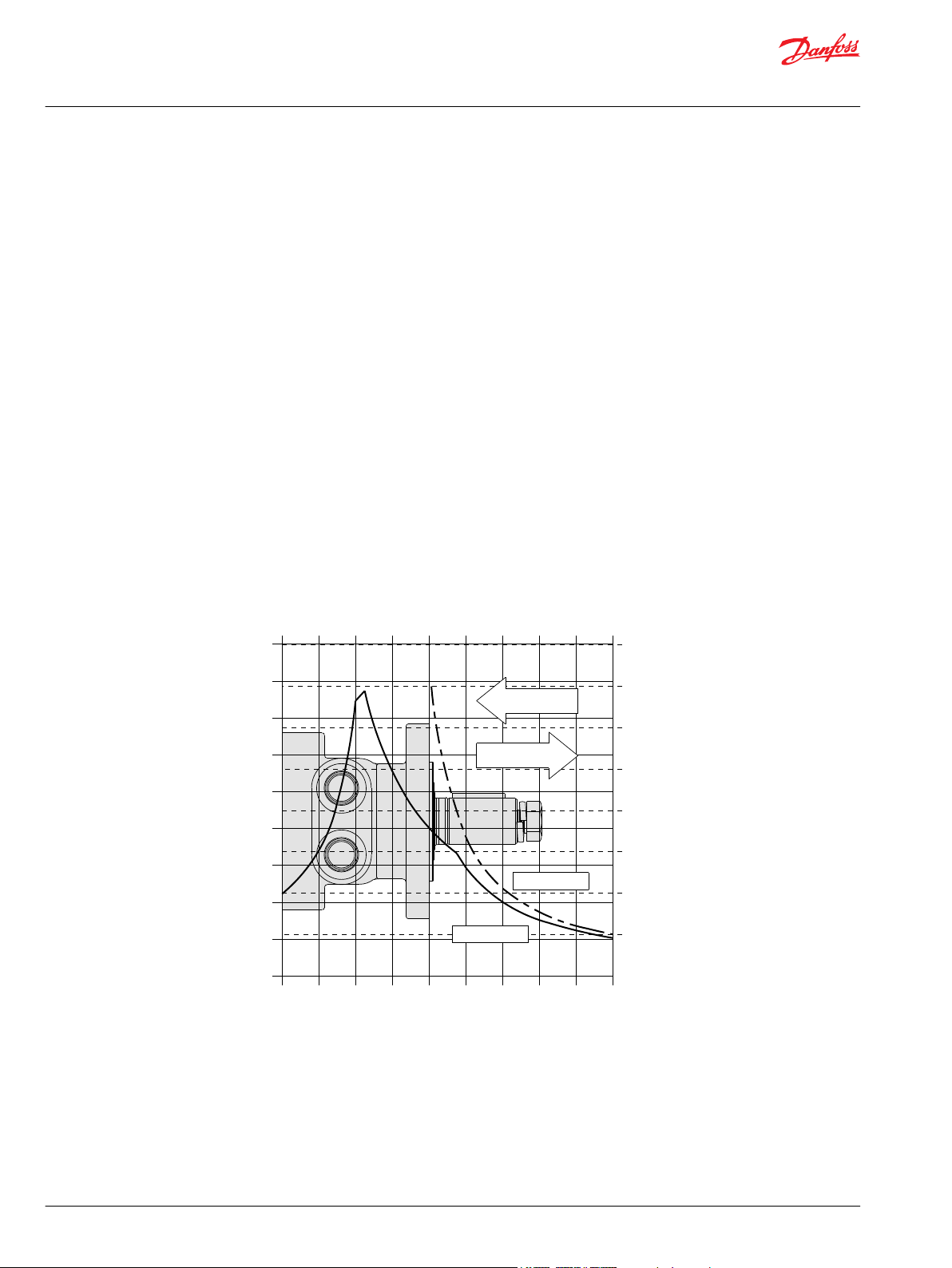
Motor/Brake Precaution
Caution
Danfoss’ motors/brakes are intended to operate as static or parking brakes. System circuitry must be
designed to bring the load to a stop before applying the brake.
Caution
Because it is possible for some large displacement motors to overpower the brake, it is critical that the
maximum system pressure be limited for these applications. Failure to do so could cause serious injury or
death. When choosing a motor/brake for an application, consult the performance chart for the series and
displacement chosen for the application to verify that the maximum operating pressure of the system
will not allow the motor to produce more torque than the maximum rating of the brake. Also, it is vital
that the system relief be set low enough to insure that the motor is not able to overpower the brake.
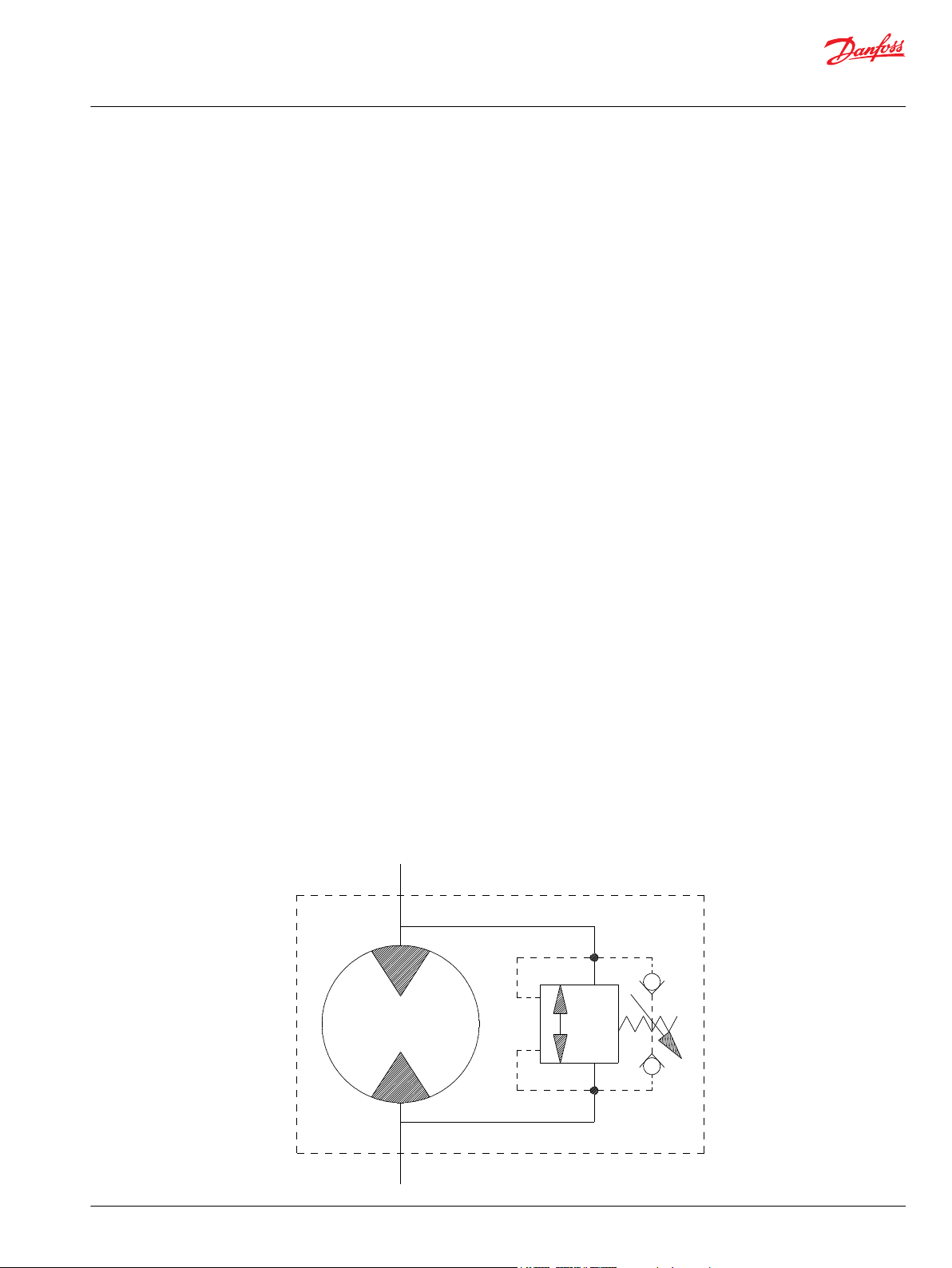
To ensure proper operation of the brake, a separate case drain back to tank must be used. Use of the
internal drain option is not recommended due to the possibility of return line pressure spikes. A simple
schematic of a system utilizing a motor/brake is shown in Typical Motor/Brake Schematic on page 5.
Although maximum brake release pressure may be used for an application, a 34 bar [500 psi] pressure
reducing valve is recommended to promote maximum life for the brake release piston seals. However, if
a pressure reducing valve is used in a system which has case drain back pressure, the pressure reducing
valve should be set to 34 bar [500 psi] over the expected case pressure to ensure full brake release.
To achieve proper brake release operation, it is necessary to bleed out any trapped air and fill brake
release cavity and hoses before all connections are tightened. To facilitate this operation, all motor/
brakes feature two release ports. One or both of these ports may be used to release the brake in the unit.
Motor/brakes should be configured so that the release ports are near the top of the unit in the installed
position.
Typical Motor/Brake Schematic
©
Danfoss | December 2019 BC267362166283en-000201 | 5
Page 6
W
P109318
P109319
Technical Information
Orbital Motors Type WD, WP and WR
Technical Information
Once all system connections are made, one release port must be opened to atmosphere and the brake
release line carefully charged with fluid until all air is removed from the line and motor/brake release
cavity. When this has been accomplished the port plug or secondary release line must be reinstalled. In
the event of a pump or battery failure, an external pressure source may be connected to the brake release
port to release the brake, allowing the machine to be moved.
Warning
It is vital that all operating recommendations be followed. Failure to do so could result in injury or death.
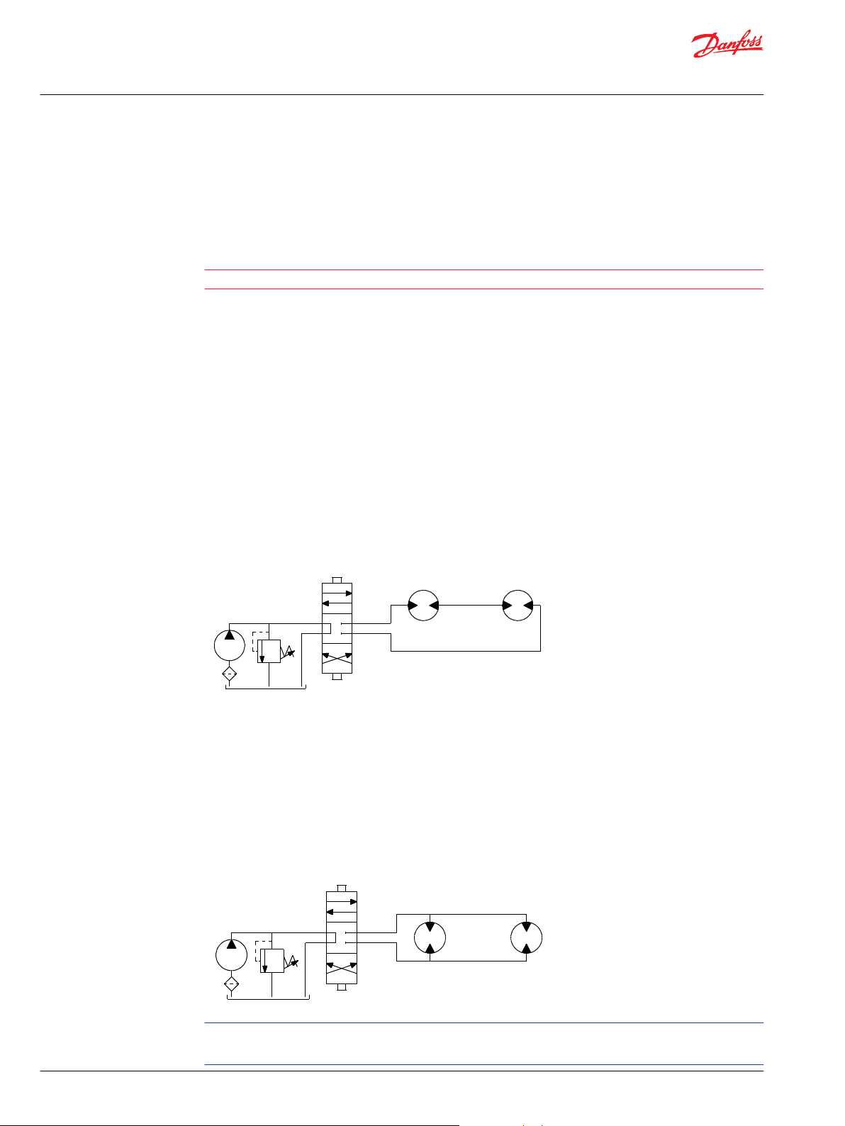
Motor Connections
There are two common types of circuits used for connecting multiple numbers of motors – series
connection and parallel connection.
Series Connection
When motors are connected in series, the outlet of one motor is connected to the inlet of the next motor.
This allows the full pump flow to go through each motor and provide maximum speed. Pressure and
torque are distributed between the motors based on the load each motor is subjected to. The maximum
system pressure must be no greater than the maximum inlet pressure of the first motor. The allowable
back pressure rating for a motor must also be considered. In some series circuits the motors must have an
external case drain connected. A series connection is desirable when it is important for all the motors to
run the same speed such as on a long line conveyor.
Series Circuit
Parallel Connection
In a parallel connection all of the motor inlets are connected. This makes the maximum system pressure
available to each motor allowing each motor to produce full torque at that pressure. The pump flow is
split between the individual motors according to their loads and displacements. If one motor has no load,
the oil will take the path of least resistance and all the flow will go to that one motor. The others will not
turn. If this condition can occur, a flow divider is recommended to distribute the oil and act as a
differential.
Parallel Circuit
The motor circuits shown above are for illustration purposes only. Components and circuitry for actual
applications may vary greatly and should be chosen based on the application.
6 | © Danfoss | December 2019 BC267362166283en-000201
Page 7
25
50
100
200
301
401
24
50
100
200
300
400
502
602
690
21
43
99
199
297
398
500
601
689
18
43
92
191
295
390
499
600
688
17
34
87
181
284
384
498
597
658
11
32
79
174
271
372
485
540
644
11
32
78
160
253
346
443
526
631
9
31
77
154
245
339
433
510
613
[127]
[140]
[139]
[127]
[113]
[91]
14
16
16
14
13
10
[262]
[286]
[280]
[275]
[262]
[243]
[212]
[177]
[127]
30
32
32
31
30
27
24
20
14
[543]
[559]
[563]
[572]
[557]
[536]
[511]
[482]
[445]
61
63
64
65
63
61
58
54
50
[806]
[839]
[857]
[872]
[853]
[826]
[790]
[767]
[741]
91
95
97
99
96
93
89
87
84
[1062]
[1099]
[1139]
[1155]
[1149]
[1125]
[1087]
[1060]
[1098]
120
124
129
131
130
127
123
120
124
[1285]
[1340]
[1390]
[1420]
[1420]
[1409]
[1379]
[1451]
[1369]
145
151
157
160
160
159
156
164
155
[1496]
[1579]
[1652]
[1643]
[1646]
[1654]
[1638]
[1711]
[1640]
169
178
187
186
186
187
185
193
185
[1693]
[1796]
[1865]
[1911]
[1930]
[1945]
[1883]
[2021]
[1918]
191
203
211
216
218
220
213
228
217
Flow - lpm [gpm]
17 [250] 35 [500] 69 [1000] 104 [1500] 138 [2000] 173 [2500] 207 [3000] 242 [3500]
Pressure - bars [psi]
21 [183] 41 [366] 83 [732] 124 [1099] 166 [1465] 207 [1831] 248 [2197] 290 [2564]
Theoretical Torque - Nm [lb-in]
Max.
Inter.
Max.
Cont.
76 cc [4.6 in3/rev.]
080
2 [0.5]
4 [1]
8 [2]
15 [4]
23 [6]
30 [8]
38 [10]
45 [12]
53 [14]
61 [16]
64 [17]
26
51
101
201
302
402
503
603
704
804
904
Theoretical rpm
Overall Efficiency -
70 - 100%
40 - 69%
0 - 39%
Intermittent Ratings - 10% of Operation
Displacement tested at 54°C [129°F] with an oil viscosity of 46cSt [213 SUS]
Max. Inter.Max. Cont.
1
2
3
4
5
8
7
Torque - Nm [lb-in], Speed rpm
6
P109395
Technical Information
Orbital Motors Type WD, WP and WR
Technical Information
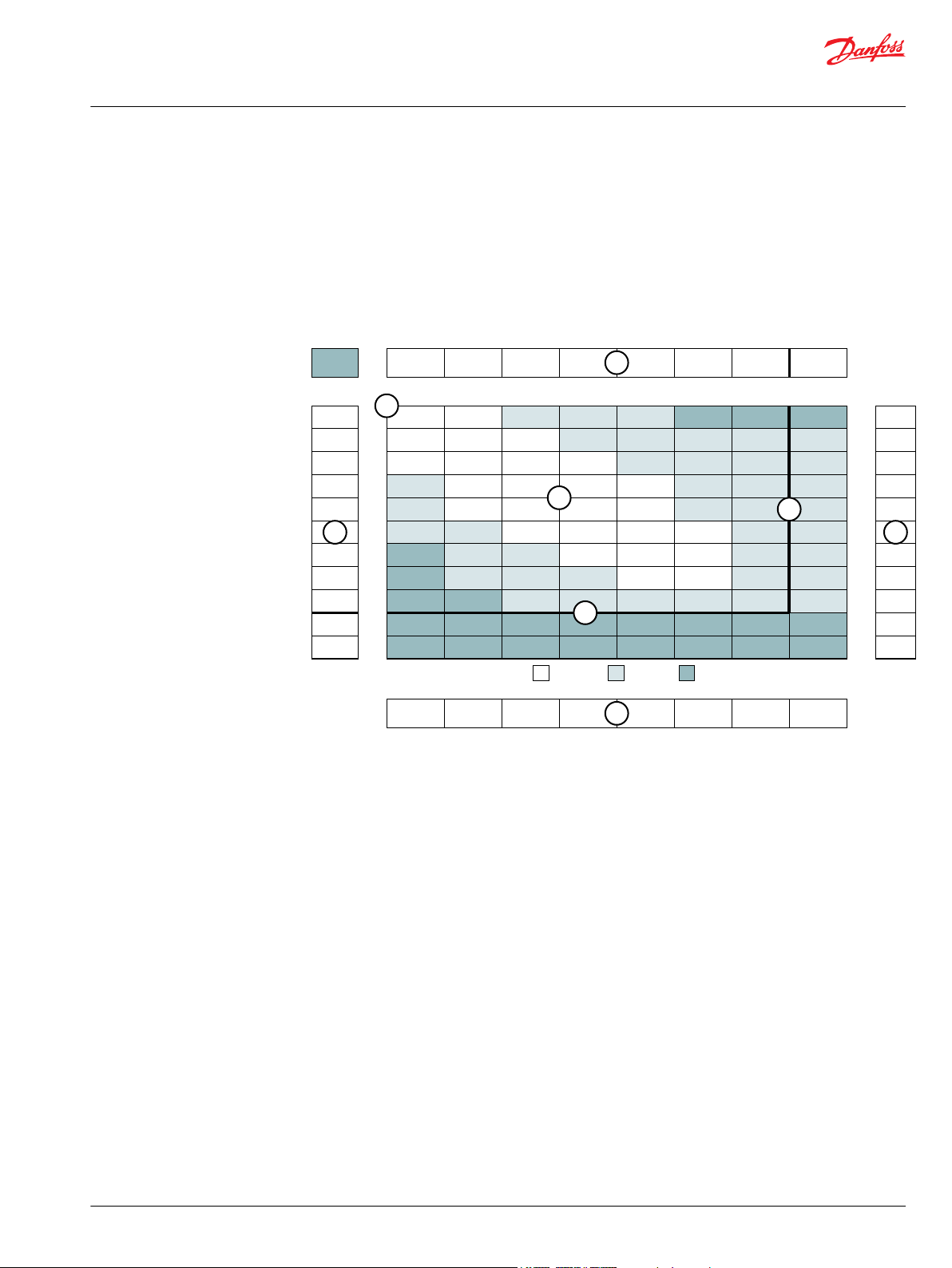
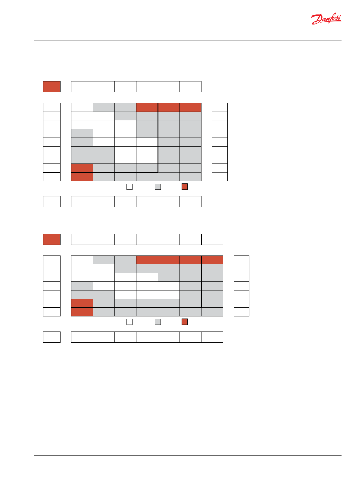
Product Testing
Performance testing is the critical measure of a motor’s ability to convert flow and pressure into speed
and torque. All product testing is conducted using Danfoss’ state of the art test facility. This facility utilizes
fully automated test equipment and custom designed software to provide accurate, reliable test data.
Test routines are standardized, including test stand calibration and stabilization of fluid temperature and
viscosity, to provide consistent data. The example below provides an explanation of the values pertaining
to each heading on the performance chart.
1. Flow represents the amount of fluid passing through
the motor during each minute of the test.
2. Pressure refers to the measured pressure differential
between the inlet and return ports of the motor during
the test.
3. The maximum continuous pressure rating and
Allowable Bearing and Shaft Loading
maximum intermittent pressure rating of the motor are
separated by the dark lines on the chart.
5. The maximum continuous flow rating and maximum
intermittent flow rating of the motor are separated by the
dark line on the chart.
7. Areas within the white shading represent maximum
motor efficiencies.
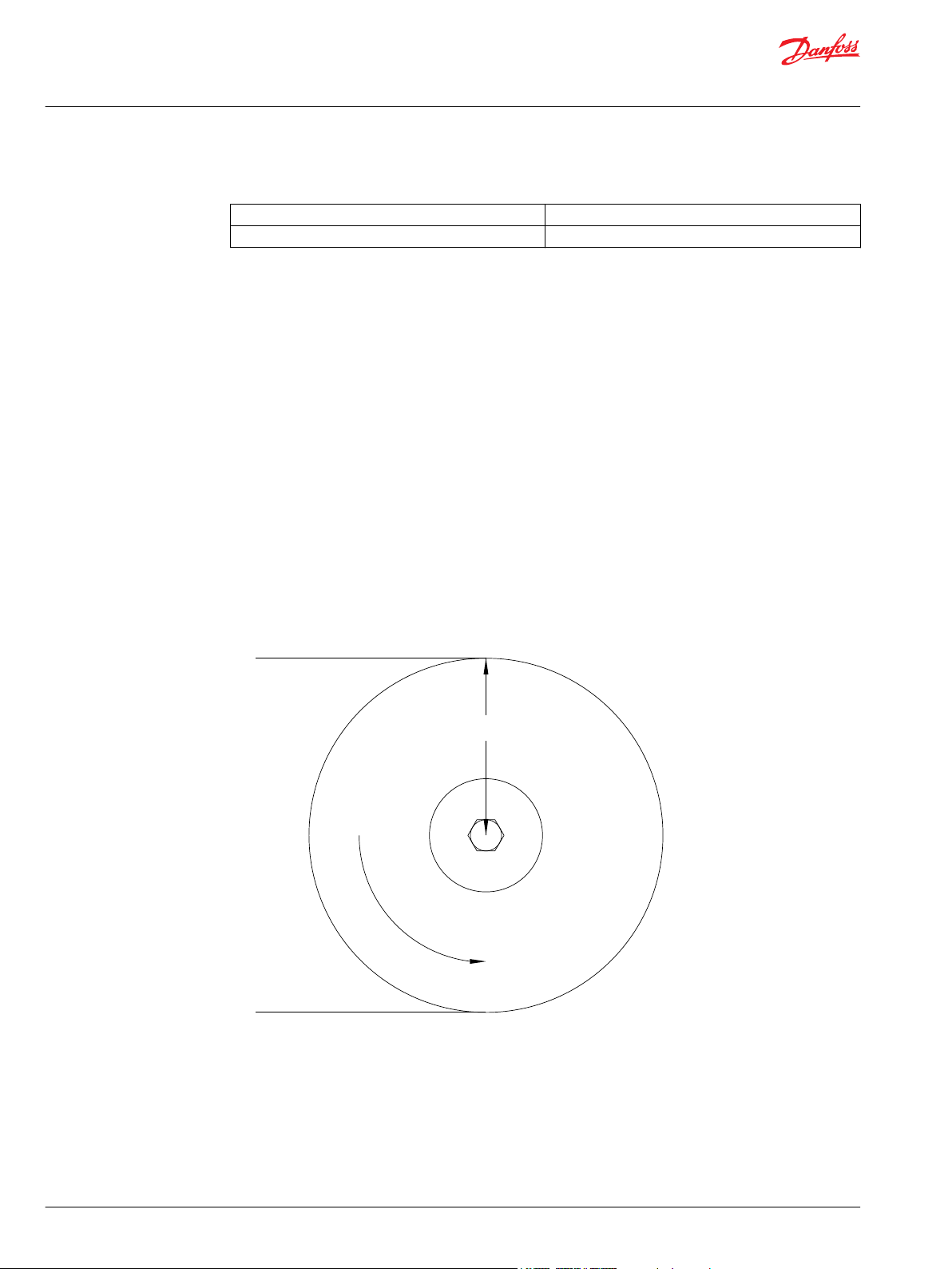
This catalog provides curves showing allowable radial loads at points along the longitudinal axis of the
motor. They are dimensioned from the mounting flange. Two capacity curves for the shaft and bearings
are shown. A vertical line through the centerline of the load drawn to intersect the x-axis intersects the
©
Danfoss | December 2019 BC267362166283en-000201 | 7
curves at the load capacity of the shaft and of the bearing.
4. Theoretical RPM represents the RPM that the motor
would produce if it were 100% volumetrically efficient.
Measured RPM divided by the theoretical RPM give the
actual volumetric efficiency of the motor.
6. Performance numbers represent the actual torque and
speed generated by the motor based on the
corresponding input pressure and flow. The numbers on
the top row indicate torque as measured in Nm [lb-in],
while the bottom number represents the speed of the
output shaft.
8. Theoretical Torque represents the torque that the
motor would produce if it were 100% mechanically
efficient. Actual torque divided by the theoretical torque
gives the actual mechanical efficiency of the motor.
Page 8
9000
8000
7000
6000
5000
4000
3000
2000
1000
lb
4000
3500
3000
2500
2000
1500
1000
500
daN
445 daN [1000 lb]
445 daN [1000 lb]
BEARING
SHAFT
-100
-50 -25 0 25 50 75 100
mm
-75
-100
-50 -25 0 25 50 75 100
mm
-75
P109320
Technical Information
Orbital Motors Type WD, WP and WR
Technical Information
In the example below, the maximum radial load bearing rating is between the internal roller bearings
illustrated with a solid line. The allowable shaft rating is shown with a dotted line.
The bearing curves for each model are based on laboratory analysis and testing conducted at Danfoss.
The shaft loading is based on a 3:1 safety factor and 330 Kpsi tensile strength. The allowable load is the
lower of the curves at a given point. For instance, one inch in front of the mounting flange the bearing
capacity is lower than the shaft capacity. In this case, the bearing is the limiting load. The motor user
needs to determine which series of motor to use based on their application knowledge.
ISO 281 Ratings vs. Manufacturer's Ratings
Published bearing curves can come from more than one type of analysis. The ISO 281 bearing rating is an
international standard for the dynamic load rating of roller bearings. The rating is for a set load at a speed
of 33 1/3 RPM for 500 hours (1 million revolutions). The standard was established to allow consistent
comparisons of similar bearings between manufacturers. The ISO 281 bearing ratings are based solely on
the physical characteristics of the bearings, removing any manufacturers specific safety factors or
empirical data that influences the ratings.
Manufacturers’ ratings are adjusted by diverse and systematic laboratory investigations, checked
constantly with feedback from practical experience. Factors taken into account that affect bearing life are
material, lubrication, cleanliness of the lubrication, speed, temperature, magnitude of the load and the
bearing type.
The operating life of a bearing is the actual life achieved by the bearing and can be significantly different
from the calculated life. Comparison with similar applications is the most accurate method for bearing life
estimations.
8 | © Danfoss | December 2019 BC267362166283en-000201
Example Load Rating for Mechanically Retained Needle Roller Bearings
Bearing Life L
L
10
C dynamic load rating
10
(C/P)p [106 revolutions]
nominal rating life
Page 9

Technical Information
Orbital Motors Type WD, WP and WR
Technical Information
P equivalent dynamic load
Life Exponent p 10/3 for needle bearings
Bearing Load Multiplication Factor Table
RPM Factor
50 1.23
100 1.00
200 0.81
300 0.72
400 0.66
500 0.62
600 0.58
700 0.56
800 0.50
Vehicle Drive Calculations
When selecting a wheel drive motor for a mobile vehicle, a number of factors concerning the vehicle
must be taken into consideration to determine the required maximum motor RPM, the maximum torque
required and the maximum load each motor must support. The following sections contain the necessary
equations to determine this criteria. An example is provided to illustrate the process.
Sample application (vehicle design criteria)
vehicle description 4 wheel vehicle
vehicle drive 2 wheel drive
GVW 1,500 lbs.
weight over each drive wheel 425 lbs.
rolling radius of tires 16 in.
desired acceleration 0-5 mph in 10 sec.
top speed 5 mph
gradability 20%
worst working surface poor asphalt
To determine maximum motor speed
RPM = (2.65 x KPH x G) / rm or RPM = (168 x MPH x G) / ri
KPH max. vehicle speed (kilometers/hr)
MPH max. vehicle speed (miles/hr)
G gear reduction ratio (if none, G = 1)
rm rolling radius of tire (meters)
ri rolling radius of tire (inches)
RPM = (168 x 5 x 1) / 16 = 52.5
©
Danfoss | December 2019 BC267362166283en-000201 | 9
Page 10

Technical Information
Orbital Motors Type WD, WP and WR
Technical Information
To determine maximum torque requirement of motor
To choose a motor(s) capable of producing enough torque to propel the vehicle, it is necessary to
determine the Total Tractive Effort (TE) requirement for the vehicle. To determine the total tractive effort,
the following equation must be used:
TE = RR + GR + FA + DP (lbs or N)
TE Total tractive effort
RR Force necessary to overcome rolling resistance
GR Force required to climb a grade
FA Force required to accelerate
DP Drawbar pull required
The components for this equation may be determined using the following steps.
Step One: Determine Rolling Resistance
Rolling Resistance (RR) is the force necessary to propel a vehicle over a particular surface. It is
recommended that the worst possible surface type to be encountered by the vehicle be factored into the
equation.
RR = (GVW / 1000) x R (lb or N)
GVW gross (loaded) vehicle weight (lb or kg)
R surface friction (value from Rolling Resistance on page 10)
Rolling Resistance
Concrete (excellent) 10
Concrete (good) 15
Concrete (poor) 20
Asphalt (good) 12
Asphalt (fair) 17
Asphalt (poor) 22
Macadam (good) 15
Macadam (fair) 22
Macadam (poor) 37
Cobbles (ordinary) 55
Cobbles (poor) 37
Snow (2 inch) 25
Snow (4 inch) 37
Dirt (smooth) 25
Dirt (sandy) 37
Mud 37 to 150
Sand (soft) 60 to 150
Sand (dune) 160 to 300
Step Two: Determine Grade Resistance
Grade Resistance (GR) is the amount of force necessary to move a vehicle up a hill or “grade.” This
calculation must be made using the maximum grade the vehicle will be expected to climb in normal
operation.
10 | © Danfoss | December 2019 BC267362166283en-000201
Page 11

Technical Information
Orbital Motors Type WD, WP and WR
Technical Information
To convert incline degrees to % Grade:
% Grade = [tan of angle (degrees)] x 100
GR = (% Grade / 100) x GVW (lb or N)
Example: GR = (20 / 100) x 1500 lbs = 300 lbs
Step Three: Determine Acceleration Force
Acceleration Force (FA) is the force necessary to accelerate from a stop to maximum speed in a desired
time.
FA = (KPH x GVW (N)) / (35.32 x t) or FA = (MPH x GVW (lb)) / (22 x t)
t time to maximum speed (seconds)
Example: FA = (5 x 1500 lbs) / (22 x 10) = 34 lbs
Step Four: Determine Drawbar Pull
Drawbar Pull (DP) is the additional force, if any, the vehicle will be required to generate if it is to be used
to tow other equipment. If additional towing capacity is required for the equipment, repeat steps one
through three for the towable equipment and sum the totals to determine DP.
Step Five: Determine Total Tractive Effort
The Tractive Effort (TE) is the sum of the forces calculated in steps one through three above. On low
speed vehicles, wind resistance can typically be neglected. However, friction in drive components may
warrant the addition of 10% to the total tractive effort to insure acceptable vehicle performance.
TE = RR + GR + FA + DP (lb or N)
Example: TE = 33 + 300 + 34 + 0 (lbs) = 367 lbs
Step Six: Determine Motor Torque
The Motor Torque (T) required per motor is the Total Tractive Effort divided by the number of motors
used on the machine. Gear reduction is also factored into account in this equation.
T = (TE x rm) / (M x G) Nm per motor or T = (TE x ri) / (M x G) lb-in per motor
M number of driving motors
Example: T = (367 x 16) / (2 x 1) lb-in/motor = 2936 lb-in
Step Seven: Determine Wheel Slip
To verify that the vehicle will perform as designed in regards to tractive effort and acceleration, it is
necessary to calculate wheel slip (TS) for the vehicle. In special cases, wheel slip may actually be desirable
to prevent hydraulic system overheating and component breakage should the vehicle become stalled.
TS = (W x f x rm) / G (Nm per motor) or TS = (W x f x ri) / G (lb-in per motor)
f coefficient of friction (see Coefficient of friction (f) on page 11)
W loaded vehicle weight over driven wheel (lb or N)
Example: TS = (425 x .06 x 16) / 1 = lb-in/motor = 4080 lbs
Coefficient of friction (f)
Steel on steel 0.3
Rubber tire on dirt 0.5
©
Danfoss | December 2019 BC267362166283en-000201 | 11
Page 12
Radius 76 mm [3.00 in]
Torque
1129 Nm
[10000 lb-in]
P109321
Technical Information
Orbital Motors Type WD, WP and WR
Technical Information
Coefficient of friction (f) (continued)
Rubber tire on a hard surface 0.6 - 0.8
Rubber tire on cement 0.7
To determine radial load capacity requirement of motor
When a motor used to drive a vehicle has the wheel or hub attached directly to the motor shaft, it is
critical that the radial load capabilities of the motor are sufficient to support the vehicle. After calculating
the Total Radial Load (RL) acting on the motors, the result must be compared to the bearing/shaft load
charts for the chosen motor to determine if the motor will provide acceptable load capacity and life.
RL = sqrt(W2 + (T / ri)2) lb or RL = sqrt(W2 + (T / rm)2) kg
Example: RL = sqrt(4252 + (2936 / 16)2) = 463 lbs
Once the maximum motor RPM, maximum torque requirement, and the maximum load each motor must
support have been determined, these figures may then be compared to the motor performance charts
and to the bearing load curves to choose a series and displacement to fulfill the motor requirements for
the application.
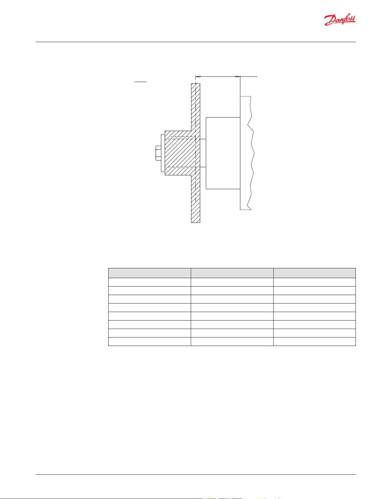
Induced Side Load
In many cases, pulleys or sprockets may be used to transmit the torque produced by the motor. Use of
these components will create a torque induced side load on the motor shaft and bearings. It is important
that this load be taken into consideration when choosing a motor with sufficient bearing and shaft
capacity for the application.
To determine the side load, the motor torque and pulley or sprocket radius must be known. Side load
may be calculated using the formula below. The distance from the pulley/sprocket centerline to the
mounting flange of the motor must also be determined. These two figures may then be compared to the
bearing and shaft load curve of the desired motor to determine if the side load falls within acceptable
load ranges.
12 | © Danfoss | December 2019 BC267362166283en-000201
Page 13
Distance
Side Load =
Side Load = 14855 Nm [3333 lbs]
Torque
Radius
P109322
Technical Information
Orbital Motors Type WD, WP and WR
Technical Information
Hydraulic Equations
Multiplication Factor Abbreviation Prefix
12
10
10
10
10
10
10
10
10
9
6
3
2
1
-1
-2
T tera
G giga
M mega
K kilo
h hecto
da deka
d deci
c centi
Theo. Speed (RPM) (1000 x LPM) / Displacement (cm3/rev)
(231 x GPM) / Displacement (in3/rev)
Theo. Torque (lb-in) (Bar x Disp. (cm3/rev)) / 20 pi
(PSI x Disp. (in3/rev) / 6.28
Power In (HP) (Bar x LPM) / 600
(PSI x GPM) / 1714
Power Out (HP) (Torque (Nm) x RPM) / 9543
(Torque (lb-in) x RPM) / 63024
©
Danfoss | December 2019 BC267362166283en-000201 | 13
Page 14
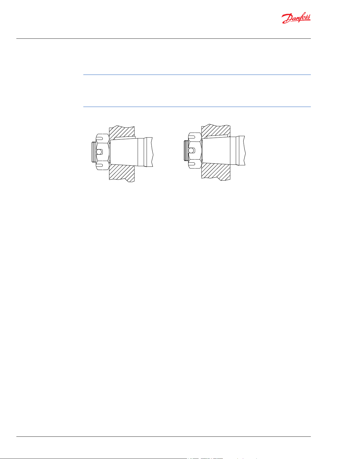
Incorrect
Correct
P109323
Technical Information
Orbital Motors Type WD, WP and WR
Technical Information
Shaft Nut Information
The tightening torques listed with each nut should only be used as a guideline. Hubs may require higher
or lower tightening torque depending on the material. Consult the hub manufacturer to obtain
recommended tightening torque. To maximize torque transfer from the shaft to the hub, and to
minimize the potential for shaft breakage, a hub with sufficient thickness must fully engage the taper
length of the shaft.
Hub engagement
14 | © Danfoss | December 2019 BC267362166283en-000201
Page 15
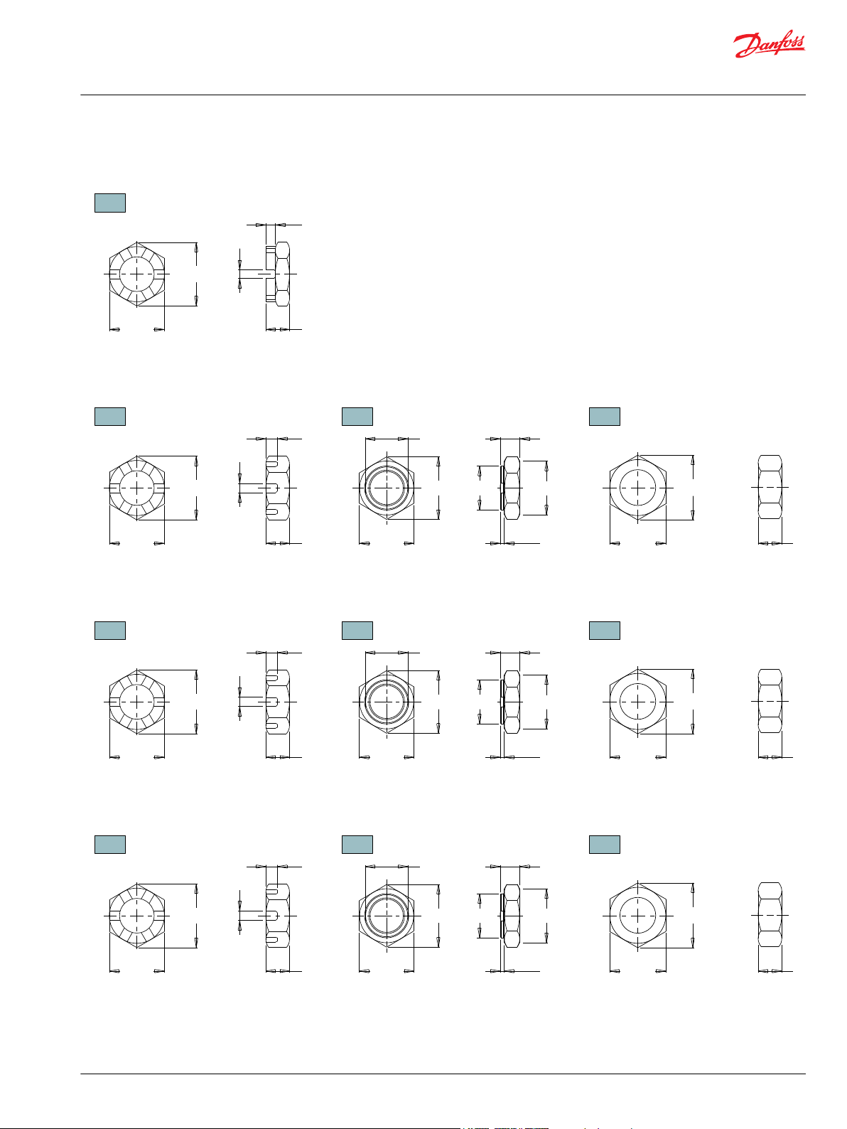
A Slotted Nut
35MM TAPERED SHAFTS
B Lock Nut
B Lock Nut
B
Lock Nut
C
Solid Nut
C
Solid Nut
C Solid Nut
M24 x 1.5 Thread
A
Slotted Nut
1” TAPERED SHAFTS
3/4-28 Thread
A Slotted Nut
1-1/4” TAPERED SHAFTS
1-20 Thread
A Slotted Nut
1-3/8” & 1-1/2” TAPERED SHAFTS
1 1/8-18 Thread
33 [1.29]
5 [.19]
6 [.24]
12 [.48]
Torque Specifications: 20 - 23 daNm [150 - 170 ft.lb.]
29 [1.13]28 [1.12]
42 [1.64]
6 [.22]
6 [.24]
15 [.59]
Torque Specifications: 32.5 daNm [240 ft.lb.]
36 [1.42]
16 [.63]
3.5 [.14]
33 [1.29]
28 [1.11]
12 [.47]
33 [1.28]
23 [.92]
24 [.95]
28 [1.10]
Torque Specifications: 24 - 27 daNm [180 - 200 ft.lb.]
Torque Specifications: 20 - 23 daNm [150 - 170 ft.lb.]
44 [1.73]
5 [.19]
6 [.25]
14 [.55]
Torque Specifications: 38 daNm [280 ft.lb.] Max.
35 [1.38]38 [1.48]
16 [.63]
4 [.16]
40 [1.57]
38 [1.48]
14 [.55]
44 [1.73]
29 [1.14]
30 [1.18]
34 [1.34]
Torque Specifications: 33 - 42 daNm [240 - 310 ft.lb.] Torque Specifications: 38 daNm [280 ft.lb.] Max.
48 [1.90]
5 [.19]
6 [.22]
15 [.61]
Torque Specifications: 41 - 54 daNm [300 - 400 ft.lb.]
44 [1.73]42 [1.66]
16 [.63]
4 [.16]
51 [2.00]
42 [1.66]
15 [.61]
48 [1.90]
35 [1.38]
36 [1.42]
44 [1.73]
Torque Specifications: 34 - 48 daNm [250 - 350 ft.lb.]
Torque Specifications: 41 - 54 daNm [300 - 400 ft.lb.]
P109324
Technical Information
Orbital Motors Type WD, WP and WR
Technical Information
©
Danfoss | December 2019 BC267362166283en-000201 | 15
Page 16
P109325
Technical Information
Orbital Motors Type WD, WP and WR
Optional Motor Features
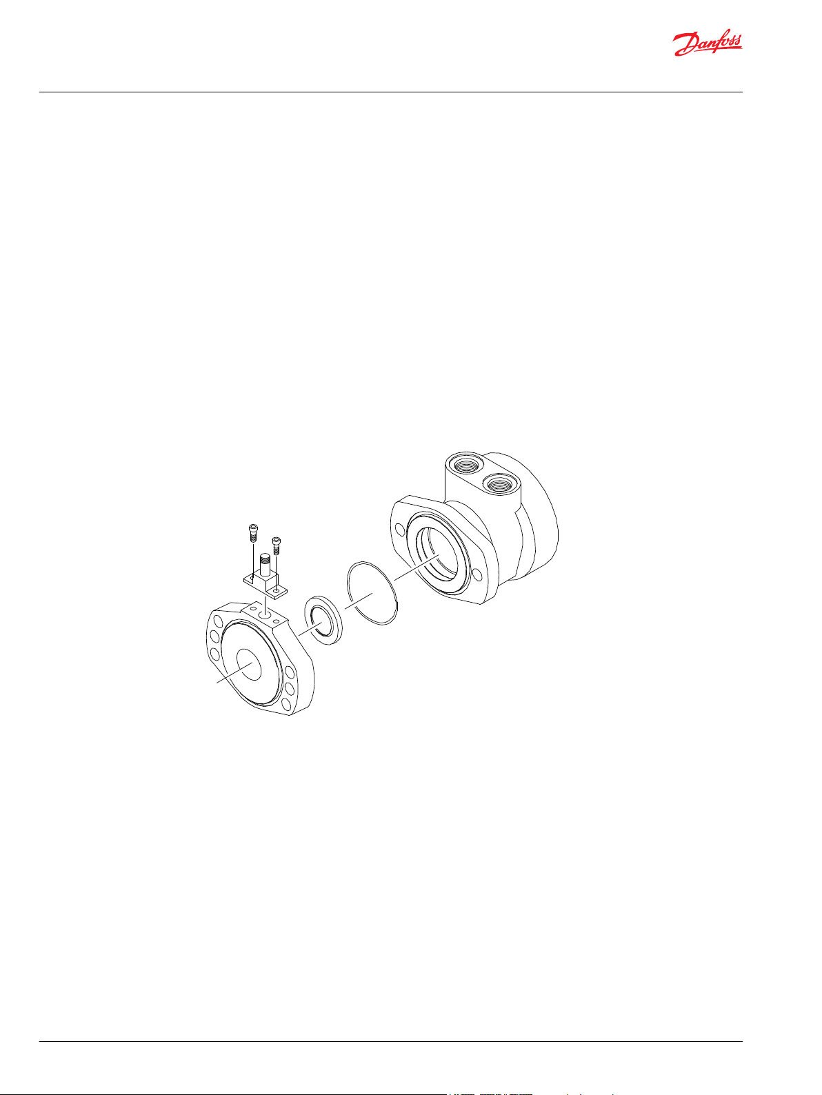
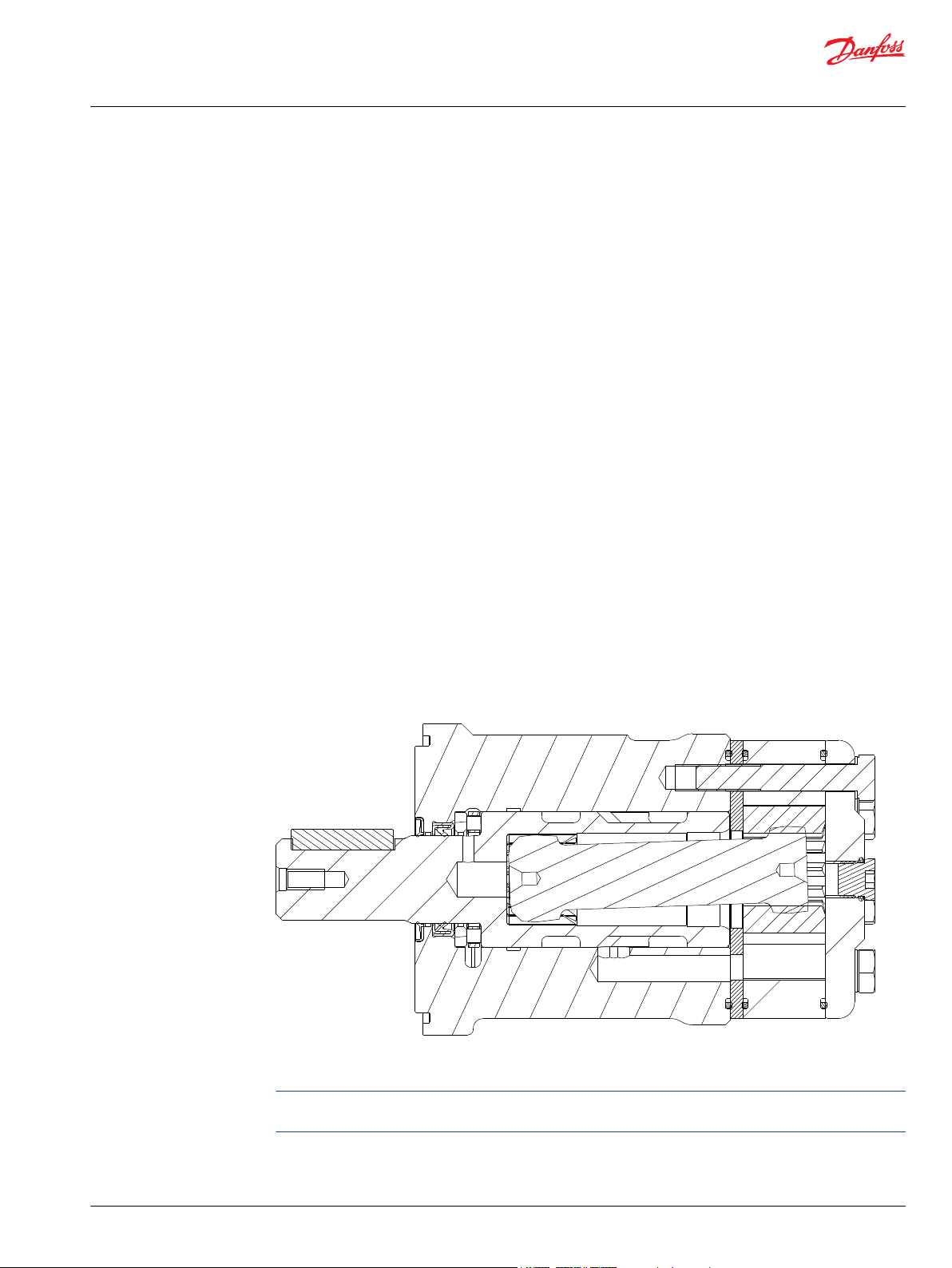
Speed Sensor Options
Danfoss offers both single and dual element speed sensor options providing a number of benefits to
users by incorporating the latest advancements in sensing technology and materials. The 700 & 800
series motors single element sensors provide 60 pulses per revolution with the dual element providing
120 pulses per revolution, with all other series providing 50 & 100 pulses respectively. Higher resolution is
especially beneficial for slow speed applications, where more information is needed for smooth and
accurate control. The dual sensor option also provides a direction signal allowing end-users to monitor
the direction of shaft rotation .
Unlike competitive designs that breach the high pressure area of the motor to add the sensor, the
Danfoss speed sensor option utilizes an add-on flange to locate all sensor components outside the high
pressure operating environment. This eliminates the potential leak point common to competitive
designs. Many improvements were made to the sensor flange including changing the material from cast
iron to acetal resin, incorporating a Buna-N shaft seal internal to the flange, and providing a grease zerk,
which allows the user to fill the sensor cavity with grease. These improvements enable the flange to
withstand the rigors of harsh environments.
Another important feature of the new sensor flange is that it is self-centering, which allows it to remain
concentric to the magnet rotor. This produces a consistent mounting location for the new sensor
module, eliminating the need to adjust the air gap between the sensor and magnet rotor. The oring
sealed sensor module attaches to the sensor flange with two small screws, allowing the sensor to be
serviced or upgraded in the field in under one minute. This feature is especially valuable for mobile
applications where machine downtime is costly. The sensor may also be serviced without exposing the
hydraulic circuit to the atmosphere. Another advantage of the self-centering flange is that it allows users
to rotate the sensor to a location best suited to their application. This feature is not available on
competitive designs, which fix the sensor in one location in relationship to the motor mounting flange.
Features / Benefits
•
Grease fitting allows sensor cavity to be filled with grease for additional protection.
•
Internal extruder seal protects against environmental elements.
•
M12 or weatherpack connectors provide installation flexibility.
•
Dual element sensor provides up to 120 pulses per revolution and directional sensing.
•
Modular sensor allows quick and easy servicing.
16 | © Danfoss | December 2019 BC267362166283en-000201
Page 17
1
2
3
4
P109326
Technical Information
Orbital Motors Type WD, WP and WR
Optional Motor Features
•
Acetal resin flange is resistant to moisture, chemicals, oils, solvents and greases.
•
Self-centering design eliminates need to set magnetto-sensor air gap.
•
Protection circuitry
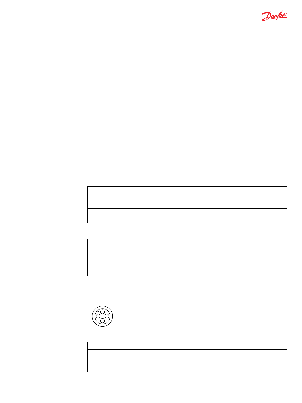
Sensor Options
•
Z - 4-pin M12 male connector
This option has 50 pulses per revolution on all series except the DT which has 60 pulses per
revolution. This option will not detect direction.
•
Y - 3-pin male weatherpack connector
This option has 50 pulses per revolution on all series except the DT which has 60 pulses per
revolution. This option will not detect direction. Includes a 610 mm [2 ft] cable.
•
X - 4-pin M12 male connector
This option has 100 pulses per revolution on all series except the DT which has 120 pulses per
revolution. This option will detect direction.
•
W - 4-pin male weatherpack connector
This option has 100 pulses per revolution on all series except the DT which has 120 pulses per
revolution. This option will detect direction. Includes a 610 mm [2 ft] cable.
Single Element Sensor - Y & Z
Supply voltages 7.5-24 Vdc
Maximum output off voltage 24 V
Maximum continuous output current < 25 ma
Signal levels (low, high) 0.8 to supply voltage
Operating Temp -30°C to 83°C [-22°F to 181°F]
Dual Element Sensor - X & W
Supply voltages 7.5-18 Vdc
Maximum output off voltage 18 V
Maximum continuous output current < 20 ma
Signal levels (low, high) 0.8 to supply voltage
Operating Temp -30°C to 83°C [-22°F to 181°F]
Sensor Connectors
Z Option
Pin 1 positive brown or red
Pin 2 n/a white
Pin 3 negative blue
Pin 4 pulse out black
©
Danfoss | December 2019 BC267362166283en-000201 | 17
Page 18
1
2
3
4
P109327
C B A
P109328
CD B A
P109329
Technical Information
Orbital Motors Type WD, WP and WR
Optional Motor Features
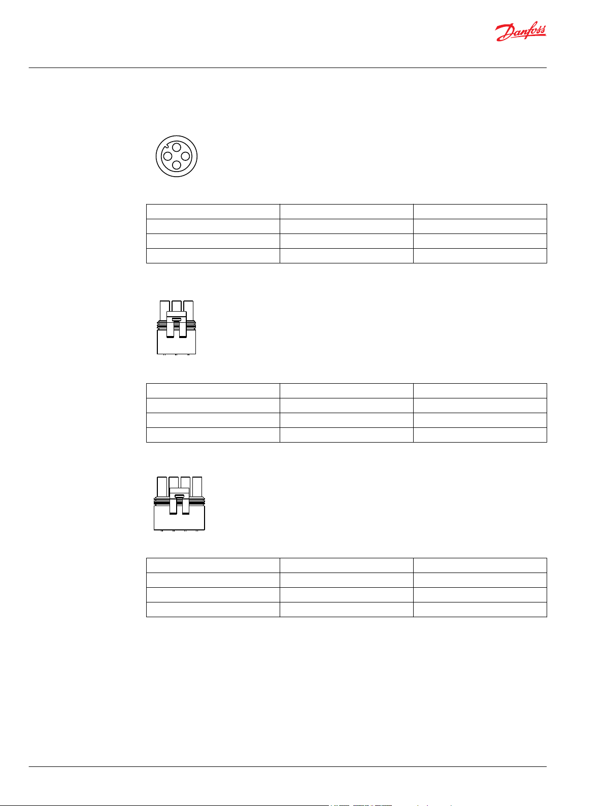
X Option
Pin 1 positive brown or red
Pin 2 direction out white
Pin 3 negative blue
Pin 4 pulse out black
Y Option
Pin A positive brown or red
Pin B negative blue
Pin C pulse out black
Pin D n/a white
W Option
Pin A positive brown or red
Pin B negative blue
Pin C pulse out black
Pin D direction out white
Protection Circuitry
The single element sensor has been improved and incorporates protection circuitry to avoid electrical
damage caused by:
•
reverse battery protection
•
overvoltage due to power supply spikes and surges (60 Vdc max.)
•
power applied to the output lead
The protection circuit feature will help “save” the sensor from damage mentioned above caused by:
18 | © Danfoss | December 2019 BC267362166283en-000201
Page 19
P109330
Technical Information
Orbital Motors Type WD, WP and WR
Optional Motor Features
•
faulty installation wiring or system repair
•
wiring harness shorts/opens due to equipment failure or harness damage resulting from accidental
conditions (i.e. severed or grounded wire, ice, etc.)
•
power supply spikes and surges caused by other electrical/electronic components that may be
intermittent or damaged and “loading down” the system.
While no protection circuit can guarantee against any and all fault conditions. The single element sensor
from Danfoss with protection circuitry is designed to handle potential hazards commonly seen in real
world applications.
Unprotected versions are also available for operation at lower voltages down to 4.5V.
Freeturning Rotor Option
The ‘AC’ option or “Free turning” option refers to a specially prepared rotor assembly. This rotor assembly
has increased clearance between the rotor tips and rollers allowing it to turn more freely than a standard
rotor assembly. For spool valve motors, additional clearance is also provided between the shaft and
housing bore. The ‘AC’ option is available for all motor series and displacements.
There are several applications and duty cycle conditions where ‘AC’ option performance characteristics
can be beneficial. In continuous duty applications that require high flow/high rpm operation, the benefits
are twofold. The additional clearance helps to minimize internal pressure drop at high flows. This
clearance also provides a thicker oil film at metal to metal contact areas and can help extend the life of
the motor in high rpm or even over speed conditions. The ‘AC’ option should be considered for
applications that require continuous operation above 57 LPM [15 GPM] and/ or 300 rpm. Applications
that are subject to pressure spikes due to frequent reversals or shock loads can also benefit by specifying
the ‘AC’ option. The additional clearance serves to act as a buffer against spikes, allowing them to be
bypassed through the motor rather than being absorbed and transmitted through the drive link to the
output shaft. The trade-off for achieving these benefits is a slight loss of volumetric efficiency at high
pressures.
Valve Cavity Option
The valve cavity option provides a cost effective way to incorporate a variety of cartridge valves integral
to the motor. The valve cavity is a standard 10 series (12 series on the 800 series motor) 2-way cavity that
accepts numerous cartridge valves, including overrunning check valves, relief cartridges, flow control
valves, pilot operated check fuses, and high pressure shuttle valves. Installation of a relief cartridge into
the cavity provides an extra margin of safety for applications encountering frequent pressure spikes.
Relief cartridges from 69 to 207 bar [1000 to 3000 psi] may also be factory installed.
©
Danfoss | December 2019 BC267362166283en-000201 | 19
Page 20
P109331
Technical Information
Orbital Motors Type WD, WP and WR
Optional Motor Features
For basic systems with fixed displacement pumps, either manual or motorized flow control valves may be
installed into the valve cavity to provide a simple method for controlling motor speed. It is also possible
to incorporate the speed sensor option and a programmable logic controller with a motorized flow
control valve to create a closed loop, fully automated speed control system. For motors with internal
brakes, a shuttle valve cartridge may be installed into the cavity to provide a simple, fully integrated
method for supplying release pressure to the pilot line to actuate an integral brake. To discuss other
alternatives for the valve cavity option, contact an authorized Danfoss distributor.
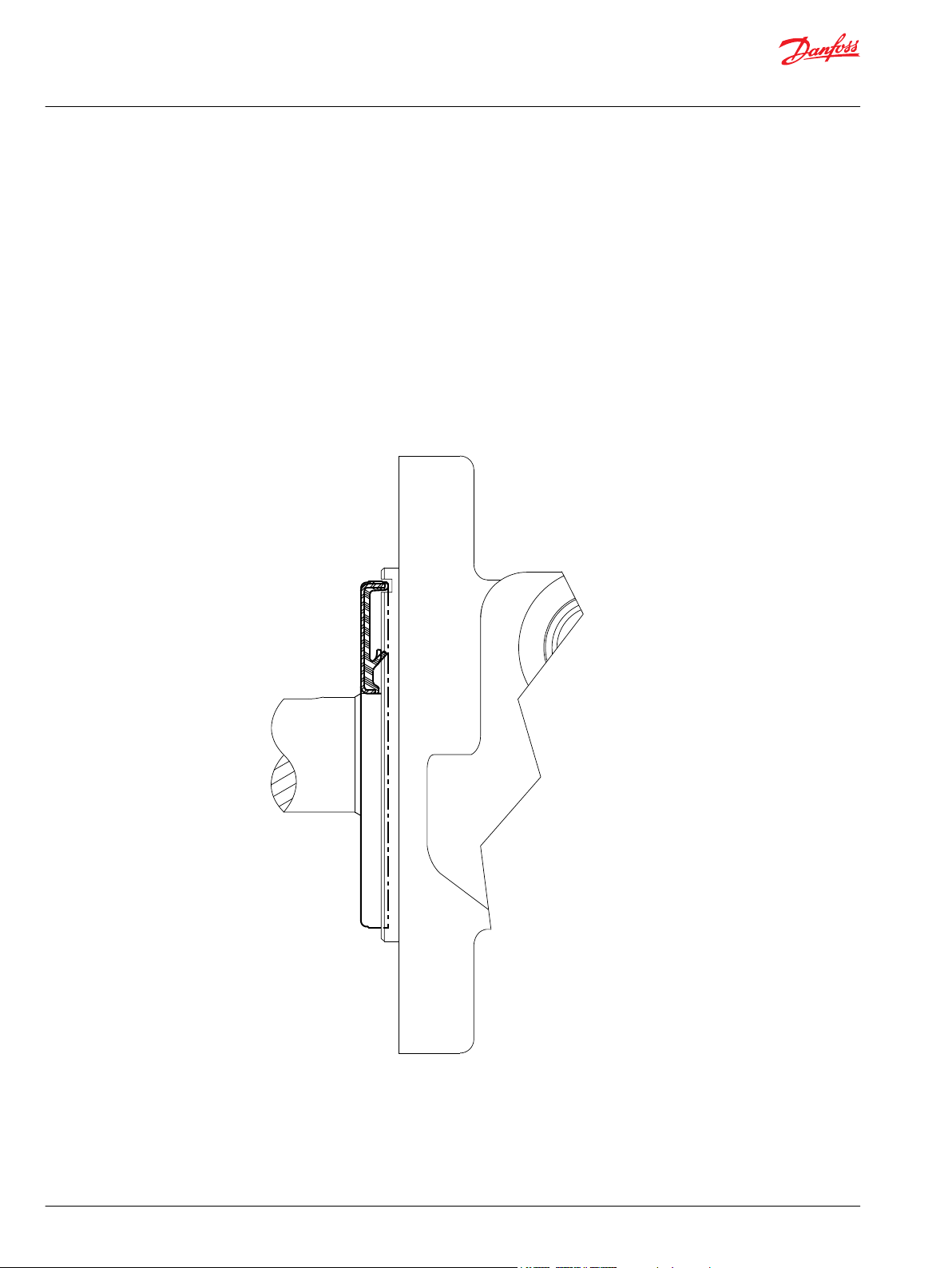
Slinger Seal Option
Slinger seals are available on select series offered by Danfoss. Slinger seals offer extendes shaft/shaft seal
protection by prevented a buildup of material around the circumference of the shaft which can lead to
premature shaft seal failures. The Danfoss slinger seals are designed to be larger in diameter than
competitive products, providing greater surface speed and ‘slinging action’.
Slinger seals are also available on 4-hole flange mounts on select series. Contact a Danfoss Customer
Service Representative for additional information.
20 | © Danfoss | December 2019 BC267362166283en-000201
Page 21
P109594
Technical Information
Orbital Motors Type WD, WP and WR
WD Product Line
WD Introduction
Overview
The WD motor series is an economical solution for light duty applications requiring high torque. It has a
smaller outline yet still provides high efficiency across a wide performance range. Its integral check valves
and a provision for a case drain reduce pressure on internal seals to improve product life. The compact
package is suitable for industrial and mobile applications including car wash brushes, food processing
equipment, conveyors, machine tools, agricultural equipment, sweepers, skid steer attachments, and
more.
Features / Benefits
•
Built-in check valves offer versatility and increased seal life.
•
A variety of mounts and shafts provide flexibility in application design.
•
Spool valve design gives superior performance and smooth operation over a wide speed and torque
range.
•
Integral rotor design provides smooth performance, compact volume and low weight.
•
Low port profiling is suitable for applications with limited space.
Typical Applications
agriculture equipment, conveyors, carwashes, sweepers, food processing, grain augers, spreaders, feed
rollers, augers, brush drives and more
Series Descriptions
145/146 - Hydraulic Motor (standard)
Specifications
Performance data is typical. Performance of production units varies slightly from one motor to another.
Running at intermittent ratings should not exceed 10% of every minute of operation.
©
Danfoss | December 2019 BC267362166283en-000201 | 21
Page 22
186
388
568
780
970
1172
1361
167
350
536
736
922
1120
1318
1502
138
316
206
688
885
1086
1285
1477
115
285
485
658
855
1046
1248
1439
106
255
447
628
830
1026
1212
1404
217
402
598
780
981
1172
1365
[80]
[80]
[71]
[71]
[62]
[53]
[44]
9
9
8
8
7
6
5
[159]
[177]
[168]
[168]
[159]
[142]
[115]
[97]
18
20
19
19
18
16
13
11
[221]
[230]
[239]
[230]
[230]
[212]
[195]
[177]
25
26
27
26
26
24
22
20
[283]
[301]
[292]
[292]
[292]
[283]
[266]
[248]
32
34
33
33
33
32
30
28
[310]
[327]
[336]
[336]
[327]
[319]
[319]
[310]
35
37
38
38
37
36
36
35
[407]
[416]
[416]
[407]
[398]
[381]
[372]
46
47
47
46
45
43
42
P109595
Torque - Nm [lb-in], Speed rpm
Flow - lpm [gpm]
30 [435] 60 [870] 80 [1160] 100 [1450] 120 [1740] 140 [2030]
Max. Inter.Max. Cont.
12 [104] 24 [208] 31 [277] 39 [347] 47 [416] 55 [485]
Theoretical Torque - Nm [lb-in]
Max.
Inter.
Max.
Cont.
025
5 [1.3]
10 [2.6]
15 [4.0]
20 [5.3]
25 [6.6]
30 [7.9]
35 [9.2]
40 [10.6]
203
407
610
813
1016
1220
1423
1626
Theoretical rpm
Overall Efficiency -
70 - 100%
40 - 69%
0 - 39%
Intermittent Ratings - 10% of Operation
Displacement tested at 45°C [113°F] with an oil viscosity of 46cSt [213 SUS]
Pressure - bar [psi]
mm [in]
Rotor
Width
4.1
[.160]
25 cm3 [1.5 in3] / rev
Technical Information
Orbital Motors Type WD, WP and WR
WD Product Line
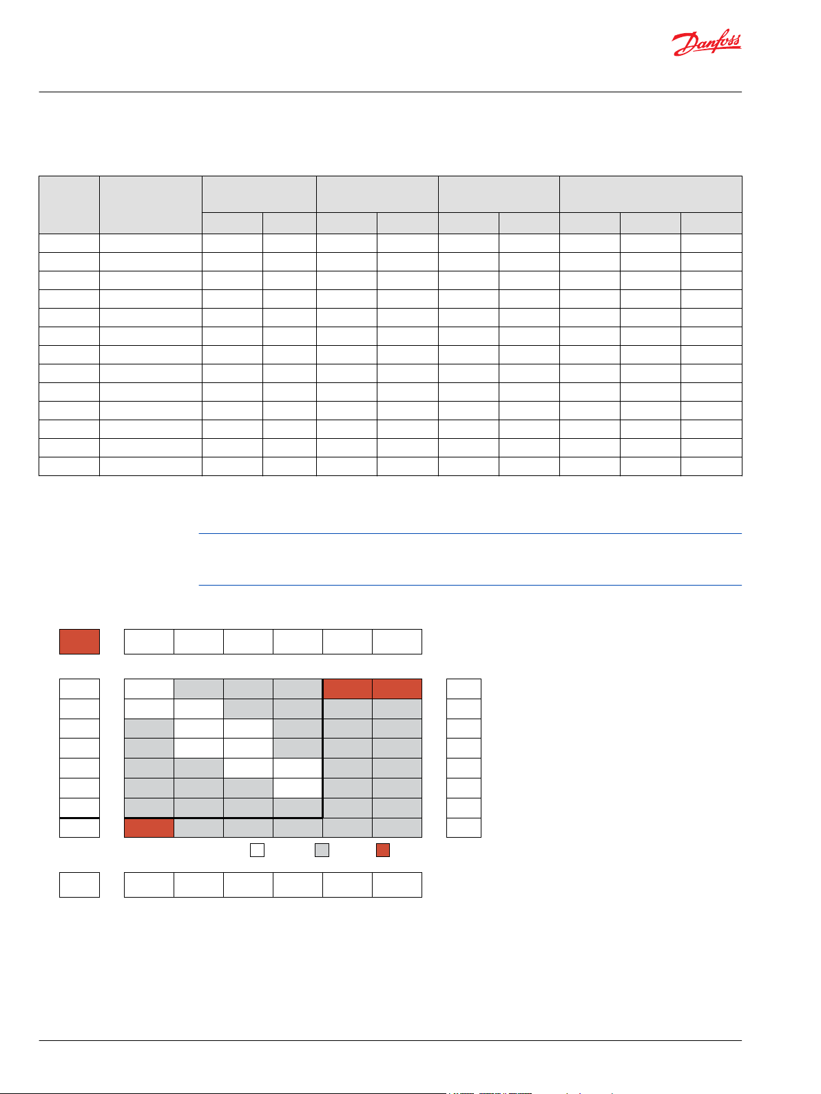
Specifications
CODE
025 24.6 [1.5] 1361 1502 35 [9] 40 [11] 34 [301] 47 [416] 100 [1450] 140 [2030] 225 [3260]
032 30.8 [1.9] 1244 1388 40 [11] 45 [12] 42 [372] 57 [505] 100 [1450] 140 [2030] 225 [3260]
040 39.7 [2.4] 1124 1312 45 [12] 53 [14] 66 [584] 79 [699] 124 [1800] 155 [2250] 225 [3260]
050 48.2 [2.9] 900 1012 45 [12] 53 [14] 91 [805] 114 [1009] 138 [2000] 173 [2500] 225 [3260]
060 59.4 [3.6] 880 970 53 [14] 60 [16] 110 [974] 136 [1204] 138 [2000] 173 [2500] 225 [3260]
080 79.6 [4.9] 752 934 60 [16] 75 [20] 141 [1248] 175 [1549] 138 [2000] 173 [2500] 225 [3260]
100 96.0 [5.9] 628 786 60 [16] 75 [20] 170 [1505] 220 [1947] 138 [2000] 173 [2500] 225 [3260]
125 122.8 [7.5] 483 604 60 [16] 75 [20] 225 [1991] 274 [2425] 138 [2000] 173 [2500] 225 [3260]
160 158.0 [9.6] 383 479 60 [16] 75 [20] 284 [2513] 345 [3054] 138 [2000] 173 [2500] 225 [3260]
200 196.5 [12.0] 308 384 60 [16] 75 [20] 312 [2761] 411 [3638] 124 [1800] 166 [2400] 225 [3260]
250 240.5 [14.7] 248 312 60 [16] 75 [20] 317 [2806] 450 [3983] 103 [1500] 155 [2250] 225 [3260]
315 303.2 [18.5] 199 250 60 [16] 75 [20] 396 [3505] 576 [5098] 103 [1500] 155 [2250] 200 [2900]
400 385.8 [23.5] 150 189 60 [16] 75 [20] 480 [4248] 582 [5151] 97 [1400] 121 [1750] 180 [2610]
Displacement
cm3 [in3]
Max. Speed
rpm
Max. Flow
lpm [gpm]
Max. Torque
Nm [lb-in]
Max. Pressure
bar [psi]
cont. inter. cont. inter. cont. inter. cont. inter. peak
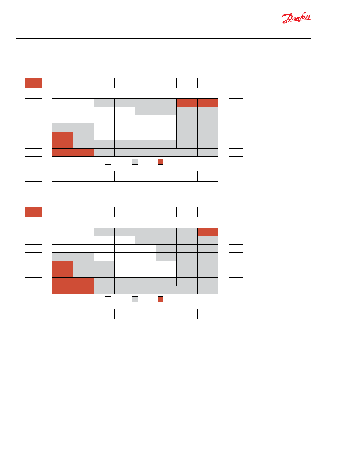
WD Functional Charts
Performance data is typical. Performance of production units varies slightly from one motor to another.
Operating at maximum continuous pressure and maximum continuous flow simultaneously is not
recommended. For additional information on product testing please refer to Product Testing on page 7.
025 Displacement Performance
22 | © Danfoss | December 2019 BC267362166283en-000201
Page 23
150
300
460
616
780
928
1090
1244
133
276
433
586
754
910
1077
1214
1388
100
253
415
566
736
882
1057
1198
1362
68
236
398
543
712
860
1035
1177
1342
203
375
520
688
824
1008
1155
1326
186
346
500
658
806
980
1130
1300
[106]
[106]
[97]
[80]
[71]
[62]
[62]
[53]
12
12
11
9
8
7
7
6
[212]
[221]
[212]
[212]
[204]
[195]
[186]
[168]
[150]
24
25
24
24
23
22
21
19
17
[283]
[292]
[292]
[283]
[283]
[274]
[274]
[257]
[248]
32
33
33
32
32
31
31
29
28
[354]
[372]
[372]
[363]
[354]
[354]
[336]
[327]
[327]
40
42
42
41
40
40
38
37
37
[425]
[434]
[434]
[425]
[416]
[407]
[407]
[398]
48
49
49
48
47
46
46
45
[487]
[504]
[496]
[496]
[496]
[487]
[478]
[478]
55
57
56
56
56
55
54
54
Torque - Nm [lb-in], Speed rpm
Flow - lpm [gpm]
30 [435] 60 [870] 80 [1160] 100 [1450] 120 [1740] 140 [2030]
Max. Inter.Max. Cont.
15 [130] 29 [260] 39 [347] 49 [434] 59 [521] 69 [608]
Theoretical Torque - Nm [lb-in]
Max.
Inter.
Max.
Cont.
032
5 [1.3]
10 [2.6]
15 [4.0]
20 [5.3]
25 [6.6]
30 [7.9]
35 [9.2]
40 [10.6]
45 [11.9]
162
325
487
649
812
974
1136
1299
1461
Theoretical rpm
Overall Efficiency -
70 - 100%
40 - 69%
0 - 39%
Intermittent Ratings - 10% of Operation
Displacement tested at 45°C [113°F] with an oil viscosity of 46cSt [213 SUS]
Pressure - bar [psi]
mm [in]
Rotor
Width
5.1
[.200]
31 cm3 [1.9 in3] / rev
P109596
182
362
548
738
932
1124
169
344
535
729
914
1102
1312
128
334
519
706
896
1084
1290
90
320
502
688
878
1062
1266
304
488
670
856
1043
1242
284
468
648
834
1014
1218
254
428
614
798
976
1168
[89]
[97]
[89]
[62]
[53]
[27]
10
11
10
7
6
3
[177]
[186]
[177]
[168]
[142]
[124]
[124]
20
21
20
19
16
14
14
[257]
[274]
[283]
[274]
[266]
[248]
[221]
29
31
32
31
30
28
25
[354]
[381]
[372]
[363]
[354]
[336]
[336]
40
43
42
41
40
38
38
[478]
[469]
[460]
[451]
[434]
[425]
54
53
52
51
49
48
[575]
[584]
[566]
[549]
[531]
[531]
65
66
64
62
60
60
[690]
[699]
[690]
[681]
[673]
[673]
78
79
78
77
76
76
Torque - Nm [lb-in], Speed rpm
Flow - lpm [gpm]
21 [300] 41 [600] 62 [900] 83 [1200] 103 [1500] 124 [1800] 155 [2250]
Max. Inter.Max. Cont.
13 [117] 26 [229] 39 [347] 52 [464] 65 [576] 78 [694] 98 [867]
Theoretical Torque - Nm [lb-in]
Max.
Inter.
Max.
Cont.
040
8 [2]
15 [4]
23 [6]
30 [8]
38 [10]
45 [12]
53 [14]
191
380
572
763
955
1144
1335
Theoretical rpm
Overall Efficiency -
70 - 100%
40 - 69%
0 - 39%
Intermittent Ratings - 10% of Operation
Displacement tested at 45°C [113°F] with an oil viscosity of 46cSt [213 SUS]
Pressure - bar [psi]
mm [in]
Rotor
Width
6.6
[.260]
40 cm3 [2.4 in3] / rev
P109597
Technical Information
Orbital Motors Type WD, WP and WR
WD Product Line
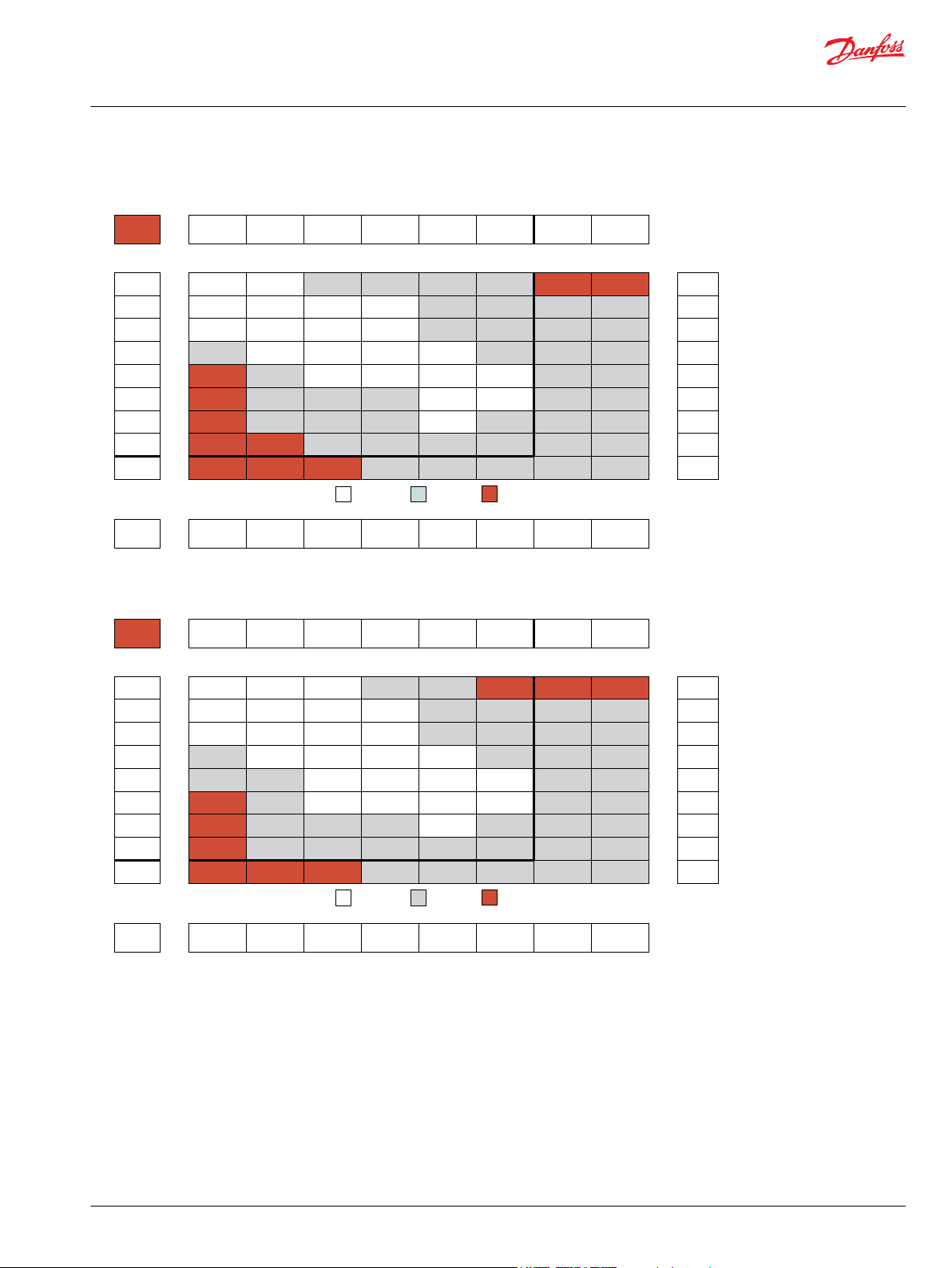
032cc Displacement Performance
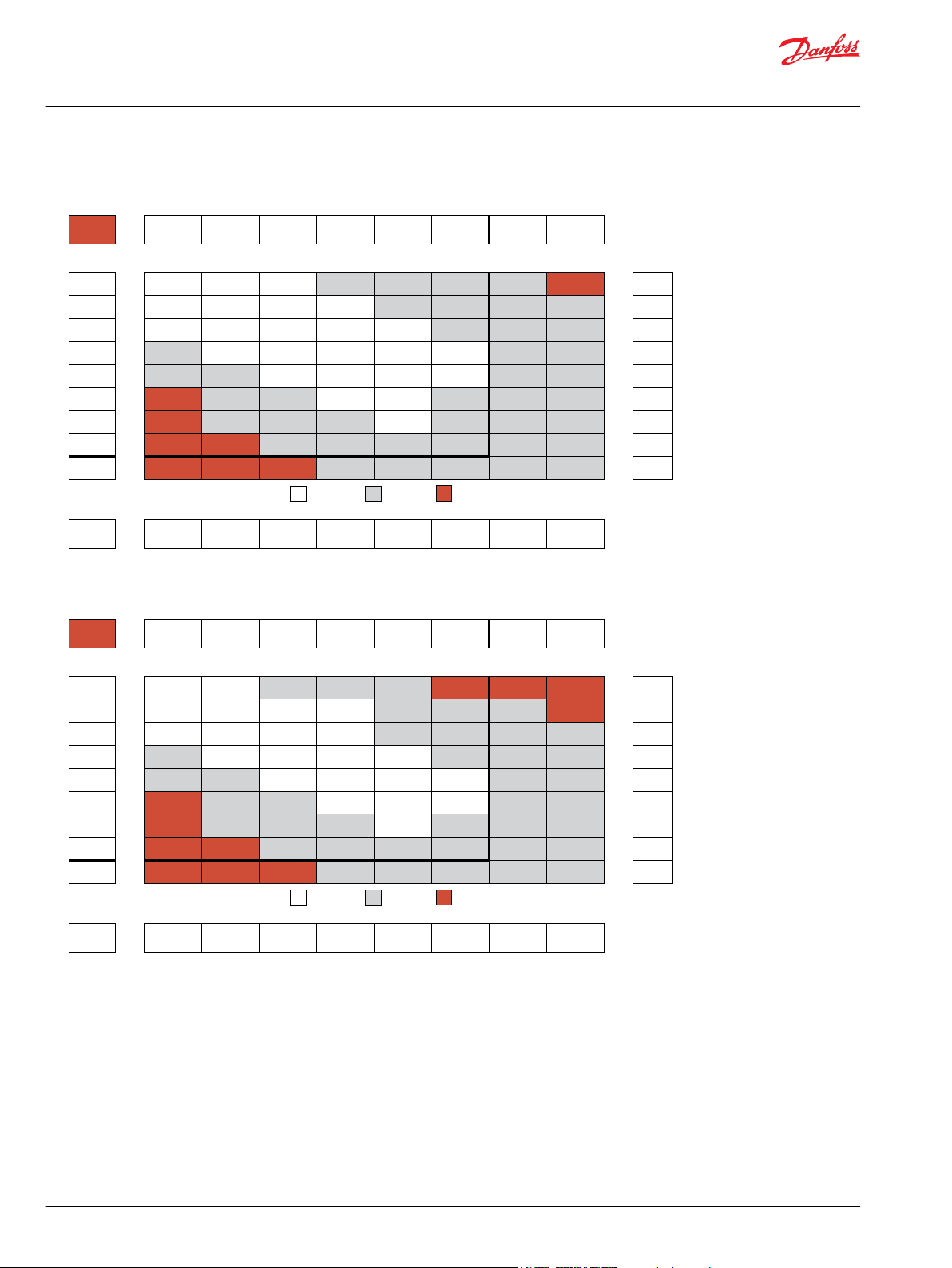
040cc Displacement Performance
©
Danfoss | December 2019 BC267362166283en-000201 | 23
Page 24
148
298
450
602
750
143
289
438
590
732
900
130
276
423
580
722
885
1012
116
260
406
555
713
875
1000
102
245
388
540
693
860
986
86
229
374
523
681
848
972
75
214
352
508
669
830
960
166
314
475
635
794
924
[124]
[124]
[106]
[80]
[18]
14
14
12
9
2
[230]
[239]
[212]
[186]
[168]
[150]
26
27
24
21
19
17
[354]
[372]
[363]
[336]
[327]
[292]
[248]
40
42
41
38
37
33
28
[354]
[381]
[372]
[363]
[354]
[336]
[336]
55
56
54
52
51
46
42
[575]
[593]
[602]
[575]
[558]
[531]
[513]
65
67
68
65
63
60
58
[726]
[735]
[743]
[717]
[681]
[646]
[620]
82
83
84
81
77
73
70
[779]
[788]
[805]
[779]
[752]
[735]
[708]
88
89
91
88
85
83
80
[1009]
[991]
[974]
[947]
[929]
[885]
114
112
110
107
105
100
Torque - Nm [lb-in], Speed rpm
Flow - lpm [gpm]
21 [300] 41 [600] 62 [900] 83 [1200] 103 [1500] 124 [1800] 138 [2000]
Max. Inter.Max. Cont.
16 [143] 31 [278] 48 [422] 64 [564] 79 [700] 95 [842] 106 [937]
173 [2500]
133 [1175]
Theoretical Torque - Nm [lb-in]
Max.
Inter.
Max.
Cont.
050
8 [2]
15 [4]
23 [6]
30 [8]
38 [10]
45 [12]
53 [14]
158
313
471
629
786
942
1100
Theoretical rpm
Overall Efficiency -
70 - 100%
40 - 69%
0 - 39%
Intermittent Ratings - 10% of Operation
Displacement tested at 45°C [113°F] with an oil viscosity of 46cSt [213 SUS]
Pressure - bar [psi]
mm [in]
Rotor
Width
6.6
[.260]
48 cm3 [2.9 in3] / rev
P109598
122
247
371
496
626
752
119
243
367
492
618
744
880
970
113
236
360
484
608
735
870
958
107
223
347
470
596
727
862
944
94
209
330
457
582
716
847
932
77
192
315
436
567
696
830
924
65
180
304
425
558
680
800
902
142
266
386
500
628
740
842
[150]
[142]
[133]
[106]
[71]
[18]
17
16
15
12
8
2
[266]
[283]
[257]
[230]
[204]
[177]
[133]
[71]
30
32
29
26
23
20
15
8
[407]
[425]
[416]
[389]
[354]
[327]
[274]
[239]
46
48
47
44
40
37
31
27
[558]
[575]
[584]
[549]
[531]
[513]
[425]
[398]
63
65
66
62
60
58
48
45
[726]
[726]
[717]
[699]
[681]
[664]
[628]
[566]
82
82
81
79
77
75
71
64
[876]
[903]
[876]
[850]
[832]
[805]
[770]
[726]
99
102
99
96
94
91
87
82
[965]
[974]
[947]
[929]
[920]
[885]
[858]
[823]
109
110
107
105
104
100
97
93
[1204]
[1195]
[1151]
[1133]
[1124]
[1071]
[1035]
136
135
130
128
127
121
117
Torque - Nm [lb-in], Speed rpm
Flow - lpm [gpm]
21 [300] 41 [600] 62 [900] 83 [1200] 103 [1500] 124 [1800] 138 [2000]
Max. Inter.Max. Cont.
20 [176] 39 [343] 59 [520] 79 [695] 97 [862] 117 [1038] 131 [1155]
173 [2500]
164 [1448]
Theoretical Torque - Nm [lb-in]
Max.
Inter.
Max.
Cont.
060
8 [2]
15 [4]
23 [6]
30 [8]
38 [10]
45 [12]
53 [14]
61 [16]
128
254
382
510
638
764
892
1020
Theoretical rpm
Overall Efficiency -
70 - 100%
40 - 69%
0 - 39%
Intermittent Ratings - 10% of Operation
Displacement tested at 45°C [113°F] with an oil viscosity of 46cSt [213 SUS]
Pressure - bar [psi]
mm [in]
Rotor
Width
8.0
[.314]
59 cm3 [3.6 in3] / rev
P109599
Technical Information
Orbital Motors Type WD, WP and WR
WD Product Line
050cc Displacement Performance
060cc Displacement Performance
24 | © Danfoss | December 2019 BC267362166283en-000201
Page 25
90
187
286
378
474
564
85
182
276
372
469
558
662
752
934
78
176
268
364
460
550
658
734
929
70
167
257
354
448
540
648
724
914
62
154
248
342
440
530
637
716
904
52
143
237
334
430
519
633
700
890
42
136
227
324
416
504
609
690
876
112
202
297
370
472
576
663
814
[195]
[177]
[168]
[115]
[71]
[18]
22
20
19
13
8
2
[372]
[381]
[363]
[336]
[310]
[257]
[230]
[177]
[97]
42
43
41
38
35
29
26
20
11
[540]
[549]
[558]
[540]
[513]
[487]
[425]
[389]
[283]
61
62
63
61
58
55
48
44
32
[726]
[743]
[735]
[726]
[708]
[664]
[620]
[602]
[478]
82
84
83
82
80
75
70
68
54
[903]
[947]
[920]
[903]
[894]
[885]
[850]
[752]
[655]
102
107
104
102
101
100
96
85
74
[1097]
[1133]
[1106]
[1097]
[1089]
[1071]
[1018]
[929]
[832]
124
128
125
124
123
121
115
105
94
[1221]
[1248]
[1230]
[1212]
[1195]
[1177]
[1151]
[1089]
[956]
138
141
139
137
135
133
130
123
108
[1513]
[1549]
[1540]
[1460]
[1443]
[1425]
[1363]
[1310]
171
175
174
165
163
161
154
148
Torque - Nm [lb-in], Speed rpm
Flow - lpm [gpm]
21 [300] 41 [600] 62 [900] 83 [1200] 103 [1500] 124 [1800] 138 [2000]
Max. Inter.Max. Cont.
27 [236] 52 [460] 79 [697] 105 [931] 131 [1155] 157 [1391] 175 [1548]
173 [2500]
219 [1941]
Theoretical Torque - Nm [lb-in]
Max.
Inter.
Max.
Cont.
080
8 [2]
15 [4]
23 [6]
30 [8]
38 [10]
45 [12]
53 [14]
61 [16]
76 [20]
95
190
285
381
476
570
666
761
951
Theoretical rpm
Overall Efficiency -
70 - 100%
40 - 69%
0 - 39%
Intermittent Ratings - 10% of Operation
Displacement tested at 45°C [113°F] with an oil viscosity of 46cSt [213 SUS]
Pressure - bar [psi]
mm [in]
Rotor
Width
10.4
[.410]
80 cm3 [4.9 in3] / rev
P109600
76
154
235
313
392
470
71
147
226
307
389
465
550
628
65
140
219
299
384
458
545
622
786
54
132
212
291
375
449
532
611
770
45
122
203
281
364
437
518
598
758
33
113
193
270
353
429
510
584
732
104
185
264
346
426
500
575
716
84
162
240
314
398
473
552
670
[248]
[221]
[204]
[168]
[133]
[97]
28
25
23
19
15
11
[504]
[496]
[443]
[416]
[381]
[327]
[292]
[239]
57
56
50
47
43
37
33
27
[726]
[708]
[673]
[655]
[628]
[620]
[531]
[487]
[327]
82
80
76
74
71
70
60
55
37
[956]
[938]
[920]
[894]
[858]
[832]
[770]
[726]
[593]
108
106
104
104
97
94
87
82
67
[1168]
[1151]
[1133]
[1106]
[1080]
[1062]
[1044]
[1009]
[823]
132
130
128
125
122
120
118
114
93
[1398]
[1372]
[1354]
[1345]
[1319]
[1301]
[1266]
[1230]
[1089]
158
155
153
152
149
147
143
139
123
[1460]
[1505]
[1478]
[1478]
[1434]
[1416]
[1328]
[1221]
165
170
167
167
162
160
150
138
[1814]
[1876]
[1947]
[1929]
[1859]
[1832]
[1732]
[1682]
205
212
220
218
210
207
196
190
Torque - Nm [lb-in], Speed rpm
Flow - lpm [gpm]
21 [300] 41 [600] 62 [900] 83 [1200] 103 [1500] 124 [1800] 138 [2000]
Max. Inter.Max. Cont.
32 [284] 63 [555] 95 [840] 127 [1123] 157 [1393] 190 [1678] 211 [1867]
173 [2500]
264 [2340]
Theoretical Torque - Nm [lb-in]
Max.
Inter.
Max.
Cont.
100
8 [2]
15 [4]
23 [6]
30 [8]
38 [10]
45 [12]
53 [14]
61 [16]
76 [20]
79
157
236
316
395
473
552
631
789
Theoretical rpm
Overall Efficiency -
70 - 100%
40 - 69%
0 - 39%
Intermittent Ratings - 10% of Operation
Displacement tested at 45°C [113°F] with an oil viscosity of 46cSt [213 SUS]
Pressure - bar [psi]
mm [in]
Rotor
Width
13.0
[.510]
96 cm3 [5.9 in3] / rev
P109601
Technical Information
Orbital Motors Type WD, WP and WR
WD Product Line
080cc Displacement Performance
100cc Displacement Performance
©
Danfoss | December 2019 BC267362166283en-000201 | 25
Page 26
60
120
183
242
301
362
424
483
57
118
179
240
299
360
422
477
604
54
115
175
237
295
356
419
470
595
48
109
170
233
289
351
415
463
584
44
102
165
228
282
345
410
454
573
38
94
155
219
275
340
386
444
565
34
87
148
205
265
329
376
437
556
61
126
174
244
301
342
412
526
[274]
[266]
[266]
[248]
[195]
[133]
[80]
[18]
31
30
30
28
22
15
9
2
[566]
[558]
[549]
[522]
[478]
[425]
[363]
[283]
[133]
64
63
62
59
54
48
41
32
15
[903]
[894]
[876]
[850]
[823]
[761]
[708]
[620]
[425]
102
101
99
96
93
86
80
70
48
[1204]
[1221]
[1212]
[1186]
[1151]
[1097]
[1035]
[920]
[726]
136
138
137
134
130
124
117
104
82
[1425]
[1487]
[1478]
[1460]
[1425]
[1381]
[1319]
[1204]
[1080]
161
168
167
165
161
156
149
136
122
[1708]
[1779]
[1788]
[1761]
[1690]
[1628]
[1558]
[1460]
[1354]
193
201
202
199
191
184
176
165
153
[1947]
[1991]
[1974]
[1947]
[1903]
[1850]
[1805]
[1717]
[1575]
220
225
223
220
215
209
204
194
178
[2425]
[2407]
[2381]
[2328]
[2274]
[2151]
[2062]
[1982]
274
272
269
263
257
243
233
224
Torque - Nm [lb-in], Speed rpm
Flow - lpm [gpm]
21 [300] 41 [600] 62 [900] 83 [1200] 103 [1500] 124 [1800] 138 [2000]
Max. Inter.Max. Cont.
41 [363] 80 [710] 121 [1075] 162 [1436] 201 [1782] 242 [2146] 270 [2388]
173 [2500]
338 [2994]
Theoretical Torque - Nm [lb-in]
Max.
Inter.
Max.
Cont.
125
8 [2]
15 [4]
23 [6]
30 [8]
38 [10]
45 [12]
53 [14]
61 [16]
76 [20]
62
123
185
247
309
370
432
493
616
Theoretical rpm
Overall Efficiency -
70 - 100%
40 - 69%
0 - 39%
Intermittent Ratings - 10% of Operation
Displacement tested at 45°C [113°F] with an oil viscosity of 46cSt [213 SUS]
Pressure - bar [psi]
mm [in]
Rotor
Width
16.8
[.660]
123 cm3 [7.5 in3] / rev
P109602
47
94
143
191
238
287
335
45
92
140
188
236
285
334
383
479
42
89
136
184
233
283
332
382
478
36
85
130
178
229
281
329
378
475
28
79
124
171
224
276
324
372
469
20
72
116
162
218
270
319
363
460
64
107
154
205
261
311
358
455
35
84
134
183
235
281
333
434
[372]
[345]
[336]
[292]
[221]
[124]
[44]
42
39
38
33
25
14
5
[779]
[752]
[699]
[655]
[602]
[522]
[443]
[310]
[106]
88
85
79
74
68
59
50
35
12
[1062]
[1106]
[1089]
[1044]
[1000]
[929]
[814]
[664]
[487]
120
125
123
118
113
105
92
75
55
[1487]
[1505]
[1487]
[1451]
[1407]
[1328]
[1239]
[1062]
[814]
168
170
168
164
159
150
140
120
92
[1859]
[1867]
[1850]
[1832]
[1761]
[1699]
[1664]
[1416]
[1195]
210
211
209
207
199
192
188
160
135
[2177]
[2221]
[2195]
[2168]
[2133]
[2062]
[1920]
[1814]
[1620]
246
251
248
245
241
233
217
205
183
[2513]
[2434]
[2390]
[2319]
[2239]
[2142]
[2062]
[1805]
284
275
270
262
253
242
233
204
[3053]
[3106]
[2991]
[2885]
[2717]
[2637]
[2558]
[2443]
345
351
338
326
307
298
289
276
Torque - Nm [lb-in], Speed rpm
Flow - lpm [gpm]
21 [300] 41 [600] 62 [900] 83 [1200] 103 [1500] 124 [1800] 138 [2000]
Max. Inter.Max. Cont.
53 [468] 103 [913] 156 [1380] 209 [1848] 259 [2293] 312 [2761] 347 [3073]
173 [2500]
435 [3852]
Theoretical Torque - Nm [lb-in]
Max.
Inter.
Max.
Cont.
160
8 [2]
15 [4]
23 [6]
30 [8]
38 [10]
45 [12]
53 [14]
61 [16]
76 [20]
48
96
144
192
240
287
335
384
479
Theoretical rpm
Overall Efficiency -
70 - 100%
40 - 69%
0 - 39%
Intermittent Ratings - 10% of Operation
Displacement tested at 45°C [113°F] with an oil viscosity of 46cSt [213 SUS]
Pressure - bar [psi]
mm [in]
Rotor
Width
20.8
[.820]
158 cm3 [9.6 in3] / rev
P109603
Technical Information
Orbital Motors Type WD, WP and WR
WD Product Line
125cc Displacement Performance
160cc Displacement Performance
26 | © Danfoss | December 2019 BC267362166283en-000201
Page 27
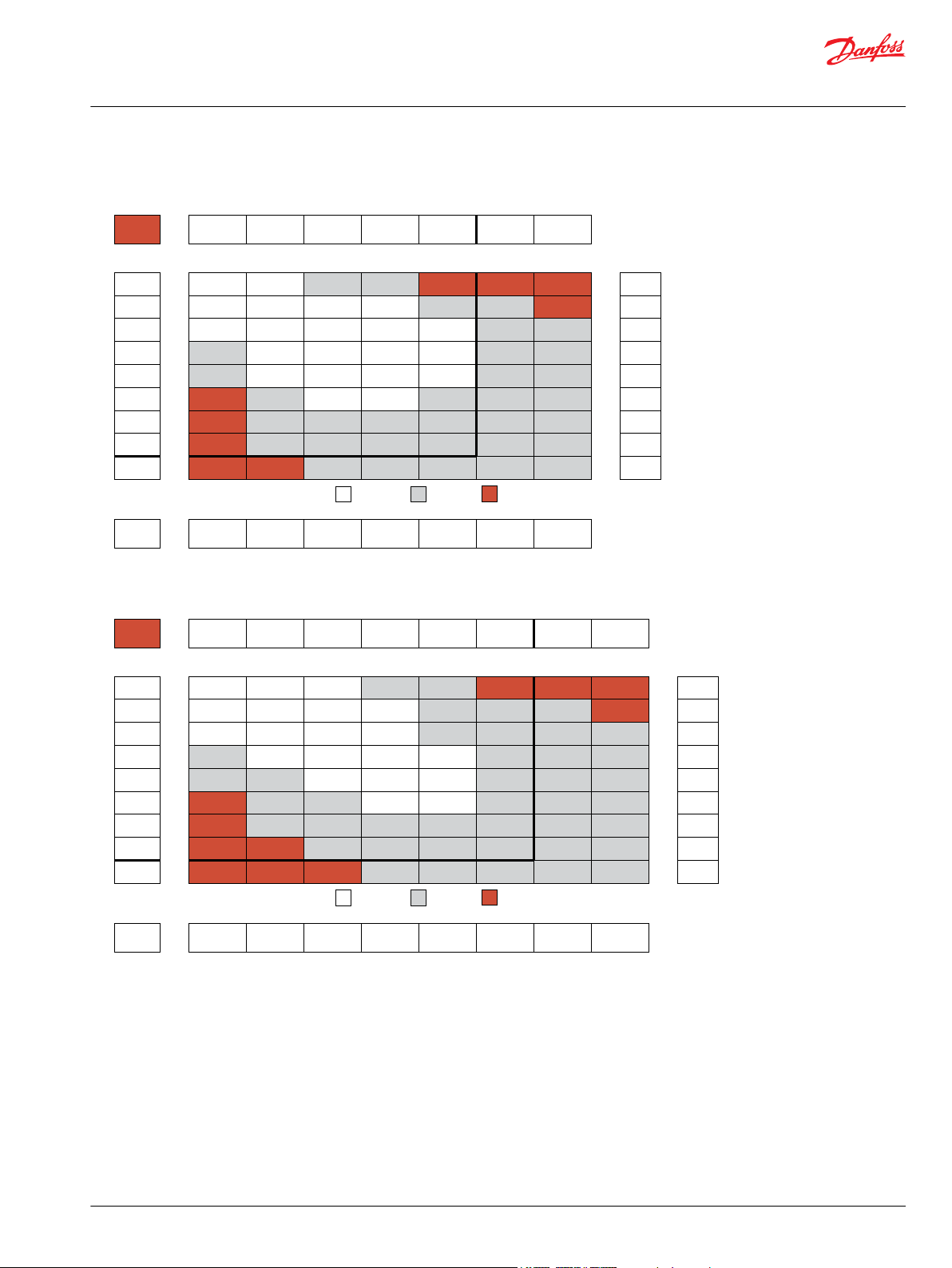
38
76
115
153
192
230
268
35
74
113
150
190
226
266
308
384
30
70
110
146
186
223
262
305
381
23
64
105
138
181
218
258
299
376
56
98
132
174
210
250
292
372
48
92
120
163
200
240
284
358
62
86
133
167
209
256
330
[460]
[443]
[425]
[407]
[319]
[195]
[44]
52
50
48
46
36
22
5
[965]
[991]
[974]
[903]
[814]
[708]
[620]
[513]
[372]
109
112
110
102
92
80
70
58
42
[1451]
[1478]
[1460]
[1407]
[1336]
[1257]
[1151]
[1044]
[779]
164
167
165
159
151
142
130
118
88
[1929]
[1947]
[1929]
[1912]
[1823]
[1708]
[1558]
[1381]
[1097]
218
220
218
216
206
193
176
156
124
[2390]
[2425]
[2372]
[2283]
[2089]
[1903]
[1752]
[1531]
270
274
268
258
236
215
198
173
[2744]
[2761]
[2682]
[2567]
[2496]
[2407]
[2239]
[1947]
310
312
303
290
282
272
253
220
[3637]
[3593]
[3522]
[3416]
[3310]
[3186]
[2903]
411
406
398
386
374
360
328
Torque - Nm [lb-in], Speed rpm
Flow - lpm [gpm]
21 [300] 41 [600] 62 [900] 83 [1200] 103 [1500] 124 [1800] 166 [2400]
Max. Inter.Max. Cont.
66 [582] 128 [1135] 194 [1717] 260 [2298] 322 [2852] 388 [3434] 519 [4597]
Theoretical Torque - Nm [lb-in]
Max.
Inter.
Max.
Cont.
200
8 [2]
15 [4]
23 [6]
30 [8]
38 [10]
45 [12]
53 [14]
61 [16]
76 [20]
39
77
116
154
193
231
270
308
385
Theoretical rpm
Overall Efficiency -
70 - 100%
40 - 69%
0 - 39%
Intermittent Ratings - 10% of Operation
Displacement tested at 45°C [113°F] with an oil viscosity of 46cSt [213 SUS]
Pressure - bar [psi]
mm [in]
Rotor
Width
25.9
[1.020]
197 cm3 [12.0 in3] / rev
P109604
31
62
94
125
158
188
220
30
61
93
124
156
187
219
248
312
28
58
92
121
155
186
217
244
309
23
55
87
117
151
184
214
241
305
19
51
83
113
147
180
211
237
302
47
81
110
145
176
209
235
300
38
67
97
136
164
194
223
285
27
57
88
121
150
181
210
268
[513]
[540]
[513]
[451]
[354]
[257]
[195]
58
61
58
51
40
29
22
[1044]
[1080]
[1027]
[991]
[867]
[735]
[593]
[460]
[212]
118
122
116
112
98
83
67
52
24
[1708]
[1682]
[1637]
[1575]
[1496]
[1381]
[1221]
[1089]
[743]
193
190
185
178
169
156
138
123
84
[2292]
[2248]
[2213]
[2168]
[2089]
[2036]
[1894]
[1682]
[1460]
259
254
250
245
236
230
214
190
165
[2655]
[2673]
[2611]
[2567]
[2513]
[2451]
[2319]
[2062]
[1788]
300
302
295
290
284
277
262
233
202
[2805]
[2726]
[2690]
[2637]
[2496]
[2301]
[2159]
[1841]
317
308
304
298
282
260
244
208
[2513]
[2434]
[2390]
[2319]
[2239]
[2142]
[2062]
[1805]
414
412
406
390
372
355
335
298
[3983]
[3947]
[3885]
[3797]
[3664]
[3496]
[3328]
[2965]
450
446
439
429
414
395
376
335
Torque - Nm [lb-in], Speed rpm
Flow - lpm [gpm]
21 [300] 41 [600] 62 [900] 83 [1200] 97 [1400] 103 [1500] 138 [2000]
Max. Inter.Max. Cont.
80 [712] 157 [1390] 237 [2101] 318 [2813] 371 [3288] 394 [3491] 528 [4677]
155 [2250]
594 [5253]
Theoretical Torque - Nm [lb-in]
Max.
Inter.
Max.
Cont.
241 cm3 [14.7 in3] / rev
250
8 [2]
15 [4]
23 [6]
30 [8]
38 [10]
45 [12]
53 [14]
61 [16]
76 [20]
32
63
94
126
158
189
220
252
315
Theoretical rpm
Overall Efficiency -
70 - 100%
40 - 69%
0 - 39%
Intermittent Ratings - 10% of Operation
Displacement tested at 45°C [113°F] with an oil viscosity of 46cSt [213 SUS]
Pressure - bar [psi]
mm [in]
Rotor
Width
32.5
[1.280]
P109605
Technical Information
Orbital Motors Type WD, WP and WR
WD Product Line
200cc Displacement Performance
250cc Displacement Performance
©
Danfoss | December 2019 BC267362166283en-000201 | 27
Page 28

25
49
74
101
125
147
175
22
47
72
98
123
146
174
199
250
20
43
69
95
121
143
171
197
246
35
59
90
115
139
166
187
240
30
54
84
112
132
160
182
236
33
65
90
118
138
166
217
22
53
80
105
127
152
206
[779]
[788]
[690]
[531]
[531]
[327]
[133]
88
89
78
60
60
37
15
[1540]
[1505]
[1434]
[1336]
[1257]
[1133]
[956]
[779]
[531]
174
170
162
151
142
128
108
88
60
[2257]
[2328]
[2177]
[2124]
[2036]
[1947]
[1841]
[1735]
[1593]
255
263
246
240
230
220
208
196
180
[3115]
[3053]
[3000]
[2965]
[2876]
[2814]
[2655]
[2478]
352
345
339
335
325
318
300
280
[3505]
[3469]
[3416]
[3363]
[3275]
[3142]
[3009]
[2885]
396
392
386
380
370
355
340
326
[4708]
[4655]
[4549]
[4425]
[4301]
[4115]
[3912]
532
526
514
500
486
465
442
[5098]
[5009]
[4938]
[4744]
[4567]
[4372]
[4142]
576
566
558
536
516
494
468
Torque - Nm [lb-in], Speed rpm
Flow - lpm [gpm]
21 [300] 41 [600] 62 [900] 90 [1300] 103 [1500] 138 [2000] 155 [2250]
Max. Inter.Max. Cont.
101 [897] 198 [1752] 299 [2649] 435 [3846] 497 [4401] 666 [5896] 748 [6623]
Theoretical Torque - Nm [lb-in]
Max.
Inter.
Max.
Cont.
303 cm3 [18.5 in3] / rev
315
8 [2]
15 [4]
23 [6]
30 [8]
38 [10]
45 [12]
53 [14]
61 [16]
76 [20]
25
50
75
100
125
150
175
200
250
Theoretical rpm
Overall Efficiency -
70 - 100%
40 - 69%
0 - 39%
Intermittent Ratings - 10% of Operation
Displacement tested at 45°C [113°F] with an oil viscosity of 46cSt [213 SUS]
Pressure - bar [psi]
mm [in]
Rotor
Width
40.9
[1.610]
P109606
19
39
59
77
100
120
137
150
18
37
57
75
97
117
134
154
189
14
33
52
73
93
113
131
151
187
11
28
43
67
89
109
129
148
185
25
39
60
81
97
124
138
182
17
32
49
70
84
113
130
178
[929]
[876]
[805]
[637]
[549]
[451]
[336]
[177]
105
99
91
72
62
51
38
20
[1929]
[1832]
[1726]
[1646]
[1575]
[1451]
[1257]
[1071]
[867]
218
207
195
186
178
164
142
121
98
[3186]
[3044]
[2974]
[2876]
[2779]
[2744]
[2513]
[2301]
[2071]
360
344
336
325
314
310
284
260
234
[3960]
[3637]
[3567]
[3522]
[3487]
[3345]
[3186]
[2991]
[2726]
417
411
403
398
394
378
360
338
308
[4248]
[4260]
[4124]
[4053]
[3965]
[3797]
[3629]
[3398]
480
478
466
458
448
429
410
384
[5151]
[5089]
[5036]
[4956]
[4868]
[4708]
[4522]
[4301]
582
575
569
560
550
532
511
486
Torque - Nm [lb-in], Speed rpm
Flow - lpm [gpm]
21 [300] 41 [600] 69 [1000] 83 [1200] 97 [1400] 121 [1750]
Max. Inter.Max. Cont.
129 [1142] 252 [2229] 424 [3751] 510 [4513] 596 [5274] 743 [6579]
Theoretical Torque - Nm [lb-in]
Max.
Inter.
Max.
Cont.
400
8 [2]
15 [4]
23 [6]
30 [8]
38 [10]
45 [12]
53 [14]
61 [16]
76 [20]
20
39
59
79
98
118
137
157
196
Theoretical rpm
Overall Efficiency -
70 - 100%
40 - 69%
0 - 39%
Intermittent Ratings - 10% of Operation
Displacement tested at 45°C [113°F] with an oil viscosity of 46cSt [213 SUS]
Pressure - bar [psi]
mm [in]
Rotor
Width
52.1
[2.050]
386 cm3 [23.5 in3] / rev
P109607
Technical Information
Orbital Motors Type WD, WP and WR
WD Product Line
315cc Displacement Performance
400cc Displacement Performance
WD 145/146 Series
28 | © Danfoss | December 2019 BC267362166283en-000201
145/146 Series Housings
Dimensions shown are without paint. Paint thickness can be up to 0.13 [.005].
Dimensions are charted in 145/146 Series Technical Data on page 30
(TP) - Taller pilot height. Refer to detailed drawing for dimensional differences.
Page 29
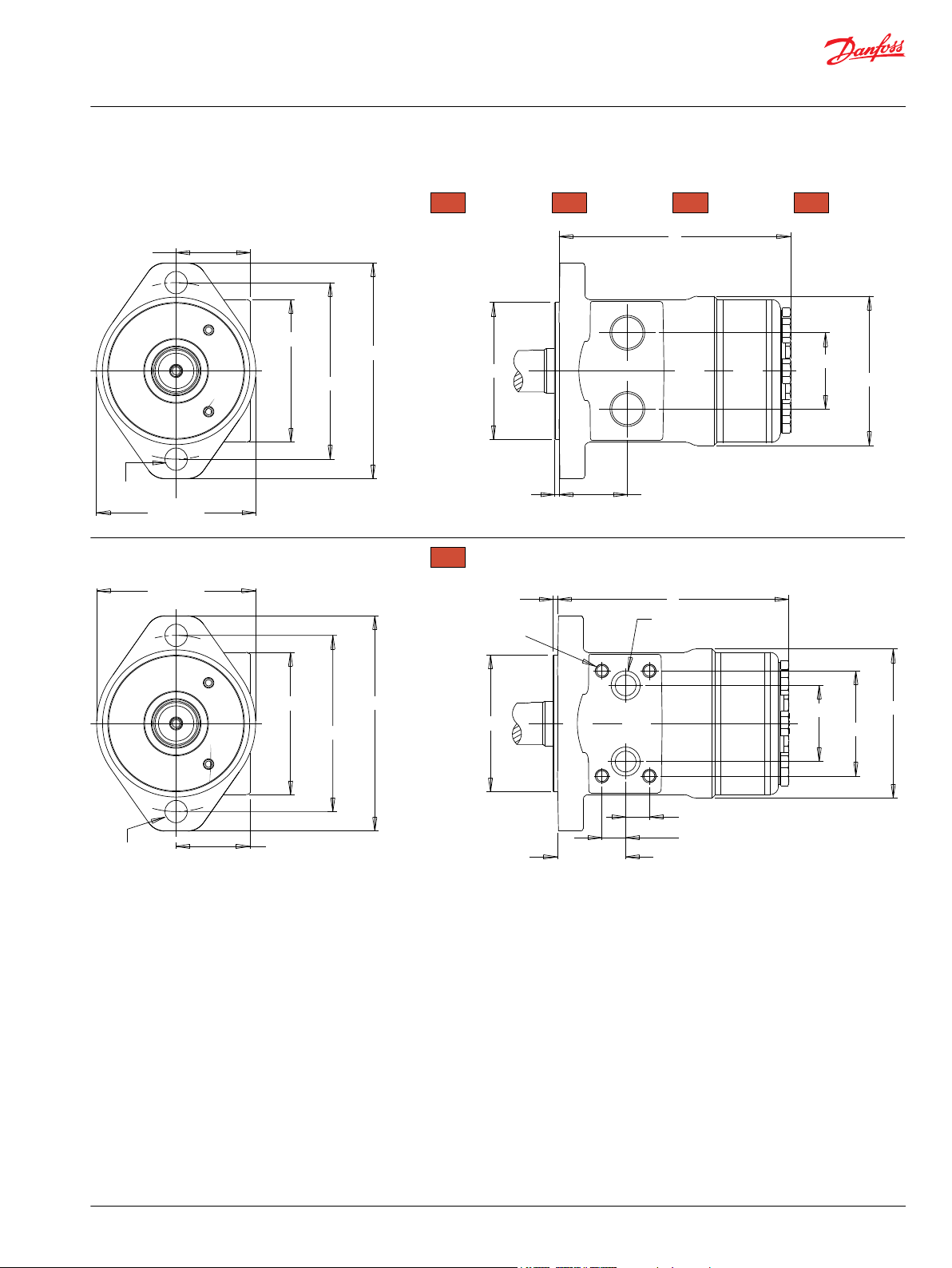
44.6 [1.756]
130 [5.118]
86 [3.386]
106.4 [4.189]
(2) Ø13.5 [.531]
96 [3.780]
Ø82.5 [3.248]
B
46 [1.811]
41.2 [1.622] - A10, A11, A18
36.2 [1.422] - A68
90 [3.543]
B
A
130 [5.118]
86 [3.386]
Ø106.4 [4.189]
44.6 [1.756]
96 [3.780]
2.6[.102]
B
41.2 [1.622]
14.3 [0.563]
14.3 [0.563]
46 [1.811]
63.5 [2.500]
90 [3.543]
82.5 [3.248]
(2) Ø13.5 [.531]
SPOTFACE Ø 17.5 [0.689]
2 [0.079] DEEP MIN.
(4) 5/16-18 UNC
13 [0.519] DEEP MIN.
B
A
2.6 [.102] - A10, A11, A18
8.0 [.315] - A68
P109608
A10
1/2-14 NPT
2-HOLE, SAE A MOUNT, ALIGNED PORTS
A68
G 1/2 (TP)
A17
1/2” Drilled
2-HOLE, SAE A MOUNT, ALIGNED MANIFOLD PORTS
A11
7/8-14 UNF
A18
G 1/2
Technical Information
Orbital Motors Type WD, WP and WR
WD Product Line
©
Danfoss | December 2019 BC267362166283en-000201 | 29
Page 30
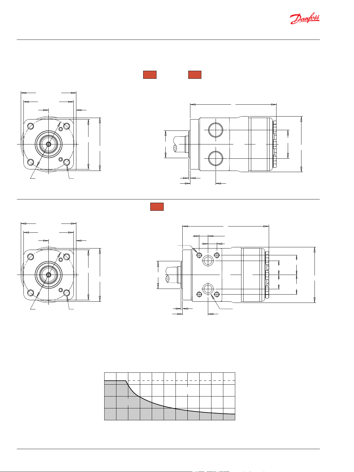
81 [3.189]
44.6 [1.756]
81 [3.189]
Ø 82.55 [3.250]
86 [3.386]
89.6 [3.528]
(4) 3/8-16 UNC
13 [.512] Min. Depth
Ø 44.4 [1.748]
B
2.6 [.102]
41.2 [1.622]
23 [.91]
31.8 [1.25]
31.8 [1.25]
23 [.91]
90 [3.543]
B
A
14.3 [.56]
14.3 [.56]
Spotface: Ø 17.5 [0.689]
2 [0.079] Min. Depth
(4) 5/16-18 UNC
13 [0.519] Min. Depth
F37
1/2” Drilled
4-HOLE, SQUARE MOUNT, ALIGNED MANIFOLD PORTS
P109609
81 [3.189]
44.6 [1.756]
81 [3.189]
Ø 82.55 [3.250]
86 [3.386]
89.6 [3.528]
Ø 44.4 [1.748]
B
2.6 [.102]
41.2 [1.622]
46 [1.811]
90 [3.543]
B
A
(4) 3/8-16 UNC
DEPTH 13 [.512] MIN.
F30
1/2-14 NPT
4-HOLE, SQUARE MOUNT, ALIGNED PORTS
F31
7/8-14 UNF
276 [4000]
207 [3000]
69 [1000]
138 [2000]
bar [psi]
0 1000900 rpm600 800700500400300200100
Continuous
Intermittent
P109610
Technical Information
Orbital Motors Type WD, WP and WR
WD Product Line
145/146 Series Technical Data
Permissible Shaft Seal Press
The curve below represents allowable seal pressure at various speeds. Operation in the gray area results
in maintaining the rated life of the shaft seal. Actual shaft seal pressure depends on motor configuration.
30 | © Danfoss | December 2019 BC267362166283en-000201
Page 31
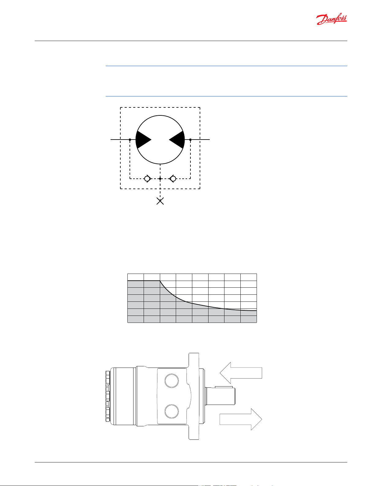
P109354
6000 [1350]
N [lbf]
4000 [900]
2000 [450]
0 600 rpm700500400300200100 P109611
150 daN [337 lb]
200 daN [450 lb]
P109612
Technical Information
Orbital Motors Type WD, WP and WR
WD Product Line
With check valves and drain connection, the shaft seal pressure equals pressure in the drain line. With
check valves and no drain connection, shaft seal pressure is identical to output pressure. No check valves
and no drain connection, the shaft seal pressure is identical to the average value of input and output
pressure.
Allowable Shaft Load / Bearing Curve
The bearing curve below represents the side load capacity of the motor at the centerline of the key for
various motor speeds. Operating conditions within the shaded area will maintain acceptable oil film
lubrication with recommended fluids. Operating conditions outside the shaded area are susceptible to
motor failure due to oil starvation and/or excessive heat generation. Fluids with low lubricity or low
viscosity may require the maximum load and speed ratings to be derated to provide acceptable motor
life and performance.
Thrust Load
©
Danfoss | December 2019 BC267362166283en-000201 | 31
Page 32

Technical Information
Orbital Motors Type WD, WP and WR
WD Product Line
Length and Weight Charts
The overall motor weights listed in this chart were calculated using the heaviest of the housing options
associated with that mounting flange to end of motor dimension. 145 & 146 series motor weights can
vary ± 0.5 kg [1 lb] depending on model configurations such as housing, shaft, endcover, options etc.
Dimension B is the overall motor length from the rear of the motor to the mounting flange surface and is
referenced on detailed housing drawings listed in 145/146 Series Housings on page 28.
Dimension B
# 3mm Pilot 8mm Pilot Weight
025 119 [4.67] 114 [4.47] 5.20 [11.5]
032 120 [4.71] 115 [4.51] 5.24 [11.6]
040 121 [4.77] 116 [4.57] 5.29 [11.7]
050 121 [4.77] 116 [4.57] 5.29 [11.7]
060 123 [4.83] 118 [4.63] 5.34 [11.8]
080 125 [4.92] 120 [4.72] 5.42 [12.0]
100 128 [5.02] 123 [4.82] 5.51 [12.2]
125 131 [5.17] 126 [4.97] 5.65 [12.5]
160 135 [5.33] 130 [5.13] 5.79 [12.8]
200 141 [5.53] 136 [5.33] 5.97 [13.2]
250 147 [5.79] 142 [5.59] 6.20 [13.7]
315 156 [6.12] 151 [5.92] 6.49 [14.3]
400 167 [6.56] 162 [6.36] 6.88 [15.2]
mm [in] mm [in] kg [lb]
32 | © Danfoss | December 2019 BC267362166283en-000201
Page 33

31.75 [1.250]
31.45 [1.238]
5 [.20]
C
*16 [.62]
5 [.20]
31.75 [1.250]
31.45 [1.238]
7.95 [.313]
7.93 [.312]
28.30 [1.114]
27.89 [1.098]
25.4 [1.000]
25.4 [0.999]
25.4 [1.000]
25.4 [0.999]
25.4 [1.000]
M8 X 1.25,
Min. Depth 20 [.79]
6.35 [.250]
6.3 [.248]
6.35 [.250]
6.3 [.248]
28.15 [1.122]
27.95 [1.100]
1/4-20 UNC,
Min. Depth 16 [.63]
19.1 [.761]
18.0 [.709]
15.5 [.610]
25.4 [1.000]
25.4 [.999]
1/4-20 UNC-2B
16 [.630] Min.
1/4-20 UNC, Min. Depth 16 [.63]
27.98 [1.102]
27.70 [1.091]
6.98 [.275]
6.90 [.271]
Ø25.02 [.985]
Ø25.00 [.984]
6.38 [.251]
6.35 [.250]
Ø 25.4 [1.000]
Ø 25.1 [.990]
Ø22.3 [.878]
Ø22.2 [.874]
Ø25.4 [.998]
Ø25.3 [.996]
39.9 [1.571]
39.9 [1.571]
30.4 [1.196]
C
C
C
2
C
C
C
01
7/8” 13 Tooth Spline
Max. Torque: 170 Nm [1500 lb-in] Max. Torque: 678 Nm [6000 lb-in]
02
1” 6B Spline, 1/4-20 Tap
Max. Torque: 678 Nm [6000 lb-in]
04
1” 6B Spline, M8x1.25 Tap
10
1” Straight
Max. Torque: 655 Nm [5800 lb-in]
Max. Torque: 678 Nm [6000 lb-in]
15
1” Straight Extended
G8
1” Straight Nickel Plated
B1
1” Straight, Woodruff Key
Max. Torque: 655 Nm [5800 lb-in]
12
25mm Straight
16
25mm Straight Extended
53
1” - 10.3 [.406] Pinhole
66
1” - 8.0 [.315] Pinhole
* Dimension for 66 shaft is 11.2 [.44]
C
2
C
2
1/4-20 UNC,
Min. Depth 16 [.63]
6B Spline
SAE J499 Standard
16/32 Pitch Standard
ANSI B92.1-1996 Spline
Technical Information
Orbital Motors Type WD, WP and WR
WD Product Line
145/146 Series Shafts
Mounting / Shaft Length Chart
Dimension C is the overall distance from the motor mounting surface to the end of the shaft.
Additional shaft length information, if necessary, is noted as C2 and does not increase or decrease the
listed C dimensions in this chart. The overall shaft lengths are already factored into the overall distance
from the mounting surface to the end of the shaft.
©
Danfoss | December 2019 BC267362166283en-000201 | 33
Page 34

Technical Information
Orbital Motors Type WD, WP and WR
WD Product Line
Dimension C
# 3mm Pilot 8mm Pilot C
01 45.4 [1.803] 50.8 [2.000] N/A
02 45.4 [1.803] 50.8 [2.000] N/A
04 45.4 [1.803] 50.8 [2.000] N/A
10 45.4 [1.803] 50.8 [2.000] 39.9 [1.571]
12 45.4 [1.803] 50.8 [2.000] 39.9 [1.571]
15 62.1 [2.445] 67.5 [2.657] 56.0 [2.205]
16 62.1 [2.445] 67.5 [2.657] 56.0 [2.205]
53 45.4 [1.803] 50.8 [2.000] 39.9 [1.571]
66 50.4 [1.984] 55.8 [2.197] 44.9 [1.768]
B1 45.4 [1.803] 50.8 [2.000] N/A
G8 50.4 [1.984] 55.8 [2.197] 40.6 [1.599]
2
mm [in] mm [in] mm [in]
34 | © Danfoss | December 2019 BC267362166283en-000201
Page 35

1 2 3 4 5 6 7 8
25 cm3/rev [1.5 in3/rev]
31 cm3/rev [1.9 in3/rev]
40 cm3/rev [2.4 in3/rev]
48 cm3/rev [2.9 in3/rev]
59 cm3/rev [3.6 in3/rev]
80 cm3/rev [4.9 in3/rev]
96 cm3/rev [5.9 in3/rev]
Standard Rotation Reverse Rotation
The 145 & 146 series are bi-directional.
123 cm3/rev [7.5 in3/rev]
158 cm3/rev [9.6 in3/rev]
197 cm3/rev [12.0 in3/rev]
241 cm3/rev [14.7 in3/rev]
303 cm3/rev [18.5 in3/rev]
386 cm3/rev [23.5 in3/rev]
2-Hole, SAE A Mount, Aligned Ports, 1/2-14 NPT
2-Hole, SAE A Mount, Aligned Ports, 7/8-14 UNF
2-Hole, SAE A Mount, Aligned Manifold Ports, 1/2” Drilled
2-Hole, SAE A Mount, Aligned Ports, G 1/2
2-Hole, SAE A Mount, Aligned Ports, G 1/2 (TP)
4-Hole, Square Mount, Aligned Ports, 1/2-14 NPT
4-Hole, Square Mount, Aligned Ports, 7/8-14 UNF
4-Hole, Square Mount, Aligned Manifold Ports, 1/2” Drilled
7/8” 13 Tooth Spline
1” 6B Spline, 1/4-20 Tap
1” 6B Spline, M8x1.25 Tap
1” Straight
25mm Straight
1” Straight Extended
25mm Straight Extended
1” - 10.3 [.406] Pinhole
1” - 8.0 [.315] Pinhole
1” Straight, Woodruff Key
1” Straight Nickel Plated
Black
Black, Unpainted Mounting Surface
Standard
Speed Sensor, Dual, 4-Pin Male Weatherpack Connector
Speed Sensor, Dual, 4-Pin M12 Male Connector
Speed Sensor, Single, 3-Pin Male Weatherpack Connector
Speed Sensor, Single, 4-Pin M12 Male Connector
None
Freeturning Rotor
Slinger Seal
No Check Valves Installed
If the BE option is selected in Step 8, the G8 shaft is recommended for added shaft protection.
The 15 & 16 extended shafts are designed for use with one of the speed sensor options listed in
STEP 7.
(TP) - Tall pilot. Speed sensor option is not available on tall pilot housings.
None
145
1. CHOOSE SERIES DESIGNATION
2. SELECT A DISPLACEMENT OPTION
025
032
040
050
060
080
100
125
160
200
250
315
400
3. SELECT A MOUNT & PORT OPTION
A10
A11
A17
A18
A68
F30
F31
F37
4. SELECT A SHAFT OPTION
01
02
04
10
12
15
16
53
66
B1
G8
5. SELECT A PAINT OPTION
A
B
6. SELECT A VALVE CAVITY / CARTRIDGE OPTION
7. SELECT AN ADD-ON OPTION
A
W
X
Y
Z
8. SELECT A MISCELLANEOUS OPTION
AA
AC
BE
FB
146
A
P109614
Technical Information
Orbital Motors Type WD, WP and WR
WD Product Line
145/146 Series Order Codes
©
Danfoss | December 2019 BC267362166283en-000201 | 35
Page 36

P109635
Technical Information
Orbital Motors Type WD, WP and WR
WP Product Line
WP Introduction
Overview
The WP motor series is an economical alternative to more complex roller gerotor designs and still
provides high efficiency across a wide performance range. These motors are intended for light-duty
applications requiring high torque in a compact package and are suitable for industrial and mobile
applications including car wash brushes, food processing equipment, conveyors, machine tools,
agricultural equipment, sweepers, skid steer attachments, and more.
Features / Benefits
•
Built-in check valves offer versatility and increased seal life.
•
A variety of mounts and shafts provide flexibility in application design.
•
Spool valve design gives superior performance and smooth operation over a wide speed and torque
range.
•
Standard high pressure shaft seals offer superior seal life and performance.
Typical Applications
agriculture equipment, conveyors, carwashes, sweepers, food processing, grain augers, spreaders, feed
rollers, augers, brush drives and more
Series Descriptions
155/156 - Hydraulic Motor (standard)
36 | © Danfoss | December 2019 BC267362166283en-000201
Page 37

P109636
Technical Information
Orbital Motors Type WD, WP and WR
WP Product Line
157/158 - Hydraulic Motor (with needle bearing)
Specifications
Performance data is typical. Performance of production units varies slightly from one motor to another.
Running at intermittent ratings should not exceed 10% of every minute of operation.
CODE
025 25 [1.5] 1570 1687 40 [11] 45 [12] 35 [310] 48 [425] 100 [1450] 140 [2030] 225 [3260]
032 32 [2.0] 1550 1674 50 [13] 55 [15] 45 [398] 57 [504] 100 [1450] 140 [2030] 225 [3260]
040 40 [2.5] 1471 1670 60 [16] 70 [19] 65 [575] 74 [655] 100 [1450] 140 [2030] 225 [3260]
050 50 [3.0] 1208 1500 60 [16] 75 [20] 91 [805] 108 [956] 140 [2030] 175 [2540] 240 [3480]
060 59 [3.6] 1185 1271 60 [16] 75 [20] 125 [1106] 136 [1204] 160 [2320] 175 [2540] 240 [3480]
080 78 [4.8] 896 960 60 [16] 75 [20] 164 [1451] 183 [1620] 160 [2320] 175 [2540] 240 [3480]
100 96 [5.9] 728 780 60 [16] 75 [20] 195 [1726] 213 [1885] 160 [2320] 175 [2540] 240 [3480]
125 125 [7.6] 559 599 60 [16] 75 [20] 258 [2285] 278 [2460] 160 [2320] 175 [2540] 240 [3480]
160 159 [9.7] 452 483 60 [16] 75 [20] 321 [2840] 362 [3205] 160 [2320] 175 [2540] 240 [3480]
200 190 [11.6] 367 385 60 [16] 75 [20] 380 [3365] 420 [3720] 150 [2180] 175 [2540] 240 [3480]
250 240 [14.6] 291 312 60 [16] 75 [20] 445 [3940] 557 [4930] 140 [2030] 175 [2540] 240 [3480]
315 303 [18.5] 228 245 60 [16] 75 [20] 460 [4071] 602 [5330] 120 [1740] 160 [2320] 200 [2900]
400 388 [23.7] 155 189 60 [16] 75 [20] 488 [4320] 625 [5532] 95 [1380] 125 [1810] 180 [2610]
Displacement
cm3 [in3]
Max. Speed
rpm
cont. inter. cont. inter. cont. inter. cont. inter. peak
Max. Flow
lpm [gpm]
Max. Torque
Nm [lb-in]
Max. Pressure
bar [psi]
WP Functional Charts
Performance data is typical. Performance of production units varies slightly from one motor to another.
Operating at maximum continuous pressure and maximum continuous flow simultaneously is not
recommended. For additional information on product testing please refer to Product Testing on page 7.
©
Danfoss | December 2019 BC267362166283en-000201 | 37
Page 38

186
386
568
777
972
1167
1360
1570
160
352
537
736
920
1122
1318
1503
1687
134
323
505
692
870
1088
1282
1476
1636
101
280
467
660
840
1055
1258
1432
1600
106
255
431
608
803
998
1216
1394
1558
210
390
566
756
976
1160
1359
1516
[80]
[88]
[80]
[71]
[62]
[53]
[44]
[44]
9
10
9
8
7
6
5
5
[159]
[159]
[168]
[168]
[159]
[150]
[142]
[133]
[115]
18
18
19
19
18
17
16
15
13
[221]
[230]
[230]
[221]
[230]
[221]
[212]
[195]
[177]
25
26
26
25
26
25
24
22
20
[283]
[301]
[310]
[292]
[283]
[283]
[274]
[274]
[248]
32
34
35
33
32
32
31
31
28
[310]
[327]
[336]
[345]
[345]
[345]
[327]
[319]
[301]
35
37
38
39
39
39
37
36
34
[425]
[389]
[398]
[398]
[389]
[381]
[363]
[345]
48
44
45
45
44
43
41
39
Torque - Nm [lb-in], Speed rpm
Flow - lpm [gpm]
30 [435] 60 [870] 80 [1160] 100 [1450] 120 [1740] 140 [2030]
Max. Inter.Max. Cont.
12 [106] 24 [211] 32 [282] 40 [352] 48 [423] 56 [493]
Theoretical Torque - Nm [lb-in]
Max.
Inter.
Max.
Cont.
025
5 [1.3]
10 [2.6]
15 [4.0]
20 [5.3]
25 [6.6]
30 [7.9]
35 [9.2]
40 [10.6]
45 [11.9]
200
400
600
800
1000
1200
1400
1600
1800
Theoretical rpm
Overall Efficiency -
70 - 100%
40 - 69%
0 - 39%
Intermittent Ratings - 10% of Operation
Displacement tested at 45°C [113°F] with an oil viscosity of 46cSt [213 SUS]
Pressure - bar [psi]
mm [in]
Rotor
Width
4.1
[.160]
25 cm3 [1.5 in3] / rev
P109333
149
308
465
624
780
931
1086
1240
1400
1550
135
284
444
589
771
908
1066
1212
1382
1526
1674
114
270
429
575
751
895
1051
1190
1366
1500
1641
94
250
398
557
735
876
1030
1178
1340
1478
1617
240
378
544
719
857
1012
1145
1314
1452
1584
211
355
524
695
822
981
1121
1280
1418
1555
[97]
[106]
[97]
[88]
[80]
[71]
[62]
[62]
[53]
[44]
11
12
11
10
9
8
7
7
6
5
[212]
[239]
[230]
[221]
[212]
[204]
[177]
[168]
[159]
[142]
[106]
24
27
26
25
24
23
20
19
18
16
12
[310]
[327]
[319]
[310]
[301]
[283]
[257]
[239]
[230]
[212]
[177]
35
37
36
35
34
32
29
27
26
24
20
[327]
[381]
[398]
[389]
[372]
[354]
[345]
[336]
[310]
[274]
[248]
37
43
45
44
42
40
39
38
35
31
28
[407]
[425]
[407]
[398]
[398]
[381]
[381]
[372]
[354]
[301]
46
48
46
45
45
43
43
42
40
34
[496]
[504]
[496]
[478]
[460]
[451]
[442]
[425]
[407]
[345]
56
57
56
54
52
51
50
48
46
39
Torque - Nm [lb-in], Speed rpm
Flow - lpm [gpm]
30 [435] 60 [870] 80 [1160] 100 [1450] 120 [1740] 140 [2030]
Max. Inter.Max. Cont.
15 [135] 31 [271] 41 [361] 51 [451] 61 [541] 71 [631]
Theoretical Torque - Nm [lb-in]
Max.
Inter.
Max.
Cont.
032
5 [1.3]
10 [2.6]
15 [4.0]
20 [5.3]
25 [6.6]
30 [7.9]
35 [9.2]
40 [10.6]
45 [11.9]
50 [13.2]
55 [14.5]
156
313
469
625
781
938
1094
1250
1406
1563
1719
Theoretical rpm
Overall Efficiency -
70 - 100%
40 - 69%
0 - 39%
Intermittent Ratings - 10% of Operation
Displacement tested at 45°C [113°F] with an oil viscosity of 46cSt [213 SUS]
Pressure - bar [psi]
mm [in]
Rotor
Width
5.1
[.200]
32 cm3 [2.0 in3] / rev
P109334
Technical Information
Orbital Motors Type WD, WP and WR
WP Product Line
025 Displacement Performance
032 Displacement Performance
38 | © Danfoss | December 2019 BC267362166283en-000201
Page 39

113
238
482
730
968
1219
1471
98
222
458
704
949
1191
1428
1670
83
204
442
687
928
1173
1411
1653
60
182
423
668
908
1150
1387
1627
48
161
402
646
892
1127
1369
1612
114
381
624
870
1107
1341
1598
[133]
[124]
[115]
[106]
[88]
[62]
[35]
15
14
13
12
10
7
4
[274]
[274]
[283]
[265]
[239]
[221]
[204]
[142]
31
31
32
30
27
25
23
16
[336]
[363]
[363]
[345]
[345]
[327]
[301]
[265]
38
41
41
39
39
37
34
30
[425]
[478]
[469]
[451]
[451]
[434]
[407]
[363]
48
54
53
51
51
49
46
41
[496]
[549]
[575]
[558]
[540]
[522]
[496]
[460]
56
62
65
63
61
59
56
52
[619]
[655]
[655]
[637]
[628]
[602]
[566]
70
74
74
72
71
68
64
Torque - Nm [lb-in], Speed rpm
Flow - lpm [gpm]
30 [435] 60 [870] 80 [1160] 100 [1450] 120 [1740] 140 [2030]
Max. Inter.Max. Cont.
19 [168] 38 [336] 50 [442] 64 [566] 76 [673] 89 [788]
Theoretical Torque - Nm [lb-in]
Max.
Inter.
Max.
Cont.
040
5 [1.3]
10 [2.6]
20 [5.3]
30 [7.9]
40 [10.6]
50 [13.2]
60 [15.8]
70 [18.5]
125
250
500
750
1000
1250
1500
2000
Theoretical rpm
Overall Efficiency -
70 - 100%
40 - 69%
0 - 39%
Intermittent Ratings - 10% of Operation
Displacement tested at 45°C [113°F] with an oil viscosity of 46cSt [213 SUS]
Pressure - bar [psi]
mm [in]
Rotor
Width
6.6
[.260]
40 cm3 [2.5 in3] / rev
P109335
100
197
400
600
808
1009
1208
1410
85
196
386
585
800
1006
1200
1396
1500
75
174
371
571
790
986
1196
1382
1488
64
159
355
560
770
982
1188
1370
1473
48
146
341
540
766
964
1176
1358
1457
127
314
516
733
956
1160
1347
1439
101
292
499
703
930
1140
1334
1412
97
290
495
697
872
963
1315
1388
[168]
[177]
[159]
[133]
[106]
[80]
[53]
[27]
19
20
18
15
12
9
6
3
[345]
[336]
[336]
[327]
[274]
[239]
[212]
[150]
[133]
39
38
38
37
31
27
24
17
15
[425]
[442]
[460]
[442]
[398]
[363]
[327]
[283]
[265]
48
50
52
50
45
41
37
32
30
[549]
[558]
[566]
[566]
[522]
[487]
[469]
[389]
[354]
62
63
64
64
59
55
53
44
40
[664]
[690]
[690]
[681]
[646]
[602]
[566]
[513]
[496]
75
78
78
77
73
68
64
58
56
[814]
[796]
[788]
[770]
[743]
[726]
[708]
[681]
92
90
89
87
84
82
80
77
[903]
[920]
[912]
[876]
[867]
[841]
[823]
[779]
102
104
103
99
98
95
93
88
[947]
[956]
[947]
[938]
[929]
[903]
[867]
[823]
107
108
107
106
105
102
98
93
Torque - Nm [lb-in], Speed rpm
Flow - lpm [gpm]
30 [435] 60 [870] 80 [1160] 100 [1450] 120 [1740] 140 [2030] 160 [2320] 175 [2540]
Max. Inter.Max. Cont.
24 [212] 47 [416] 63 [558] 79 [699] 95 [841] 110 [973] 126 [1115] 138 [1221]
Theoretical Torque - Nm [lb-in]
Max.
Inter.
Max.
Cont.
050
5 [1.3]
10 [2.6]
20 [5.3]
30 [7.9]
40 [10.6]
50 [13.2]
60 [15.8]
70 [18.5]
75 [19.8]
101
202
404
606
808
1010
1212
1414
1515
Theoretical rpm
Overall Efficiency -
70 - 100%
40 - 69%
0 - 39%
Intermittent Ratings - 10% of Operation
Displacement tested at 45°C [113°F] with an oil viscosity of 46cSt [213 SUS]
Pressure - bar [psi]
mm [in]
Rotor
Width
6.6
[.260]
50 cm3 [3.0 in3] / rev
P109336
Technical Information
Orbital Motors Type WD, WP and WR
WP Product Line
040 Displacement Performance
050 Displacement Performance
©
Danfoss | December 2019 BC267362166283en-000201 | 39
Page 40

83
169
338
507
678
845
1014
1185
79
164
332
502
669
841
1005
1182
1271
72
155
320
493
660
833
999
1180
1265
64
142
309
482
645
818
992
1175
1256
51
135
290
468
630
805
982
1158
1241
38
124
276
454
616
792
968
1144
1228
108
245
424
594
770
956
1128
1212
88
222
400
582
754
933
1112
1196
[177]
[195]
[177]
[150]
[124]
[88]
[62]
[35]
20
22
20
17
14
10
7
4
[407]
[416]
[398]
[381]
[363]
[327]
[301]
[239]
[195]
46
47
45
43
41
37
34
27
22
[575]
[584]
[566]
[549]
[513]
[487]
[460]
[416]
[381]
65
66
64
62
58
55
52
47
43
[708]
[717]
[708]
[673]
[646]
[619]
[584]
[549]
[513]
80
81
80
76
73
70
66
62
58
[841]
[850]
[823]
[788]
[770]
[743]
[726]
[673]
[646]
95
96
93
89
87
84
82
76
73
[991]
[1000]
[982]
[965]
[929]
[903]
[876]
[823]
[761]
112
113
111
109
105
102
99
93
86
[1106]
[1088]
[1071]
[1035]
[1000]
[965]
[920]
[885]
125
123
121
117
113
109
104
100
[1204]
[1186]
[1159]
[1124]
[1080]
[1044]
[1009]
[973]
136
134
131
127
122
118
114
110
Torque - Nm [lb-in], Speed rpm
Flow - lpm [gpm]
30 [435] 60 [870] 80 [1160] 100 [1450] 120 [1740] 140 [2030] 160 [2320] 175 [2540]
Max. Inter.Max. Cont.
28 [249] 56 [499] 75 [665] 94 [831] 113 [998] 132 [1164] 150 [1330] 164 [1455]
Theoretical Torque - Nm [lb-in]
Max.
Inter.
Max.
Cont.
060
5 [1.3]
10 [2.6]
20 [5.3]
30 [7.9]
40 [10.6]
50 [13.2]
60 [15.8]
70 [18.5]
75 [19.8]
85
170
339
509
678
848
1017
1186
1271
Theoretical rpm
Overall Efficiency -
70 - 100%
40 - 69%
0 - 39%
Intermittent Ratings - 10% of Operation
Displacement tested at 45°C [113°F] with an oil viscosity of 46cSt [213 SUS]
Pressure - bar [psi]
mm [in]
Rotor
Width
8.0
[.314]
59 cm3 [3.6 in3] / rev
P109337
60
125
254
384
512
638
768
896
960
56
118
245
374
505
630
762
890
955
50
112
236
366
494
625
756
882
948
42
104
228
358
483
615
748
872
938
30
98
215
346
473
606
738
860
926
82
204
335
462
593
728
846
916
67
190
318
450
580
717
830
896
50
175
305
438
568
694
816
802
[283]
[274]
[230]
[212]
[168]
[124]
[88]
[53]
[27]
32
31
26
24
19
14
10
6
3
[549]
[566]
[531]
[496]
[469]
[407]
[372]
[319]
[239]
62
64
60
56
53
46
42
36
27
[708]
[743]
[743]
[717]
[664]
[619]
[584]
[496]
[442]
80
84
84
81
75
70
66
56
50
[938]
[920]
[903]
[885]
[850]
[814]
[761]
[690]
[655]
106
104
102
100
96
92
86
78
74
[1106]
[1062]
[1106]
[1080]
[1044]
[973]
[938]
[867]
[814]
125
120
125
122
118
110
106
98
92
[1257]
[1274]
[1257]
[1239]
[1195]
[1133]
[1044]
[1000]
142
144
142
140
135
128
118
113
[1434]
[1451]
[1416]
[1398]
[1381]
[1327]
[1239]
[1177]
162
164
160
158
156
150
140
133
[1549]
[1619]
[1549]
[1504]
[1487]
[1451]
[1416]
[1310]
175
183
175
170
168
164
160
148
Torque - Nm [lb-in], Speed rpm
Flow - lpm [gpm]
30 [435] 60 [870] 80 [1160] 100 [1450] 120 [1740] 140 [2030] 160 [2320] 175 [2540]
Max. Inter.Max. Cont.
37 [327] 75 [664] 100 [885] 125 [1106] 149 [1319] 174 [1540] 199 [1761] 218 [1929]
Theoretical Torque - Nm [lb-in]
Max.
Inter.
Max.
Cont.
080
5 [1.3]
10 [2.6]
20 [5.3]
30 [7.9]
40 [10.6]
50 [13.2]
60 [15.8]
70 [18.5]
75 [19.8]
64
128
256
385
513
641
769
897
962
Theoretical rpm
Overall Efficiency -
70 - 100%
40 - 69%
0 - 39%
Intermittent Ratings - 10% of Operation
Displacement tested at 45°C [113°F] with an oil viscosity of 46cSt [213 SUS]
Pressure - bar [psi]
mm [in]
Rotor
Width
10.4
[.410]
78 cm3 [4.8 in3] / rev
P109338
Technical Information
Orbital Motors Type WD, WP and WR
WP Product Line
060 Displacement Performance
080 Displacement Performance
40 | © Danfoss | December 2019 BC267362166283en-000201
Page 41
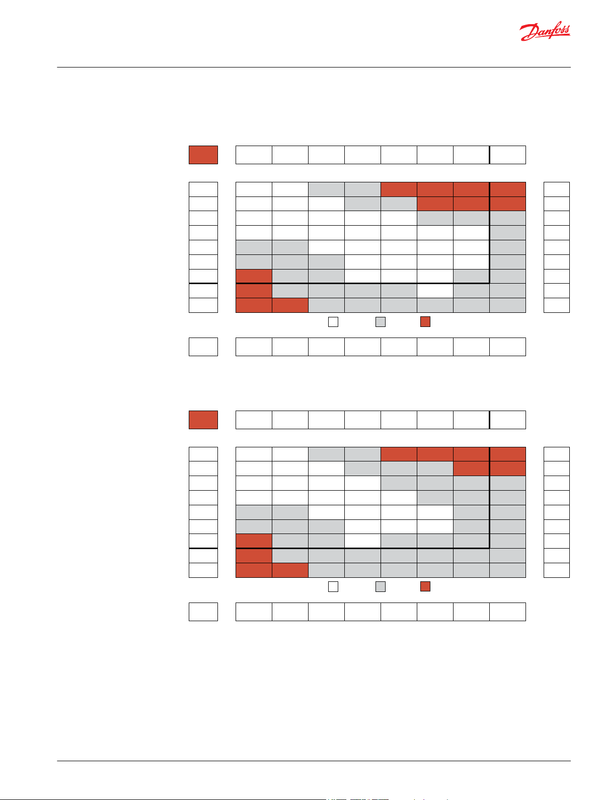
51
99
205
311
413
519
624
728
780
42
93
202
307
410
515
620
726
771
35
84
197
301
406
510
615
723
764
25
72
192
294
399
503
608
714
755
62
182
283
388
492
600
706
736
48
172
271
379
480
582
684
724
24
140
258
368
464
565
668
712
118
240
347
446
548
646
699
[381]
[381]
[363]
[345]
[257]
[177]
[150]
[97]
[53]
43
43
41
39
29
20
17
11
6
[726]
[743]
[699]
[655]
[558]
[460]
[469]
[372]
[310]
82
84
79
74
63
52
53
42
35
[965]
[956]
[947]
[894]
[823]
[752]
[735]
[646]
[540]
109
108
107
101
93
85
83
73
61
[1159]
[1177]
[1124]
[1115]
[1071]
[1018]
[982]
[823]
[788]
131
133
127
126
121
115
111
93
89
[1345]
[1363]
[1345]
[1327]
[1310]
[1221]
[1115]
[1044]
152
154
152
150
148
138
126
118
[1593]
[1575]
[1558]
[1522]
[1496]
[1460]
[1407]
[1283]
180
178
176
172
169
165
159
145
[1743]
[1770]
[1752]
[1726]
[1708]
[1619]
[1522]
[1381]
197
200
198
195
193
183
172
156
[1876]
[1885]
[1841]
[1796]
[1708]
[1619]
[1558]
212
213
208
203
193
183
176
Torque - Nm [lb-in], Speed rpm
Flow - lpm [gpm]
30 [435] 60 [870] 80 [1160] 100 [1450] 120 [1740] 140 [2030] 160 [2320] 175 [2540]
Max. Inter.Max. Cont.
46 [407] 92 [814] 122 [1080] 153 [1354] 183 [1623] 214 [1894] 245 [2168] 268 [2372]
Theoretical Torque - Nm [lb-in]
Max.
Inter.
Max.
Cont.
100
5 [1.3]
10 [2.6]
20 [5.3]
30 [7.9]
40 [10.6]
50 [13.2]
60 [15.8]
70 [18.5]
75 [19.8]
52
104
208
313
417
521
625
729
781
Theoretical rpm
Overall Efficiency -
70 - 100%
40 - 69%
0 - 39%
Intermittent Ratings - 10% of Operation
Displacement tested at 45°C [113°F] with an oil viscosity of 46cSt [213 SUS]
Pressure - bar [psi]
mm [in]
Rotor
Width
13.0
[.510]
96 cm3 [5.9 in3] / rev
P109339
38
78
158
238
319
399
479
559
35
74
152
232
316
396
478
555
599
32
69
144
225
312
392
475
548
594
27
62
135
215
308
383
470
538
588
54
124
210
300
368
463
524
576
45
110
198
288
354
454
516
565
35
94
168
262
338
443
500
536
78
155
238
326
434
488
524
[460]
[442]
[442]
[389]
[310]
[274]
[133]
[71]
52
50
50
44
35
31
15
8
[841]
[867]
[850]
[814]
[726]
[681]
[566]
[442]
[354]
95
98
96
92
82
77
64
50
40
[1195]
[1221]
[1168]
[1115]
[1044]
[956]
[858]
[796]
[628]
135
138
132
126
118
108
97
90
71
[1487]
[1522]
[1487]
[1451]
[1416]
[1372]
[1292]
[1239]
[1133]
168
172
168
164
160
155
146
140
128
[1681]
[1788]
[1752]
[1708]
[1611]
[1469]
[1434]
[1398]
190
202
198
193
182
166
162
158
[2071]
[2088]
[2053]
[2000]
[1947]
[1858]
[1805]
[1699]
234
236
232
226
220
210
204
192
[2283]
[2265]
[2319]
[2230]
[2106]
[1982]
[1850]
[1761]
258
256
262
252
238
224
209
199
[2460]
[2372]
[2354]
[2319]
[2265]
[2088]
[1982]
278
268
266
262
256
236
224
Torque - Nm [lb-in], Speed rpm
Flow - lpm [gpm]
30 [435] 60 [870] 80 [1160] 100 [1450] 120 [1740] 140 [2030] 160 [2320] 175 [2540]
Max. Inter.Max. Cont.
60 [531] 119 [1053] 159 [1407] 199 [1761] 239 [2115] 279 [2469] 318 [2814] 348 [3080]
Theoretical Torque - Nm [lb-in]
Max.
Inter.
Max.
Cont.
125
5 [1.3]
10 [2.6]
20 [5.3]
30 [7.9]
40 [10.6]
50 [13.2]
60 [15.8]
70 [18.5]
75 [19.8]
40
80
160
240
320
400
480
560
600
Theoretical rpm
Overall Efficiency -
70 - 100%
40 - 69%
0 - 39%
Intermittent Ratings - 10% of Operation
Displacement tested at 45°C [113°F] with an oil viscosity of 46cSt [213 SUS]
Pressure - bar [psi]
mm [in]
Rotor
Width
16.8
[.660]
125 cm3 [7.6 in3] / rev
P109340
Technical Information
Orbital Motors Type WD, WP and WR
WP Product Line
100 Displacement Performance
125 Displacement Performance
©
Danfoss | December 2019 BC267362166283en-000201 | 41
Page 42

30
63
128
193
257
323
387
452
483
25
60
125
190
255
320
384
451
481
18
56
121
187
252
316
380
448
477
10
52
116
183
248
312
375
444
472
48
110
179
244
306
371
436
466
37
100
173
239
299
366
430
460
86
160
224
288
358
423
450
78
144
211
275
346
412
436
[496]
[513]
[532]
[443]
[425]
[283]
[204]
[142]
[89]
56
58
60
50
48
32
23
16
10
[991]
[1018]
[1089]
[1035]
[1000]
[938]
[779]
[726]
[699]
112
115
123
117
113
106
88
82
79
[1363]
[1381]
[1434]
[1389]
[1372]
[1319]
[1177]
[1133]
[1097]
154
156
162
157
155
149
133
128
124
[1779]
[1814]
[1788]
[1743]
[1726]
[1664]
[1575]
[1505]
[1451]
201
205
202
197
195
188
178
170
164
[2168]
[2142]
[2106]
[2089]
[2080]
[1876]
[1823]
[1779]
245
242
238
236
235
212
206
201
[2522]
[2496]
[2460]
[2416]
[2363]
[2301]
[2257]
[2195]
285
282
278
273
267
260
255
248
[2894]
[2850]
[2814]
[2770]
[2726]
[2673]
[2620]
327
322
318
313
308
302
296
[3186]
[3168]
[3142]
[3115]
[3027]
[2929]
[2823]
360
358
355
352
342
331
319
Torque - Nm [lb-in], Speed rpm
Flow - lpm [gpm]
30 [435] 60 [870] 80 [1160] 100 [1450] 120 [1740] 140 [2030] 160 [2320] 175 [2540]
Max. Inter.Max. Cont.
74 [651] 147 [1302] 196 [1736] 245 [2170] 282 [2496] 343 [3038] 392 [3472] 429 [3798]
Theoretical Torque - Nm [lb-in]
Max.
Inter.
Max.
Cont.
160
5 [1.3]
10 [2.6]
20 [5.3]
30 [7.9]
40 [10.6]
50 [13.2]
60 [15.8]
70 [18.5]
75 [19.8]
32
65
130
194
258
323
387
453
485
Theoretical rpm
Overall Efficiency -
70 - 100%
40 - 69%
0 - 39%
Intermittent Ratings - 10% of Operation
Displacement tested at 45°C [113°F] with an oil viscosity of 46cSt [213 SUS]
Pressure - bar [psi]
mm [in]
Rotor
Width
20.8
[.820]
159 cm3 [9.7 in3] / rev
P109341
25
51
104
157
210
262
315
367
22
49
102
155
208
260
313
365
394
20
45
99
152
205
258
309
362
390
10
39
95
148
200
254
305
358
385
35
89
143
193
249
299
352
380
29
83
137
186
243
293
336
374
22
76
130
178
235
284
330
365
65
118
168
223
268
316
352
[664]
[690]
[655]
[619]
[575]
[478]
[319]
[133]
75
78
74
70
65
54
36
15
[1398]
[1416]
[1381]
[1345]
[1301]
[1257]
[1133]
[903]
[832]
158
160
156
152
147
142
128
102
94
[1770]
[1805]
[1770]
[1735]
[1681]
[1593]
[1469]
[1398]
[1292]
200
204
200
196
190
180
166
158
146
[2133]
[2230]
[2177]
[2124]
[2018]
[1965]
[1858]
[1788]
[1717]
241
252
246
240
228
222
210
202
194
[2575]
[2593]
[2566]
[2531]
[2451]
[2354]
[2248]
[2035]
291
293
290
286
277
266
254
230
[3080]
[3133]
[3115]
[3009]
[2947]
[2850]
[2673]
[2566]
348
354
352
340
333
322
302
290
[3336]
[3363]
[3345]
[3327]
[3150]
[3097]
[2894]
[2805]
377
380
378
376
356
350
327
317
[3681]
[3717]
[3699]
[3558]
[3540]
[3327]
[3221]
416
420
418
402
400
376
364
Torque - Nm [lb-in], Speed rpm
Flow - lpm [gpm]
30 [435] 60 [870] 80 [1160] 100 [1450] 115 [1670] 140 [2030] 150 [2180] 175 [2540]
Max. Inter.Max. Cont.
91 [803] 182 [1611] 242 [2142] 303 [2677] 348 [3079] 424 [3748] 454 [4016] 529 [4685]
Theoretical Torque - Nm [lb-in]
Max.
Inter.
Max.
Cont.
200
5 [1.3]
10 [2.6]
20 [5.3]
30 [7.9]
40 [10.6]
50 [13.2]
60 [15.8]
70 [18.5]
75 [19.8]
26
53
105
158
211
263
316
368
395
Theoretical rpm
Overall Efficiency -
70 - 100%
40 - 69%
0 - 39%
Intermittent Ratings - 10% of Operation
Displacement tested at 45°C [113°F] with an oil viscosity of 46cSt [213 SUS]
Pressure - bar [psi]
mm [in]
Rotor
Width
25.9
[1.020]
190 cm3 [11.6 in3] / rev
P109342
Technical Information
Orbital Motors Type WD, WP and WR
WP Product Line
160 Displacement Performance
200 Displacement Performance
42 | © Danfoss | December 2019 BC267362166283en-000201
Page 43
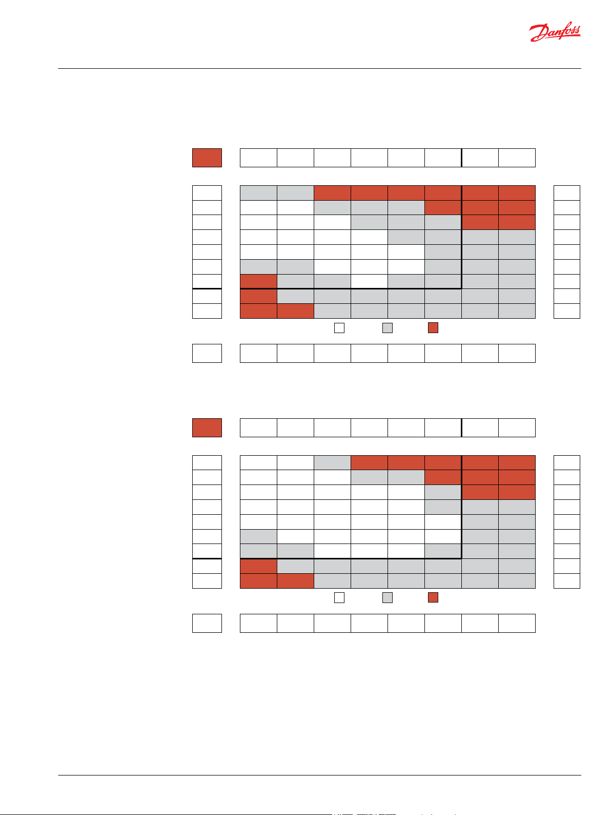
19
40
81
124
165
207
250
291
312
16
36
77
121
162
203
247
285
310
10
32
72
115
158
195
243
278
307
6
21
65
106
153
189
236
271
302
10
50
94
144
183
222
256
294
42
84
135
170
216
249
270
36
76
125
157
205
234
254
23
61
113
138
188
221
242
[788]
[814]
[796]
[761]
[726]
[611]
[425]
[327]
[230]
89
92
90
86
82
69
48
37
26
[1717]
[1735]
[1699]
[1637]
[1584]
[1496]
[1345]
[1230]
[1133]
194
196
192
185
179
169
152
139
128
[2336]
[2372]
[2336]
[2265]
[2195]
[2150]
[2035]
[1938]
[1814]
264
268
264
256
248
243
230
219
205
[2885]
[2912]
[2841]
[2779]
[2699]
[2593]
[2496]
[2327]
[2168]
326
329
321
314
305
293
282
263
245
[3487]
[3513]
[3469]
[3398]
[3345]
[3221]
[3035]
[2903]
394
397
392
384
378
364
343
328
[3938]
[3855]
[3814]
[3726]
[3602]
[3416]
[3310]
445
439
431
421
407
386
374
[4513]
[4442]
[4301]
[4204]
[4035]
[3903]
[3788]
510
502
486
475
456
441
428
[4903]
[4929]
[4823]
[4655]
[4496]
[4389]
[4257]
554
557
545
526
508
496
481
Torque - Nm [lb-in], Speed rpm
Flow - lpm [gpm]
30 [435] 60 [870] 85 [1230] 100 [1450] 125 [1810] 140 [2030] 160 [2320] 175 [2540]
Max. Inter.Max. Cont.
115 [1018] 229 [2027] 325 [2875] 382 [3381] 478 [4230] 535 [4735] 611 [5407] 669 [5920]
Theoretical Torque - Nm [lb-in]
Max.
Inter.
Max.
Cont.
250
5 [1.3]
10 [2.6]
20 [5.3]
30 [7.9]
40 [10.6]
50 [13.2]
60 [15.8]
70 [18.5]
75 [19.8]
21
42
83
125
167
208
250
292
313
Theoretical rpm
Overall Efficiency -
70 - 100%
40 - 69%
0 - 39%
Intermittent Ratings - 10% of Operation
Displacement tested at 45°C [113°F] with an oil viscosity of 46cSt [213 SUS]
Pressure - bar [psi]
mm [in]
Rotor
Width
32.5
[1.280]
240 cm3 [14.6 in3] / rev
P109343
P109344
16
31
64
98
129
164
195
228
245
13
29
62
94
126
160
192
226
242
10
25
58
90
122
155
188
223
238
6
21
54
85
118
150
183
218
233
17
49
79
113
144
176
212
228
43
70
106
136
170
206
222
32
62
99
127
164
196
215
23
56
76
119
157
188
206
[1089]
[1035]
[991]
[920]
[761]
[646]
[531]
[327]
[204]
123
117
112
104
86
73
60
37
23
[1770]
[1717]
[1735]
[1620]
[1487]
[1381]
[1239]
[1080]
[885]
200
194
196
183
168
156
140
122
100
[2496]
[2451]
[2434]
[2363]
[2230]
[2106]
[1974]
[1646]
[1540]
282
277
275
267
252
238
223
186
174
[3044]
[3027]
[3009]
[2850]
[2690]
[2549]
[2390]
[2248]
[2097]
344
342
340
322
304
288
270
254
237
[3531]
[3513]
[3452]
[3230]
[3098]
[2876]
[2735]
[2593]
399
397
390
365
350
325
309
293
[4071]
[3965]
[3894]
[3752]
[3505]
[3257]
[3177]
460
448
440
424
396
368
359
[4655]
[4602]
[4558]
[4425]
[4248]
[4027]
[3929]
526
520
515
500
480
455
444
[5354]
[5328]
[5204]
[5053]
[4832]
[4664]
[4567]
605
602
588
571
546
527
516
Torque - Nm [lb-in], Speed rpm
Flow - lpm [gpm]
30 [435] 50 [725] 70 [1015] 85 [1230] 100 [1450] 120 [1740] 140 [2030] 160 [2320]
Max. Inter.Max. Cont.
145 [1283] 241 [2133] 338 [2991] 410 [3628] 482 [4265] 579 [5124] 675 [5973] 772 [6832]
Theoretical Torque - Nm [lb-in]
Max.
Inter.
Max.
Cont.
315
5 [1.3]
10 [2.6]
20 [5.3]
30 [7.9]
40 [10.6]
50 [13.2]
60 [15.8]
70 [18.5]
75 [19.8]
17
33
66
99
132
165
198
231
248
Theoretical rpm
Overall Efficiency -
60 - 100%
40 - 59%
0 - 39%
Intermittent Ratings - 10% of Operation
Displacement tested at 45°C [113°F] with an oil viscosity of 46cSt [213 SUS]
Pressure - bar [psi]
mm [in]
Rotor
Width
40.9
[1.610]
303 cm3 [18.5 in3] / rev
Technical Information
Orbital Motors Type WD, WP and WR
WP Product Line
250 Displacement Performance
315 Displacement Performance
©
Danfoss | December 2019 BC267362166283en-000201 | 43
Page 44

11
25
51
76
103
129
155
179
189
10
23
50
75
102
128
153
177
187
7
20
48
73
100
125
150
174
184
5
16
45
70
96
123
148
170
180
10
40
67
89
119
143
165
175
6
35
59
82
112
139
158
167
27
47
73
102
130
152
160
36
62
91
121
144
150
[1274]
[1292]
[1283]
[1221]
[1062]
[885]
[673]
[442]
[372]
144
146
145
138
120
100
76
50
42
[1947]
[1973]
[1938]
[1903]
[1805]
[1646]
[1469]
[1283]
[1195]
220
223
219
215
204
186
166
145
135
[2389]
[2407]
[2381]
[2319]
[2212]
[2106]
[1965]
[1717]
[1558]
270
272
269
262
250
238
222
194
176
[2991]
[3009]
[2347]
[2850]
[2743]
[2611]
[2496]
[2212]
[2000]
338
340
333
322
310
295
282
250
226
[3646]
[3611]
[3558]
[3478]
[3310]
[3168]
[2956]
[2708]
412
408
402
393
374
358
334
306
[4319]
[4283]
[4177]
[4053]
[3947]
[3779]
[3558]
[3301]
488
484
472
458
446
427
402
373
[4850]
[4832]
[4735]
[4602]
[4389]
[4177]
[3938]
548
546
535
520
496
472
445
[5531]
[5469]
[5310]
[5097]
[4779]
[4602]
625
618
600
576
540
520
Torque - Nm [lb-in], Speed rpm
Flow - lpm [gpm]
30 [435] 45 [650] 55 [800] 65 [940] 80 [1160] 95 [1380] 110 [1595] 125 [1810]
Max. Inter.Max. Cont.
185 [1640] 278 [2460] 340 [3007] 402 [3554] 494 [4374] 587 [5194] 680 [6014] 772 [6834]
Theoretical Torque - Nm [lb-in]
Max.
Inter.
Max.
Cont.
400
5 [1.3]
10 [2.6]
20 [5.3]
30 [7.9]
40 [10.6]
50 [13.2]
60 [15.8]
70 [18.5]
75 [19.8]
13
26
52
77
103
129
155
180
190
Theoretical rpm
Overall Efficiency -
70 - 100%
40 - 69%
0 - 39%
Intermittent Ratings - 10% of Operation
Displacement tested at 45°C [113°F] with an oil viscosity of 46cSt [213 SUS]
Pressure - bar [psi]
mm [in]
Rotor
Width
52.1
[2.050]
388 cm3 [23.7 in3] / rev
P109345
Technical Information
Orbital Motors Type WD, WP and WR
WP Product Line
400 Displacement Performance
44 | © Danfoss | December 2019 BC267362166283en-000201
Page 45

P109637
90.8 [3.575] Max.
D
45.7 [1.800]
B
A
59 [2.31]
59 [2.31]46 [1.83]
13.5 [.531]
105 [4.14]
106.4 [4.189]
13.5 [.531]
106.4 [4.189]
131.9 [5.193] Max.
80.8 [3.181]
Max.
22.5° 22.5°
Ø 82.5 [3.248]
90.8 [3.575] Max.
D
45.7 [1.800]
B
A
Ø 82.5 [3.248]
A10, A11, A18 - 3.0 [.120]
A68 - 8.0 [.310]
A10, A11, A18 - 48 [1.89]
A68 - 43 [1.69]
A30, A31 - 3.0 [.120]
AC8 - 8.0 [.310]
A30, A31 - 48 [1.89]
AC8 - 43 [1.69]
131.9 [5.193]
Max.
80.8 [3.181]
Max.
2-HOLE, SAE A MOUNT, ALIGNED PORTS
4-HOLE, MAGNETO MOUNT, ALIGNED PORTS
A10 1/2-14 NPT A68 G 1/2 (TP)A11 7/8-14 UNF A18 G 1/2
A30 1/2-14 NPT A31 7/8-14 UNF AC8 G 1/2 (TP)
Technical Information
Orbital Motors Type WD, WP and WR
WP Product Line
155/156 Series
155/156 Series Housings
Dimensions shown are without paint. Paint thickness can be up to 0.13 [.005].
Dimensions are charted in 155/156 Series Technical Data on page 51.
(TP) - Taller Pilot Height. Refer to detailed drawing for dimensional differences.
©
Danfoss | December 2019 BC267362166283en-000201 | 45
Page 46

90.8 [3.575] Max.
18 [.71]
36 [1.42]
D
18 [.71]
B
A
59 [2.31]
13.5 [.531]
105 [4.14]
106.4 [4.189]
131.9 [5.193] Max.
80.8 [3.181]
Max.
Ø 82.5 [3.248]
A12 - 3.0 [.120]
A62, A69 - 8.0 [.310]
A12 - 40 [1.58]
A62, A69 - 35 [1.38]
A12
G 1/2
2-HOLE, SAE A MOUNT, OFFSET PORTS
A62
G 1/2 (TP)
A69
7/8-14 UNF (TP)
90.8 [3.575] Max.
18 [.71]
36 [1.42]
D
18 [.71]
B
A
Ø 82.5 [3.248]
3.0 [.120]
40 [1.58]
59 [2.31]46 [1.83]
106.4 [4.189]
13.5 [.531]
22.5° 22.5°
131.9 [5.193]
Max.
80.8 [3.181]
Max.
4-HOLE, MAGNETO MOUNT, OFFSET PORTS
A32
G 1/2
P109638
Technical Information
Orbital Motors Type WD, WP and WR
WP Product Line
46 | © Danfoss | December 2019 BC267362166283en-000201
Page 47

P109639
55 [2.17]47 [1.85]
106.4 [4.189]
13.5 [.531]
22.5° 22.5°
90.8 [3.575] Max.
D
45.7 [1.800]
14.3 [.562]
14.3 [.562]
63.5 [2. 500]
Ø 82.5 [3.248]
Spotface Ø 17.5 [.689]
2 [.079] Min. deep
50 [1.97]
45 [1.77]
B
A
A37 - 3.0 [.120]
AC7 - 8.0 [.310]
A37 - (4) 5/16-18 UNC, Min. Depth 12 [.47]
AC7 - (4) M8 x 1.25, Min. Depth 12 [.47]
131.9 [5.193]
Max.
80.8 [3.181]
Max.
A37 AC7 -
A37
1/2” Drilled
4-HOLE, MAGNETO MOUNT, ALIGNED MANIFOLD PORTS
AC7
1/2” Drilled (TP)
55 [2.17]
13.5 [.531]
102 [4.02]
106.4 [4.189]
131.9 [5.193] Max.
80.8 [3.181]
Max.
3 [.12]
90.8 [3.575] Max.
D
45.7 [1.800]
14.3 [.562]
14.3 [.562]
63.5 [2. 500]
Ø 82.5 [3.248]
Spotface Ø 17.5 [.689]
2 [.079] Min. deep
50 [1.97]
B
A
A17 - (4) 5/16-18 UNC, Min. Depth 12 [.47]
G17 - (4) M8 x 1.25, Min. Depth 12 [.47]
2-HOLE, SAE A MOUNT, ALIGNED MANIFOLD PORTS
A17
1/2” Drilled
G17
1/2” Drilled
Technical Information
Orbital Motors Type WD, WP and WR
WP Product Line
©
Danfoss | December 2019 BC267362166283en-000201 | 47
Page 48

90.8 [3.575] Max.
18 [.71]
36 [1.42]
D
18 [.71]
Ø 82.5 [3.248]
20 [.79]
20 [.79]
20 [.79]
20 [.79]
55 [2.17]
55 [2.17]47 [1.85]
13.5 [.531]
102 [4.02]
106.4 [4.189]
13.5 [.531]
106.4 [4.189]
131.9 [5.193] Max.
80.8 [3.181]
Max.
22.5° 22.5°
B
A
90.8 [3.575] Max.
18 [.71]
36 [1.42]
D
18 [.71]
Ø 82.5 [3.248]
20 [.79]
20 [.79]
20 [.79]
20 [.79]
B
A
A13 - 3 [.120]
A63 - 8 [.310]
A13 - 40 [1.58]
A63 - 35 [1.38]
A3D - 3 [.120]
AC3 - 8 [.310]
A3D - 40 [1.58]
AC3 - 35 [1.38]
A3D - (4) 7/16-20 UNF,
Min. Depth 12 [.47]
AC3 - (4) M8 x 1.25,
Min. Depth 12 [.47]
(4) M8 x 1.25, Min. Depth 12 [.47]
131.9 [5.193]
Max.
80.8 [3.181]
Max.
A13
G 1/2
2-HOLE, SAE A MOUNT, OFFSET MANIFOLD PORTS
A3D
7/8-14 UNF
4-HOLE, MAGNETO, OFFSET MANIFOLD PORTS
A63
G 1/2 (TP)
AC3
G 1/2 (TP)
P109640
Technical Information
Orbital Motors Type WD, WP and WR
WP Product Line
48 | © Danfoss | December 2019 BC267362166283en-000201
Page 49

Ø 44.4 [1.748]
22.9 [.902]
22.9 [.902]
3 [.12] 48 [1.89]
D
58.7 [2.311]
Max.
103.9 [4.091] Max.
Ø 82.55 [3.250]
80.8 [3.181] Max.
90.8 [3.575] Max.
B
A
82.8 [3.260]
Max.
F30, F31 - (4) 3/8-16 UNC, Min. Depth 12 [.47]
F38 - (4) M10 x 1.5, Min. Depth 12 [.47]
F30
1/2-14 NPT
4-HOLE, SQUARE MOUNT, ALIGNED PORTS
F31
7/8-14 UNF
F38
G 1/2
55 [2.17]
Max.
82.8 [3.260]
Max.
103.9 [4.091] Max.
Ø 82.55 [3.250]
80.8 [3.181] Max.
(4) 3/8-16 UNC, Min. Depth 12 [.47]
B
A
Ø 44.4 [1.748]
23 [.90]
23 [.90]
3 [.12]
50 [1.97]
D
90.8 [3.575] Max.
14.3 [.56] 14.3 [.56]
63.5 [2.50]
(4) 5/16-18 UNC, 12.0 [.47] Min. Deep
Spotface Ø 17.5 [.689], 2 [.079] Min. deep
F37
1/2” Drilled
4-HOLE, SQUARE MOUNT, ALIGNED MANIFOLD PORTS
P109641
Technical Information
Orbital Motors Type WD, WP and WR
WP Product Line
©
Danfoss | December 2019 BC267362166283en-000201 | 49
Page 50
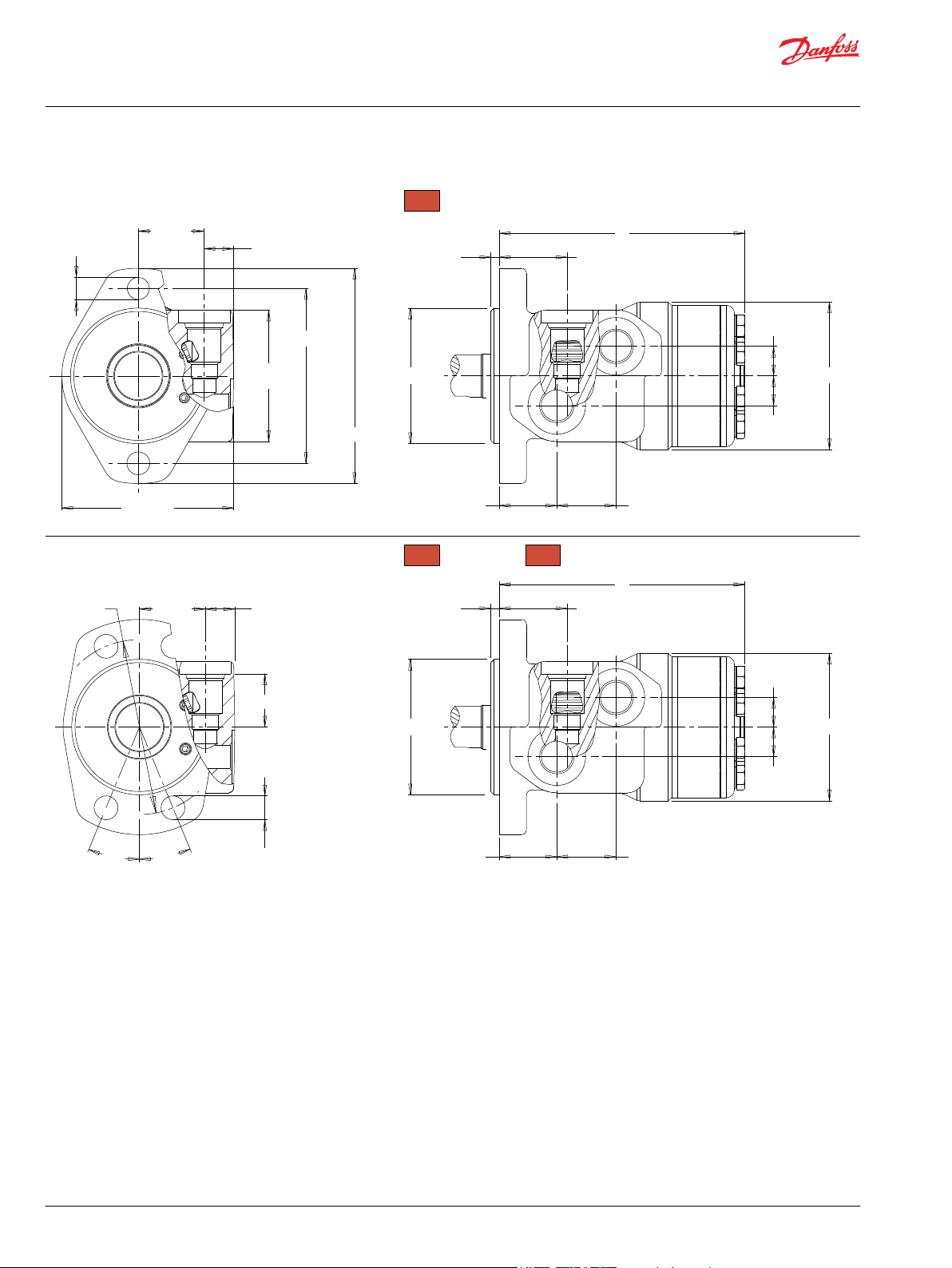
40 [1.57]
19 [.74]
13.5 [.531]
105 [4.14]
106.4 [4.189]
131.9 [5.193] Max.
80.8 [3.181]
Max.
3 [.12]
40 [1.58]
90.8 [3.575] Max.
18 [.71]
46.2 [1.819]
36 [1.42]
D
18 [.71]
Ø 82.5 [3.248]
B
A
2-HOLE, SAE A MOUNT, OFFSET PORTS, VALVE CAVITY
A19
7/8-14 UNF
90.8 [3.575] Max.
18 [.71]
36 [1.42]
D
18 [.71]
Ø 82.5 [3.248]
B
A
22.5° 22.5°
106.4 [4.189] 40 [1.57]
32.4 [1.276]
13.5 [.531]
19 [.74]
A39 - 3.0 [.120]
AC2 - 8.0 [.310]
A39 - 40 [1.58]
AC2 - 35 [1.38]
A39 - 46.2 [1.819]
AC2 - 41.2 [1.619]
A39
7/8-14 UNF
AC2
G 1/2 (TP)
4-HOLE, MAGNETO MOUNT, OFFSET PORTS,
VALVE CAVITY
P109642
Technical Information
Orbital Motors Type WD, WP and WR
WP Product Line
50 | © Danfoss | December 2019 BC267362166283en-000201
Page 51

Ø82.5 [3.248]
3 [.12]
Ø44.4 [1.748]
E
96.6 [3.803]
3.4 [.132]
62.4 [2.457]
31.2 [1.228]
7.1 [.280]
B
A
82 [3.228]
F21, F26 - (4) 3/8-16 UNC, Min. Depth 12 [.47]
G24, G28 - (4) M10 x 1.5, Min. Depth 12 [.47]
4-HOLE, SQUARE MOUNT, ALIGNED END PORTS
F21
7/8-14 UNF
G28
G 1/2
F26
3/4-16 UNF
G24
M22 x 1.5
13.5 [.531]
106,4 [4.189]
131.9 [5.193] Max.
E
Ø82.5 [3.248]
62.4 [2.457]
31.2 [1.228]
96.6 [3.803]
3.4 [.132]
7.1 [.280]
B
A
A06, A08 - 3 [.120]
AP6, AP8 - 8 [.310]
2-HOLE, SAE A MOUNT, ALIGNED END PORTS
A06
3/4-16 UNF
AP8
G 1/2 (TP)
A08
G 1/2
AP6
3/4-16 UNF (TP)
P109643
Technical Information
Orbital Motors Type WD, WP and WR
WP Product Line
155/156 Series Technical Data
Allowable Shaft Load / Bearing Curve
The bearing curve below represents the side load capacity of the motor at the centerline of the key for
various motor speeds. Operating conditions within the shaded area will maintain acceptable oil film
lubrication with recommended fluids. Operating conditions outside the shaded area are susceptible to
motor failure due to oil starvation and/or excessive heat generation. Fluids with low lubricity or low
viscosity may require the maximum load and speed ratings to be derated to provide acceptable motor
life and performance.
©
Danfoss | December 2019 BC267362166283en-000201 | 51
Page 52

6000 [1350]
8000 [1800]
N [lbf]
4000 [900]
2000 [450]
0 600 rpm700500400300200100
P109352
276 [4000]
207 [3000]
69 [1000]
138 [2000]
bar [psi]
0 1000900 rpm600 800700500400300200100
Continuous
Intermittent
P109353
P109354
Technical Information
Orbital Motors Type WD, WP and WR
WP Product Line
Permissible Shaft Seal Pressure
The curve below represents allowable seal pressure at various speeds. Operation in the gray area results
in maintaining the rated life of the shaft seal. Actual shaft seal pressure depends on motor configuration.
With check valves and drain connection, the shaft seal pressure equals pressure in the drain line. With
check valves and no drain connection, shaft seal pressure is identical to output pressure. No check valves
and no drain connection, the shaft seal pressure is identical to the average value of input and output
pressure.
52 | © Danfoss | December 2019 BC267362166283en-000201
Page 53

445 daN [1000 lb]
445 daN [1000 lb]
P109355
Technical Information
Orbital Motors Type WD, WP and WR
WP Product Line
Thrust Load
Length and Weight Charts
The overall motor weights listed in each chart were calculated using the heaviest of the housing options
associated with that mounting flange to end of motor dimension. 155 & 156 series motor weights can
vary ± 0.5 kg [1 lb] depending on model configurations such as housing, shaft, endcover, options etc.
Dimension D is the overall motor length from the rear of the motor to the mounting flange surface and is
referenced on detailed housing drawings listed in 155/156 Series Housings on page 45.
Dimension D
# 3 mm Pilot 8 mm Pilot Weight
mm [in] mm [in] kg [lb]
025 133 [5.24] 128 [5.04] 6.3 [13.9]
032 134 [5.28] 129 [5.08] 6.4 [14.1]
040 136 [5.34] 131 [5.16] 6.5 [14.2]
050 136 [5.34] 131 [5.16] 6.5 [14.2]
060 137 [5.40] 132 [5.20] 6.5 [14.3]
080 139 [5.49] 134 [5.28] 6.6 [14.5]
100 142 [5.59] 137 [5.39] 6.7 [14.7]
125 146 [5.74] 141 [5.55] 6.8 [14.9]
160 150 [5.90] 145 [5.71] 6.9 [15.2]
200 155 [6.10] 150 [5.91] 7.1 [15.6]
250 162 [6.36] 157 [6.18] 7.3 [16.1]
315 170 [6.69] 165 [6.50] 7.6 [16.7]
400 181 [7.13] 176 [6.93] 7.9 [17.5]
Dimension E is the overall motor length from the rear of the motor to the mounting flange surface and is
referenced on detailed housing drawings listed in 155/156 Series Housings on page 45.
Dimension E
# 3 mm Pilot 8 mm Pilot Weight
025 144 [5.67] 139 [5.47] 5.9 [13.0]
032 145 [5.71] 140 [5.51] 6.0 [13.2]
040 146 [5.75] 141 [5.55] 6.1 [13.4]
©
Danfoss | December 2019 BC267362166283en-000201 | 53
mm [in] mm [in] kg [lb]
Page 54

Technical Information
Orbital Motors Type WD, WP and WR
WP Product Line
Dimension E (continued)
# 3 mm Pilot 8 mm Pilot Weight
050 146 [5.75] 141 [5.55] 6.1 [13.4]
060 148 [5.83] 143 [5.63] 6.1 [13.4]
080 150 [5.91] 145 [5.71] 6.2 [13.6]
100 153 [6.02] 148 [5.83] 6.3 [13.9]
125 157 [6.18] 152 [5.98] 6.4 [14.1]
160 161 [6.33] 156 [6.14] 6.5 [14.3]
200 166 [6.54] 161 [6.34] 6.7 [14.7]
250 173 [6.81] 168 [6.61] 6.9 [15.2]
315 181 [7.13] 176 [6.93] 7.2 [15.8]
400 192 [7.56] 187 [7.36] 7.5 [16.5]
mm [in] mm [in] kg [lb]
54 | © Danfoss | December 2019 BC267362166283en-000201
Page 55
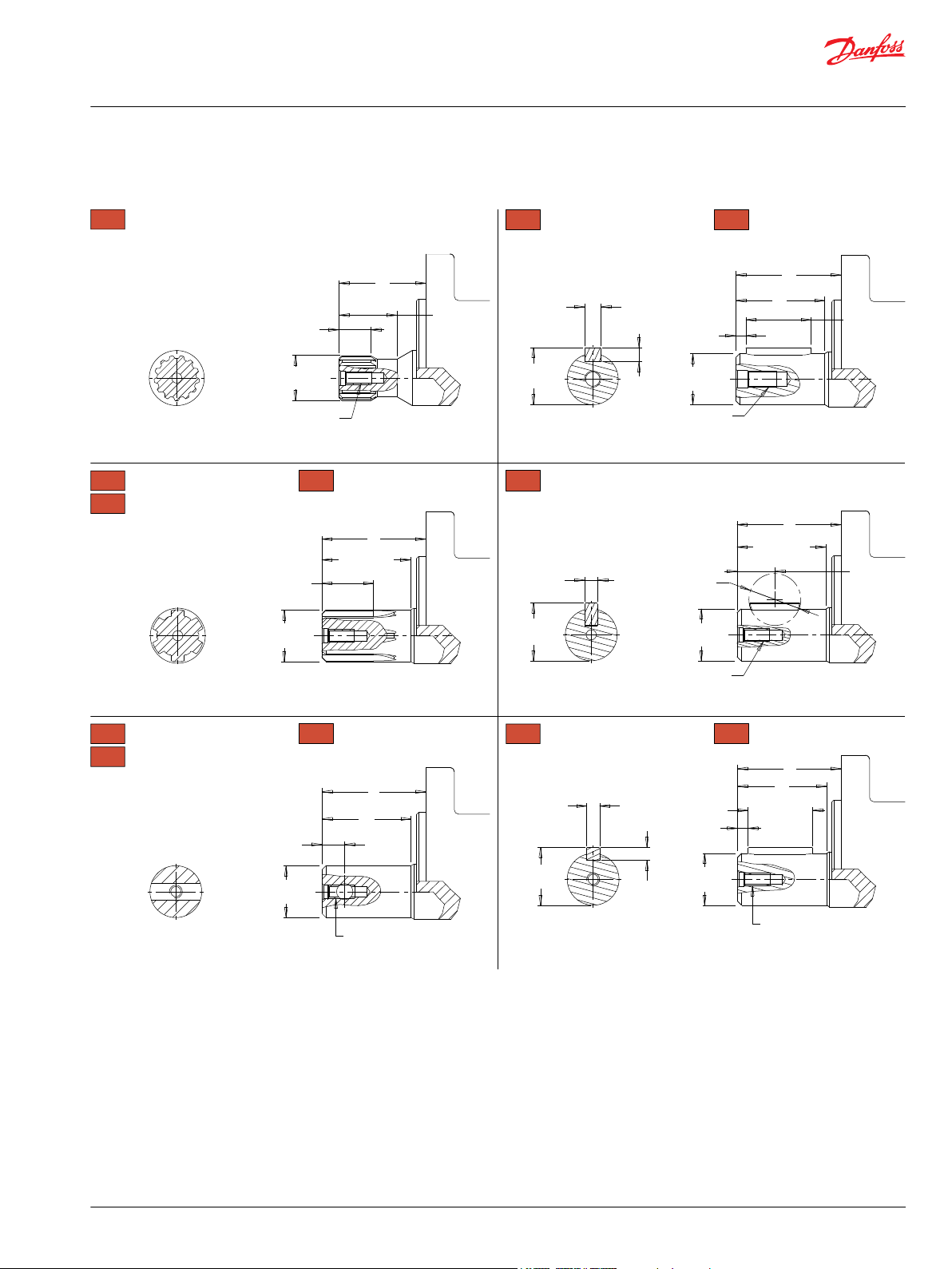
P109364
5 [.20]
31.75 [1.250]
31.45 [1.238]
7.95 [.313]
7.93 [.312]
28.30 [1.114]
27.89 [1.098]
25.4 [1.000]
M8 X 1.25,
Min. Depth 20 [.79]
19.1 [.761]
18.0 [.709]
14.7 [.579]
25.4 [1.000]
25.4 [.999]
27.98 [1.102]
27.70 [1.091]
6.98 [.275]
6.90 [.271]
Ø25.02 [.985]
Ø25.00 [.984]
6.38 [.251]
6.35 [.250]
Ø 25.4 [1.000]
Ø 25.1 [.990]
Ø22.3 [.878]
Ø22.2 [.874]
Ø25.4 [.998]
Ø25.3 [.996]
39.2 [1.543]
39.9 [1.571]
32.7 [1.287]
F
F
F
F
01
7/8” 13 Tooth Spline
Max. Torque: 170 Nm [1500 lb-in] Max. Torque: 655 Nm [5800 lb-in]
02
1” 6B Spline, 1/4-20 Tap
Max. Torque: 678 Nm [6000 lb-in]
04
1” 6B Spline, M8x1.25 Tap
F3
1” 6B Spline, M8x1.25 Tap
B1
1” Straight, Woodruff Key
Max. Torque: 655 Nm [5800 lb-in]
12
25mm Straight
16
25mm Straight Extended
F
2
31.75 [1.250]
31.45 [1.238]
5 [.20]
F
25.4 [1.000]
25.4 [0.999]
6.35 [.250]
6.3 [.248]
6.35 [.250]
6.3 [.248]
28.15 [1.122]
27.95 [1.100]
1/4-20 UNC,
Min. Depth 16 [.63]
Max. Torque: 655 Nm [5800 lb-in]
10
1” Straight
15
1” Straight Extended
F
2
1/4-20 UNC,
Min. Depth 16 [.63]
25.4 [1.000]
25.4 [0.999]
1/4-20 UNC, Min. Depth 16 [.63]
F
F
2
05
1” - 9.5 [.375] Pinhole
Max. Torque: 678 Nm [6000 lb-in]
53
1” - 10.3 [.406] Pinhole
66
1” - 8.0 [.315] Pinhole
05, 53 - 16 [.62]
66 - 11 [.44]
1/4-20 UNC,
Min. Depth 16 [.63]
F3 - 6B Spline
B.S. 2059 Standard
02, 04 - 6B Spline
SAE J499 Standard
Technical Information
Orbital Motors Type WD, WP and WR
WP Product Line
155/156 Series Shafts
Mounting / Shaft Length Chart
Dimension F is the overall distance from the motor mounting surface to the end of the shaft.
Additional shaft length information, if necessary, is noted as F2 and does not increase or decrease the
listed F dimensions in this chart. The overall shaft lengths are already factored into the overall distance
©
Danfoss | December 2019 BC267362166283en-000201 | 55
from the mounting surface to the end of the shaft.
Page 56

Technical Information
Orbital Motors Type WD, WP and WR
WP Product Line
Dimension F
# 3 mm Pilot 8 mm Pilot F
01 43.3 [1.705] 48.3 [1.902] N/A
02 45.3 [1.783] 50.3 [1.980] N/A
04 45.3 [1.783] 50.3 [1.980] N/A
05 45.3 [1.783] 50.3 [1.980] 39.2 [1.543]
10 45.3 [1.783] 50.3 [1.980] 39.2 [1.543]
12 50.3 [1.980] 55.3 [2.177] 44.2 [1.740]
15 62.1 [2.445] 67.1 [2.642] 56.0 [2.205]
16 62.6 [2.464] 67.6 [2.661] 56.5 [2.225]
53 45.3 [1.783] 50.3 [1.980] 39.2 [1.543]
66 50.3 [1.980] 55.3 [2.177] 44.2 [1.740]
B1 45.3 [1.783] 50.3 [1.980] N/A
2
mm [in] mm [in] mm [in]
56 | © Danfoss | December 2019 BC267362166283en-000201
Page 57

Technical Information
Orbital Motors Type WD, WP and WR
WP Product Line
155/156 Order Codes
©
Danfoss | December 2019 BC267362166283en-000201 | 57
Page 58
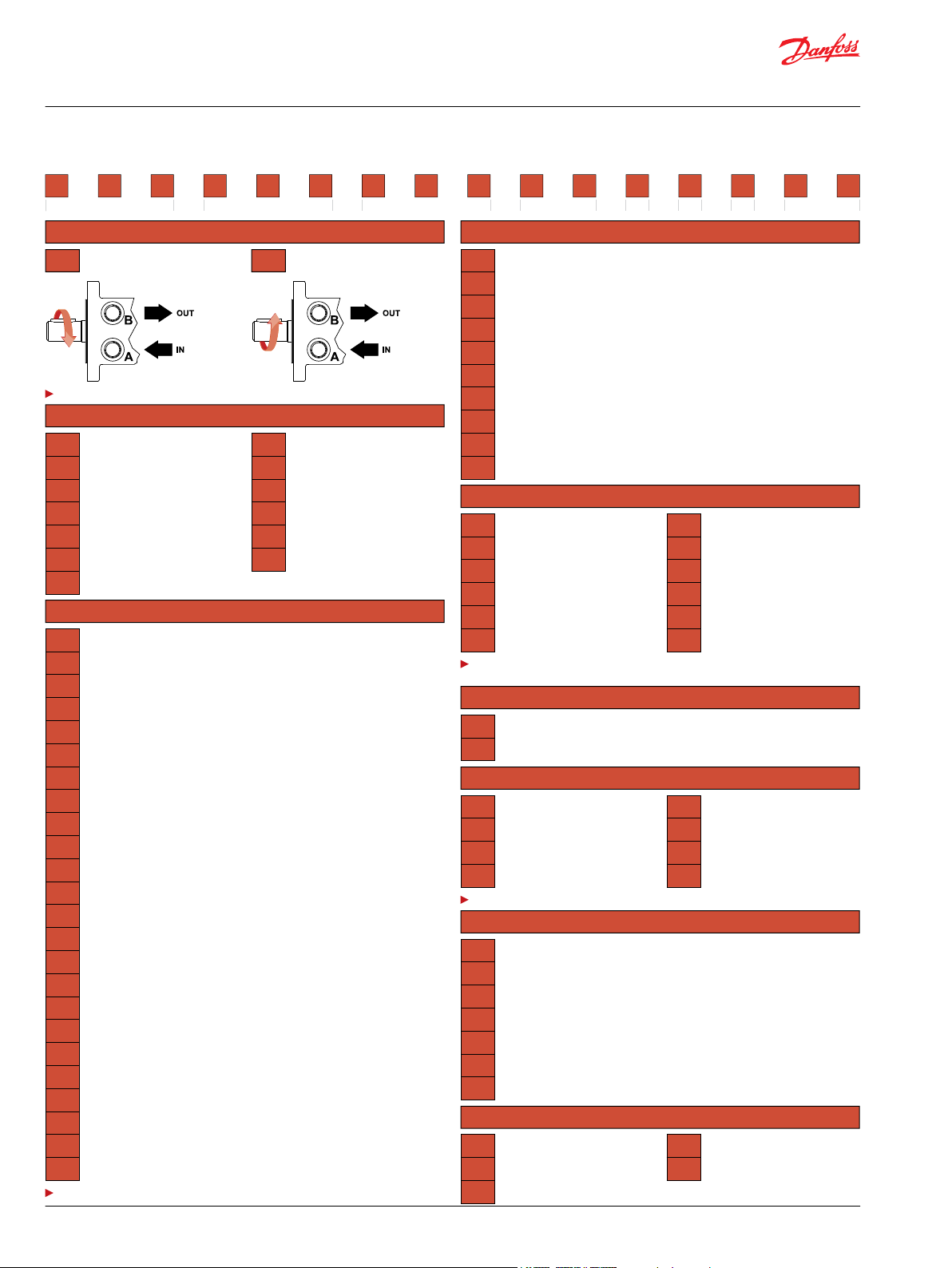
1 2 3 4 5 6 7 8
25 cm3/rev [1.5 in3/rev]
32 cm3/rev [2.0 in3/rev]
40 cm3/rev [2.5 in3/rev]
50 cm3/rev [3.0 in3/rev]
59 cm3/rev [3.6 in3/rev]
78 cm3/rev [4.8 in3/rev]
96 cm3/rev [5.9 in3/rev]
Standard Rotation Reverse Rotation
The 155 & 156 series are bi-directional.
125 cm3/rev [7.6 in3/rev]
154 cm3/rev [9.4 in3/rev]
190 cm3/rev [11.6 in3/rev]
240 cm3/rev [14.6 in3/rev]
303 cm3/rev [18.5 in3/rev]
388 cm3/rev [23.7 in3/rev]
2-Hole, SAE A Mount, Aligned End Ports, 3/4-16 UNF
2-Hole, SAE A Mount, Aligned End Ports, G 1/2
2-Hole, SAE A Mount, Aligned End Ports, 3/4-16 UNF (TP)
2-Hole, SAE A Mount, Aligned End Ports, G 1/2 (TP)
2-Hole, SAE A Mount, Aligned Ports, 1/2-14 NPT
2-Hole, SAE A Mount, Aligned Ports, 7/8-14 UNF
2-Hole, SAE A Mount, Offset Ports, G 1/2
2-Hole, SAE A Mount, Offset Manifold Ports, G 1/2
2-Hole, SAE A Mount, Aligned Manifold Ports, 1/2” Drilled
2-Hole, SAE A Mount, Aligned Ports, G 1/2
2-Hole, SAE A Mount, Offset Ports, Valve Cavity 7/8-14 UNF
4-Hole, Magneto Mount, Aligned Ports, 1/2-14 NPT
4-Hole, Magneto Mount, Aligned Ports, 7/8-14 UNF
4-Hole, Magneto Mount, Offset Ports, G 1/2
4-Hole, Magneto Mount, Aligned Manifold Ports, 1/2” Drilled
4-Hole, Magneto Mount, Offset Ports, Valve Cavity 7/8-14 UNF
4-Hole, Magneto Mount, Offset Manifold Ports, 7/8-14 UNF
2-Hole, SAE A Mount, Offset Ports, G 1/2 (TP)
2-Hole, SAE A Mount, Offset Manifold Ports, G 1/2 (TP)
2-Hole, SAE A Mount, Aligned Ports, G 1/2 (TP)
2-Hole, SAE A Mount, Offset Ports, 7/8-14 UNF (TP)
4-Hole, Magneto Mount, Offset Ports, G 1/2 (TP)
4-Hole, Magneto Mount, Offset Manifold Ports, G 1/2 (TP)
4-Hole, Magneto Mount, Aligned Manifold Ports, 1/2” Drilled (TP)
7/8” 13 Tooth Spline
1” 6B Spline, 1/4-20 Tap
1” 6B Spline, M8x1.25 Tap
1” - 9.5 [.375] Pinhole
1” Straight
25mm Straight
1” Straight Extended
25mm Straight Extended
1” - 10.3 [.406] Pinhole
1” - 8.0 [.315] Pinhole
1” Straight, Woodruff Key
1” 6B Spline, M8x1.25 Tap
Black
Black, Unpainted Mounting Surface
Standard
Lock Nut
Solid Hex Nut
Speed Sensor, Dual, 4-Pin Male Weatherpack Connector
Speed Sensor, Dual, 4-Pin M12 Male Connector
Speed Sensor, Single, 3-Pin Male Weatherpack Connector
Speed Sensor, Single, 4-Pin M12 Male Connector
None
Freeturning Rotor
Slinger Seal
The 15 & 16 extended shafts are designed for use with one of the speed sensor options listed in
STEP 7.
(TP) - Tall pilot. Speed sensor option is not available on tall pilot housings.
None
Valve Cavity Only
69 bar [1000 psi] Relief
86 bar [1250 psi] Relief
104 bar [1500 psi] Relief
121 bar [1750 psi] Relief
138 bar [2000 psi] Relief
173 bar [2500 psi] Relief
Valve cavity is only available on the A19, A39 & AC2 housings.
4-Hole, Magneto Mount, Aligned Ports, G 1/2 (TP)
4-Hole, Square Mount, Aligned End Ports, 7/8-14 UNF
4-Hole, Square Mount, Aligned End Ports, 3/4-16 UNF
4-Hole, Square Mount, Aligned Ports, 1/2-14 NPT
4-Hole, Square Mount, Aligned Ports, 7/8-14 UNF
4-Hole, Square Mount, Aligned Manifold Ports, 1/2” Drilled
4-Hole, Square Mount, Aligned Ports, G 1/2
2-Hole, SAE A Mount, Aligned Manifold Ports, 1/2” Drilled
4-Hole, Square Mount, Aligned End Ports, M22 x 1.5
4-Hole, Square Mount, Aligned End Ports, G 1/2
Groove In Mounting Flange
No Check Valves Installed
155
1. CHOOSE SERIES DESIGNATION
2. SELECT A DISPLACEMENT OPTION
025
032
040
050
060
080
100
125
160
200
250
315
400
3. SELECT A MOUNT & PORT OPTION
3. SELECT A MOUNT & PORT OPTION
A06
A08
AP6
AP8
A10
A11
A12
A13
A17
A18
A19
A30
A31
A32
A37
A39
A3D
A62
A63
A68
A69
AC2
AC3
AC7
4. SELECT A SHAFT OPTION
01
02
04
05
10
12
AC8
F21
F26
F30
F31
F37
F38
G17
G24
G28
15
16
53
66
B1
F3
5. SELECT A PAINT OPTION
A
B
6. SELECT A VALVE CAVITY / CARTRIDGE OPTION
7. SELECT AN ADD-ON OPTION
A
B
C
W
X
Y
Z
8. SELECT A MISCELLANEOUS OPTION
AA
AC
BE
156
A
B
C
D
E
F
G
J
DS
FB
P109358
Technical Information
Orbital Motors Type WD, WP and WR
WP Product Line
58 | © Danfoss | December 2019 BC267362166283en-000201
Page 59

Technical Information
Orbital Motors Type WD, WP and WR
WP Product Line
©
Danfoss | December 2019 BC267362166283en-000201 | 59
Page 60

B
A
86 [3.39]
45°
H
19 [.75]
69 [2.72]
38 [1.50]
7 [.276]
18.5 [.73]
18.5 [.73]
79.2 [3.118]
78.8 [3.102]
80.00 [3.150]
79.95 [3.148]
103 [4.055]
(4) 3/8-16 UNC, 20 [.79] Min. Deep
(4) M10x1.5, 20 [.79] Min. Deep
W31 W38 -
106 [4.17]
55 [2.17]
102 [4.00]
131.9 [5.193]
Max.
Ø13.7 [.539]
Ø13.5 [.531]
102 [4.02]
55 [2.17]
Ø106.4 [4.189]
39 [1.52]
Ø90.8 [3.575]
Max.
18 [.71]
18 [.71]
20 [.79]
20 [.79]
G
8.3 [.327]
7.7 [.303]
39 [1.52]
20 [.79]
20 [.79]
A63 -
A6D -
M8x1.25,
Min. Depth 12 [.47]
5/16-18 UNC,
Min. Depth 12 [.47]
Ø82.55 [3.248]
Ø82.45 [3.246]
A63
G 1/2
2-HOLE, SAE A MOUNT, OFFSET MANIFOLD PORTS
A6D 7/8-14 UNF
4-HOLE, WHEEL MOUNT, ALIGNED PORTS
W31
7/8-14 UNF
W38
G 1/2
P109351
Technical Information
Orbital Motors Type WD, WP and WR
WP Product Line
WP 157 and 158 Series
WP 157 and 158 Series Housings
Dimensions shown are without paint. Paint thickness can be up to 0.13 [.005].
Dimensions are charted in WP 157 and 158 Series Technical Information on page 60.
WP 157 and 158 Series Technical Information
Allowable Shaft Load / Bearing Curve
The bearing curve represents allowable bearing loads based on ISO 281 bearing capacity for an L10 life of
2,000 hours at 100 rpm. Radial loads for speeds other than 100 rpm may be calculated using the
multiplication factor table in Vehicle Drive Calculations on page 9.
60 | © Danfoss | December 2019 BC267362166283en-000201
Page 61

2800
SAE A MOUNT
lb
2400
2000
1600
1200
800
400
1200
daN
200
1000
800
600
400
in-4 3210-1-2-3
mm50 750-50 25-25-75-100
445 daN [1000 lb]
335 daN [750 lb]
SHAFT
BEARING
P109359
2800
WHEEL MOUNT
lb
2400
2000
1600
1200
800
400
1200
daN
200
1000
800
600
400
in-2 543210-1
mm100 125500 7525-25-50
445 daN [1000 lb]
335 daN [750 lb]
SHAFT
BEARING
P109361
Technical Information
Orbital Motors Type WD, WP and WR
WP Product Line
SAE A Mount
Wheel Mount
Length and Weight Chart
Dimension G is the overall motor length from the rear of the motor to the mounting flange surface.
©
Danfoss | December 2019 BC267362166283en-000201 | 61
Page 62

Technical Information
Orbital Motors Type WD, WP and WR
WP Product Line
Dimension G
# Length Weight
025 133 [5.24] 6.0 [13.3]
032 134 [5.28] 6.1 [13.4]
040 136 [5.33] 6.1 [13.5]
050 136 [5.33] 6.1 [13.5]
060 137 [5.39] 6.2 [13.6]
080 139 [5.48] 6.2 [13.6]
100 142 [5.59] 6.3 [13.9]
125 146 [5.74] 6.4 [14.2]
160 150 [5.89] 6.6 [14.5]
200 155 [6.09] 6.7 [14.9]
250 161 [6.35] 7.0 [15.3]
315 170 [6.69] 7.2 [15.9]
400 181 [7.13] 7.6 [16.8]
mm [in] kg [lb]
Dimension H is the overall motor length from the rear of the motor to the mounting flange surface.
Dimension H
# Length Weight
mm [in] kg [lb]
025 72 [2.83] 6.4 [14.1]
032 73 [2.87] 6.5 [14.4]
040 75 [2.95] 6.6 [14.5]
050 75 [2.95] 6.6 [14.5]
060 76 [2.99] 6.7 [14.8]
080 78 [3.07] 6.8 [15.0]
100 81 [3.19] 6.9 [15.2]
125 85 [3.35] 7.0 [15.5]
160 89 [3.50] 7.1 [15.6]
200 94 [3.70] 7.2 [15.9]
250 100 [3.94] 7.4 [16.4]
315 109 [4.29] 7.7 [17.0]
400 120 [4.72] 8.1 [17.8]
WP 157 and 158 Series Shafts
Mounting / Shaft Length Chart
Dimension J is the overall distance from the motor mounting surface to the end of the shaft.
Dimension J
# SAE and A Mounts Wheel Mounts
mm [in] mm [in]
10 55 [2.18] 116 [4.57]
11 55 [2.18] 116 [4.57]
62 | © Danfoss | December 2019 BC267362166283en-000201
Page 63
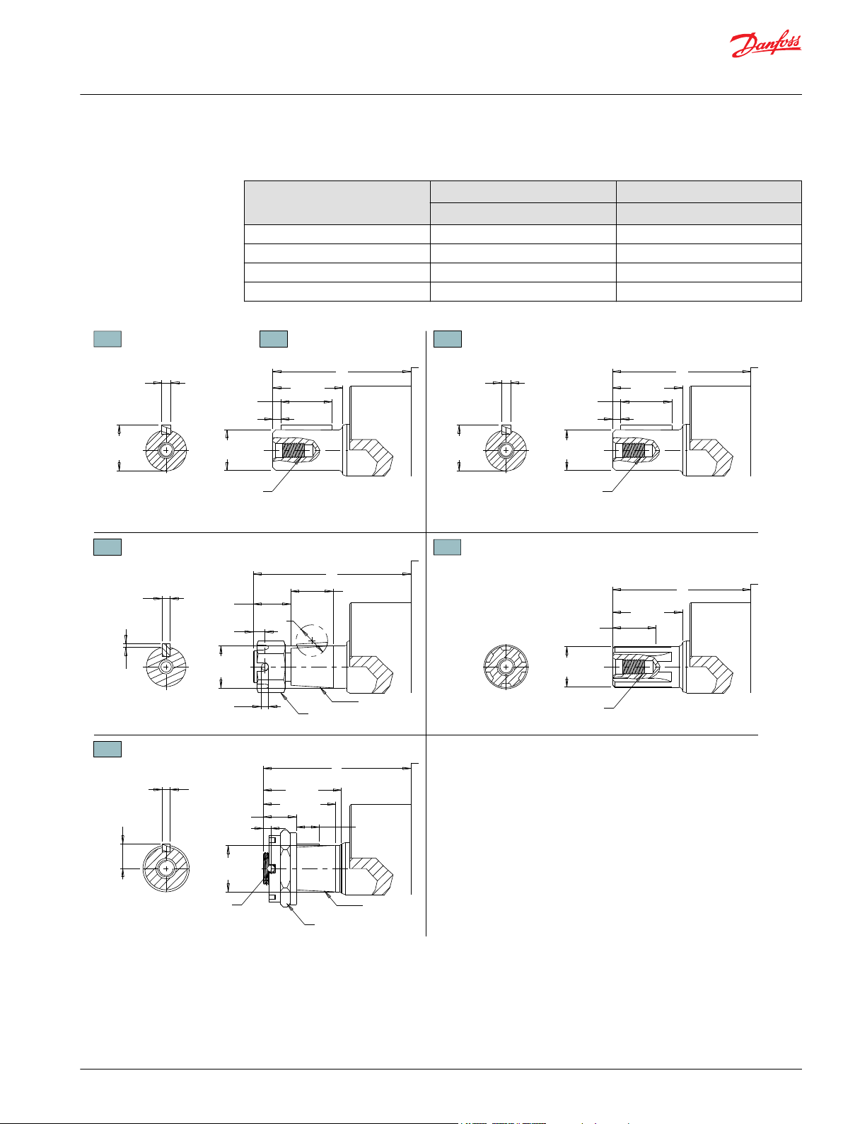
3 [.12]
31.7 [1.249]
31.4 [1.236]
10 - Min. Depth 16 [.63]
11 - Min. Depth 18 [.71]
J
43 [1.69]
43 [1.69]
8.0 [.313]
7.9 [.312]
28.0 [1.102]
27.7 [1.091]
25.0 [.985]
25.0 [.984]
5 [.20]
31.7 [1.249]
31.4 [1.236]
M8x1.25
Min. Depth 18 [.71]
J
43 [1.69]
J
J
48 [1.89]
44.5 [1.75]
20.5 [.81]
5 [.19]
25.4 [1.000]
14 [.55]
1:10 Taper
M20x1.5 Slotted Hex Nut
Ø 4.5 [.18] Thru.
6.4 [.251]
6.4 [.250]
28.2 [1.110]
28.0 [1.101]
6B Spline
B.S. 2059 Standard
25.4 [1.000]
25.4 [0.999]
25.4 [.998]
25.3 [.996]
5.0 [.197]
5.0 [.196]
15.3 [.602]
15.2 [.600]
28.57 [1.125]
28.56 [1.124]
M8x1.25
Min. Depth 18 [.71]
7 [.28]
4 [.16]
1:8 Taper
3/4-20 UNEF
Slotted Hex Nut
2.5 [.097]
2.2 [.087]
25 [1.00]
25.4 [1.000]
25.4 [.999]
J
23 [.89]
19 [.75]
4.8 [.189]
4.8 [.188]
Max. Torque: 655 Nm [5800 lb-in] Max. Torque: 655 Nm [5800 lb-in]
Max. Torque: 678 Nm [6000 lb-in]
Max. Torque: 655 Nm [5800 lb-in]
F3 1” 6B Spline
N9
28.5mm Tapered
10
1” Straight, 1/4-20 Tap
11
1” Straight, M8x1.25 Tap
12 25mm Straight
Max. Torque: 655 Nm [5800 lb-in]
13
1” Tapered
P109397
Technical Information
Orbital Motors Type WD, WP and WR
WP Product Line
Dimension J (continued)
# SAE and A Mounts Wheel Mounts
12 55 [2.18] 116 [4.57]
13 66 [2.60] 127 [5.00]
F3 55 [2.18] 116 [4.57]
N9 58 [2.29] 119 [4.69]
mm [in] mm [in]
©
Danfoss | December 2019 BC267362166283en-000201 | 63
Page 64

1 2 3 4 5 6 7 8
25 cm3/rev [1.5 in3/rev]
32 cm3/rev [2.0 in3/rev]
40 cm3/rev [2.5 in3/rev]
50 cm3/rev [3.0 in3/rev]
59 cm3/rev [3.6 in3/rev]
78 cm3/rev [4.8 in3/rev]
96 cm3/rev [5.9 in3/rev]
Clockwise Rotation Counterclockwise Rotation
The 157 & 158 series are bi-directional. Reversing the inlet hose will reverse shaft rotation.
125 cm3/rev [7.6 in3/rev]
154 cm3/rev [9.4 in3/rev]
190 cm3/rev [11.6 in3/rev]
240 cm3/rev [14.6 in3/rev]
303 cm3/rev [18.5 in3/rev]
388 cm3/rev [23.7 in3/rev]
2-Hole, SAE A Mount, Offset Manifold Ports, G 1/2
2-Hole, SAE A Mount, Offset Manifold Ports, 7/8-14 UNF
4-Hole, Wheel Mount, Aligned Ports, 7/8-14 UNF
4-Hole, Wheel Mount, Aligned Ports, G 1/2
1” Straight, 1/4-20 Tap
1” Straight, M8x1.25 Tap
25mm Straight
1” Tapered
1” 6B Spline
28.5mm Tapered
Black
Black, Unpainted Mounting Surface
Standard
None
Freeturning Rotor
None
157
1. CHOOSE SERIES DESIGNATION
2. SELECT A DISPLACEMENT OPTION
025
032
040
050
060
080
100
125
160
200
250
315
400
3. SELECT A MOUNT & PORT OPTION
A63
A6D
W31
W38
4. SELECT A SHAFT OPTION
10
11
12
13
F3
N9
5. SELECT A PAINT OPTION
A
B
6. SELECT A VALVE CAVITY / CARTRIDGE OPTION
7. SELECT AN ADD-ON OPTION
A
8. SELECT A MISCELLANEOUS OPTION
AA
AC
158
A
P109363
Technical Information
Orbital Motors Type WD, WP and WR
WP Product Line
WP 157 and 158 Series Ordering Information
64 | © Danfoss | December 2019 BC267362166283en-000201
Page 65

P109365
P109366
Technical Information
Orbital Motors Type WD, WP and WR
WR Product Line
WR Product Line Introduction
Overview
The WR Series motors incorporate the latest advances for smooth performance, efficiency and durability.
Featuring an optimized Roller Stator® geometry with seven precision rollers to eliminate sliding friction
and provide rolling contact between the rotor and stator, thus increasing motor efficiency. A three-zone
spool valve, integral check valves and a provision for a case drain reduce pressure on internal seals to
improve product life. A wide variety of mounting, shaft, motor displacement and porting options are
available to meet all application needs.
Features / Benefits
•
A variety of mounts and shafts provides flexibility in application design.
•
A high pressure shaft seal offers superior seal life and performance.
•
The spool valve design gives superior performance and smooth operation over a wide speed and
torque range.
•
Built-in check valves (not shown) in the housing offer versatility and increased seal life.
•
Optimized Roller Stator® geometry provides a smooth running high efficient product.
Typical Applications
conveyors, carwashes, positioners, light-duty wheel drives, sweepers, food processing, grain augers,
spreaders, feed rollers, screw drives, brush drives and more
Series Descriptions
251/252 - Hydraulic Motor
Standard
255/256 - Hydraulic Motor
Standard
©
Danfoss | December 2019 BC267362166283en-000201 | 65
Page 66

43
95
188
365
560
728
942
1116
40
91
180
355
548
716
936
1113
1316
1515
35
82
170
343
532
706
927
1100
1301
1497
29
73
160
324
515
684
918
1082
1278
1469
24
62
144
312
502
667
904
1056
1253
1442
51
137
295
485
648
890
1028
1230
1415
126
293
471
634
874
1004
1206
1399
115
275
451
629
852
976
1184
1378
102
257
432
618
835
952
1154
1355
88
237
444
601
812
916
1116
1330
198
398
545
743
870
1078
1298
[80]
[88]
[80]
[62]
[53]
[53]
[44]
[27]
9
10
9
7
6
6
5
3
[177]
[186]
[168]
[159]
[150]
[142]
[124]
[115]
[88]
[71]
20
21
19
18
17
16
14
13
10
8
[283]
[265]
[248]
[239]
[230]
[221]
[195]
[186]
[177]
[168]
32
30
28
27
26
25
22
21
20
19
[354]
[372]
[363]
[354]
[345]
[327]
[310]
[301]
[274]
[257]
40
42
41
40
39
37
35
34
31
29
[327]
[460]
[451]
[434]
[425]
[416]
[398]
[381]
[345]
[336]
37
52
51
49
48
47
45
43
39
38
[549]
[566]
[549]
[540]
[522]
[504]
[487]
[460]
[434]
62
64
62
61
59
57
55
52
49
[637]
[646]
[619]
[602]
[602]
[593]
[558]
[531]
72
73
70
68
68
67
63
60
[699]
[735]
[726]
[717]
[690]
[681]
[664]
[655]
79
83
82
81
78
77
75
74
[788]
[823]
[796]
[779]
[761]
[743]
[726]
[708]
89
93
90
88
86
84
82
80
[876]
[903]
[894]
[876]
[858]
[841]
[823]
[796]
99
102
101
99
97
95
93
90
[1071]
[1080]
[1088]
[1044]
[1027]
[1018]
[1000]
121
122
123
118
116
115
113
Torque - Nm [lb-in], Speed rpm
Flow - lpm [gpm]
17 [250] 35 [500] 52 [750] 69 [1000] 86 [1250] 104 [1500] 121 [1750] 138 [2000] 155 [2250] 172 [2500] 207 [3000]
11 [97] 22 [195] 34 [301] 45 [398] 56 [496] 67 [593] 78 [690] 90 [796] 101 [894] 112 [991] 132 [1167]
Theoretical Torque - Nm [lb-in]
Max.
Inter.
Max.
Cont.
040
2 [0.5]
4 [1]
8 [2]
15 [4]
23 [6]
30 [8]
38 [10]
45 [12]
53 [14]
61 [16]
50
100
199
373
572
746
945
1119
1318
1517
Theoretical rpm
Overall Efficiency -
70 - 100%
40 - 69%
0 - 39%
Intermittent Ratings - 10% of Operation
Displacement tested at 54°C [129°F] with an oil viscosity of 46cSt [213 SUS]
Max. Inter.Max. Cont.Pressure - bar [psi]
40 cm3 [2.5 in3] / rev
mm [in]
Rotor
Width
8.1
[.317]
P109367
Technical Information
Orbital Motors Type WD, WP and WR
WR Product Line
Specifications
Performance data is typical. Performance of production units varies slightly from one motor to another.
Running at intermittent ratings should not exceed 10% of every minute of operation.
CODE
Displacem
ent
cm3 [in3]
Max. Speed
rpm
Max. Flow
lpm [gpm]
Max. Torque
Nm [lb-in]
Max. Pressure
bar [psi]
cont. inter. cont. inter. cont. inter. cont. inter. peak
040 40 [2.5] 1116 1515 45 [12] 61 [16] 93 [823] 123 [1088] 155 [2250] 207 [3000] 224 [3250]
050 50 [3.1] 1058 1220 53 [14] 61 [16] 111 [982] 149 [1319] 155 [2250] 207 [3000] 224 [3250]
060 59 [3.6] 890 1142 53 [14] 68 [18] 138 [1221] 172 [1522] 155 [2250] 207 [3000] 224 [3250]
070 71 [4.3] 865 1078 61 [16] 76 [20] 176 [1558] 207 [1832] 172 [2500] 207 [3000] 241 [3500]
080 79 [4.9] 759 957 61 [16] 76 [20] 202 [1788] 243 [2150] 172 [2500] 207 [3000] 241 [3500]
090 88 [5.4] 691 864 61 [16] 76 [20] 222 [1965] 263 [2327] 172 [2500] 207 [3000] 241 [3500]
100 100 [6.1] 610 760 61 [16] 76 [20] 246 [2177] 289 [2558] 172 [2500] 207 [3000] 241 [3500]
115 113 [6.9] 539 672 61 [16] 76 [20] 284 [2513] 327 [2894] 172 [2500] 207 [3000] 241 [3500]
130 129 [7.9] 472 588 61 [16] 76 [20] 316 [2797] 375 [3319] 172 [2500] 207 [3000] 241 [3500]
160 160 [9.8] 379 469 61 [16] 76 [20] 400 [3540] 454 [4018] 172 [2500] 207 [3000] 241 [3500]
200 198 [12.1] 308 384 61 [16] 76 [20] 462 [4088] 544 [4814] 172 [2500] 207 [3000] 241 [3500]
240 236 [14.4] 249 315 61 [16] 76 [20] 548 [4850] 642 [5682] 172 [2500] 207 [3000] 224 [3250]
250 250 [15.3] 250 300 61 [16] 76 [20] 561 [4965] 624 [5522] 172 [2500] 207 [3000] 224 [3250]
290 291 [17.8] 210 256 61 [16] 76 [20] 526 [4655] 664 [5876] 138 [2000] 190 [2750] 207 [3000]
320 322 [19.6] 188 235 61 [16] 76 [20] 518 [4584] 690 [6106] 121 [1750] 172 [2500] 190 [2750]
400 400 [24.4] 152 190 61 [16] 76 [20] 551 [4873] 698 [6177] 104 [1500] 138 [2000] 155 [2250]
WR Displacement Performance
Performance data is typical. Performance of production units varies slightly from one motor to another.
Operating at maximum continuous pressure and maximum continuous flow simultaneously is not
recommended. For additional information on product testing please refer to Product Testing on page 7.
66 | © Danfoss | December 2019 BC267362166283en-000201
Page 67

77
155
295
452
594
754
896
75
152
291
447
589
749
892
1058
1220
74
150
283
434
577
736
875
1055
1216
69
142
272
430
566
728
873
1052
1212
63
132
267
416
546
716
861
1036
1210
52
124
248
402
528
699
843
998
1198
41
107
231
385
509
680
827
988
1160
36
91
215
368
489
664
812
960
1130
82
199
346
468
644
794
972
1112
182
324
448
624
776
904
1080
164
300
426
600
752
860
1032
[97]
[97]
[80]
[62]
[44]
[27]
[18]
11
11
9
7
5
3
2
[212]
[212]
[204]
[195]
[186]
[168]
[150]
[124]
[97]
24
24
23
22
21
19
17
14
11
[327]
[319]
[319]
[310]
[301]
[283]
[265]
[239]
[212]
37
36
36
35
34
32
30
27
24
[434]
[434]
[434]
[416]
[398]
[398]
[381]
[345]
[310]
49
49
49
47
45
45
43
39
35
[540]
[548]
[548]
[540]
[531]
[504]
[487]
[451]
[416]
61
62
62
61
60
57
55
51
47
[655]
[664]
[664]
[655]
[655]
[619]
[602]
[566]
[531]
74
75
75
74
74
70
68
64
60
[726]
[779]
[779]
[770]
[761]
[726]
[708]
[673]
[637]
82
88
88
87
86
82
80
76
72
[805]
[876]
[876]
[876]
[876]
[841]
[814]
[779]
[743]
91
99
99
99
99
95
92
88
84
[947]
[973]
982]
[982]
[947]
[929]
[885]
[850]
107
110
111
111
107
105
100
96
[1088]
[1097]
[1106]
[1062]
[1027]
[991]
[956]
123
124
125
120
116
112
108
[1301]
[1319]
[1310]
[1257]
[1221]
[1186]
[1150]
147
149
148
142
138
134
130
Torque - Nm [lb-in], Speed rpm
Flow - lpm [gpm]
17 [250] 35 [500] 52 [750] 69 [1000] 86 [1250] 104 [1500] 121 [1750] 138 [2000] 155 [2250] 172 [2500] 207 [3000]
14 [122] 27 [195] 41 [301] 55 [398] 69 [496] 82 [593] 96 [690] 110 [796] 124 [894] 137 [1215] 165 [1458]
Theoretical Torque - Nm [lb-in]
Max.
Inter.
Max.
Cont.
050
4 [1]
8 [2]
15 [4]
23 [6]
30 [8]
38 [10]
45 [12]
53 [14]
61 [16]
80
160
300
460
600
760
900
1060
1220
Theoretical rpm
Overall Efficiency -
70 - 100%
40 - 69%
0 - 39%
Intermittent Ratings - 10% of Operation
Displacement tested at 54°C [129°F] with an oil viscosity of 46cSt [213 SUS]
Max. Inter.Max. Cont.Pressure - bar [psi]
mm [in]
Rotor
Width
9.9
[.389]
50 cm3 [3.1 in3] / rev
P109368
28
60
134
250
384
502
635
755
890
22
56
129
245
380
496
632
748
888
1021
1142
15
50
125
240
376
494
629
745
884
1018
1140
12
44
118
232
370
490
628
741
880
1011
1129
33
113
225
364
485
619
735
874
1007
1112
16
107
217
356
478
611
729
865
1000
1097
97
208
345
468
598
718
852
993
1085
87
198
331
460
589
705
840
984
1074
73
185
318
450
578
688
831
974
1060
58
174
307
438
561
676
820
962
1044
50
168
298
431
513
659
802
956
1020
[106]
[115]
[124]
[106]
[97]
[89]
[80]
[71]
[53]
12
13
14
12
11
10
9
8
6
[230]
[257]
[274]
[266]
[266]
[257]
[248]
[212]
[204]
[150]
[89]
26
29
31
30
30
29
28
24
23
17
10
[301]
[372]
[407]
[398]
[389]
[381]
[372]
[345]
[336]
[257]
[230]
34
42
46
45
44
43
42
39
38
29
26
[398]
[496]
[513]
[531]
[522]
[513]
[487]
[460]
[425]
[389]
[354]
45
56
58
60
59
58
55
52
48
44
40
[549]
[655]
[664]
[655]
[637]
[620]
[611]
[575]
[549]
[504]
62
74
75
74
72
70
69
65
62
57
[602]
[832]
[841]
[823]
[814]
[797]
[770]
[743]
[690]
[646]
68
94
95
93
92
90
87
84
78
73
[974]
[956]
[938]
[920]
[903]
[885]
[867]
[797]
[761]
110
108
106
104
102
100
98
90
86
[1071]
[1080]
[1097]
[1089]
[1071]
[1044]
[1009]
[938]
[903]
121
122
124
123
121
118
114
106
102
[1212]
[1221]
[1221]
[1195]
[1177]
[1151]
[1124]
[1071]
[1018]
137
138
138
135
133
130
127
121
115
[1310]
[1328]
[1345]
[1310]
[1292]
[1283]
[1221]
[1204]
[1151]
148
150
152
148
146
145
138
136
130
[1487]
[1505]
[1522]
[1505]
[1487]
[1451]
[1434]
[1416]
[1398]
168
170
172
170
168
164
162
160
158
Torque - Nm [lb-in], Speed rpm
Flow - lpm [gpm]
17 [250] 35 [500] 52 [750] 69 [1000] 86 [1250] 104 [1500] 121 [1750] 138 [2000] 155 [2250] 172 [2500] 207 [3000]
16 [142] 33 [292] 49 [434] 65 [575] 81 [717] 98 [867] 114 [1009] 131 [1150] 147 [1292] 164 [1442] 179 [1584]
Theoretical Torque - Nm [lb-in]
Max.
Inter.
Max.
Cont.
060
2 [0.5]
4 [1]
8 [2]
15 [4]
23 [6]
30 [8]
38 [10]
45 [12]
53 [14]
61 [16]
68 [18]
34
67
135
253
387
505
640
758
892
1026
1145
Theoretical rpm
Overall Efficiency -
70 - 100%
40 - 69%
0 - 39%
Intermittent Ratings - 10% of Operation
Displacement tested at 54°C [129°F] with an oil viscosity of 46cSt [213 SUS]
Max. Inter.Max. Cont.Pressure - bar [psi]
59 cm3 [3.6 in3] / rev
mm [in]
Rotor
Width
11.8
[.463]
P109369
Technical Information
Orbital Motors Type WD, WP and WR
WR Product Line
©
Danfoss | December 2019 BC267362166283en-000201 | 67
Page 68

26
55
112
211
324
425
539
638
752
23
50
106
206
319
418
537
634
751
865
965
1078
40
94
194
306
403
529
622
743
854
960
1070
34
89
186
298
394
520
614
736
843
956
1062
81
178
288
386
508
604
728
831
945
1048
73
172
280
376
500
594
718
818
932
1036
66
163
270
364
486
578
705
807
920
1014
51
152
260
350
474
566
690
795
902
1000
143
248
339
458
552
675
782
888
988
125
232
326
440
538
650
766
876
960
110
221
312
425
522
630
750
850
944
[115]
[124]
[142]
[133]
[124]
[115]
[89]
[62]
[44]
13
14
16
15
14
13
10
7
5
[266]
[283]
[301]
[292]
[274]
[266]
[257]
[221]
[186]
[150]
[142]
[106]
30
32
34
33
31
30
29
25
21
17
16
12
[584]
[620]
[628]
[584]
[593]
[575]
[558]
[513]
[478]
[425]
[416]
66
70
71
66
67
65
63
58
54
48
47
[646]
[779]
[770]
[735]
[743]
[726]
[726]
[664]
[646]
[620]
[575]
73
88
87
83
84
82
82
75
73
70
65
[920]
[947]
[920]
[920]
[903]
[867]
[832]
[805]
[779]
[717]
104
107
104
104
103
98
94
91
88
81
[1062]
[1089]
[1097]
[1089]
[1018]
[1035]
[1018]
[947]
[938]
[885]
120
123
124
123
115
117
115
107
106
100
[1186]
[1230]
[1221]
[1212]
[1195]
[1168]
[1159]
[1133]
[1080]
[1044]
134
139
138
137
135
132
131
128
122
118
[1319]
[1398]
[1389]
[1407]
[1345]
[1345]
[1301]
[1266]
[1230]
[1221]
149
158
157
159
152
152
147
143
139
138
[1513]
[1558]
[1540]
[1522]
[1496]
[1478]
[1416]
[1381]
[1345]
171
176
174
172
169
167
160
156
152
[1735]
[1699]
[1708]
[1646]
[1673]
[1655]
[1566]
[1531]
[1531]
196
192
193
186
189
187
177
173
173
[1867]
[1832]
[1797]
[1805]
[1761]
[1805]
[1717]
[1690]
[1673]
211
207
203
204
199
204
194
191
189
Torque - Nm [lb-in], Speed rpm
Flow - lpm [gpm]
17 [250] 35 [500] 69 [1000] 86 [1250] 104 [1500] 121 [1750] 138 [2000] 155 [2250] 172 [2500] 190 [2750] 207 [3000]
19 [169] 39 [348] 174 [1540]77 [685] 97 [854] 117 [1033] 136 [1202] 155 [1371] 194 [1719] 213 [1888] 232 [2056]
Theoretical Torque - Nm [lb-in]
Max.
Inter.
Max.
Cont.
070
2 [0.5]
4 [1]
8 [2]
15 [4]
23 [6]
30 [8]
38 [10]
45 [12]
53 [14]
61 [16]
68 [18]
76 [20]
28
57
113
213
326
426
539
638
752
865
965
1078
Theoretical rpm
Overall Efficiency -
70 - 100%
40 - 69%
0 - 39%
Intermittent Ratings - 10% of Operation
Displacement tested at 54°C [129°F] with an oil viscosity of 46cSt [213 SUS]
Max. Inter.Max. Cont.Pressure - bar [psi]
71 cm3 [4.3 in3] / rev
mm [in]
Rotor
Width
13.8
[.542]
P109370
49
99
189
290
374
480
568
668
46
98
187
286
368
475
562
663
759
855
957
41
89
177
274
357
464
548
649
752
848
952
40
83
170
268
349
453
543
642
747
842
944
74
161
259
339
442
532
632
731
828
932
68
151
250
330
433
525
624
722
818
923
59
144
240
321
423
515
620
710
807
912
50
131
227
307
412
501
600
703
800
900
122
214
296
398
486
585
689
789
886
112
200
284
383
472
570
675
776
872
100
185
268
370
458
554
660
760
858
[159]
[159]
[150]
[150]
[124]
[97]
[71]
[44]
18
18
17
17
14
11
8
5
[336]
[345]
[336]
[327]
[310]
[301]
[274]
[248]
[212]
[186]
[159]
38
39
38
37
35
34
31
28
24
21
18
[681]
[673]
[673]
[690]
[664]
[646]
[637]
[611]
[575]
[540]
[496]
77
76
76
79
75
73
72
69
65
61
56
[832]
[867]
[867]
[858]
[850]
[832]
[823]
[796]
[752]
[717]
[673]
94
98
98
97
96
94
93
90
85
81
76
[1062]
[1062]
[1053]
[1035]
[1027]
[1009]
[982]
[965]
[929]
[885]
120
120
119
117
116
114
111
109
105
100
[1248]
[1248]
[1239]
[1221]
[1221]
[1195]
[1177]
[1142]
[1106]
[1062]
141
141
140
138
138
135
133
129
125
120
[1407]
[1416]
[1416]
1407]
[1398]
[1372]
[1345]
[1310]
[1265]
[1221]
159
160
160
159
158
155
152
148
143
138
[1540]
[1593]
[1611]
[1602]
[1566]
[1558]
[1522]
[1487]
[1451]
[1407]
174
180
182
181
177
176
172
168
164
159
[1761]
[1788]
[1770]
[1761]
[1735]
[1708]
[1655]
[1611]
[1575]
199
202
200
199
196
193
187
182
178
[1947]
[1965]
[1947]
[1929]
[1903]
[1876]
[1841]
[1805]
[1761]
220
222
220
218
215
212
208
204
199
[2124]
[2150]
[2133]
[2106]
[2080]
[2053]
[2018]
[1973]
[1929]
240
243
241
238
235
232
228
223
218
Torque - Nm [lb-in], Speed rpm
Flow - lpm [gpm]
17 [250] 35 [500] 69 [1000] 86 [1250] 104 [1500] 121 [1750] 138 [2000] 155 [2250] 172 [2500] 190 [2750] 207 [3000]
22 [192] 43 [384] 87 [768] 108 [960] 130 [1152] 152 [1344] 174 [1536] 195 [1728] 217 [1920] 239 [2112] 260 [2304]
Theoretical Torque - Nm [lb-in]
Max.
Inter.
Max.
Cont.
080
4 [1]
8 [2]
15 [4]
23 [6]
30 [8]
38 [10]
45 [12]
53 [14]
61 [16]
68 [18]
76 [20]
50
100
190
291
380
481
570
671
772
861
962
Theoretical rpm
Overall Efficiency -
70 - 100%
40 - 69%
0 - 39%
Intermittent Ratings - 10% of Operation
Displacement tested at 54°C [129°F] with an oil viscosity of 46cSt [213 SUS]
Max. Inter.Max. Cont.Pressure - bar [psi]
79 cm3 [4.9 in3] / rev
mm [in]
Rotor
Width
15.7
[.617]
P109371
Technical Information
Orbital Motors Type WD, WP and WR
WR Product Line
68 | © Danfoss | December 2019 BC267362166283en-000201
Page 69

23
45
91
169
260
339
430
510
601
22
42
88
166
257
336
429
508
600
691
772
864
17
35
81
160
250
328
426
504
596
688
770
863
31
77
156
245
324
424
500
594
684
768
858
27
72
152
238
318
417
496
591
678
766
848
21
68
146
232
308
411
488
586
670
764
844
60
140
225
300
402
480
578
664
754
835
52
130
215
292
393
472
566
654
742
825
42
122
205
280
380
462
552
642
722
812
110
193
270
366
448
540
630
712
800
96
186
258
354
434
528
610
700
778
[159]
[177]
[195]
[177]
[168]
[150]
[124]
[80]
[44]
18
20
22
20
19
17
14
9
5
[354]
[389]
[389]
[389]
[354]
[336]
[292]
[265]
[221]
[177]
[142]
[88]
40
44
44
44
40
38
33
30
25
20
16
10
[664]
[779]
[770]
[779]
[761]
[735]
[681]
[646]
[611]
[584]
[558]
[513]
75
88
87
88
86
83
77
73
69
66
63
58
[991]
[1009]
[991]
[974]
[956]
[938]
[912]
[856]
[797]
[743]
[699]
112
114
112
110
108
106
103
97
90
84
79
[1044]
[1186]
[1186]
[1159]
[1115]
[1080]
[1062]
[1009]
[965]
[929]
[885]
118
134
134
131
126
122
120
114
109
105
100
[1133]
[1398]
[1363]
[1345]
[1327]
[1292]
[1283]
[1239]
[1186]
[1133]
[1071]
128
158
154
152
150
146
145
140
134
128
121
[1549]
[1611]
[1558]
[1531]
[1504]
[1451]
[1416]
[1381]
[1345]
[1310]
175
182
176
173
170
164
160
156
152
148
[1752]
[1805]
[1735]
[1717]
[1664]
[1628]
[1575]
[1531]
[1487]
[1442]
198
204
196
194
188
184
178
173
168
163
[1912]
[1965]
[1929]
[1912]
[1858]
[1823]
[1788]
[1770]
[1708]
[1646]
216
222
218
216
210
206
202
200
193
186
[2142]
[2142]
[2106]
[2053]
[2018]
[2000]
[1947]
[1894]
[1814]
242
242
238
232
228
226
220
214
205
[2319]
[2327]
[2283]
[2239]
[2177]
[2159]
[2142]
[2088]
[2000]
262
263
258
253
246
244
242
236
226
Torque - Nm [lb-in], Speed rpm
Flow - lpm [gpm]
17 [250] 35 [500] 69 [1000] 86 [1250] 104 [1500] 121 [1750] 138 [2000] 155 [2250] 172 [2500] 190 [2750] 207 [3000]
24 [215] 49 [429] 218 [1932]97 [859] 121 [1073] 146 [1288] 170 [1502] 194 [1717] 243 [2146] 267 [2361] 291 [2576]
Theoretical Torque - Nm [lb-in]
Max.
Inter.
Max.
Cont.
090
2 [0.5]
4 [1]
8 [2]
15 [4]
23 [6]
30 [8]
38 [10]
45 [12]
53 [14]
61 [16]
68 [18]
76 [20]
23
45
91
170
260
340
430
510
601
692
772
864
Theoretical rpm
Overall Efficiency -
70 - 100%
40 - 69%
0 - 39%
Intermittent Ratings - 10% of Operation
Displacement tested at 54°C [129°F] with an oil viscosity of 46cSt [213 SUS]
Max. Inter.Max. Cont.Pressure - bar [psi]
88 cm3 [5.4 in3] / rev
mm [in]
Rotor
Width
17.3
[.682]
P109372
17
38
80
150
229
296
378
450
528
610
680
13
37
78
148
226
292
375
448
526
608
677
760
12
33
75
142
221
285
367
442
520
600
666
754
11
31
70
139
218
282
370
438
518
596
660
750
29
68
136
215
280
367
433
514
590
653
742
15
65
131
212
280
364
426
508
582
645
730
7
61
128
208
274
363
420
500
576
635
715
20
122
201
270
361
412
490
568
624
702
118
197
265
353
404
480
556
610
688
111
189
255
338
390
468
542
594
666
85
162
208
310
355
440
525
574
636
[159]
[230]
[221]
[230]
[203]
[186]
[150]
[123]
[106]
[88]
[53]
18
26
25
26
23
21
17
14
12
10
6
[327]
[434]
[442]
[407]
[425]
[398]
[363]
[319]
[301]
[248]
[186]
[133]
37
49
50
46
48
45
41
36
34
28
21
15
[681]
[743]
[867]
[858]
[850]
[823]
[805]
[788]
[735]
[699]
[628]
[558]
77
84
98
97
96
93
91
89
83
79
71
63
[805]
[938]
[1106]
[1097]
[1088]
[1071]
[1018]
[1027]
[965]
[912]
[832]
[752]
91
106
125
124
123
121
115
116
109
103
94
85
[1062]
[1327]
[1310]
[1310]
[1292]
[1248]
[1239]
[1186]
[1142]
[1071]
[991]
120
150
148
148
146
141
140
134
129
121
112
[1239]
[1549]
[1549]
[1531]
[1487]
[1460]
[1434]
[1389]
[1345]
[1292]
[1177]
140
175
175
173
168
165
162
158
152
146
133
[1416]
[1761]
[1752]
[1770]
[1726]
[1673]
[1664]
[1602]
[1522]
[1496]
[1416]
160
199
198
200
195
189
188
181
172
169
160
[1673]
[1982]
[1973]
[1956]
[1903]
[1858]
[1814]
[1752]
[1699]
[1637]
189
224
223
221
215
210
205
198
192
185
[2168]
[2177]
[2159]
[2106]
[2071]
[2017]
[1973]
[1903]
[1788]
245
246
244
238
234
228
223
215
202
[2363]
[2381]
[2345]
[2336]
[2283]
[2265]
[2248]
[2221]
[2195]
267
269
265
264
258
256
254
251
248
[2558]
[2531]
[2513]
[2496]
[2478]
[2460]
[2443]
[2407]
[2363]
289
286
284
282
280
278
276
272
267
Torque - Nm [lb-in], Speed rpm
Flow - lpm [gpm]
17 [250] 35 [500] 69 [1000] 86 [1250] 104 [1500] 121 [1750] 138 [2000] 155 [2250] 172 [2500] 190 [2750] 207 [3000]
27 [239] 56 [496] 247 [2186]110 [974] 137 [1212] 166 [1469] 193 [1708] 220 [1947] 275 [2434] 303 [2682] 330 [2921]
Theoretical Torque - Nm [lb-in]
Max.
Inter.
Max.
Cont.
100
2 [0.5]
4 [1]
8 [2]
15 [4]
23 [6]
30 [8]
38 [10]
45 [12]
53 [14]
61 [16]
68 [18]
76 [20]
20
40
80
150
230
300
380
450
530
610
680
760
Theoretical rpm
Overall Efficiency -
70 - 100%
40 - 69%
0 - 39%
Intermittent Ratings - 10% of Operation
Displacement tested at 54°C [129°F] with an oil viscosity of 46cSt [213 SUS]
Max. Inter.Max. Cont.Pressure - bar [psi]
100 cm3 [6.1 in3] / rev
mm [in]
Rotor
Width
19.7
[.777]
P109373
Technical Information
Orbital Motors Type WD, WP and WR
WR Product Line
©
Danfoss | December 2019 BC267362166283en-000201 | 69
Page 70

17
38
80
150
229
296
378
450
528
610
680
13
37
78
148
226
292
375
448
526
608
677
760
12
33
75
142
221
285
367
442
520
600
666
754
11
31
70
139
218
282
370
438
518
596
660
750
29
68
136
215
280
367
433
514
590
653
742
15
65
131
212
280
364
426
508
582
645
730
7
61
128
208
274
363
420
500
576
635
715
20
122
201
270
361
412
490
568
624
702
118
197
265
353
404
480
556
610
688
111
189
255
338
390
468
542
594
666
85
162
208
310
355
440
525
574
636
[159]
[230]
[221]
[230]
[203]
[186]
[150]
[123]
[106]
[88]
[53]
18
26
25
26
23
21
17
14
12
10
6
[327]
[434]
[442]
[407]
[425]
[398]
[363]
[319]
[301]
[248]
[186]
[133]
37
49
50
46
48
45
41
36
34
28
21
15
[681]
[743]
[867]
[858]
[850]
[823]
[805]
[788]
[735]
[699]
[628]
[558]
77
84
98
97
96
93
91
89
83
79
71
63
[805]
[938]
[1106]
[1097]
[1088]
[1071]
[1018]
[1027]
[965]
[912]
[832]
[752]
91
106
125
124
123
121
115
116
109
103
94
85
[1062]
[1327]
[1310]
[1310]
[1292]
[1248]
[1239]
[1186]
[1142]
[1071]
[991]
120
150
148
148
146
141
140
134
129
121
112
[1239]
[1549]
[1549]
[1531]
[1487]
[1460]
[1434]
[1389]
[1345]
[1292]
[1177]
140
175
175
173
168
165
162
158
152
146
133
[1416]
[1761]
[1752]
[1770]
[1726]
[1673]
[1664]
[1602]
[1522]
[1496]
[1416]
160
199
198
200
195
189
188
181
172
169
160
[1673]
[1982]
[1973]
[1956]
[1903]
[1858]
[1814]
[1752]
[1699]
[1637]
189
224
223
221
215
210
205
198
192
185
[2168]
[2177]
[2159]
[2106]
[2071]
[2017]
[1973]
[1903]
[1788]
245
246
244
238
234
228
223
215
202
[2363]
[2381]
[2345]
[2336]
[2283]
[2265]
[2248]
[2221]
[2195]
267
269
265
264
258
256
254
251
248
[2558]
[2531]
[2513]
[2496]
[2478]
[2460]
[2443]
[2407]
[2363]
289
286
284
282
280
278
276
272
267
Torque - Nm [lb-in], Speed rpm
Flow - lpm [gpm]
17 [250] 35 [500] 69 [1000] 86 [1250] 104 [1500] 121 [1750] 138 [2000] 155 [2250] 172 [2500] 190 [2750] 207 [3000]
27 [239] 56 [496] 247 [2186]110 [974] 137 [1212] 166 [1469] 193 [1708] 220 [1947] 275 [2434] 303 [2682] 330 [2921]
Theoretical Torque - Nm [lb-in]
Max.
Inter.
Max.
Cont.
100
2 [0.5]
4 [1]
8 [2]
15 [4]
23 [6]
30 [8]
38 [10]
45 [12]
53 [14]
61 [16]
68 [18]
76 [20]
20
40
80
150
230
300
380
450
530
610
680
760
Theoretical rpm
Overall Efficiency -
70 - 100%
40 - 69%
0 - 39%
Intermittent Ratings - 10% of Operation
Displacement tested at 54°C [129°F] with an oil viscosity of 46cSt [213 SUS]
Max. Inter.Max. Cont.Pressure - bar [psi]
100 cm3 [6.1 in3] / rev
mm [in]
Rotor
Width
19.7
[.777]
P109373
15
30
59
115
177
232
294
353
411
472
6
29
58
112
175
227
289
351
408
470
529
588
18
51
106
167
218
280
343
398
465
522
585
10
46
102
163
213
275
338
392
462
517
580
6
38
97
157
208
268
331
386
456
507
570
32
92
152
200
260
321
378
447
500
562
25
86
142
189
251
311
366
435
489
550
80
138
184
243
299
357
426
482
535
74
132
176
234
289
347
409
468
520
66
121
168
221
277
335
396
445
510
114
162
214
264
325
388
430
490
[301]
[283]
[274]
[274]
[266]
[248]
[177]
[133]
[115]
[62]
34
32
31
31
30
28
20
15
13
7
[531]
[566]
[575]
[584]
[575]
[566]
[531]
[487]
[416]
[372]
[319]
[283]
60
64
65
66
65
64
60
55
47
42
36
32
[1097]
[1115]
[1151]
[1151]
[1133]
[1106]
[1062]
[1035]
[938]
[903]
[832]
124
126
130
130
128
125
120
117
106
102
94
[1239]
[1274]
[1451]
[1434]
[1389]
[1389]
[1345]
[1328]
[1239]
[1168]
[1089]
140
144
164
162
157
157
152
150
140
132
123
[1637]
[1752]
[1726]
[1735]
[1699]
[1664]
[1646]
[1602]
[1505]
[1469]
[1398]
185
198
195
196
192
188
186
181
170
166
158
[1974]
[1956]
[2036]
[1974]
[1965]
[1912]
[1876]
[1832]
[1752]
[1682]
223
221
230
223
222
216
212
207
198
190
[2195]
[2257]
[2345]
[2292]
[2248]
[2159]
[2186]
[2115]
[1982]
[1938]
248
255
265
259
254
244
247
239
224
219
[2522]
[2558]
[2513]
[2496]
[2487]
[2416]
[2345]
[2319]
[2248]
285
289
284
282
281
273
265
262
254
[2761]
[2797]
[2770]
[2770]
[2717]
[2744]
[2620]
[2584]
[2496]
312
316
313
313
307
310
296
292
282
[3053]
[3115]
[3036]
[3089]
[3018]
[2965]
[2903]
[2859]
[2726]
345
352
343
349
341
335
328
323
308
[3319]
[3310]
[3275]
[3266]
[3213]
[3195]
[3106]
[3071]
375
374
370
369
363
361
351
347
Torque - Nm [lb-in], Speed rpm
Flow - lpm [gpm]
17 [250] 35 [500] 69 [1000] 86 [1250] 104 [1500] 121 [1750] 138 [2000] 155 [2250] 172 [2500] 190 [2750] 207 [3000]
35 [310] 71 [628] 318 [2814]142 [1257] 177 [1566] 212 [1876] 248 [2195] 283 [2504] 354 [3133] 389 [3442] 425 [3761]
Theoretical Torque - Nm [lb-in]
Max.
Inter.
Max.
Cont.
130
2 [0.5]
4 [1]
8 [2]
15 [4]
23 [6]
30 [8]
38 [10]
45 [12]
53 [14]
61 [16]
68 [18]
76 [20]
15
30
59
118
177
235
294
353
411
472
529
588
Theoretical rpm
Overall Efficiency -
70 - 100%
40 - 69%
0 - 39%
Intermittent Ratings - 10% of Operation
Displacement tested at 54°C [129°F] with an oil viscosity of 46cSt [213 SUS]
Max. Inter.Max. Cont.Pressure - bar [psi]
129 cm3 [7.9 in3] / rev
mm [in]
Rotor
Width
25.4
[1.002]
P109375
Technical Information
Orbital Motors Type WD, WP and WR
WR Product Line
70 | © Danfoss | December 2019 BC267362166283en-000201
Page 71
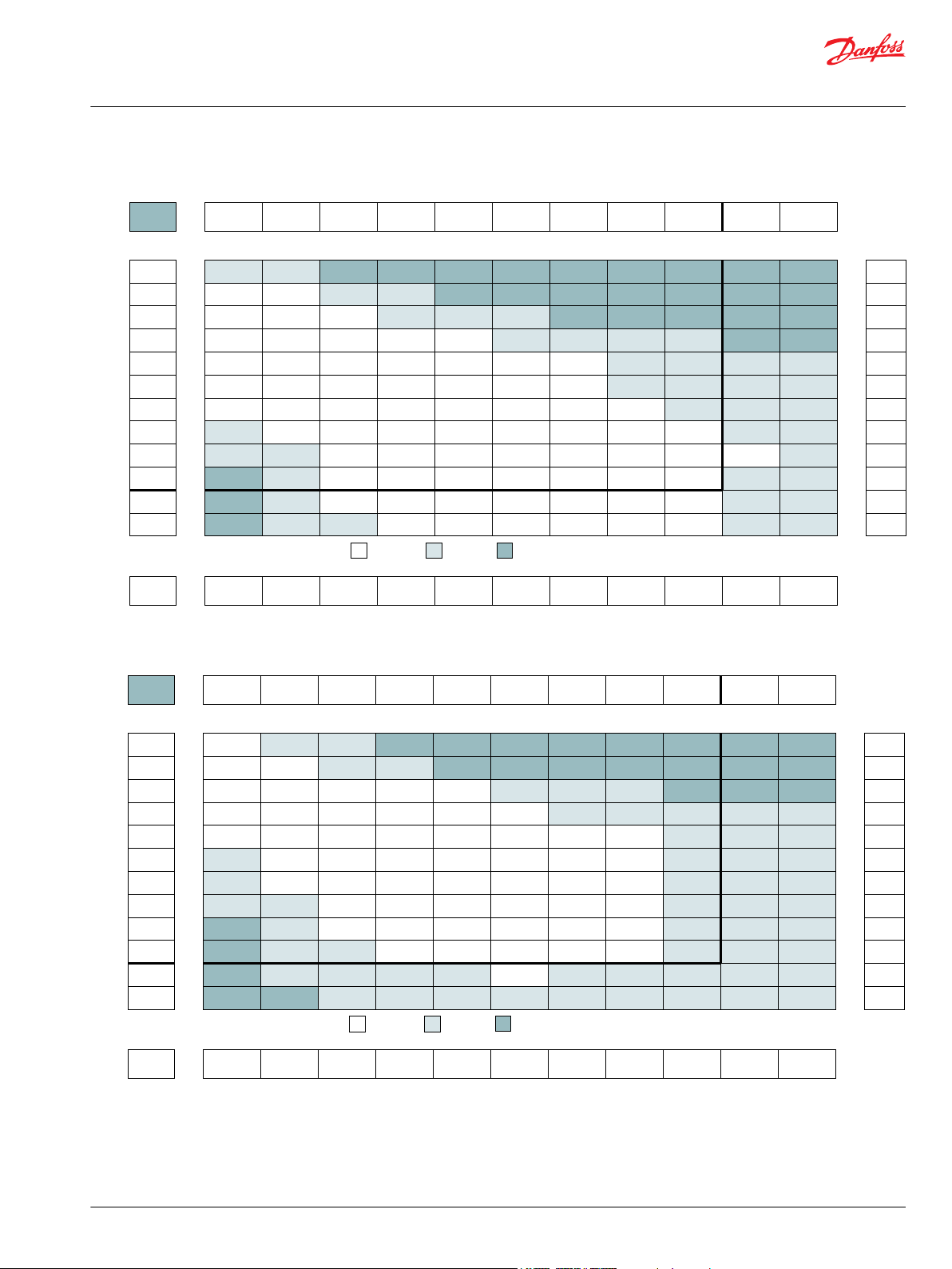
12
24
48
92
140
184
235
278
327
379
11
23
47
89
137
178
230
272
322
374
420
469
5
21
42
84
132
172
222
264
312
360
409
453
20
38
82
128
170
218
259
306
355
400
448
14
34
77
123
164
212
253
300
350
394
442
6
28
73
118
160
208
247
295
342
387
435
22
70
114
152
200
242
289
338
380
428
67
110
147
192
235
281
333
374
421
62
106
142
184
227
276
323
368
412
100
134
178
216
267
316
358
401
94
129
172
210
258
308
346
392
[266]
[283]
[336]
[345]
[354]
[301]
[283]
[212]
[177]
[106]
30
32
38
39
40
34
32
24
20
12
[584]
[620]
[673]
[690]
[699]
[646]
[637]
[620]
[531]
[460]
[407]
[336]
66
70
76
78
79
73
72
70
60
52
46
38
[965]
[1204]
[1389]
[1469]
[1416]
[1451]
[1381]
[1336]
[1274]
[1186]
[1151]
[1062]
109
136
157
166
160
164
156
151
144
134
130
120
[1451]
[1602]
[1814]
[1797]
[1770]
[1735]
[1699]
[1646]
[1575]
[1513]
[1434]
164
181
205
203
200
196
192
186
178
171
162
[1611]
[1788]
[2142]
[2177]
[2168]
[2124]
[2089]
[2053]
[1929]
[1903]
[1760]
182
202
242
246
245
240
236
232
218
215
199
[2213]
[2345]
[2434]
[2567]
[2549]
[2496]
[2460]
[2354]
[2248]
[2195]
[2124]
250
265
275
290
288
282
278
266
254
248
240
[2567]
[2805]
[2832]
[2797]
[2761]
[2744]
[2708]
[2628]
[2575]
[2460]
290
317
320
316
312
310
306
297
291
278
[3169]
[3133]
[3098]
[3071]
[3044]
[2991]
[2956]
[2885]
[2867]
358
354
350
347
344
338
334
326
324
[3540]
[3505]
[3434]
[3443]
[3381]
[3310]
[3283]
[3195]
[3159]
400
396
388
389
382
374
371
361
357
[3575]
[3788]
[3735]
[3708]
[3717]
[3549]
[3478]
[3452]
404
428
422
419
420
401
393
390
[3894]
[3965]
[4018]
[3983]
[3965]
[3912]
[3788]
[3761]
440
448
454
450
448
442
428
425
Torque - Nm [lb-in], Speed rpm
Flow - lpm [gpm]
17 [250] 35 [500] 69 [1000] 86 [1250] 104 [1500] 121 [1750] 138 [2000] 155 [2250] 172 [2500] 190 [2750] 207 [3000]
43 [383] 89 [789] 395 [3495]176 [1556] 219 [1939] 265 [2345] 308 [2728] 352 [3111] 441 [3901] 484 [4284] 527 [4667]
Theoretical Torque - Nm [lb-in]
Max.
Inter.
Max.
Cont.
160
2 [0.5]
4 [1]
8 [2]
15 [4]
23 [6]
30 [8]
38 [10]
45 [12]
53 [14]
61 [16]
68 [18]
76 [20]
13
25
50
94
144
188
238
281
331
381
425
475
Theoretical rpm
Overall Efficiency -
70 - 100%
40 - 69%
0 - 39%
Intermittent Ratings - 10% of Operation
Displacement tested at 54°C [129°F] with an oil viscosity of 46cSt [213 SUS]
Max. Inter.Max. Cont.Pressure - bar [psi]
160 cm3 [9.8 in3] / rev
mm [in]
Rotor
Width
31.8
[1.252]
P109376
10
20
39
75
113
150
192
227
268
8
19
38
73
111
147
190
226
266
308
343
384
6
14
36
70
109
142
185
221
260
300
332
374
5
12
35
68
106
140
182
219
256
298
330
367
9
34
65
103
135
177
212
251
291
322
363
6
28
63
99
131
172
207
245
286
316
355
3
25
59
96
126
167
201
240
279
310
349
22
57
94
124
160
194
233
271
302
343
17
52
89
117
154
186
227
264
296
333
50
84
112
146
179
217
255
286
324
40
78
106
140
174
210
248
276
314
[336]
[416]
[407]
[389]
[354]
[292]
[204]
[186]
[88]
38
47
46
44
40
33
23
21
10
[770]
[912]
[850]
[841]
[814]
[770]
[708]
[646]
[566]
[487]
[407]
[265]
87
103
96
95
92
87
80
73
64
55
46
30
[1522]
[1451]
[1699]
[1717]
[1699]
[1655]
[1593]
[1531]
[1460]
[1372]
[1265]
[1150]
172
164
192
194
192
187
180
173
165
155
143
130
[1779]
[1779]
[2133]
[2133]
[2124]
[2088]
[2035]
[1973]
[1894]
[1805]
[1690]
[1584]
201
201
241
241
240
236
230
223
214
204
191
179
[2159]
[2531]
[2531]
[2549]
[2513]
[2460]
[2398]
[2319]
[2239]
[2124]
[2009]
244
286
286
288
284
278
271
262
253
240
227
[2611]
[2920]
[2947]
[2947]
[2920]
[2876]
[2814]
[2735]
[2655]
[2540]
[2434]
295
330
333
333
330
325
318
309
300
287
275
[2903]
[3292]
[3319]
[3319]
[3327]
[3283]
[3221]
[3150]
[3062]
[2938]
[2841]
328
372
376
375
374
371
364
356
346
332
321
[3690]
[3708]
[3726]
[3726]
[3673]
[3619]
[3540]
[3460]
[3336]
[3230]
417
419
421
421
415
409
400
391
377
365
[3788]
[4080]
[4080]
[4088]
[4062]
[4009]
[3929]
[3841]
[3717]
[3619]
428
461
461
462
459
453
444
434
420
409
[4407]
[4469]
[4460]
[4407]
[4345]
[4274]
[4177]
[4044]
[3805]
498
505
504
498
491
483
472
457
430
[4814]
[4814]
[4796]
[4779]
[4717]
[4646]
[4549]
[4283]
[4142]
544
544
542
540
533
525
514
484
468
Torque - Nm [lb-in], Speed rpm
Flow - lpm [gpm]
17 [250] 35 [500] 69 [1000] 86 [1250] 104 [1500] 121 [1750] 138 [2000] 155 [2250] 172 [2500] 190 [2750] 207 [3000]
54 [481] 109 [963] 489 [4332]218 [1929] 272 [2407] 326 [2888] 381 [3369] 435 [3850] 544 [4813] 598 [5294] 653 [5776]
Theoretical Torque - Nm [lb-in]
Max.
Inter.
Max.
Cont.
200
2 [0.5]
4 [1]
8 [2]
15 [4]
23 [6]
30 [8]
38 [10]
45 [12]
53 [14]
61 [16]
68 [18]
76 [20]
10
20
40
76
116
152
192
227
268
308
343
384
Theoretical rpm
Overall Efficiency -
70 - 100%
40 - 69%
0 - 39%
Intermittent Ratings - 10% of Operation
Displacement tested at 54°C [129°F] with an oil viscosity of 46cSt [213 SUS]
Max. Inter.Max. Cont.Pressure - bar [psi]
198 cm3 [12.1 in3] / rev
mm [in]
Rotor
Width
39.4
[1.553]
P109377
Technical Information
Orbital Motors Type WD, WP and WR
WR Product Line
©
Danfoss | December 2019 BC267362166283en-000201 | 71
Page 72

7
14
29
60
93
125
158
189
6
13
28
59
91
123
155
186
218
249
279
315
3
11
26
56
88
119
150
182
214
245
273
307
3
9
24
53
85
116
147
178
210
242
270
303
7
21
50
81
111
142
174
205
236
267
295
4
19
47
77
106
137
168
201
230
260
290
4
16
44
71
100
131
160
191
222
251
282
11
40
66
93
123
153
183
215
241
272
8
36
60
87
115
145
174
205
231
261
8
33
55
79
106
134
164
195
221
250
28
52
73
99
125
154
184
208
238
[416]
[443]
[469]
[460]
[416]
[372]
[310]
[204]
47
50
53
52
47
42
35
23
[867]
[929]
[982]
[1000]
[956]
[903]
[832]
[752]
[655]
[593]
[487]
[354]
98
105
111
114
109
104
95
85
75
68
56
40
[1743]
[1859]
[1982]
[2062]
[2009]
[1956]
[1885]
[1797]
[1699]
[1593]
[1460]
[1345]
197
210
224
236
227
221
213
203
192
180
165
154
[2186]
[2301]
[2451]
[2575]
[2522]
[2469]
[2398]
[2319]
[2213]
[2106]
[1956]
[1841]
247
260
277
290
285
280
272
262
250
238
221
210
[2717]
[2894]
[3062]
[3027]
[2974]
[2903]
[2823]
[2726]
[2611]
[2469]
[2336]
310
329
346
342
336
328
319
308
295
281
264
[3133]
[3336]
[3531]
[3513]
[3460]
[3398]
[3319]
[3310]
[3106]
[2965]
[2832]
354
377
399
397
391
384
375
365
350
335
320
[3575]
[3752]
[3974]
[3974]
[3938]
[3867]
[3788]
[3699]
[3584]
[3434]
[3310]
404
424
449
449
445
437
428
418
405
388
376
[4151]
[4390]
[4425]
[4398]
[4328]
[4248]
[4160]
[4053]
[3894]
[3770]
469
496
500
497
489
480
470
458
440
428
[4522]
[4788]
[4850]
[4841]
[4788]
[4699]
[4602]
[4496]
[4337]
[4221]
511
541
548
547
541
531
520
510
490
480
[5151]
[5292]
[5266]
[5248]
[5195]
[5089]
[4991]
[4876]
[4797]
[4691]
582
598
595
592
587
575
564
551
545
530
[5646]
[5682]
[5664]
[5620]
[5514]
[5407]
[5310]
[5222]
[5133]
638
642
640
635
623
611
600
590
580
Torque - Nm [lb-in], Speed rpm
Flow - lpm [gpm]
17 [250] 35 [500] 69 [1000] 86 [1250] 104 [1500] 121 [1750] 138 [2000] 155 [2250] 172 [2500] 190 [2750] 207 [3000]
66 [584] 132 [1168] 595 [5265]265 [2345] 331 [2929] 397 [3513] 463 [4097] 529 [4681] 661 [5850] 728 [6442] 794 [7027]
Theoretical Torque - Nm [lb-in]
Max.
Inter.
Max.
Cont.
240
2 [0.5]
4 [1]
8 [2]
15 [4]
23 [6]
30 [8]
38 [10]
45 [12]
53 [14]
61 [16]
68 [18]
76 [20]
8
16
32
63
95
126
158
189
220
252
283
315
Theoretical rpm
Overall Efficiency -
70 - 100%
40 - 69%
0 - 39%
Intermittent Ratings - 10% of Operation
Displacement tested at 54°C [129°F] with an oil viscosity of 46cSt [213 SUS]
Max. Inter.Max. Cont.Pressure - bar [psi]
236 cm3 [14.4 in3] / rev
mm [in]
Rotor
Width
47.4
[1.865]
P109378
31
59
91
119
151
179
211
31
60
90
118
150
179
210
250
271
300
56
88
116
148
178
205
241
268
296
53
85
113
144
177
201
234
263
290
48
81
107
139
174
193
231
255
281
74
103
134
168
188
223
244
273
69
99
132
163
180
214
232
263
64
92
129
158
171
211
221
252
61
87
124
156
162
201
210
242
84
119
148
158
193
200
230
82
116
148
150
185
192
220
[434]
[434]
[398]
[363]
[292]
[195]
[124]
49
49
45
41
33
22
14
[991]
[1018]
[991]
[947]
[858]
[717]
[664]
[549]
[442]
[336]
112
115
112
107
97
81
75
62
50
38
[2097]
[2062]
[2080]
[1938]
[1752]
[1735]
[1575]
[1416]
[1257]
237
233
235
219
198
196
178
160
142
[2611]
[2664]
[2522]
[2416]
[2248]
[2204]
[2080]
[1973]
[1858]
295
301
285
273
254
249
235
223
210
[3150]
[3186]
[3115]
[2920]
[2761]
[2717]
[2584]
[2442]
[2301]
356
360
352
330
312
307
292
276
260
[3699]
[3531]
[3451]
[3257]
[3159]
[3071]
[2965]
[2867]
418
399
390
368
357
347
335
324
[4168]
[3903]
[3841]
[3628]
[3664]
[3540]
[3416]
[3292]
471
441
434
410
414
400
386
372
[4611]
[4522]
[4283]
[4195]
[4133]
[4020]
[3912]
[3805]
521
511
484
474
467
454
442
430
[4965]
[4947]
[4681]
[4425]
[4531]
[4434]
[4336]
[4230]
561
559
529
500
512
501
490
478
[5292]
[5115]
[5204]
[4965]
[4805]
[4690]
[4549]
598
578
588
561
543
530
514
[5522]
[5469]
[5354]
[5398]
[5327]
[5221]
[2133]
624
618
605
610
602
590
580
Torque - Nm [lb-in], Speed rpm
Flow - lpm [gpm]
17 [250] 35 [500]
69 [608] 137 [1215] 275 [2431] 343 [3039] 412 [3646] 481 [4254] 549 [4862] 618 [5469] 687 [6077] 755 [6685] 824 [7292]
Theoretical Torque - Nm [lb-in]
Max.
Inter.
Max.
Cont.
250
8 [2]
15 [4]
23 [6]
30 [8]
38 [10]
45 [12]
53 [14]
61 [16]
68 [18]
76 [20]
32
60
92
120
152
180
212
244
272
304
Theoretical rpm
Overall Efficiency -
70 - 100%
40 - 69%
0 - 39%
Intermittent Ratings - 10% of Operation
Displacement tested at 54°C [129°F] with an oil viscosity of 46cSt [213 SUS]
Max. Inter.Max. Cont.Pressure - bar [psi]
250 cm3 [15.3 in3] / rev
mm [in]
Rotor
Width
49.2
[1.938]
69 [1000] 86 [1250] 104 [1500] 121 [1750] 138 [2000] 155 [2250] 172 [2500] 190 [2750] 207 [3000]
P109379
Technical Information
Orbital Motors Type WD, WP and WR
WR Product Line
72 | © Danfoss | December 2019 BC267362166283en-000201
Page 73

7
13
26
50
76
100
129
153
182
210
6
12
24
49
74
96
126
150
174
202
230
256
5
10
22
46
71
90
122
146
166
193
226
246
4
8
20
44
68
85
118
142
158
184
218
237
3
6
18
40
64
80
116
138
150
175
210
226
4
15
36
61
76
112
133
142
166
202
216
12
32
57
72
106
127
134
160
192
206
8
24
55
70
100
120
128
152
182
198
4
16
52
68
92
106
122
145
174
190
9
48
65
82
100
118
140
164
185
3
40
62
74
95
114
136
158
180
[531]
[549]
[531]
[513]
[496]
[442]
[398]
[336]
[221]
[106]
60
62
60
58
56
50
45
38
25
12
[1018]
[1080]
[1133]
[1177]
[1097]
[1062]
[1009]
[920]
[823]
[726]
[581]
[487]
115
122
128
133
124
120
114
104
93
82
66
55
[1637]
[1655]
[1682]
[1726]
[1770]
[1743]
[1682]
[1593]
[1505]
[1372]
[1239]
[1133]
185
187
190
195
200
197
190
180
170
155
140
128
[2301]
[2345]
[2407]
[2390]
[2372]
[2336]
[2283]
[2230]
[2089]
[1991]
[1929]
[1752]
260
265
272
270
268
264
258
252
236
225
218
198
[2584]
[2690]
[2876]
[2903]
[2929]
[2885]
[2832]
[2779]
[2708]
[2602]
[2478]
[2390]
292
304
325
328
331
326
320
314
306
294
280
270
[2330]
[3292]
[3328]
[3505]
[3487]
[3469]
[3452]
[3381]
[3319]
[3230]
[3098]
365
372
376
396
394
392
390
382
375
365
350
[4036]
[4053]
[4089]
[4115]
[4071]
[4053]
[4000]
[3938]
[3850]
[3770]
456
458
462
465
460
458
452
445
435
426
[4531]
[4620]
[4646]
[4655]
[4611]
[4522]
[4425]
[4319]
[4239]
[4142]
512
522
525
526
521
511
500
488
479
468
[5045]
[5080]
[5009]
[5027]
[4947]
[4868]
[4797]
[4735]
[4655]
[4549]
570
574
566
568
559
550
542
535
526
514
[5576]
[5531]
[5487]
[5443]
[5399]
[5363]
[5266]
[5204]
[5080]
630
625
620
615
610
606
595
588
574
[5876]
[5841]
[5797]
[5708]
[5629]
[5531]
[5443]
[5345]
[5204]
664
660
655
645
636
625
615
604
588
Torque - Nm [lb-in], Speed rpm
Flow - lpm [gpm]
17 [250] 35 [500] 69 [1000]52 [750] 86 [1250] 104 [1500] 121 [1750] 138 [2000] 155 [2250] 172 [2500] 190 [2750]
80 [707] 160 [1415] 639 [5659]240 [2122] 320 [2829] 400 [3537] 480 [4244] 560 [4952] 719 [6366] 799 [7074] 879 [7781]
Theoretical Torque - Nm [lb-in]
Max.
Inter.
Max.
Cont.
290
2 [0.5]
4 [1]
8 [2]
15 [4]
23 [6]
30 [8]
38 [10]
45 [12]
53 [14]
61 [16]
68 [18]
76 [20]
7
14
27
52
79
103
130
155
182
210
234
261
Theoretical rpm
Overall Efficiency -
70 - 100%
40 - 69%
0 - 39%
Intermittent Ratings - 10% of Operation
Displacement tested at 54°C [129°F] with an oil viscosity of 46cSt [213 SUS]
Max. Inter.Max. Cont.Pressure - bar [psi]
291 cm3 [17.8 in3] / rev
mm [in]
Rotor
Width
57.2
[2.252]
P109380
6
12
24
46
70
93
118
140
165
188
5
11
22
45
69
92
117
138
163
186
210
235
5
10
20
44
68
89
115
136
161
184
208
233
4
9
19
43
66
86
113
134
158
182
204
230
6
17
41
63
82
110
130
154
177
197
226
4
16
38
58
77
104
124
147
170
190
218
2
13
35
53
73
98
117
141
162
181
209
11
32
49
67
91
110
134
155
173
202
6
28
47
63
85
103
126
147
165
193
2
24
43
59
77
97
118
138
156
185
[531]
[619]
[646]
[699]
[602]
[496]
[478]
[336]
[195]
[97]
60
70
73
79
68
56
54
38
22
11
[1186]
[1239]
[1363]
[1345]
[1328]
[1283]
[1239]
[1186]
[1080]
[930]
[779]
[620]
134
140
154
152
150
145
140
134
122
105
88
70
[1673]
[2115]
[2062]
[2080]
[2009]
[1929]
[1788]
[1681]
[1531]
[1389]
[1274]
[1062]
189
239
233
235
227
218
202
192
173
157
144
126
[2106]
[2442]
[2575]
[2752]
[2611]
[2531]
[2416]
[2301]
[2257]
[2027]
[1947]
[1681]
238
276
291
311
295
286
273
260
255
229
220
190
[2867]
[2947]
[3407]
[3345]
[3150]
[3080]
[2973]
[2858]
[2637]
[2522]
[2319]
324
333
385
378
356
348
336
323
298
285
262
[3478]
[3761]
[4000]
[3920]
[3858]
[3779]
[3619]
[3460]
[3327]
[3150]
[2965]
393
425
452
443
436
427
409
391
376
356
335
[3566]
[4310]
[4584]
[4531]
[4478]
[4434]
[4212]
[3991]
[3894]
[3752]
[3628]
403
487
518
512
506
501
476
451
440
424
410
[4823]
[4912]
[5115]
[4956]
[4929]
[4796]
[4611]
[4451]
[4310]
[4097]
545
555
578
560
557
542
521
503
487
463
[5496]
[5673]
[5496]
[5434]
[5345]
[5319]
[5150]
[4929]
[4858]
[4673]
621
641
621
614
604
601
582
557
549
528
[5832]
[6106]
[6071]
[5885]
[5876]
[5681]
[5575]
[5469]
[5327]
[5186]
659
690
686
665
664
642
630
618
602
586
Torque - Nm [lb-in], Speed rpm
Flow - lpm [gpm]
17 [250] 35 [500] 52 [750] 69 [1000] 86 [1250] 104 [1500] 121 [1750] 138 [2000] 155 [2250] 172 [2500]
87 [770] 177 [1566] 708 [6265]267 [2362] 354 [3132] 441 [3903] 533 [4717] 620 [5487] 795 [7035] 887 [7850]
Theoretical Torque - Nm [lb-in]
Max.
Inter.
Max.
Cont.
320
2 [0.5]
4 [1]
8 [2]
15 [4]
23 [6]
30 [8]
38 [10]
45 [12]
53 [14]
61 [16]
68 [18]
76 [20]
6
12
25
47
71
93
118
140
165
189
211
236
Theoretical rpm
Overall Efficiency -
70 - 100%
40 - 69%
0 - 39%
Intermittent Ratings - 10% of Operation
Displacement tested at 54°C [129°F] with an oil viscosity of 46cSt [213 SUS]
Max. Inter.Max. Cont.Pressure - bar [psi]
322 cm3 [19.6 in3] / rev
mm [in]
Rotor
Width
63.5
[2.502]
P109381
Technical Information
Orbital Motors Type WD, WP and WR
WR Product Line
©
Danfoss | December 2019 BC267362166283en-000201 | 73
Page 74
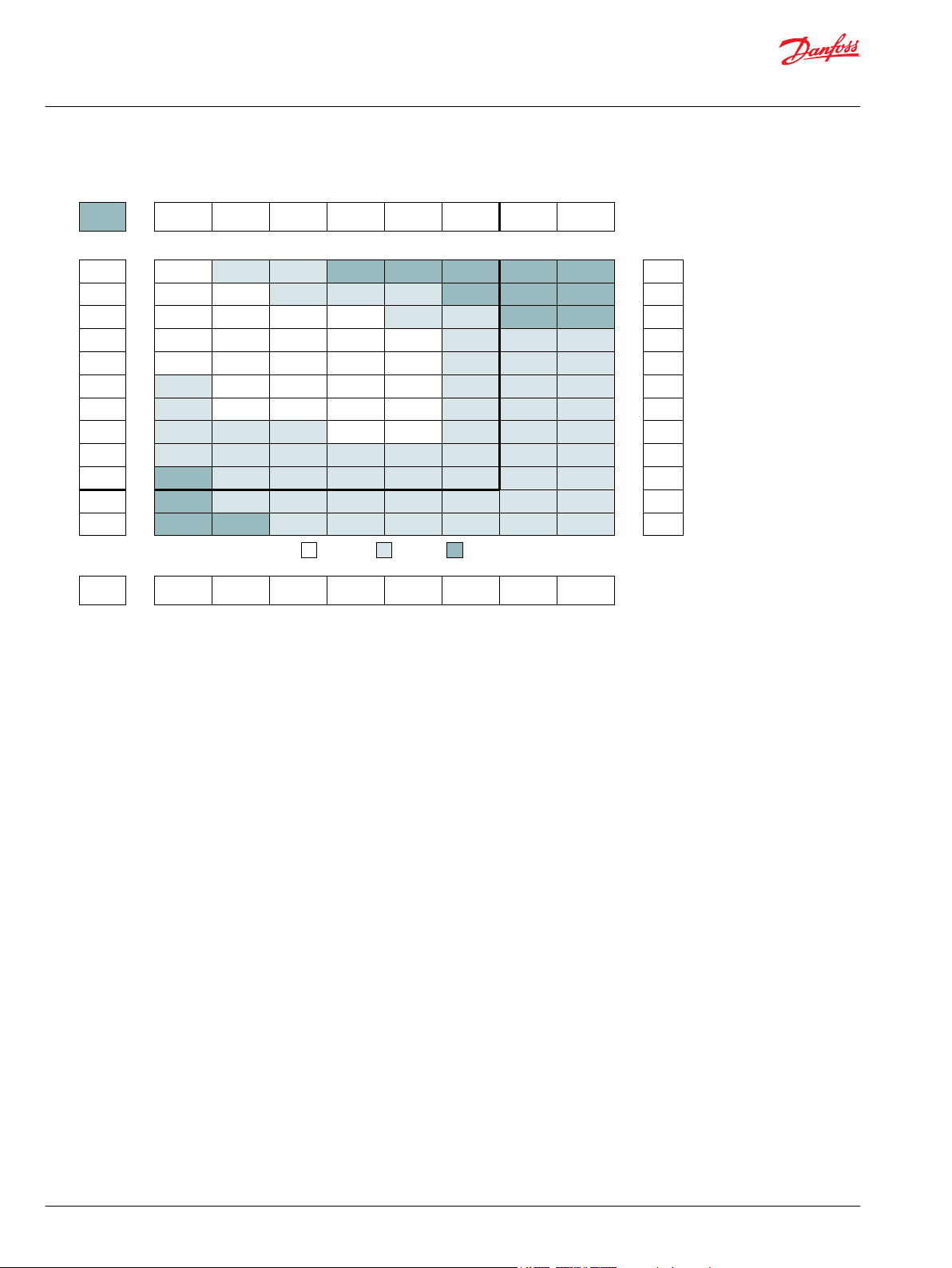
5
10
20
38
58
75
95
113
133
4
9
19
37
56
73
93
111
131
152
170
190
3
8
18
36
55
71
92
108
127
147
164
185
2
7
17
34
53
69
87
105
126
145
163
180
2
6
15
33
50
66
84
103
121
139
156
174
4
13
32
49
63
81
96
114
130
146
165
3
11
28
46
60
78
91
109
127
142
160
2
8
25
44
58
75
88
104
121
137
156
[723]
[761]
[791]
[771]
[703]
[620]
[523]
[460]
[404]
82
86
89
87
79
70
59
52
46
[1459]
[1549]
[1690]
[1673]
[1637]
[1558]
[1407]
[1283]
[1221]
[1000]
[850]
[655]
165
175
191
189
185
176
159
145
138
113
96
74
[2213]
[2317]
[2513]
[2451]
[2398]
[2301]
[2115]
[2062]
[1903]
[1690]
[1575]
[1327]
250
262
284
277
271
260
239
233
215
191
178
150
[2912]
[3053]
[3219]
[3346]
[3305]
[3217]
[3106]
[2968]
[2813]
[2641]
[2328]
[2122]
329
345
364
378
373
364
351
335
318
298
263
240
[3699]
[3779]
[3962]
[4135]
[4110]
[4025]
[3913]
[3806]
[3622]
[3448]
[3230]
[3027]
418
427
448
467
464
455
442
430
409
390
365
342
[4398]
[4443]
[4679]
[4873]
[4868]
[4787]
[4684]
[4543]
[4393]
[4228]
[3855]
497
502
529
551
550
541
529
513
496
478
436
[5106]
[5363]
[5569]
[5584]
[5515]
[5410]
[5269]
[5115]
[4959]
[4572]
[4365]
577
606
629
631
623
611
595
578
560
517
493
[5841]
[6036]
[6177]
[6159]
[5982]
[5864]
[5705]
[5522]
[5364]
[5133]
[4956]
660
682
698
696
676
663
645
624
606
580
560
Torque - Nm [lb-in], Speed rpm
Flow - lpm [gpm]
17 [250] 35 [500] 52 [750] 69 [1000] 86 [1250] 104 [1500] 121 [1750] 138 [2000]
Pressure - bar [psi]
112 [992] 224 [1984] 897 [7935]336 [2976] 448 [3968] 560 [4960] 673 [5952] 785 [6944]
Theoretical Torque - Nm [lb-in]
Max.
Inter.
Max.
Cont.
400
2 [0.5]
4 [1]
8 [2]
15 [4]
23 [6]
30 [8]
38 [10]
45 [12]
53 [14]
61 [16]
68 [18]
76 [20]
5
10
20
38
58
75
95
113
133
153
170
190
Theoretical rpm
Overall Efficiency -
70 - 100%
40 - 69%
0 - 39%
Intermittent Ratings - 10% of Operation
Displacement tested at 54°C [129°F] with an oil viscosity of 46cSt [213 SUS]
Max. Inter.Max. Cont.
400 cm3 [24.4 in3] / rev
mm [in]
Rotor
Width
78.9
[3.106]
P109382
Technical Information
Orbital Motors Type WD, WP and WR
WR Product Line
74 | © Danfoss | December 2019 BC267362166283en-000201
Page 75
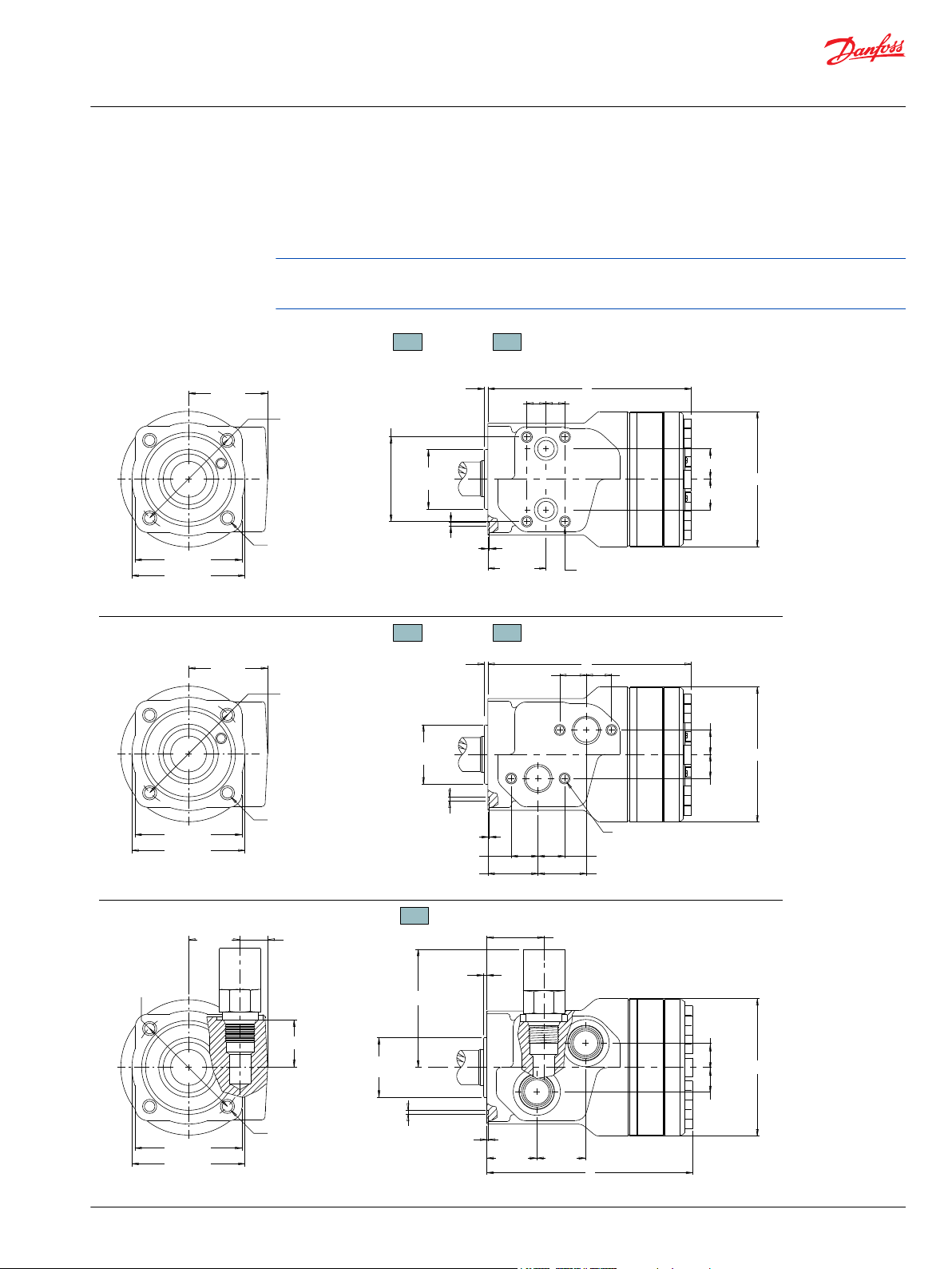
80.0 [3.150]
83.8 [3.299]
Ø82.6 [3.250]
19 [.77]
80.0 [3.150]
83.8 [3.299]
Ø82.6 [3.250]
55 [2.17]
F37 - (4) 3/8-16 UNC, Min. Depth 16 [.63]
G37 - (4) M10 x 1.5, Min. Depth 16 [.63]
80.0 [3.150]
83.8 [3.299]
Ø82.6 [3.250]
55 [2.17]
(4) 3/8-16 UNC
Min. Depth 16 [.63]
F37 - (4) 5/16-18 UNC, Min. Depth 12 [.47]
G37 - (4) M8 x 1.25, Min. Depth 12 [.47]
(4) 3/8-16 UNC, Min. Depth 16 [.63]
F33 - (4) M8 x 1.25, Min. Depth 12 [.47]
F3D - (4) 5/16-18 UNC, Min. Depth 12 [.47]
Ø101.6 [4.00]
18 [.71]
18 [.71]
Ø44.45 [1.750]
Ø44.35 [1.746]
2.7 [.106]
2.3 [.091]
14 [.56] 14 [.56]
63.5 [2.50]
44 [1.72]
L
B
A
20 [.79]
38 [1.48]
20 [.79]
36 [1.42]
20 [.79] 20 [.79]
L
B
A
Ø44.45 [1.750]
Ø44.35 [1.746]
2.7 [.106]
2.3 [.091]
A
B
40 [1.57]
32 [1.28]
Ø101.6 [4.00]
23 [.90]
23 [.90]
Ø44.45 [1.750]
Ø44.35 [1.746]
2.7 [.106]
2.3 [.091]
44 [1.72]
87 [3.42]
38 [1.48] 36 [1.42]
L
Ø101.6 [4.00]
18 [.71]
18 [.71]
3.0 [.118]
1.2 [.047]
3.0 [.118]
1.2 [.047]
1.2 [.047]
3.0 [.118]
4-HOLE, SQUARE MOUNT, OFFSET MANIFOLD PORTS
F39
7/8-14 UNF
4-HOLE, SQUARE MOUNT, OFFSET PORTS, VALVE CAVITY
F33
G 1/2
F3D
7/8-14 UNF
4-HOLE, SQUARE MOUNT, ALIGNED MANIFOLD PORTS
F37 1/2” Drilled G37 1/2” Drilled
P109383
Technical Information
Orbital Motors Type WD, WP and WR
WR Product Line
WR 251 and 252 Series
WR 251 and 252 Series Housings
Dimensions shown are without paint. Paint thickness can be up to 0.13 [.005].
Dimensions are charted in WR 251 and 252 Series Technical Information on page 76.
©
Danfoss | December 2019 BC267362166283en-000201 | 75
Page 76

82 [3.220] Max.
82 [3.220] Max.
Ø82.6 [3.250]
82 [3.220] Max.
88 [3.449] Max.
Ø44.45 [1.750]
Ø44.35 [1.746]
A
23 [.91]
23 [.91]
Ø101.6 [4.000]
N
23 [.90]
23 [.90]
Ø101.6 [4.000]
N
(4) 3/8-16 UNC, Min. Depth 13 [.51]
Ø82.6 [3.250]
82 [3.220] Max.
88 [3.449] Max.
(4) 3/8-16 UNC, Min. Depth 13 [.51]
43 [1.68]2.8 [.110]
B
(4) 5/16-18 UNC, Min. Depth 12 [.47]
14 [.56]
14 [.56]
64 [2.50]
43 [1.68]2.8 [.110]
Ø44.45 [1.750]
Ø44.35 [1.746]
A
B
3.0 [.118]
1.2 [.047]
3.0 [.118]
1.2 [.047]
4-HOLE, SQUARE MOUNT, ALIGNED MANIFOLD PORTS
F37
1/2” Drilled
4-HOLE, SQUARE MOUNT, ALIGNED PORTS
F30 1/2-14 NPT F31 7/8-14 UNF
P109385
Technical Information
Orbital Motors Type WD, WP and WR
WR Product Line
WR 251 and 252 Series Technical Information
Allowable Shaft Load / Bearing Curve
The bearing curve below represents the side load capacity of the motor at the centerline of the key for
various motor speeds. Operating conditions within the shaded area will maintain acceptable oil film
lubrication with recommended fluids. Operating conditions outside the shaded area are susceptible to
motor failure due to oil starvation and/or excessive heat generation. Fluids with low lubricity or low
viscosity may require the maximum load and speed ratings to be derated to provide acceptable motor
life and performance.
76 | © Danfoss | December 2019 BC267362166283en-000201
Page 77
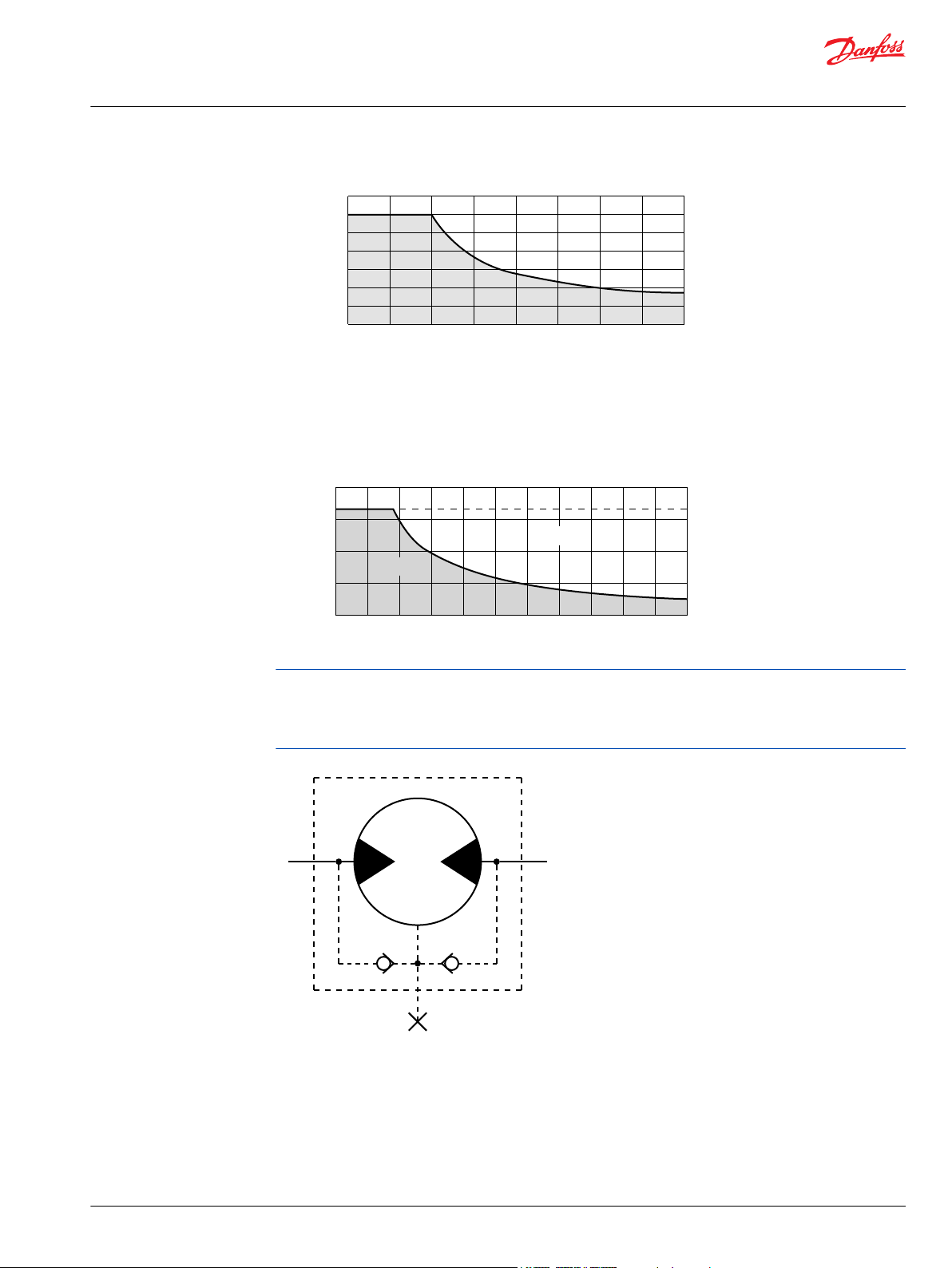
6000 [1350]
N [lbf]
4000 [900]
2000 [450]
0 600 rpm700500400300200100
P109389
276 [4000]
207 [3000]
69 [1000]
138 [2000]
bar [psi]
0 1000900 rpm600 800700500400300200100
Continuous
Intermittent
P109390
P109354
Technical Information
Orbital Motors Type WD, WP and WR
WR Product Line
Permissible Shaft Seal Pressure
The curve below represents allowable seal pressure at various speeds. Operation in the gray area results
in maintaining the rated life of the shaft seal. Actual shaft seal pressure depends on motor configuration.
With check valves and drain connection, the shaft seal pressure equals pressure in the drain line. With
check valves and no drain connection, shaft seal pressure is identical to output pressure. No check valves
and no drain connection, the shaft seal pressure is identical to the average value of input and output
pressure.
©
Danfoss | December 2019 BC267362166283en-000201 | 77
Page 78
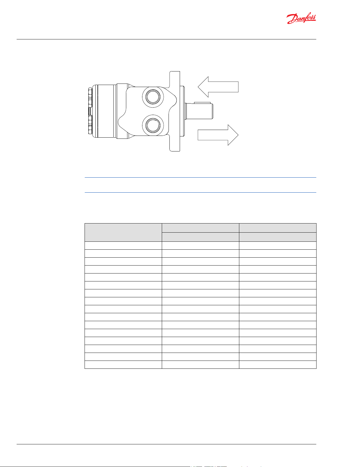
222 daN [500 lb]
445 daN [1000 lb]
P109391
Technical Information
Orbital Motors Type WD, WP and WR
WR Product Line
Length and Weight Chart
251 and 252 series motor weights can vary ± 0.5 kg [1 lb] depending on model configurations such as
housing, shaft, endcover, options etc.
Dimension N is the overall motor length from the rear of the motor to the mounting flange surface and is
referenced on detailed housing drawings listed in WR 251 and 252 Series Housings on page 75.
Dimension N
# Length Weight
mm [in] kg [lb]
040 127 [4.98] 6.3 [14.0]
050 128 [5.06] 6.4 [14.2]
060 130 [5.13] 6.5 [14.3]
070 132 [5.21] 6.6 [14.5]
080 134 [5.28] 6.7 [14.8]
090 136 [5.34] 6.8 [14.9]
100 138 [5.44] 6.9 [15.1]
115 141 [5.54] 7.0 [15.3]
130 144 [5.67] 7.1 [15.6]
160 150 [5.92] 7.4 [16.2]
200 158 [6.22] 7.7 [17.0]
240 166 [6.53] 8.0 [17.7]
250 168 [6.60] 8.1 [17.9]
290 176 [6.92] 8.5 [18.7]
320 182 [7.17] 8.7 [19.2]
400 197 [7.77] 9.4 [20.7]
78 | © Danfoss | December 2019 BC267362166283en-000201
Page 79
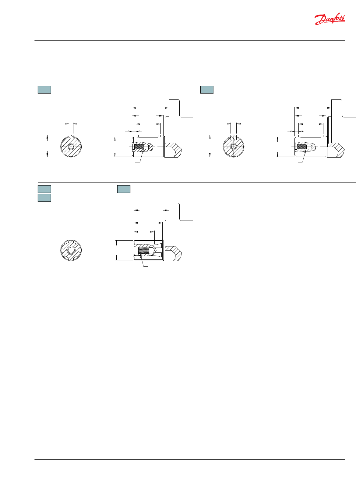
25.40 [1.000]
25.38 [0.999]
25 [1.00]
Min. Depth
02 - 16 [.63]
03 - 20 [.80]
04 - 13 [.51]
1/4-20 UNC,
Min. Depth 16 [.63]
Ø25.40 [1.000]
Ø25.38 [.999]
40 [1.57]
02 - 46 [1.79]
03 - 64 [2.51]
04 - 46 [1.79]
46 [1.79]
40 [1.57]
6B Spline
SAE J499 Standard
6.35 [.250]
6.30 [.248]
28.2 [1.122]
28.0 [1.100]
5 [.20]
32 [1.24]
25.02 [.985]
25.00 [.984]
M8 x 1.25,
Min. Depth 13 [.51]
46 [1.79]
40 [1.57]
7.95 [.313]
7.93 [.312]
28.0 [1.102]
27.7 [1.091]
5 [.20]
32 [1.25]
10 1” Straight
Max. Torque: 655 Nm [5800 lb-in]
02 1” 6B Spline, 1/4-20 Tap
Max. Torque: 678 Nm [6000 lb-in]
04 1” 6B Spline, M8x1.25 Tap
Max. Torque: 678 Nm [6000 lb-in]
12 25mm Straight
03
1” 6B Spline, 5/16-18
P109392
Technical Information
Orbital Motors Type WD, WP and WR
WR Product Line
WR 251 and 252 Series Shafts
©
Danfoss | December 2019 BC267362166283en-000201 | 79
Page 80

1 2 3 4 5 6 7 8
40 cm3/rev [2.5 in3/rev]
50 cm3/rev [3.1 in3/rev]
59 cm3/rev [3.6 in3/rev]
71 cm3/rev [4.3 in3/rev]
79 cm3/rev [4.9 in3/rev]
88 cm3/rev [5.4 in3/rev]
100 cm3/rev [6.1 in3/rev]
113 cm3/rev [6.9 in3/rev]
Standard Rotation Reverse Rotation
The 251 & 252 series are bi-directional.
129 cm3/rev [7.9 in3/rev]
160 cm3/rev [9.8 in3/rev]
198 cm3/rev [12.1 in3/rev]
236 cm3/rev [14.4 in3/rev]
250 cm3/rev [15.3 in3/rev]
291 cm3/rev [17.8 in3/rev]
322 cm3/rev [19.6 in3/rev]
400 cm3/rev [24.4 in3/rev]
2-Hole, SAE A Mount, Aligned Ports, 1/2-14 NPT
2-Hole, SAE A Mount, Aligned Ports, 7/8-14 UNF
2-Hole, SAE A Mount, Aligned Manifold Ports, 1/2” Drilled
2-Hole, SAE A Mount, Offset Manifold Ports, G 1/2
2-Hole, SAE A Mount, Aligned Side Ports, 7/8-14 UNF
4-Hole, Square Mount, Aligned Ports, 1/2-14 NPT
4-Hole, Square Mount, Aligned Ports, 7/8-14 UNF
4-Hole, Square Mount, Aligned Manifold Ports, 1/2” Drilled
6B Spline, 1/4 Tap
6B Spline, 5/16 Tap (Ext)
6B Spline, M8 Tap
1” Straight
25mm Straight
Black
Black, Unpainted Mounting Surface
Standard
Speed Sensor, Dual, 4-Pin Male Weatherpack Connector
Speed Sensor, Dual, 4-Pin M12 Male Connector
Speed Sensor, Single, 3-Pin Male Weatherpack Connector
Speed Sensor, Single, 4-Pin M12 Male Connector
None
Freeturning Rotor
The 03 extended shaft is designed for use with one of the speed sensor options listed in
STEP 7.
None
251
1. CHOOSE SERIES DESIGNATION
2. SELECT A DISPLACEMENT OPTION
040
050
060
070
080
090
100
115
130
160
200
240
250
290
320
400
3. SELECT A MOUNT & PORT OPTION
A10
A11
A17
A18
A71
F30
F31
F37
4. SELECT A SHAFT OPTION
02
03
04
10
12
5. SELECT A PAINT OPTION
A
B
6. SELECT A VALVE CAVITY / CARTRIDGE OPTION
7. SELECT AN ADD-ON OPTION
A
W
X
Y
Z
8. SELECT A MISCELLANEOUS OPTION
AA
AC
252
A
P109396
Technical Information
Orbital Motors Type WD, WP and WR
WR Product Line
WR 251 and 252 Series Ordering Information
80 | © Danfoss | December 2019 BC267362166283en-000201
Page 81

Technical Information
Orbital Motors Type WD, WP and WR
WR Product Line
WR 255 and 256 Series
WR 255 and 256 Series Housings
Dimensions shown are without paint. Paint thickness can be up to 0.13 [.005].
Dimensions are charted in WR 255 and 256 Series Technical Information on page 85.
(TP) - Taller Pilot Height. Refer to detailed drawing for dimensional differences.
©
Danfoss | December 2019 BC267362166283en-000201 | 81
Page 82

130.3 [5.13]
Ø106.4 [4.19]
59.4 [2.34]51 [2.00]
Ø13.7 [.539]
Ø13.5 [.531]
130.3 [5.13]
Ø106.4 [4.19]
55 [2.17]51 [2.00]
Ø13.7 [.539]
Ø13.5 [.531]
130.3 [5.13]
Ø106.4 [4.19]
59.4 [2.34]51 [2.00]
Ø82.50 [3.249]
Ø82.35 [3.242]
36.1 [1.42]
A
B
18 [.71]
18 [.71]
Ø101.6 [4.00]
K
2.7 [.105]
Ø82.50 [3.249]
Ø82.35 [3.242]
43.5 [1.71]
A
B
22.9 [.90]
22.9 [.90]
Ø101.6 [4.00]
K
20 [.79] 20 [.79]
Ø13.7 [.539]
Ø13.5 [.531]
A12 - 37 [1.48]
A62 - 35 [1.38]
A1D - (4) 5/16-18 UNC
A13, A63 - (4) M8 x 1.25
Min. Depth 12 [.475]
A12 - 2.7 [.105]
A62 - 5.2 [.205]
Ø82.50 [3.249]
Ø82.35 [3.242]
36.1 [1.42]
A
B
18 [.71]
18 [.71]
Ø101.6 [4.00]
K
A13, A1D - 37 [1.48]
A63 - 35 [1.38]
A13, A1D - 2.7 [.105]
A63 - 5.2 [.205]
20 [.79]
20 [.79]
3.2 [.126]
1.2 [.047]
3.2 [.126]
1.2 [.047]
3.2 [.126]
1.2 [.047]
2-HOLE, SAE A MOUNT, OFFSET PORTS
A13
G 1/2
2-HOLE, SAE A MOUNT, OFFSET MANIFOLD PORTS
A1D
7/8-14 UNF
A12
G 1/2
A62
G 1/2 (TP)
2-HOLE, SAE A MOUNT, ALIGNED PORTS
A10 1/2-14 NPT A11 7/8-14 UNF
A63
G 1/2 (TP)
P109386
Technical Information
Orbital Motors Type WD, WP and WR
WR Product Line
82 | © Danfoss | December 2019 BC267362166283en-000201
Page 83

43.5 [1.71]
2.7 [.105]
54 [2.14]
A
B
K
37 [1.48]
1.2 [.047]
32 [1.28]
Ø106.4 [4.19]
40 [1.58]51 [2.00]
Ø13.7 [.539]
Ø13.5 [.531]
Spotface Ø 17.5 [.689]
2 [.079] Min. deep
14 [.56]
14 [.56]
59.4 [2.34]
106.4 [4.189]
13.5 [.531]
22.5° 22.5°
130.3 [5.13]
Ø106.4 [4.19]
55 [2.17]51 [2.00]
Ø82.50 [3.249]
Ø82.35 [3.242]
36.1 [1.42]
18 [.71]
18 [.71]
Ø101.6 [4.00]
2.7 [.105]
Ø82.50 [3.249]
Ø82.35 [3.242]
43.5 [1.71]
A
B
22.9 [.90]
22.9 [.90]
Ø101.6 [4.00]
K
Ø13.7 [.539]
Ø13.5 [.531]
(4) 5/16-18 UNC, Min. Depth 12 [.475]
2.7 [.105]
Ø82.50 [3.249]
Ø82.35 [3.242]
43.5 [1.71]
A
B
22.9 [.90]
22.9 [.90]
Ø101.6 [4.00]
K
63.5 [2.50]
1.2 [.047]
3.2 [.126]
3.2 [.126]
3.2 [.126]
1.2 [.047]
2-HOLE, SAE A MOUNT, OFFSET PORTS, VALVE CAVITY
A30 1/2-14 NPT4-HOLE, MAGNETO MOUNT, ALIGNED PORTS A31 7/8-14 UNF
A19
7/8-14 UNF
2-HOLE, SAE A MOUNT, ALIGNED MANIFOLD PORTS
A17 1/2” Drilled
P109387
Technical Information
Orbital Motors Type WD, WP and WR
WR Product Line
©
Danfoss | December 2019 BC267362166283en-000201 | 83
Page 84
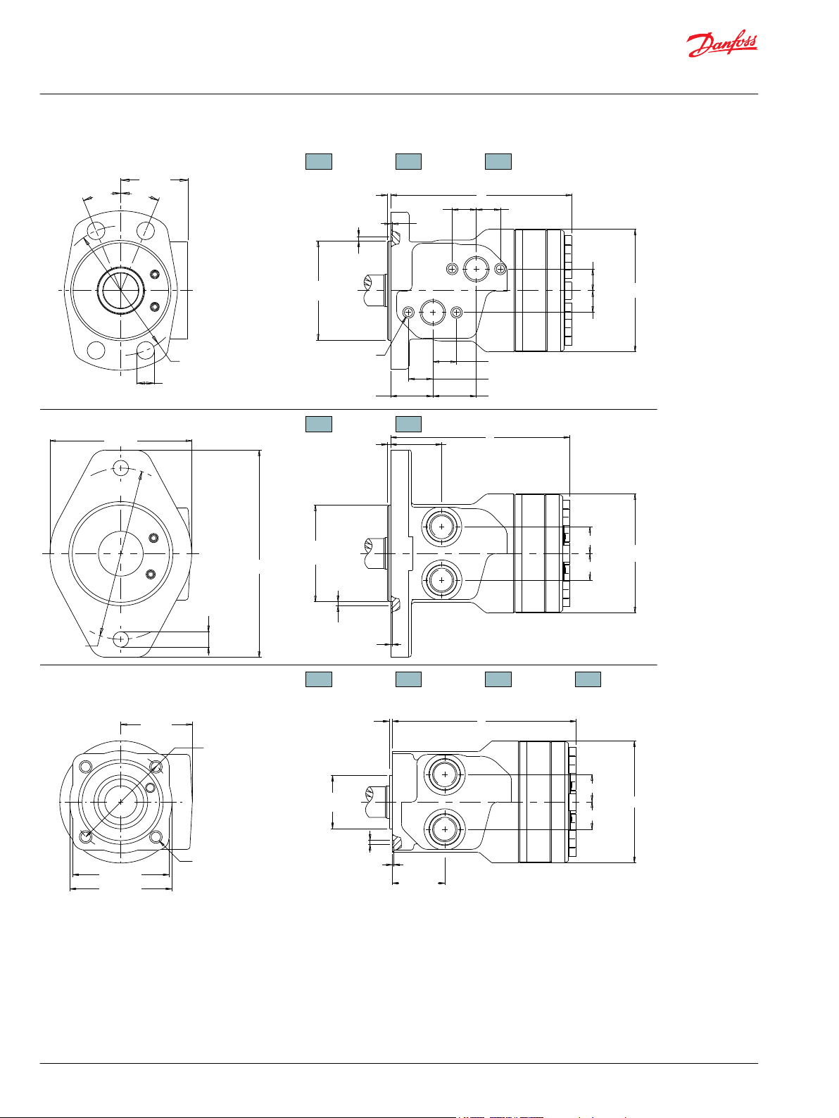
176,8 [6.96]
Ø146.1 [5.75]
Ø13.1 [.516]
43.5 [1.71]
A
B
2.7 [.105]
Ø101.60 [4.000]
Ø101.42 [3.993]
L
80.0 [3.150]
83.8 [3.299]
Ø82.6 [3.250]
43.7 [1.720]
Ø101.6 [4.00]
23 [.90]
23 [.90]
A
B
L
Ø44.45 [1.750]
Ø44.35 [1.746]
2.5 [.098]
121 [4.76]
23 [.90]
23 [.90]
Ø101.6 [4.00]
55 [2.17]
106.4 [4.189]
13.5 [.531]
22.5° 22.5°
20 [.79] 20 [.79]
A33, A3D - (4) 5/16-18 UNC
AC3 - (4) M8 x 1.25
Min. Depth 11.8 [.465]
Ø82.50 [3.249]
Ø82.35 [3.242]
36.1 [1.42]
A
B
18 [.71]
18 [.71]
Ø101.6 [4.00]
K
A33, A3D - 37 [1.48]
AC3 - 35 [1.38]
A33, A3D - 2.7 [.105]
AC3 - 5.2 [.205]
20 [.79]
20 [.79]
59 [2.34]
F30, F31, F38 - (4) 3/8-16 UNC
Min. Depth 16 [.63]
G38 - (4) M10 x 1.5
Min. Depth 16 [.63]
1.2 [.047]
3.2 [.126]
3.2 [.126]
1.2 [.047]
3.0 [.118]
1.2 [.047]
2-HOLE, SAE B MOUNT, ALIGNED PORTS
F30
1/2-14 NPT4-HOLE, SQUARE MOUNT, ALIGNED PORTS
F31
7/8-14 UNF
B11
7/8-14 UNF
B18
G 1/2
4-HOLE, MAGNETO MOUNT, OFFSET MANIFOLD
A33 G 1/2 A3D 7/8-14 UNF
F38 G 1/2
AC3
G 1/2 (TP)
G38 G 1/2
P109388
Technical Information
Orbital Motors Type WD, WP and WR
WR Product Line
84 | © Danfoss | December 2019 BC267362166283en-000201
Page 85

80.0 [3.150]
83.8 [3.299]
Ø82.6 [3.250]
19 [.77]
80.0 [3.150]
83.8 [3.299]
Ø82.6 [3.250]
55 [2.17]
F37 - (4) 3/8-16 UNC, Min. Depth 16 [.63]
G37 - (4) M10 x 1.5, Min. Depth 16 [.63]
80.0 [3.150]
83.8 [3.299]
Ø82.6 [3.250]
55 [2.17]
(4) 3/8-16 UNC
Min. Depth 16 [.63]
F37 - (4) 5/16-18 UNC, Min. Depth 12 [.47]
G37 - (4) M8 x 1.25, Min. Depth 12 [.47]
(4) 3/8-16 UNC, Min. Depth 16 [.63]
F33 - (4) M8 x 1.25, Min. Depth 12 [.47]
F3D - (4) 5/16-18 UNC, Min. Depth 12 [.47]
Ø101.6 [4.00]
18 [.71]
18 [.71]
Ø44.45 [1.750]
Ø44.35 [1.746]
2.7 [.106]
2.3 [.091]
14 [.56] 14 [.56]
63.5 [2.50]
44 [1.72]
L
B
A
20 [.79]
38 [1.48]
20 [.79]
36 [1.42]
20 [.79] 20 [.79]
L
B
A
Ø44.45 [1.750]
Ø44.35 [1.746]
2.7 [.106]
2.3 [.091]
A
B
40 [1.57]
32 [1.28]
Ø101.6 [4.00]
23 [.90]
23 [.90]
Ø44.45 [1.750]
Ø44.35 [1.746]
2.7 [.106]
2.3 [.091]
44 [1.72]
87 [3.42]
38 [1.48] 36 [1.42]
L
Ø101.6 [4.00]
18 [.71]
18 [.71]
3.0 [.118]
1.2 [.047]
3.0 [.118]
1.2 [.047]
1.2 [.047]
3.0 [.118]
4-HOLE, SQUARE MOUNT, OFFSET MANIFOLD PORTS
F39 7/8-14 UNF
4-HOLE, SQUARE MOUNT, OFFSET PORTS, VALVE CAVITY
F33
G 1/2
F3D
7/8-14 UNF
4-HOLE, SQUARE MOUNT, ALIGNED MANIFOLD PORTS
F37 1/2” Drilled G37 1/2” Drilled
P109398
Technical Information
Orbital Motors Type WD, WP and WR
WR Product Line
WR 255 and 256 Series Technical Information
Allowable Shaft Load / Bearing Curve
The bearing curve below represents the side load capacity of the motor at the centerline of the key for
various motor speeds. Operating conditions within the shaded area will maintain acceptable oil film
©
Danfoss | December 2019 BC267362166283en-000201 | 85
Page 86

6000 [1350]
N [lbf]
4000 [900]
2000 [450]
0 600 rpm700500400300200100
P109389
276 [4000]
207 [3000]
69 [1000]
138 [2000]
bar [psi]
0 1000900 rpm600 800700500400300200100
Continuous
Intermittent
P109390
P109354
Technical Information
Orbital Motors Type WD, WP and WR
WR Product Line
lubrication with recommended fluids. Operating conditions outside the shaded area are susceptible to
motor failure due to oil starvation and/or excessive heat generation. Fluids with low lubricity or low
viscosity may require the maximum load and speed ratings to be derated to provide acceptable motor
life and performance.
Permissible Shaft Seal Pressure
The curve below represents allowable seal pressure at various speeds. Operation in the gray area results
in maintaining the rated life of the shaft seal. Actual shaft seal pressure depends on motor configuration.
With check valves and drain connection, the shaft seal pressure equals pressure in the drain line. With
check valves and no drain connection, shaft seal pressure is identical to output pressure. No check valves
and no drain connection, the shaft seal pressure is identical to the average value of input and output
pressure.
86 | © Danfoss | December 2019 BC267362166283en-000201
Page 87

222 daN [500 lb]
445 daN [1000 lb]
P109391
Technical Information
Orbital Motors Type WD, WP and WR
WR Product Line
Thrust Load
Length and Weight Chart
255 and 256 series motor weights can vary ± 0.5 kg [1 lb] depending on model configurations such as
housing, shaft, endcover, options etc.
Dimension K is the overall motor length from the rear of the motor to the mounting flange surface and is
referenced on detailed housing drawings listed in WR 255 and 256 Series Housings on page 81.
Dimension K
# 3 mm Pilot 8 mm Pilot Weight
mm [in] mm [in] kg [lb]
040 142 [5.60] 140 [5.50] 6.6 [14.5]
050 144 [5.67] 142 [5.57] 6.6 [14.5]
060 146 [5.74] 144 [5.64] 6.7 [14.7]
070 147 [5.80] 145 [5.70] 6.7 [14.7]
080 150 [5.91] 148 [5.81] 6.8 [15.0]
090 151 [5.96] 149 [5.86] 6.8 [15.0]
100 154 [6.06] 152 [5.96] 6.9 [15.2]
115 156 [6.15] 154 [6.05] 7.1 [15.6]
130 160 [6.28] 158 [6.18] 7.3 [16.0]
160 166 [6.53] 164 [6.43] 7.5 [16.5]
200 173 [6.83] 171 [6.73] 8.0 [17.6]
240 182 [7.15] 180 [7.05] 8.5 [18.7]
250 183 [7.20] 181 [7.10] 8.5 [18.7]
290 192 [7.56] 190 [7.46] 8.8 [19.4]
320 198 [7.78] 196 [7.68] 9.0 [19.8]
400 213 [8.39] 211 [8.29] 9.8 [21.6]
Dimension L is the overall motor length from the rear of the motor to the mounting flange surface and is
referenced on detailed housing drawings listed in WR 255 and 256 Series Housings on page 81.
©
Danfoss | December 2019 BC267362166283en-000201 | 87
Page 88

Technical Information
Orbital Motors Type WD, WP and WR
WR Product Line
Dimension L
# Square and B Mounts B Mount Weight Sq. Mount Weight
040 142 [5.60] 7.8 [17.2] 5.3 [11.8]
050 144 [5.67] 7.8 [17.2] 5.3 [11.9]
060 146 [5.74] 7.9 [17.4] 5.4 [11.9]
070 147 [5.80] 7.9 [17.4] 5.4 [11.9]
080 150 [5.91] 8.0 [17.6] 5.5 [12.1]
090 151 [5.96] 8.0 [17.6] 5.5 [12.1]
100 154 [6.06] 8.1 [17.8] 5.6 [12.3]
115 156 [6.15] 8.3 [18.3] 5.8 [12.8]
130 160 [6.28] 8.5 [18.7] 6.0 [13.2]
160 166 [6.53] 8.7 [19.1] 6.2 [13.7]
200 173 [6.83] 9.2 [20.2] 6.7 [14.8]
240 182 [7.15] 9.7 [21.3] 7.2 [15.9]
250 183 [7.20] 9.7 [21.3] 7.2 [15.9]
290 192 [7.56] 10.0 [22.0] 7.5 [16.5]
320 198 [7.78] 10.2 [22.4] 7.7 [17.0]
400 213 [8.39] 11.0 [24.2] 8.5 [18.7]
mm [in] kg [lb] kg [lb]
88 | © Danfoss | December 2019 BC267362166283en-000201
Page 89

3 [.12]
32 [1.24]
7.95 [.313]
7.93 [.312]
25.40 [1.000]
25.36 [0.999]
25 [1.00]
15 [.61]
5/16-18 UNC, Min. Depth 20 [.80]
Min. Depth 20 [.80]
27.98 [1.102]
27.70 [1.091]
Ø25.02 [.985]
Ø25.00 [.984]
Ø22.20 [.874]
Ø22.15 [.872]
Ø25.26 [.995]
Ø25.24 [.994]
42 [1.64]
28 [1.11]
M
M
M
2
M
M
M
05, 53 - 16 [.63]
66 - 11 [.44]
5/16-18 UNC, Min. Depth 20 [.80]
M8 x 1.25, Min. Depth 20 [.80]
M
2
6B Spline
SAE J499 Standard
52 [2.06]
25 [1.00]
17 [.67]
4 [.16]
2.3 [.092]
4.78 [.188]
4.76 [.187]
23 [.915]
1:8 Taper2 [.10]
25.40 [1.000]
25.36 [0.999]
01 7/8” 13 Tooth Spline
Max. Torque: 170 Nm [1500 lb-in]
02 1” 6B Spline, 5/16-18 Tap
Max. Torque: 678 Nm [6000 lb-in]
04 1” 6B Spline, M8x1.25 Tap
05
1” - 9.5 [.375] Pinhole
Max. Torque: 678 Nm [6000 lb-in]
53
1” - 10.3 [.406] Pinhole
66
1” - 8.0 [.315] Pinhole
13 1” Tapered
Max. Torque: 655 Nm [5800 lb-in]
12 25mm Straight 16 25mm Straight Extended
25.40 [1.000]
25.38 [0.999]
Min. Depth 20 [.80]
M
M
2
6.35 [.250]
6.30 [.248]
28.15 [1.108]
27.95 [1.100]
3 [.12]
32 [1.24]
Max. Torque: 678 Nm [6000 lb-in]
Max. Torque: 655 Nm [5800 lb-in]
10
1” Straight, 5/16-18 Tap
11
1” Straight, M8x1.25 Tap
15
1” Straight Ext., 5/16-18
A slotted hex nut is standard on this
shaft.
P109393
Technical Information
Orbital Motors Type WD, WP and WR
WR Product Line
WR 255 and 256 Series Shafts
Mounting / Shaft Length Chart
©
Danfoss | December 2019 BC267362166283en-000201 | 89
Dimension M is the overall distance from the motor mounting surface to the end of the shaft.
Additional shaft length information, if necessary, is noted as M2 and does not increase or decrease the
listed M dimensions in this chart. The overall shaft lengths are already factored into the overall distance
from the mounting surface to the end of the shaft.
# 3 mm Pilot 5 mm Pilot M
mm [in] mm [in] mm [in]
01 40 [1.59] 43 [1.69] N/A
02 48 [1.88] 51 [1.98] N/A
04 48 [1.88] 51 [1.98] N/A
05 48 [1.88] 51 [1.98] 42 [1.64]
2
Page 90

Technical Information
Orbital Motors Type WD, WP and WR
WR Product Line
# 3 mm Pilot 5 mm Pilot M
mm [in] mm [in] mm [in]
10 48 [1.88] 51 [1.98] 42 [1.64]
12 53 [2.08] 56 [2.18] 43 [1.69]
13 58 [2.29] 61 [2.39] N/A
15 64 [2.52] 67 [2.62] 58 [2.28]
16 64 [2.52] 67 [2.62] 59 [2.34]
53 48 [1.88] 51 [1.98] 42 [1.64]
66 54 [2.13] 57 [2.23] 48 [1.89]
2
90 | © Danfoss | December 2019 BC267362166283en-000201
Page 91

1 2 3 4 5 6 7 8
40 cm3/rev [2.5 in3/rev]
50 cm3/rev [3.1 in3/rev]
59 cm3/rev [3.6 in3/rev]
71 cm3/rev [4.3 in3/rev]
79 cm3/rev [4.9 in3/rev]
88 cm3/rev [5.4 in3/rev]
100 cm3/rev [6.1 in3/rev]
113 cm3/rev [6.9 in3/rev]
Standard Rotation Reverse Rotation
The 255 & 256 series are bi-directional.
129 cm3/rev [7.9 in3/rev]
160 cm3/rev [9.8 in3/rev]
198 cm3/rev [12.1 in3/rev]
236 cm3/rev [14.4 in3/rev]
250 cm3/rev [15.3 in3/rev]
291 cm3/rev [17.8 in3/rev]
322 cm3/rev [19.6 in3/rev]
400 cm3/rev [24.4 in3/rev]
2-Hole, SAE A Mount, Aligned Ports, 1/2-14 NPT
2-Hole, SAE A Mount, Aligned Ports, 7/8-14 UNF
2-Hole, SAE A Mount, Offset Ports, G 1/2
2-Hole, SAE A Mount, Offset Manifold Ports, G 1/2
2-Hole, SAE A Mount, Offset Manifold Ports, 7/8-14 UNF
2-Hole, SAE A Mount, Offset Ports, Valve Cavity 7/8-14 UNF
4-Hole, Magneto Mount, Aligned Ports, 1/2-14 NPT
4-Hole, Magneto Mount, Aligned Ports, 7/8-14 UNF
4-Hole, Magneto Mount, Offset Manifold Ports, G 1/2
4-Hole, Magneto Mount, Offset Manifold Ports, 7/8-14 UNF
2-Hole, SAE A Mount, Offset Ports, G 1/2 (TP)
2-Hole, SAE A Mount, Offset Manifold Ports, G 1/2 (TP)
4-Hole, Magneto Mount, Offset Manifold Ports, G 1/2 (TP)
2-Hole, SAE B Mount, Aligned Ports, 7/8-14 UNF
2-Hole, SAE B Mount, Aligned Ports, G 1/2
4-Hole, Square Mount, Aligned Ports, 1/2-14 NPT
4-Hole, Square Mount, Aligned Ports, 7/8-14 UNF
4-Hole, Square Mount, Offset Manifold Ports, G 1/2
4-Hole, Square Mount, Aligned Manifold Ports, 1/2” Drilled
7/8” 13 Tooth Spline
1” 6B Spline, 5/16-18 Tap
1” 6B Spline, M8x1.25 Tap
1” - 9.5 [.375] Pinhole
1” Straight 5/16-18 Tap
1” Straight M8x1.25 Tap
25mm Straight
1” Tapered
1” Straight Extended
25mm Straight Extended
1” - 10.3 [.406] Pinhole
1” - 8.0 [.315] Pinhole
Black
Black, Unpainted Mounting Surface
Standard
Lock Nut
Solid Hex Nut
Speed Sensor, Dual, 4-Pin Male Weatherpack Connector
Speed Sensor, Dual, 4-Pin M12 Male Connector
Speed Sensor, Single, 3-Pin Male Weatherpack Connector
Speed Sensor, Single, 4-Pin M12 Male Connector
None
Viton Shaft Seal
The 15 & 16 extended shafts are designed for use with one of the speed sensor options
listed in STEP 7.
(TP) - Tall pilot. Speed sensor option is not available on tall pilot housings.
None
Valve Cavity Only
69 bar [1000 psi] Relief
86 bar [1250 psi] Relief
104 bar [1500 psi] Relief
121 bar [1750 psi] Relief
138 bar [2000 psi] Relief
173 bar [2500 psi] Relief
207 bar [3000 psi] Relief
Valve cavity is only available on the A19 & F39 housings.
4-Hole, Square Mount, Aligned Ports, G 1/2
4-Hole, Square Mount, Offset Ports, Valve Cavity 7/8-14 UNF
4-Hole, Square Mount, Offset Manifold Ports, 7/8-14 UNF
4-Hole, Square Mount, Aligned Manifold Ports, 1/2” Drilled
4-Hole, Square Mount, Aligned Ports, G 1/2
255
1. CHOOSE SERIES DESIGNATION
2. SELECT A DISPLACEMENT OPTION
040
050
060
070
080
090
100
115
130
160
200
240
250
290
320
400
3. SELECT A MOUNT & PORT OPTION
3. SELECT A MOUNT & PORT OPTION
A10
A11
A12
A13
A1D
A19
A30
A31
A33
A3D
A62
A63
AC3
B11
B18
F30
F31
F33
F37
4. SELECT A SHAFT OPTION
01
02
04
05
10
11
F38
F39
F3D
G37
G38
12
13
15
16
53
66
5. SELECT A PAINT OPTION
A
B
6. SELECT A VALVE CAVITY / CARTRIDGE OPTION
7. SELECT AN ADD-ON OPTION
A
B
C
W
X
Y
Z
8. SELECT A MISCELLANEOUS OPTION
AA
EG
256
A
B
C
D
E
F
G
J
L
P109394
Technical Information
Orbital Motors Type WD, WP and WR
WR Product Line
WR 255 and 256 Series Ordering Information
©
Danfoss | December 2019 BC267362166283en-000201 | 91
Page 92

Danfoss
Power Solutions GmbH & Co. OHG
Krokamp 35
D-24539 Neumünster, Germany
Phone: +49 4321 871 0
Danfoss
Power Solutions ApS
Nordborgvej 81
DK-6430 Nordborg, Denmark
Phone: +45 7488 2222
Danfoss
Power Solutions (US) Company
2800 East 13th Street
Ames, IA 50010, USA
Phone: +1 515 239 6000
Danfoss
Power Solutions Trading
(Shanghai) Co., Ltd.
Building #22, No. 1000 Jin Hai Rd
Jin Qiao, Pudong New District
Shanghai, China 201206
Phone: +86 21 2080 6201
Products we offer:
Hydro-Gear
www.hydro-gear.com
Daikin-Sauer-Danfoss
www.daikin-sauer-danfoss.com
DCV directional control
•
valves
Electric converters
•
Electric machines
•
Electric motors
•
Gear motors
•
Gear pumps
•
Hydrostatic motors
•
Hydrostatic pumps
•
Orbital motors
•
PLUS+1® controllers
•
PLUS+1® displays
•
PLUS+1® joysticks and
•
pedals
PLUS+1® operator
•
interfaces
PLUS+1® sensors
•
PLUS+1® software
•
PLUS+1® software services,
•
support and training
Position controls and
•
sensors
PVG proportional valves
•
Steering components and
•
systems
Telematics
•
Danfoss Power Solutions is a global manufacturer and supplier of high-quality hydraulic and
electric components. We specialize in providing state-of-the-art technology and solutions
that excel in the harsh operating conditions of the mobile off-highway market as well as the
marine sector. Building on our extensive applications expertise, we work closely with you to
ensure exceptional performance for a broad range of applications. We help you and other
customers around the world speed up system development, reduce costs and bring vehicles
and vessels to market faster.
Danfoss Power Solutions – your strongest partner in mobile hydraulics and mobile
electrification.
Go to www.danfoss.com for further product information.
We offer you expert worldwide support for ensuring the best possible solutions for
outstanding performance. And with an extensive network of Global Service Partners, we also
provide you with comprehensive global service for all of our components.
Local address:
Danfoss can accept no responsibility for possible errors in catalogues, brochures and other printed material. Danfoss reserves the right to alter its products without notice. This also applies to products
already on order provided that such alterations can be made without subsequent changes being necessary in specifications already agreed.
All trademarks in this material are property of the respective companies. Danfoss and the Danfoss logotype are trademarks of Danfoss A/S. All rights reserved.
©
Danfoss | December 2019 BC267362166283en-000201
 Loading...