

Page 1
1
2 3 4 5 6 7 8 9 10 11 12 13 14 15 16
L
N
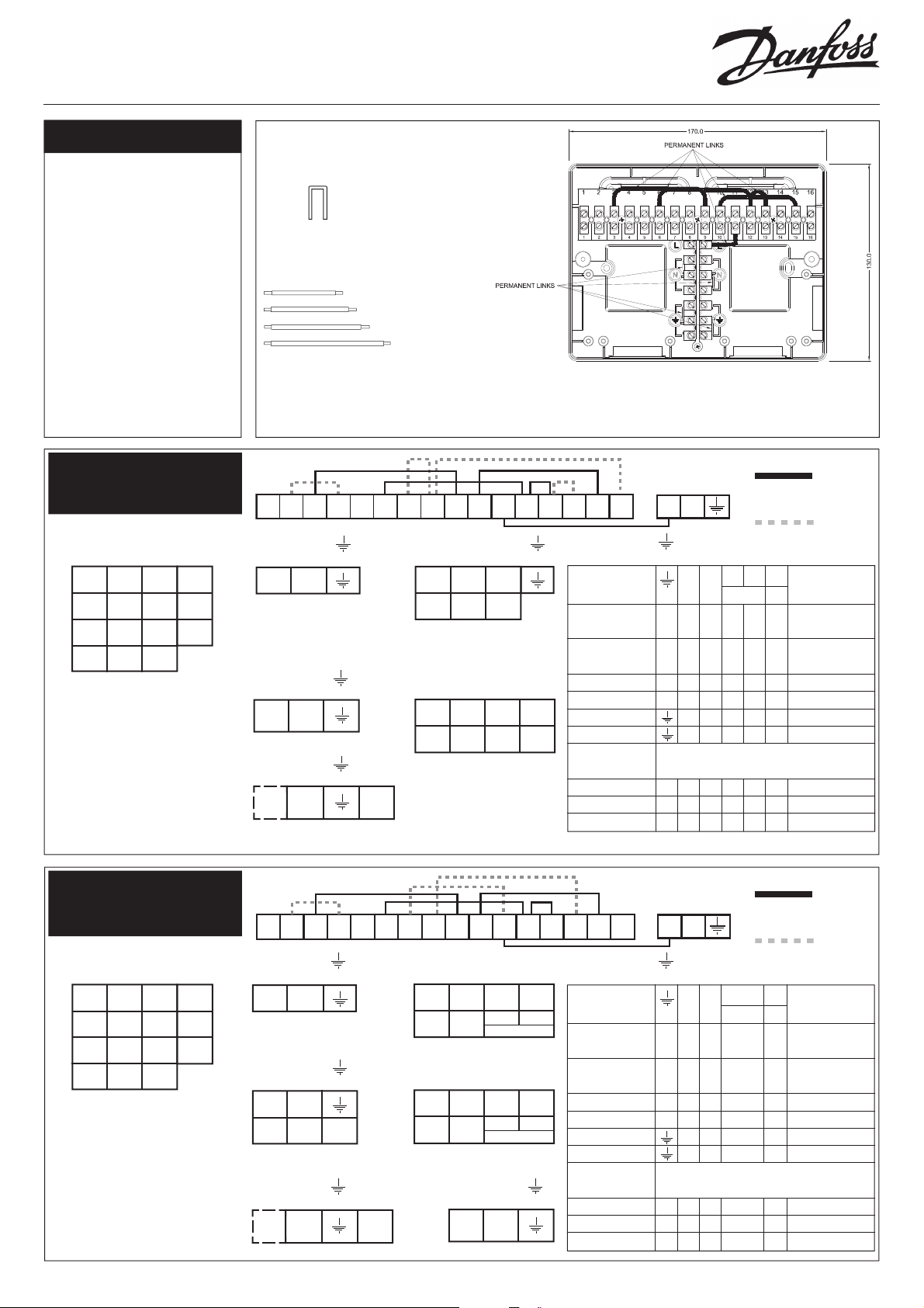
WC4/B Wiring Centre
1
2 3 4 5 6 7 8 9 10 11 12 13 14 15 16
L
N
Wiring Guide
Specifi cation
Terminals: 23 way
Voltage Rating: 230 V 50/60Hz
Current Rating: 10A
Max cable size: 1.5mm
Max. Ambient Temperature: 55°C
Enclosure Rating: IP30
Pollution Control Situation: Normal
Dimensions: 170 mm wide
130 mm high
39 mm deep
Complies with BS6220
2
1. Fully Pumped System,
3-Port Mid-Position
Valve.
3 2 N
¨
¨
¨
1 2 4
L 3 N
L* 1 N
COM CALL N
ROOM THERMOSTAT
* Link terminals L and
Com in the RET230P for
correct operation. (See
thermostat instructions
for further information).
** Refer to Boiler wiring
information for boilers
with pump overrun.
RMT
230
RET
230
RET
230P*
Movable Links
Preformed (2 off )
Straight Solid Core (1 off each)
- 1.5mm2 (BS6004),
ends trimmed 7mm.
45mm
70mm
80mm
105mm
The Danfoss Randall 23-way WC4/B Wiring Centre, suited to most popular heating/hot water systems, provides a systemised
and tidy approach to wiring, particularly in respect of cable links and terminal numbers. It has some fi xed and some movable
links and is designed to be wall mounted, with cable entry from either the rear or through knock-outs in the rear. The following
wiring connection information covers most popular domestic heating control systems.
A. Permanent Links
B. Links to be made by
installer
L N
¨
¨
¨
L N
MAINS SUPPLY
(Fuse 3A)
13 N
¨
¨
¨
L N
** PUMP
L N 12
¨
¨
¨
Perm N Sw.
L L
** BOILER
15 14 16
¨
1 2 3
COM CALL SAT
ATC CYLINDER
THERMOSTAT
4 N 7 6
¨
Wh/ Blue Gr. Or.
Br.
HTG. N HW. Sw.
L OFF L
HS3 MID-POS. VALVE
¨
¨
¨
¨
¨
¨
PROGRAMMER N L OFF ON ON LINKS
WATER HTG
CP715 Si, FP715 Si - N L 1 3 4 -
& TP9000
SET3M, SET 3E - N L 3 1 4 L, 2 & 5
& FP975
SET2E - N L - 1 4 L-2, 1-5
¨
102, 102E5, 102E7 - N L - 1 2 L-3
4033 7 6 5 4 2 1-6
3060 & 3020P 7 6 - 4 2 -
TIMESWITCH N.B. WHEN USING UNITS BELOW LINK 11-9 ON
WIRING CENTRE
103, 103E5, 103E7 - N L - 1 - L-3
TS715 Si - N L - 4 - L-1
SET1E & TS975 - N L - 4 - L-5
N 11 8 10 9
¨¨¨¨¨
¨
2. Fully Pumped System,
2 x 2-Port Spring Return
¨
ller
¨
RMT
230
RET
230
RET
230P*
L N
¨
¨
L N
MAINS SUPPLY
(Fuse 3A)
15 14
¨
¨
1 2
COM CALL
ATC CYLINDER
THERMOSTAT
L N 12
¨
¨
Perm N Sw.
L L
** BOILER
Zone Valves.
3 2 N
¨
1 2 4
L 3 N
L* 1 N
COM CALL N
ROOM THERMOSTAT
* Link terminals L and
Com in the RET230P for
correct operation. (See
thermostat instructions
for further information).
** Refer to Boiler wiring
information for boilers
with pump overrun.
¨
¨
¨
4 N 6 7
¨
Brn. Blue Or. Gr.
Motor N OUT IN.
L Aux. Sw.
HP22, 2-PORT HTG VALVE
8 N 6 7
¨
Brn. Blue Or. Gr.
Motor N OUT IN.
L Aux. Sw.
HP22, 2-PORT DHW VALVE
13 N
¨
L N
** PUMP
¨
¨
¨
¨
¨
¨
A. Permanent Links
B. Links to be made by
installer
N 11 10 9
¨
PROGRAMMER N L ON ON LINKS
WATER HTG
CP715 Si, FP715 Si - N L 3 4 -
& TP9000
SET3M, SET 3E - N L 1 4 L, 2 & 5
& FP975
¨
SET2E - N L 1 4 L-2, 1-5
102, 102E5, 102E7 - N L 1 2 L-3
4033 7 6 4 2 1-6
3060 & 3020P 7 6 4 2 -
TIMESWITCH N.B. WHEN USING UNITS BELOW LINK 11-9 ON
WIRING CENTRE
103, 103E5, 103E7 - N L 1 - L-3
¨
TS715 Si - N L 4 - L-1
SET1E & TS975 - N L 4 - L-5
¨
¨
¨
¨
¨
1
Page 2
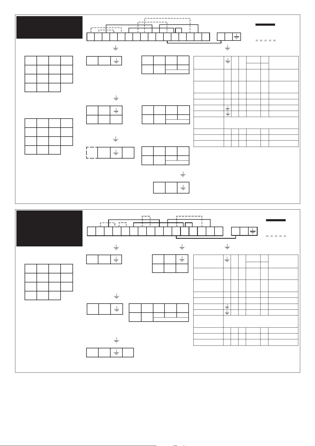
3. Fully Pumped System,
1
2 3 4 5 6 7 8 9 10 11 12 13 14 15 16
L
N
1
2 3 4 5 6 7 8 9 10 11 12 13 14 15 16
L
N
3 x 2-Port Spring Return
Zone Valves.
A. Permanent Links
B. Links to be made by
installer
3 2 N
¨
¨
¨
¨
RMT
230
RET
230
RET
230P*
RMT
230
RET
230
RET
230P*
1 2 4
L 3 N
L* 1 N
COM CALL N
ROOM THERMOSTAT
(Zone 1)
3 1 N
¨
¨
1 2 4
L 3 N
L* 1 N
COM CALL N
ROOM THERMOSTAT
(Zone 2)
* Link terminals L and
Com in the RET230P for
correct operation. (See
thermostat instructions
for further information).
L N
¨
¨
¨
L N
MAINS SUPPLY
(Fuse 3A)
15 14
¨
¨
¨
1 2
COM CALL
ATC CYLINDER
THERMOSTAT
L N 12
¨
¨
¨
Perm N Sw.
L L
** BOILER
** Refer to Boiler wiring
information for boilers
with pump overrun.
4 N 6 7
¨
Brn. Blue Or. Gr.
Motor N OUT IN.
L Aux. Sw.
HP22, 2-PORT HTG VALVE
(Zone 1)
5 N 6 7
Brn. Blue Or. Gr.
Motor N OUT IN.
L Aux. Sw.
HP22, 2-PORT HTG VALVE
(Zone 2)
8 N 6 7
¨
Brn. Blue Or. Gr.
Motor N OUT IN.
L Aux. Sw.
HP22, 2-PORT DHW VALVE
¨
¨
¨
¨
¨
13 N
¨
L N
** PUMP
¨
¨
¨
¨
N 11 10 9
¨
PROGRAMMER N L ON ON LINKS
WATER HTG
CP715 Si, FP715 Si - N L 3 4 -
& TP9000
SET3M, SET 3E - N L 1 4 L, 2 & 5
& FP975
SET2E - N L 1 4 L-2, 1-5
102, 102E5, 102E7 - N L 1 2 L-3
¨
4033 7 6 4 2 1-6
3060 & 3020P 7 6 4 2 -
TIMESWITCH N.B. WHEN USING UNITS BELOW LINK 11-9 ON
WIRING CENTRE
103, 103E5, 103E7 - N L 1 - L-3
TS715 Si - N L 4 - L-1
SET1E & TS975 - N L 4 - L-5
¨
¨
¨
¨
¨
¨
¨
4. Gravity DHW and
Pumped Heating,
one 2-Port Spring
Return Zone Valve in
DHW.
3 2 N
¨
¨
¨
1 2 4
L 3 N
L* 1 N
COM CALL N
ROOM THERMOSTAT
(Zone 1)
* Link terminals L and
Com in the RET230P for
correct operation. (See
thermostat instructions
for further information).
230P*
RMT
230
RET
230
RET
L N
¨
¨
L N
MAINS SUPPLY
(Fuse 3A)
5 N
¨
¨
L N
PUMP
L
N 12
¨
¨
Perm
N L
L
BOILER
15 8
¨
1 2
COM CALL
ATC CYLINDER
THERMOSTAT
7 N 4 14 13
¨
¨
¨
Brn. Blue Wh. Gr. Or.
Motor N N/C N/O COM
L Aux. Sw.
HP28C DHW VALVE
¨
¨
¨
¨
¨
¨
A. Permanent Links
B. Links to be made
by installer
N 11 10 9
¨
¨
¨
PROGRAMMER N L ON ON LINKS
WATER HTG
CP715 Si, FP715 Si - N L 3 4 -
& TP9000
SET3M, SET 3E - N L 1 4 L, 2 & 5
& FP975
SET2E - N L 1 4 L-2, 1-5
102, 102E5, 102E7 - N L 1 2 L-3
¨
4033 7 6 4 2 1-6
3060 & 3020P 7 6 4 2 -
TIMESWITCH N.B. WHEN USING UNITS BELOW LINK 11-9 ON
WIRING CENTRE
103, 103E5, 103E7 - N L 1 - L-3
TS715 Si - N L 4 - L-1
SET1E & TS975 - N L 4 - L-5
¨
¨
¨
2
Page 3

5. Fully Pumped System,
3-port mid-position
valve with 2-channel
programmer and
wireless dial setting
room and hot water
thermostat
A. Permanent Links
WC4B
B. Links to be made by installer
123456789101112131415161718 LN
N L 3 15 2 14 16
¨
¨
NL123456
L N 12
¨
Perm N Sw.
L L
BOILER
RX Channel Assignment
Channel 1 Heating Channel 2 Hot Water
6. Fully Pumped System,
3-port mid-
position valve with
programmable
heating and hot water
thermostats.
¨
RX2C
¨
¨
¨
¨
WC4B
¨
¨
¨
NL8 109
¨
¨
¨
¨
¨
NL1234
FP715Si
13 N
¨
¨
¨
L N
PUMP
4N76
¨
White
Blue Grey Orange
Brown
Heating
N
L
L N
¨
L N
MAINS SUPPLY
A. Permanent Links
B. Links to be made by installer
123456789101112131415161718 LN
¨
HS3
¨
HW
Off SWL
¨
¨
¨
NL 2 1416
¨
¨
¨
¨
¨
NL123456
RX2C
L N 12
¨
¨
¨
¨
Perm N Sw.
L L
BOILER
RX Channel Assignment
Channel 1 Heating Channel 2 Hot Water
13 N
¨
¨
L N
PUMP
¨
4N76
¨
N
HS3
¨
HW
Off SWL
¨
¨
¨
White
Blue Grey Orange
Brown
Heating
L
L N
¨
L N
MAINS SUPPLY
(Fuse 3A)
¨
3
Page 4

7. Fully Pumped System,
2 x 2-port zone valves
with programmable
heating and hot water
thermostats
A. Permanent Links
WC4B
B. Links to be made by installer
123456789101112131415161718 LN
NL 2 14
¨
¨
NL123456
L N 12
¨
Perm N Sw.
L L
BOILER
RX Channel Assignment
Channel 1 Heating Channel 2 Hot Water
8. Fully Pumped System,
2 x 2-port zone
valves with 2-channel
programmer and
wireless dial setting
room and hot water
thermostats
RX2C
¨
8N67
¨
¨
Brown Blue Orange Grey
L N Aux Aux In
HP22 (Hot Water)
L N
¨
¨
L N
MAINS SUPPLY
(Fuse 3A)
A. Permanent Links
B. Links to be made by installer
¨
¨
WC4B
¨
¨
4N67
¨
¨
¨
¨
¨
Brown Blue Orange Grey
L N Aux Aux In
HP22 (Heating)
13 N
¨
L N
PUMP
¨
123456789101112131415161718 LN
¨
¨
¨
NL3152 14
¨
¨
¨
¨
¨
¨
NL123456
RX2C
4N67
¨
¨
Brown Blue Orange Grey
L N Aux Aux In
HP22 (Heating)
¨
N11 109
¨
¨
¨
¨
NL1234
FP715Si
RX Channel Assignment
Channel 1 Heating Channel 2 Hot Water
Danfoss Randall can accept no responsibility for possible errors in catalogues, brochures and other printed material. Danfoss Randall reserves the right to alter its
products without notice. This also applies to products already on order provided that such alterations can be made without subsequent changes being necessary
in specifi cations already agreed.
L N 12
¨
¨
¨
Perm N Sw.
L L
BOILER
¨
13 N
¨
¨
L N
PUMP
¨
Danfoss Randall Ltd.,
Ampthill Road,
Bedford, MK42 9ER
Tel: (01234) 364621 Fax: (01234) 219705
Email: danfossrandall@danfoss.com
Website: www.danfoss-randall.co.uk
8N67
¨
¨
Brown Blue Orange Grey
L N Aux Aux In
HP22 (Hot Water)
L N
¨
L N
MAINS SUPPLY
(Fuse 3A)
¨
¨
¨
¨
¨
4
Part No: 39917v07 12/08
 Loading...