

Page 1
Installation Guide
WattNode
50/60 Hz
-30 – 50°C
(-22°F to 131°F)
L × W × H:
155 mm × 85 mm × 38 mm
(6.1” × 3.35” × 1.5”)
Mounting holes:
Ø5.1mm (0.200”)
CT:
0,333 V A.C. at
rated current
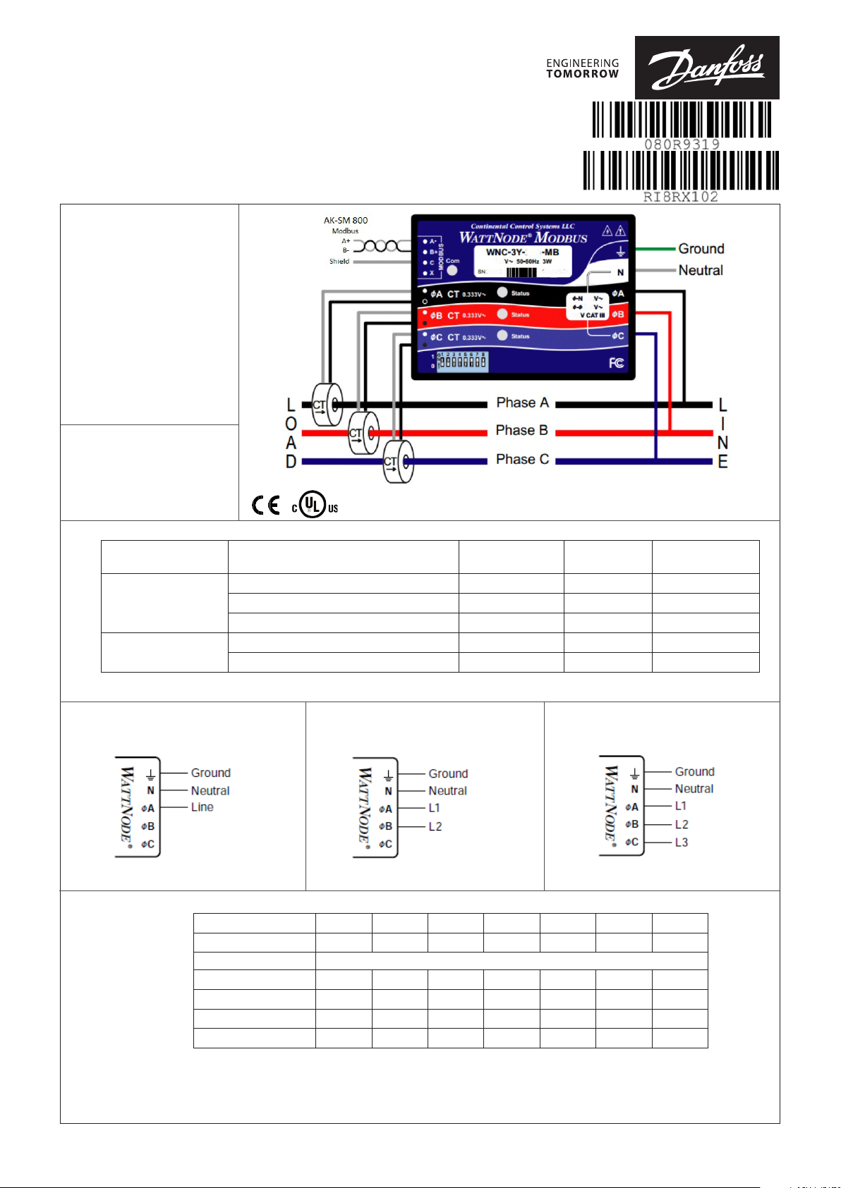
Code Electrical Service Type (Load type)
Single Phase 2-wire with neutral 96 - 138 n.a. N and фA
080Z2144
080Z2146
Single Phase 3-wire with neutral 96 - 138 166 - 276 N and фA
Three Phase 4-wire wye (star) with neutral 96 - 138 166 - 276 N and фA
Single Phase 2-wire with neutral 184 - 264 n.a. N and фA
Three Phase 4-wire wye (star) with neutral 184 - 264 320 - 460 N and фA
Line-to-Neutral
(V A.C.)
Line-to-Line
(V A.C.)
Meter Powered by
Single Phase 2-wire with neutral Single Phase 3-wire with neutral Three Phase 4-wire Wye (star) with neutral
Modbus address
DIP Switch 1 2 3 4 5 6 7
Up (1) Value 1 2 4 8 16 32 64
Address Examples
1 1, Up 0, Down 0, Down 0, Down 0, Down 0, Down 0, Down
1+2+4 = 7 1, Up 1, Up 1, Up 0, Down 0, Down 0, Down 0, Down
4+16 = 20 0, Down 0, Down 1, Up 0, Down 1, Up 0, Down 0, Down
1+2+16+32+64 =115 1, Up 1, Up 0, Down 0, Down 1, Up 1, Up 1, Up
Power on and o the WattNode after setting the Modbus address
© Danfoss | ADAP-KOOL® | 2016.05
RI8RX102 | 1
Page 2
Modbus integration with the AK-SM 800
Step 1: Set the Modbus address (see above, remember to power-cycle the WattNode)
Step 2: Perform a network scan from the AK-SM 800*
*For more information about data communication see document RC8AC and the AK-SM 800 manual. Pay special attention to the
AK-SM 800 manual if devices with a dierent baud rate than 38.400 baud are connected to the AK-SM 800, e.g. the variable speed
compressor type SLV.
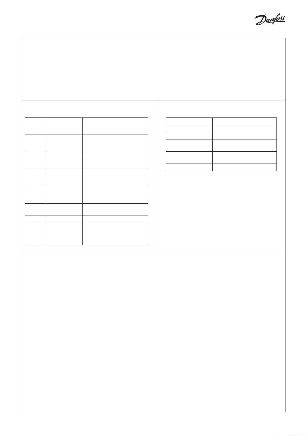
Phase Status LED
All/
Single
phase
All Red, Yellow,
All Red / Green
All OFF WattNode not operating.
All Red for 3 seconds
Single Green No power but line voltage is
Single OFF No voltage on this phase
Single Red continuous
LED Indication Description
Green for 3 x 1
second
continuous
ashing
or more
ashing
Power up sequence
Overvoltage warning.
Line voltage too high.
DISCONNECT power immediately!
Check that the wiring and voltages
are correct
WattNode Error.
If you see this happen repeatedly,
replace the meter
present on this phase
Negative power on this phase
(Reversed CT’s, swapped CT wires
or CT not matching line voltage
phase)
Precautions
Modbus Com LED
LED Indication Description
Green ash Valid packet for this device
Yellow ash Valid packets for dierent device
Red for 1 second Invalid packet (bad baud rate,
Red / Yellow
continuous ashing
Red Address set to 0 (zero)
noise, ...)
Possible address conict (two
devices with same address)
1.1 Only qualied personnel or licensed electricians should install the WattNode meter. The mains voltages can be lethal!
1.2 Follow all applicable local and national electrical and safety
codes.
1.3 The terminal block screws are not insulated. Do not contact
metal tools to the screw terminals if the circuit is live!
1.4 Verify that circuit voltages and currents are within the proper
range for the meter model.
1.5 Use only UL listed or UL recognized current transformers
(CTs) with built-in burden resistors, that generate 0.333 Vac
(333 millivolts AC) at rated current. Do not use current out-
put (ratio) CTs such as 1 amp or 5 amp output CTs: they
will destroy the meter and may create a shock hazard.
1.6 Protect the line voltage conductors to the meter with fuses
or circuit breakers (not needed for the neutral or ground
wires).
1.7 Equipment must be disconnected from the HAZARDOUS
LIVE voltages before access.
1.8 If the meter is not installed correctly, the safety protections
may be impaired.
© Danfoss | ADAP-KOOL® | 2016.05
RI8RX102 | 2
 Loading...