

Page 1
Fitters notes Water valves
Contents Page
Application. . . . . . . . . . . . . . . . . . . . . . . . . . . . . . . . . . . . . . . . . . . . . . . . . . . . . . . . . . . . . . . . . . . . . . . . . . . . . . . . . . . . . . . 47
Identication . . . . . . . . . . . . . . . . . . . . . . . . . . . . . . . . . . . . . . . . . . . . . . . . . . . . . . . . . . . . . . . . . . . . . . . . . . . . . . . . . . . . . 47
Installation . . . . . . . . . . . . . . . . . . . . . . . . . . . . . . . . . . . . . . . . . . . . . . . . . . . . . . . . . . . . . . . . . . . . . . . . . . . . . . . . . . . . . . . 48
Setting . . . . . . . . . . . . . . . . . . . . . . . . . . . . . . . . . . . . . . . . . . . . . . . . . . . . . . . . . . . . . . . . . . . . . . . . . . . . . . . . . . . . . . . . . . . 48
Maintenance . . . . . . . . . . . . . . . . . . . . . . . . . . . . . . . . . . . . . . . . . . . . . . . . . . . . . . . . . . . . . . . . . . . . . . . . . . . . . . . . . . . . . 49
Spare parts . . . . . . . . . . . . . . . . . . . . . . . . . . . . . . . . . . . . . . . . . . . . . . . . . . . . . . . . . . . . . . . . . . . . . . . . . . . . . . . . . . . . . . . 50
Water valves
© Danfoss A/S (AC-DSL/MWA), 10 - 2006 DKRCC.PF.000.G1.02 / 520H1459 45
Page 2

Notes
46 DKRCC.PF.000.G1.02 / 520H1459 © Danfoss A/S (AC-DSL/MWA), 10 - 2006
Page 3

Fitters notes Water valves
Application
Identication
WV pressure-operated water valves are used
in refrigeration systems with water-cooled
condensers to maintain constant condensing
pressure under varying loads.
The water valves can be used for common
refrigerants provided the operating range of the
valves is not exceeded. The WVS can be
used for R717 (ammonia)
Ag0_0001
Danfoss water valve type WVFM consists of a
valve body and bellows housing. The bellows
housing carries a label giving valve type,
operating range and max. permissible working
pressure.
The label also indicates the max. permissible
working pressure on the water side, given as PN
10 in accordance with IEC 534-4.
The direction in which the setting spindle must
be turned for greater or lesser water quantity is
given at the bottom of the valve.
Ag0_0002
Water valve type WVFX consists of a valve body
with setting unit on one side and a bellows
housing on the other.
The bellows housing carries a label giving valve
type, operating range and permissible working
pressure.
All pressures given apply to the condenser side.
Moulded in on one side of the valve body are PN
16 (nom. pressure) and, for example, DN 15 (nom.
diameter), together with kvs 1.9 (valve capacity in
m3/h at a pressure drop of 1 bar).
RA and DA are moulded in on the opposite side
of the valve body.
RA means “reverse acting” and DA means “direct
acting”.
When WVFX is used as a condensing pressure
valve the bellows housing must always be
mounted nearest the DA marking.
Water valves
Ag0_0003
Ag0_0004
© Danfoss A/S (AC-DSL/MWA), 10 - 2006 DKRCC.PF.000.G1.02 / 520H1459 47
Page 4

Fitters notes Water valves
Installation
WVFM and WVFX are installed in the water line,
normally ahead of the condenser, with ow in the
direction of the arrow.
It is a good idea to always install an FV lter
ahead of the water valve to exclude dirt from the
moving parts of the valve.
To prevent vibrations from being transmitted
to the bellows housing the housing must be
connected to the discharge line after the oil
separator, via a capillary tube.
The capillary tube must be connected to the top
side of the discharge line to prevent the backow of oil and perhaps dirt.
WVFM and WVFX 32-40 water valves are normally installed with bellows housing upwards.
Ag0_0005
Ag0_0006
Setting
WVFX 10-25 water valves can be installed in any
position.
WVFM and WVFX water valves must be set
to obtain the required condensing pressure.
Turning the setting spindle clockwise gives lower
pressure, turning it counterclockwise gives higher
pressure.
The scale marks 1 - 5 can be used for coarse
setting. Scale mark 1 corresponds to about 2 bar,
and scale mark 5 corresponds to about 17 bar.
Note that the valve setting range is given for
when the valve begins to open.
The condensing pressure must increase by 3 bar
to fully open the valve.
Ag0_0007
Ag0_0008
48 DKRCC.PF.000.G1.02 / 520H1459 © Danfoss A/S (AC-DSL/MWA), 10 - 2006
Page 5

Fitters notes Water valves
Maintenance
It is a good idea to include water valves in
preventive maintenance because dirt (sludge)
can collect around the moving parts of the valves.
The maintenance routine can include ushing the
water valves, partly to wash out impurities and
partly to be able to “sense” whether the reaction
of valves has become slower.
Ag0_0009
Flushing a WVFM water valve is easiest to
perform if two screwdrivers are inserted under
the setting screw.
The screw can then be levered up to give greater
water ow.
Ag0_0010
WVFX valves can be ushed similarly using two
screwdrivers inserted in the slots on each side of
the setting unit (spring housing) and under the
spring cup.
Levering the screwdrivers down towards the
piping gives greater water ow.
If operating irregularities appear in a water
valve, or if leakage occurs across the valve seat,
dismantle the valve and clean it.
Before dismantling a valve, the pressure must
always be relieved from the bellows housing, i.e.
it must be disconnected from the refrigeration
system condenser.
Before dismantling, screw the setting spring fully
clockwise towards the lowest pressure setting.
The O-ring and remaining seals must always be
replaced after dismantling.
Water valves
Ag0_0011
Ag0_0012
© Danfoss A/S (AC-DSL/MWA), 10 - 2006 DKRCC.PF.000.G1.02 / 520H1459 49
Page 6
Fitters notes Water valves
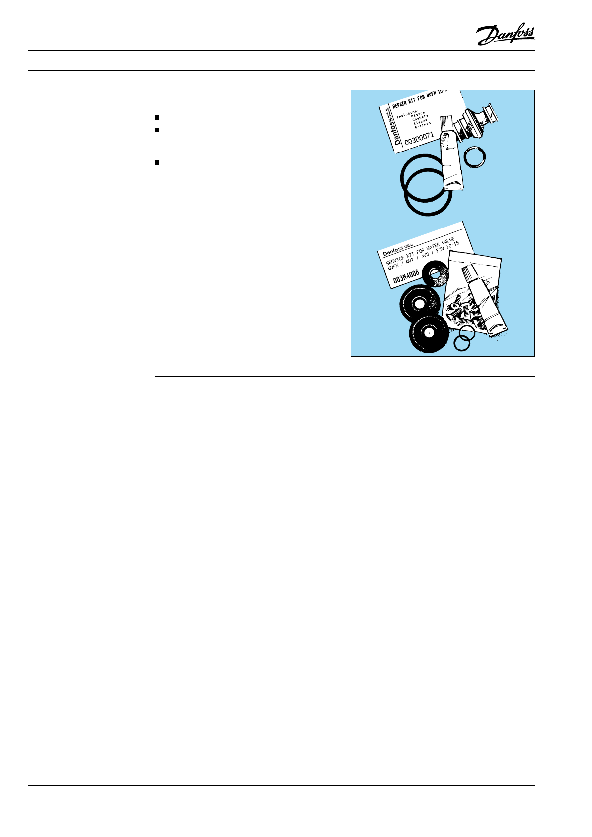
Spare parts
Spare parts for WVFM and WVFX water valves can
be obtained from Danfoss:
one bellows housing.
one service kit (containing spare parts,
gaskets and grease for the water side of the
valve).
A gasket set is also supplied as a spare part for
type WVFM.
The code numbers of spare parts and gasket sets
are given in the spare parts catalogue*.
Ag0_0013
*) Find spare part documentation on http://www.danfoss.com
50 DKRCC.PF.000.G1.02 / 520H1459 © Danfoss A/S (AC-DSL/MWA), 10 - 2006
 Loading...