

Page 1
W895A
Proportional Grade/Steering Controller
BLN-95-8973-2 Issued: April 1996
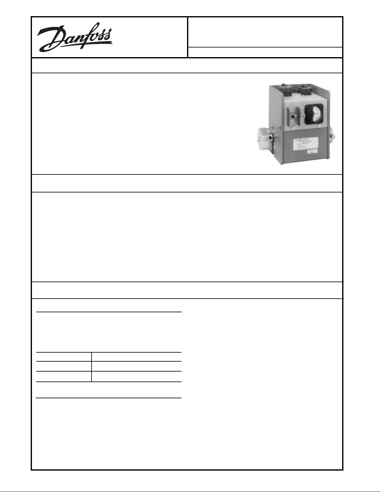
DESCRIPTION
The W895A Proportional Rotary Position Controller is used to provide grade or steering
control of paving, trenching, curbing or similar construction machines. The Controller
uses a follower to sense the grade level or steering direction from a stringline or other
reference surface. When a grade or steering error is sensed, an electrical signal is
provided to the servovalve, such as the KVF, to reposition the machine.
The W895A consists of a microsyn transducer and an amplifier in a single housing.
Modular design with plug-in electrical interconnection allows easy component troubleshooting or replacement.
The W895A may be used with either a right angle stringline follower or a straight tubular
wand. The right angle follower is used for grade control with a stringline; when used with
a firm surface, a skate and ski assembly is attached to a grid arm follower. The straight
tubular wand is used for steering control.
FEATURES
• Easy to install
• Modular design with replacement modules
• Easy to service - single plug-in connector between modules
• May be mounted on either side of equipment
• Adjustable tracking force
• Rugged aluminum housing
• Operator can override with manual control
ORDERING INFORMATION
SPECIFY
1. Model Number W895A. See Table A.
2. Accessories
3. Spare Parts
TABLE A.
ORDER NUMBER DESCRIPTION
W895A1038 12 Vdc, Drives KVF
W895A1053 Without Amp
ACCESSORIES
Order the necessary parts from the list below. See the
following pages for part pictures.
1. KG07002 Steering Follower Wand
2. KG04003 Right Angle Grade Follower
3. K09274 Grid Arm
• Zero-center meter shows deviation from setpoint in RUN
or STANDBY operation
• Shock and vibration resistant
• Reverse polarity and short circuit protection
• Moisture and corrosion resistant
• Adjustable sensitivity
• Dithered output
5. KG06001 Skate Assembly (must be used with the
K09274 Grid Arm)
6. KVF Servovalve
7. ACX104C Rotary Position Sensor
8. KW01013 Cable (two-foot coiled cable that extends to
ten feet. Has right angle connector on one end and
straight connector on the other. Mates with the ten-pin
W895A Connector and an MS3102A18-1P plug (Part
Number K03989)).
9. KW01017 Cable (two-foot coiled cable that extends to
ten feet. Has straight connector on one end and spade
lugs on the other. Mates with the ten-pin W895A Connector and a terminal strip.)
10. KW01001 Cable (two-foot coiled cable that extends to
five feet. Has straight connector on one end and spade
lugs on the other. Mates with the five-pin W895A
Connector and a terminal strip)
4. KG02001 Ski Runner (must be used with the KG06001
Skate Assembly)
© Danfoss, 2013-09 BLN-95-8973-2 1
.
.
Page 2
ORDERING INFORMATION
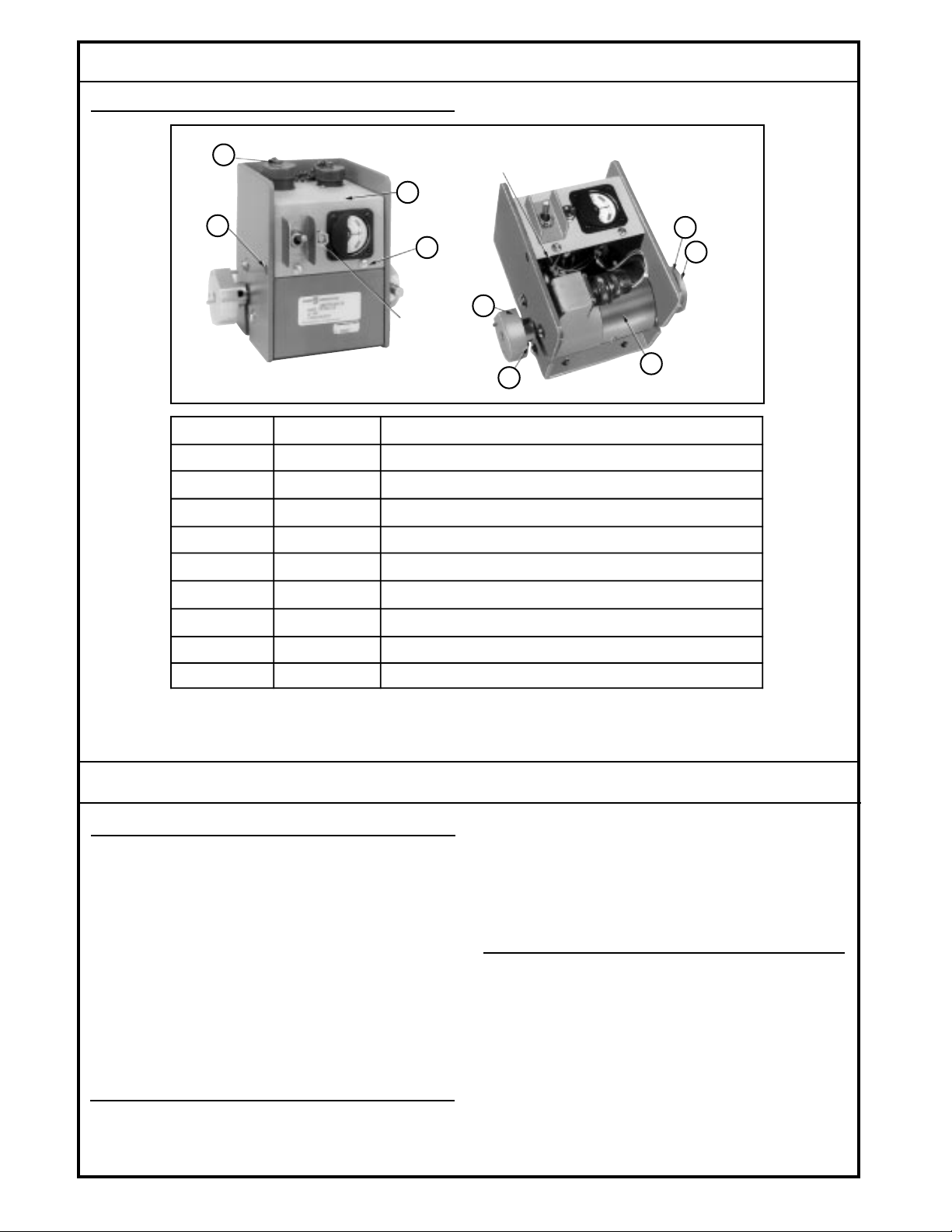
SPARE PARTS IDENTIFICATION
(continued)
4
1
3
GAIN
ADJUSTMENT
ITEM NUMBER PART NUMBER DESCRIPTION
1 K04463 Amplifier Module
2 † Cover Screw (2) 8-32, 1/2 inch
3 † Cover Retaining Bar Mounting Screw (2) Pan Head 8-32, 1/4 inch
4 † Cap and Chain Mounting Screw (2) Round Head 6-32, 5/16 inch
5 K03368 Spring Bias Assembly
6 K04232 Hub Assembly With Channel
GRADE/SLOPE
SWITCH
2
9
7
8
5
6
1181A
7 K04224 Transducer Including MS Connector
8 † Stop Screw, Fillister Head 10-32, 1/2 inch
9 K04228 Hub Assembly With Stop Pins
† Standard hardware items. Obtain locally. Only those parts listed by Part Number should be
ordered from Danfoss. Return the devices for repair if replacing individual parts is
insufficient.
TECHNICAL DATA
ELECTRICAL
INPUT VOLTAGE
11 to 15 Vdc
RATED OUTPUT VOLTAGE
5.8 Vdc (12 Vdc input, 32 ohm, .5 henry load)
GAIN
(with six-inch right angle follower at 45° trailing angle)
1. At minimum gain (full counter-clockwise) no output
voltage for any error input.
2. At maximum gain (full clockwise) .09 inches vertical
deviation yields full drive current to the KVF
Servovalve.
MECHANICAL
SHAFT TORQUE
6.0 inch-grams within 5° of null
NULL
Electrical null is located with the flat edge of the hub at
90 ± 5° from the back (mounting stud) side of the case.
ENVIRONMENTAL
TEMPERATURE RANGE
-40° to 77° C (-40° to 170° F) storage
0° to 77° C (32° to 170° F) operating
SHOCK
50 g for 11 milliseconds. Three shocks in both directions
of the three mutually perpendicular axes for a total of 18
shocks.
SHAFT ROTATION
± 20°
2
BLN-95-8973-2
Page 3
TECHNICAL DATA
(continued)
VIBRATION
Withstands a vibration test designed for mobile equipment controls consisting of two parts:
1. Cycling from 5 to 2000 Hz in each of the three axes.
2. Resonance dwell for one million cycles for each
resonance point in each of the three axes.
Run from 1 g to 46 g's. Acceleration level varies with frequency.
HUMIDITY
After being placed in a controlled atmosphere of 95%
humidity at 49° C (120° F) for 10 days, the sensor will
perform within specification limits.
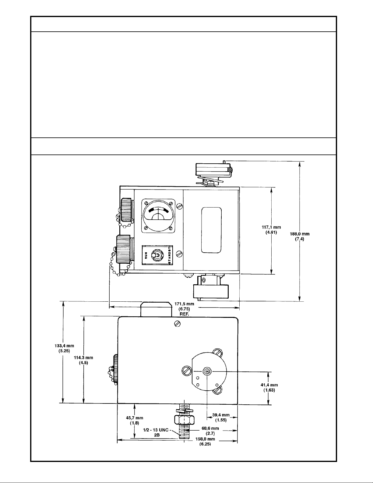
DIMENSIONS
DUST
After being placed in a controlled atmosphere of dust
simulating outdoor conditions for 24 hours, the W895A will
perform within specification limits.
WEIGHT
3.2 kg (7 lbs.)
DIMENSIONS
See Dimension Drawing.
Dimensions of the W895A in Millimeters (Inches).
3
1174
BLN-95-8973-2
Page 4

THEORY OF OPERATION
The amplifying section of the W895A supplies an excitation
of 0.7 Vac (440 Hz square wave) across Pins A and B of the
W895A’s internal MS connector to the transducer. See the
Block Diagram. As the command signal from the stringline or
reference surface moves up/down (grade) or in/out (steering), the W895A’s follower is moved, resulting in rotation of its
shaft. As the rotor moves toward one secondary and away
from the other, the voltage induced in the coil toward the rotor
is increased, the opposite being true of the other secondary.
At the full 20° of travel, the voltage across the secondary
closer to the rotor is 2.3 Vac, while the other voltage is 1.7
Vac.
The ac signals from the secondaries are applied to two bridge
rectifiers in the amplifying section, where each is converted
to dc. At null the voltages across both capacitors are equal.
CONNECTION DIAGRAM
When a change in secondary voltage is introduced, the
voltages across the capacitors are offset, inducing a differential between the reference and lead between the capacitors.
This differential serves as the positive or negative correction
signal that is amplified and then supplied to the servovalves
to close the control loop. Control action drives the machine
to a position such that the sensor error signal to the amplifying section is reduced to null.
Typical Grade Hookup for the W895A Rotary Position Controller.
4
954F
BLN-95-8973-2
Page 5

BLOCK DIAGRAM
Schematic of the Transducer and Amplifier Sections of the W895A.
MOUNTING
The W895A can be mounted on either side of the machine
and in any orientation, depending upon the location of the
grade or steering reference. With the W895A at null and a
follower equivalent to a six-inch radius arm attached to the
sensor at a 45° angle down as referenced to the top surface
of the sensor, the null touch point of the follower will be
approximately 5.5 inches below the center line of the mounting bolt. Figure 1 illustrates the dimension. When the arm is
at a 45° angle up, the touch point is approximately 3.25 inches
above the mounting stud. The follower may also be attached
so that it is parallel to the top surface of the W895A.
Once the mounting location is determined, drill a 14 mm
(9/16-inch) clearance hole for the mounting bolt. Remove the
nut and lockwasher from the mounting bolt through the
clearance hole. Replace the lockwasher and nut and tighten
the nut firmly.
NOTE: W895A must be mounted with connectors up.
1175
The follower may be attached to either hub of the W895A.
The KG04003 Right Angle Grade Follower adapts to almost
any grade application. The attachment can follow a stringline
at a 45° angle above or below the W895A, or it can follow the
stringline horizontally. Figure 2 exhibits one possible way of
attaching the Right Angle Grade Follower. Note the direction
of travel for each.
RIGHT
HUB
Figure 1. Relative Distance to Stringline.
1176
TRAVEL
BREAKAWAY
JOINT
STRINGLINE
Figure 2. Right Angle Grade Follower at Horizontal
Trailing or Leading.
5
1948
BLN-95-8973-2
Page 6

MOUNTING
(continued)
Guide holes on the KG07002 Steering Follower are identified
in Figure 3. This follower may also be attached to either hub
of the W895A. Unlike the Right Angle Grade Follower, it is
mounted vertically for steering applications. See Figure 4.
BREAKAWAY JOINT
STEERING
LEFT HUB
GRADE
RIGHT
1
HUB
THE RIGHT HUB IS DEFINED AS THE ONE WITH
1
THE SPRING BIAS ADJUSTMENT THUMBSCREW
STEERING
RIGHT HUB
LEFT
HUB
1
952B
Figure 3. Guide Hole Identification for the KG07001
Steering Follower.
Other followers include a ski and skate that attach to the
K09274 Grid Arm; Figure 5 shows the ski and a skate
assembly. These followers are used to follow hard reference
surfaces for grade applications. See the Ordering Information for Part Numbers.
After the follower has been installed, adjust the spring bias
adjustment on the right hub so that the follower exerts a slight
tension on the stringline at null. The bias setting controls both
the left and right hub. Note that when the flat of the hub is
parallel to the top surface of the case, the W895A is at null.
RIGHT
HUB
TRAVEL
RIGHT
HUB
1950
Figure 5. Skate and Ski Assembly.
1949
Figure 4. Typical Steering Application. Shaft of the
W895A Must Run Parallel to the Stringline.
6
BLN-95-8973-2
Page 7

WIRING
When used in grade applications, all wiring connections are
made through the larger ten-pin MS connector on the top of
the W895A. It mates with cable number KW01013 as shown
in Connection Diagram. An MS3102A18-1P (Part Number
K03989) connector mates at the other end of this cable to
terminate at the junction board. Another cable, the KW01017,
needs no MS connector interface.
START-UP PROCEDURE
1. Place the RUN/STANDBY switch in the STANDBY
position and energize the electrical system.
2. With the equipment at the correct grade or steering
position, adjust the position of the W895A until the
deviation meter nulls. Lock in position.
3. Adjust the gain potentiometer. Turn the gain potentiometer, located in the face of the W895A, fully clockwise.
Place a nickel between the grade reference surface and
the follower. Adjust the gain potentiometer until the
deviation meter deflects to the red/white division. For
some applications, it may be advantageous to increase
or decrease the gain. Turning the adjustment screw
clockwise will increase the gain, and vice-versa. If the
system oscillates, the gain is too high. If the system is
sluggish and slow to respond, the gain is too low.
If the steering controller is remote from the steering mechanism, electric sensing or steering post position is necessary.
The smaller five-pin connector makes connection to the
steering feedback transducer. The larger ten-pin connector
is used for voltage input and servovalve connections. If the
W895A is attached to the steering mechanism (mechanical
feedback), only the ten-pin connector is used. A KW01001
cable mates with the five-pin connector and terminates in
spade lugs at a junction board. The electrical feedback is
provided by the ACX104C Potentiometer Transducer.
TROUBLESHOOTING
When preliminary investigation of a system malfunction
indicates trouble in the W895A, the following facts should be
kept in mind to determine the specific malfunction:
1. The deviation meter will indicate deviations in grade or
steering whenever power is supplied to the W895A,
regardless of the RUN/STANDBY switch position.
2. In the RUN mode, the amplifier output is connected to
the servovalve. In the STANDBY mode, the amplifier is
not connected to the servovalve.
3. If the gain adjustment on the front panel is turned fully
counter-clockwise (i.e., minimum gain), the position of
the follower will not affect the amplifier or servovalve.
The unit is effectively shut off.
4. Preliminary checks should include examination of the
cables and leads for damaged or broken wires. Examine areas where shorting may occur, and check the
power supply to be sure it is greater than 11 Vdc.
TROUBLESHOOTING PROCEDURE
1. With the W895A turned off, check to see if the meter
operates as the follower is slightly raised or lowered.
Raising or lowering the follower approximately the thickness of a nickel should deflect the indicator to the red/
white division on the meter when the gain potentiometer
is at full clockwise rotation.
2. If the meter operates correctly, check for power output at
the servovalve with the RUN/STANDBY switch in RUN
position. Raising or lowering the follower should cause
a voltage change to about 6 volts before the follower
reaches the stop.
3. If the meter of the W895A does not operate, recheck the
cable for damage or breaks. Replace cables that show
damage. Cables that have been badly pinched or kinked
may have shorted or broken leads.
5. A SLOPE/GRADE switch located on the printed circuit
board of the amplifier module must always be in the
GRADE position if connector Pins C and D are the valve
connections.
4. Check the power supply to be sure that voltage is more
than 11 Vdc. If the voltage supply is adequate, check
voltage at the W895A’s larger connector between Pins
A (-) and B (+) to be sure that cable wiring is not broken
(see Pin Identification Drawing).
5. If power is available, unplug the large connector and
check the meter by momentarily placing 12 Vdc across
Pins C and D on the W895A’s larger connector. The
meter should deflect fully to one side. Reverse polarity
and the meter should deflect to the other side. Be sure
the RUN/STANDBY switch is in the RUN position. If the
meter does not respond when 12 Vdc is applied to Pins
C and D, apply 12 Vdc to Pins E and F. If the meter
responds, the internal SLOPE/GRADE switch (see
Spare Parts Identification Drawing) is in the SLOPE
position and should be switched. If the meter does not
operate, replace the amplifier.
7
BLN-95-8973-2
Page 8

TROUBLESHOOTING PROCEDURE
(continued)
6. If power is available at the W895A and the meter
operates correctly, remove the cover and check the
wiring of the transducer (see Connection Diagram) for
continuity. Remove the plug from the socket on the
transducer so that the pins are accessible. A circuit
should be complete between Pins A and B, C and D, and
E and F on the transducer. There should be approximately 5 ohms between A and B, and 160 ohms between
C and D or E and F (see Pin Identification Drawing). The
circuit should be open between Pins A and F, A and D,
and D and F, as well as between each pin and ground.
If the transducer wiring has a short or break, the transducer should be replaced. If the transducer wiring is not
shorted or broken and the W895A does not function,
replace the amplifier.
C
D
B
A
F
E
JI
D
C
E
G
H
A
B
KEY
A
F
B
C
D
E
1180
Pin Identification for Large Connector On Top of W895A
(Ten-Pin), Small Connector On Top of W895A (Five-Pin)
and Transducer Connector. The Socket Connector
Leads are a Mirror Image of the Pin Identification (Lettered Counter-clockwise).
CUSTOMER SERVICE
NORTH AMERICA
ORDER FROM
Danfoss (US) Company
Customer Service Department
3500 Annapolis Lane North
Minneapolis, Minnesota 55447
Phone: (763) 509-2084
Fax: (763) 559-0108
DEVICE REPAIR
For devices in need of repair or evaluation, include a
description of the problem and what work you believe
needs to be done, along with your name, address and
telephone number.
RETURN TO
Danfoss (US) Company
Return Goods Department
3500 Annapolis Lane North
Minneapolis, Minnesota 55447
EUROPE
ORDER FROM
Danfoss (Neumünster) GmbH & Co.
Order Entry Department
Krokamp 35
Postfach 2460
D-24531 Neumünster
Germany
Phone: 49-4321-8710
Fax: 49-4321-871-184
8
BLN-95-8973-2
 Loading...