

Page 1
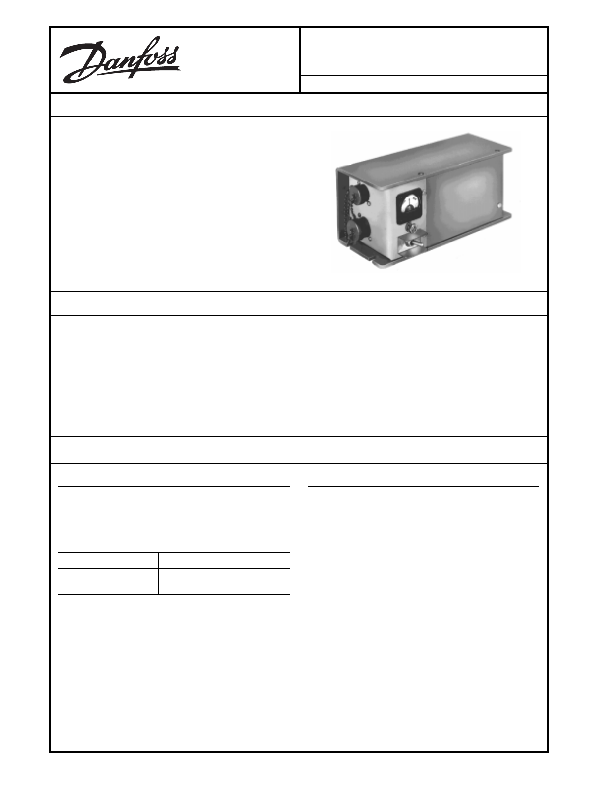
DESCRIPTION
The W894A Proportional Level Controller provides automatic slope control of paving, curbing, grading and similar
mobile equipment. The Controller measures deviation from
a gravity reference and supplies a two-wire output for driving
a servovalve such as the MCV113. The W894A operates in
12 Volt electrical systems.
Two modules are housed in the case of the Controller with
plug-in electrical interconnections. The transducer sensing
module electromagnetically measures the deviation of the
equipment it is mounted on from a gravity reference. The
amplifier module accepts the signals from the slope sensing
module and uses the deviation to provide a corrective output
to keep the equipment at the prescribed slope.
FEATURES
W894A
Proportional Level Controller
BLN-95-8974-5 Issued: March 1992
• Rugged aluminum housing
• Adjustable sensitivity
• RUN/STANDBY switch permits operator to switch to
manual control
• Deviation meter with zero center shows deviation from
setpoint in RUN or STANDBY positions
ORDERING INFORMATION
SPECIFY
1. Model Number W894A. See Table A.
2. Accessories
TABLE A.
ORDER NUMBER DESCRIPTION
W894A1053 12Vdc, Drives MCV113
Hot Side Switching
• Reverse polarity and short circuit protection
• Moisture and corrosion resistant
• Accepts a remote slope setpoint adjuster
• Withstands vibration and shock
ACCESSORIES
Order the necessary parts from the list below:
1. MCV113 Servovalve
2. Q625A Remote Setpoint (hand-held setpoint with integral coiled cord and MS connector).
3. Q625A Remote Setpoint (panel-mount setpoint with terminal strip).
4. KW01001 Cable (two-foot coiled cable that extends to
ten feet. Has straight connector on one end and spade
lugs on the other. Mates with the five-pin W894A connector and the panel-mount Q625A Remote Setpoint)
5. KW01013 Cable (two-foot coiled cable that extends to
ten feet. Has right angle connector on one end and
straight connector on the other. Mates with the ten-pin
W894A connector and an MS3102A18-1P plug).
6. KW01012 Cable (four-foot coiled cable that extends to
twenty feet. Has right angle connector on one end and
straight connector on the other. Mates with the ten-pin
W894A connector and an MS3102A18-1P plug).
© Danfoss, 2013-09 BLN-95-8974-5 1
Page 2
TECHNICAL DATA
ELECTRICAL
INPUT VOLTAGE
11 to 15 Vdc
OUTPUT VOLTAGE
5.4 to 6.2 Vdc with a 12 Vdc input into a 32 ohm load. A
null meter reading at the red/white division indicates a 3
Vdc output.
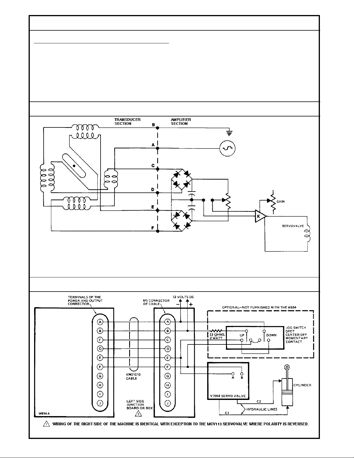
BLOCK DIAGRAM
POWER CONSUMPTION
4.5 watts maximum
PROPORTIONAL GAIN
With gain potentiometer set to maximum, gain will be 1.7
to 2.7 Vdc per 0.3% slope error input.
Schematic of Transducer and Amplifier Sections of the W894A.
CONNECTION DIAGRAM
1183
BLN-95-8974-5
Typical System Connections.
2
206C
Page 3

DIMENSIONS
1182
Dimensions of the W894A in Millimeters (Inches).
THEORY OF OPERATION
The amplifier section of the W894A supplies an excitation of
1.4 V-ac (440 Hz square wave) across Pins A and B of the
W894A’s internal MS connector to the transducer. See the
Block Diagram. As the machine is tilted off the proper slope,
the rotor rotates with respect to the secondary coils. As the
rotor moves toward one secondary and away from the other,
the voltage induced in the coil toward the rotor is increased,
the opposite being true of the other secondary. At the full
10%-from-null slope (the rated maximum range), the voltage
across the secondary closer to the rotor is 5.3 V-ac, while the
other voltage is 4.2 V-ac.
ENVIRONMENTAL
OPERATING TEMPERATURE
-18° to 77° C (0° to 170° F)
STORAGE TEMPERATURE
-40° to 77° C (-40° to 170° F)
HUMIDITY
After being placed in a controlled atmosphere of 95%
humidity at 49° C (120° F) for 10 days, the W894A will
perform within specification limits.
RAIN
After being showered from all directions by a high
pressure hose down, the W894A will perform within
specification limits. This test fulfills NEMA 4 specifications.
The ac signals from the secondaries are applied to two
bridge rectifiers in the amplifier section, where each is
converted to dc. At null the voltages across both capacitors
are equal. When a change in secondary voltage is introduced, the voltages across the capacitors are offset,
inducing a differential between the reference (which may be
a remote setpoint command) and the junction between the
capacitors. This differential serves as the positive or negative correction signal that is amplified and then supplied to
the servovalves to close the control loop. Control action
drives the machine to a position such that the sensor error
signal to the amplifier section is reduced to null.
VIBRATION
Withstands a vibration test designed for mobile equipment consisting of two parts:
1. Cycling from 5 to 2000 Hz in each of the 3 axes.
2. Resonance dwell for one million cycles for each
resonance point in each of the 3 axes.
SHOCK
50 g's for 11 milliseconds. Three shocks in both directions of the 3 mutually perpendicular axes for a total of
18 shocks.
WEIGHT
3.4 Kg (7 pounds, 8 ounces)
DIMENSIONS
See the Dimension Drawing.
3
BLN-95-8974-5
Page 4

CUSTOMER SERVICE
NORTH AMERICA
ORDER FROM
Danfoss (US) Company
Customer Service Department
3500 Annapolis Lane North
Minneapolis, Minnesota 55447
Phone: (763) 509-2084
Fax: (763) 559-0108
DEVICE REPAIR
For devices in need of repair or evaluation, include a
description of the problem and what work you believe
needs to be done, along with your name, address and
telephone number.
RETURN TO
Danfoss (US) Company
Return Goods Department
3500 Annapolis Lane North
Minneapolis, Minnesota 55447
EUROPE
ORDER FROM
Danfoss (Neumünster) GmbH & Co.
Order Entry Department
Krokamp 35
Postfach 2460
D-24531 Neumünster
Germany
Phone: 49-4321-8710
Fax: 49-4321-871-184
4
BLN-95-8974-5
 Loading...