

Page 1
Data sheet
VZL valve - 2/3/4-way
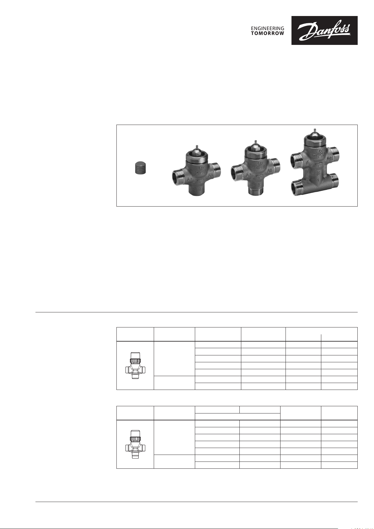
Description
Stem
extension
plug
VZL 4VZL 3VZL 2
Ordering
VZL valves provide a high quality, cost effective
solution for the control of hot and/or chilled
water for fan coil units, small reheaters, and
recoolers in temperature control systems.
The valves are used in combination with:
- AMV(E) 130(H)/140(H) ABNM A5 with
extension plug;
- AMV(E) 13 (SU) and TWA-ZL actuators.
Note:
TWA-ZL thermal a ctuator does not close po rt B.
In case that stem e xtension plug is not used tog ether with AMV(E)
130(H)/140(H) dea d zone in valve close position wil l occur.
2-way valve VZL 2
Picture
DN k
(mm) (m3/h) (bar) Flat End Conex
15
20
VS
0.25 2.5 065Z2070 065Z2040
0.4 2.5 065Z2071 065Z2041
0.63 2.5 065Z2072 065Z2042
1.0 2.0 065Z2073 065Z2043
1.6 2.0 065Z2074 065Z2044
2.5 1.0 065Z2075 065Z2045
3.5 1.0 065Z2076 065Z2046
Main data:
• DN 15, 20
• kVS 0.25-3.5 m3/h
• PN 16
• Temperature:
- Circ. water / glycolic water up to 50 %:
2 … 120 °C
• Reduced kVS on B port (VZL 3 & VZL 4 only)
• Linear characteristic
• Linear bypass on 3 and 4 port valves
• Valves are supplied with screwed plastic
cover for manual operation
• Connections: flat end or conex
• Water quality acc. to VDI 2035 requirements
max. ∆p Code No.
3-way valve VZL 3
Picture
DN
(mm)
15
20
kVS (A - AB) kVS (B - AB)
m3/h
0.25 0.25 2.5 065Z2080
0.4 0. 25 2.5 065Z2081
0.63 0.40 2.5 065Z20 82
1.0 0.63 2.0 065Z2083
1.6 1.0 2.0 065Z 2084
2.5 1.6 1. 0 065Z2085
3.5 2.5 1.0 065Z2086
max. ∆p Code No.
(bar) Flat End
© Danfoss | 2021.11 AI191686478067en-011002 | 1
Page 2
Data sheet VZL valve
Ordering (continued)
Technical data
4-way valve VZL 4
Picture
DN
(mm)
15
20
k
(A - AB) k
VS
0.25 0.25 2.5 065Z2090 065Z2060
0.4 0.25 2.5 065Z2091 065Z2061
0.63 0.4 2.5 065Z2092 065Z2062
1.0 0.63 2.0 065Z 2093 065Z2063
1.6 1.0 2.0 065Z2094 065Z2064
2.5 1.6 1.0 065Z2095 065Z2065
3.5 2.5 1.0 065Z2096 065Z2066
m3/h
(B - AB)
VS
max. Δp
(bar)
Code No.
Flat End Conex
Accessories
Typ e Pipe size DN Description Code No.
Tailpieces with
external thread
Tailpieces for
soldering
Stuffing box 065F0006
Spindle ex tension adapter, 2 mm (5 pieces) 003Z0249
Control characteristic Linear
Control range min. 30:1
Leakage loss, closed valve
Medium Circulation water / Glycolic water up to 50 %
Medium temperature °C 2 … 120
Max. operating pressure bar 16
Stroke mm 2.8
Connection External thread (flat connection (MS 58) or conex)
Materials
Body Brass CuZn40Pb2
Seat cone and stem Brass CuZn39Pb3
Stuffing box EPDM
R /” 15
R ½” 20 003H6902
12 m m 15
15 mm 20 06 5Z7017
Consist of 2 union nuts,
2 tailpieces and 2 gaskets (Ms 58)
Consist of 2 union nuts, 2 solder bushes
and 2 gaskets (Ms 58)
A - AB ≤ 0.05 % of k
B - AB ≤ 1 % of k
VS
VS
065Z7015
065 Z7016
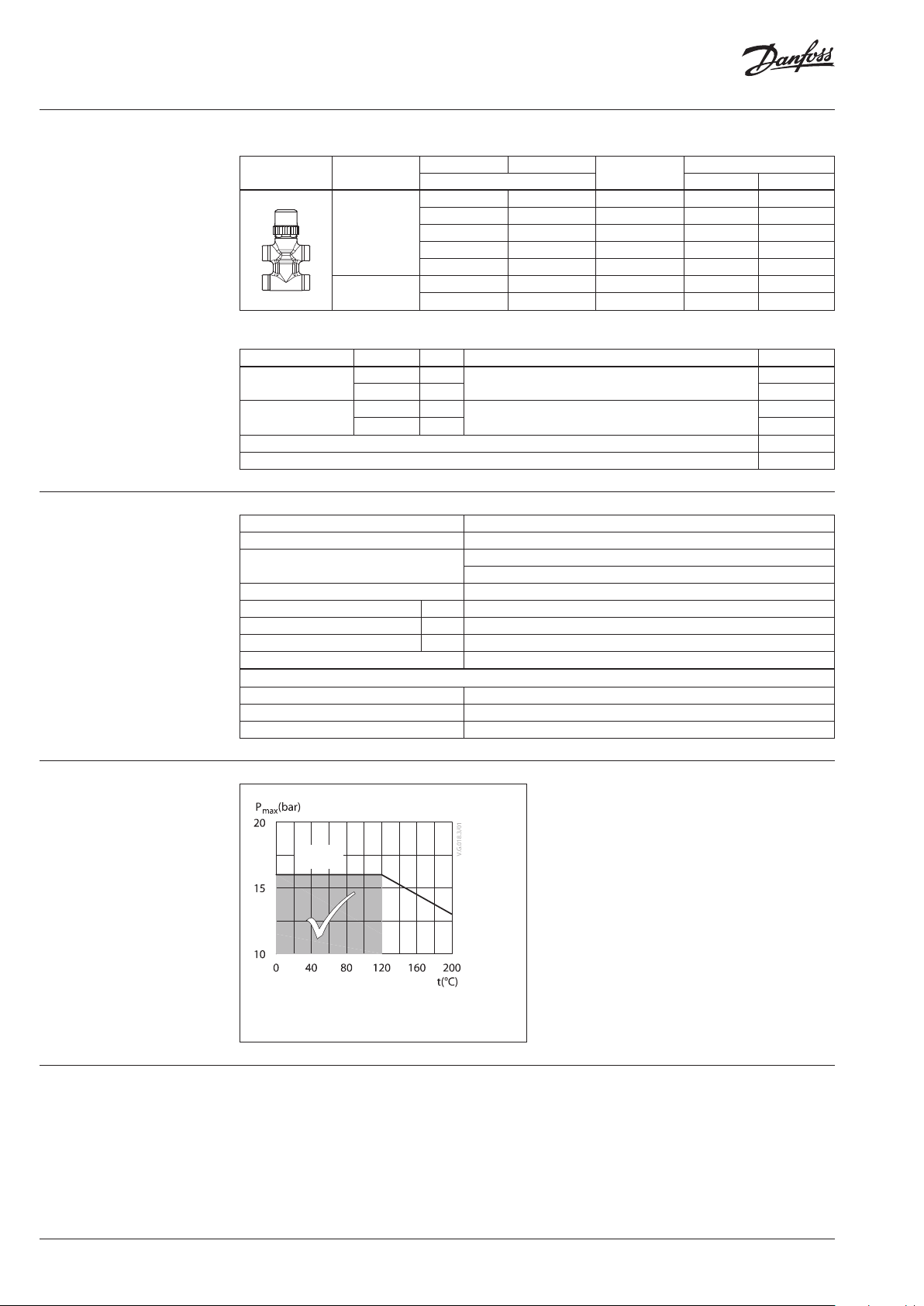
Pressure temperature
diagram
Disposal
PN 16
CuZn4 0Pb2
Maximum allowed operating pressure as a function of
medium temperature (according to EN1092-3)
The valve must be dismantled and the elements
sorted into various material groups before
disposal.
2 | AI191686478067en-011002 © Danfoss | 2021.11
Page 3
Data sheet VZL valve
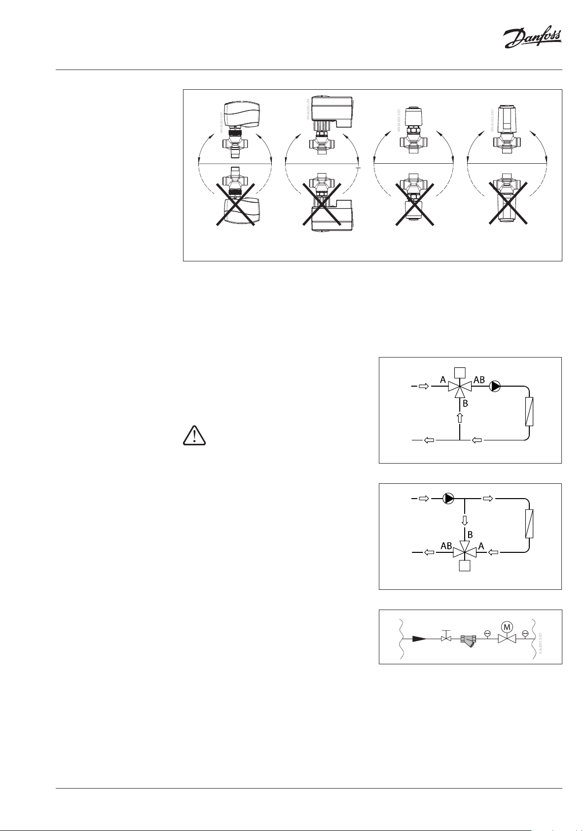
Installation
AMV(E) 130/140,
AMV(E) 130H/140H
AMV(E) 13 (SU)
Valve mounting
Before valve mounting the pipes have to be
cleaned and free from abrasion. Valve must
be mounted according to flow direction as
indicated on valve body. Mechanical loads of the
valve body caused by the pipes are not allowed.
Valve should be free of vibrations as well.
Application schemes for 3-way and 4-way
mixing valves
3-way and 4-way valves are mixing valves
meaning that A and B ports are inlet ports, and
AB port is outlet port (f ig. 1). In case valve should
be used as diverting valve it is a solution to install
valve in return pipe (f ig. 2).
To prevent damages, starting max. p must not
exceed 1 bar for DN 20 and 2/2.5 bar for DN 15,
when installing the valve.
TWA -ZL ABNM-A5
Installation of the valve with the actuator is
allowed in horizontal position or upwards.
Installation downwards is not allowed.
Fig. 1 Mixing valve used in mixing application
Note:
Install a strainer upstream of the valve
(e.g. Dan foss FVR/FV F)
Fig. 2 Mixing valve used in diverting application
AMV(E)
FVR/FVF
AI191686478067en-011002 | 3© Danfoss | 2021.11
Page 4

Data sheet VZL valve
Sizing
Example
Design data:
Flow rate: 0.3 m3/h
System pressure drop: 20 kPa
Locate the horizontal line representing a flow
rate of 0.3 m3/h (line A). The valve authority is
given by the equation:
ΔP
1
N authority, Valve
ΔPΔP
21
Where:
P1 = pressure drop across the fully open valve,
P2 = pressure drop across the rest of the circuit
with a fully open valve
The ideal valve would give a pressure drop equal
to the system pressure drop (i.e. an authority
of 0.5):
If P1 = P2,
ΔP
1
N
=
ΔPΔP
+
5.0
=
21
In this example an authority of 0.5 would be
given by a valve having a pressure drop of
20 kPa at that flow rate (point B).
The intersection of line A with a vertical line
drawn from B lies between two diagonal lines;
this means that no ideally-sized valve is available.
The intersection of line A with the diagonal
lines gives the pressure drops stated by real,
rather than ideal, valves. In this case, a valve with
kVS0.63 would give a pressure drop of 25 kPa
(point C):
authority valve hence
25
0.56
0252
The second-largerst valve, with kVS 1, would give
a pressure drop of 9 kPa (point D):
authority valve hence
9
0.31
0 29
Generally, for a 3 port application, the smaller
valve would be selected (resulting in a valve
authority higher than 0.5, and therefore
improved controllability). However, this will
increase the total pressure and should be
checked by the system designer for compatibility
with available pump head, etc.
The ideal authority is 0.5 with a preferred range
of between 0.4 and 0.7.
Design
to close
A AB
VZL 2 (2 Port)
A
to close A - AB
AB
B
to close A - AB
A AB
B B
VZL 4 (4 Port)VZL 3 (3 Port)
4 | AI191686478067en-011002 © Danfoss | 2021.11
Page 5

Data sheet VZL valve
Dimensions
92
Hh
d
L
AMV(E) 130/140 + VZL 2
+ stem extension plug
92
1
h
c
Hh
AMV(E) 130/140 + VZL 3
+ stem extension plug
121
4.7
Ø5
Stem extension
plug
92
d
L
92
Hh
L
AMV(E) 130/140 + VZL 4
+ stem extension plug
40.5
d
44 .1
1
H
L
AMV(E) 130H/140H + VZL
+ stem extension plug
Valve t ype d
VZL 2 DN 15 G ½” 65 111 117 140 88 93.5
VZL 2 DN 20* G ¾” 77 117 123 146 94 99.5 34.0 0. 47
VZL 3 DN 15 G ½” 65 111 117 140 88 93.5 35.0 0.28
VZL 3 DN 20 G ¾” 77 117 12 3 146 94 99.5 35.0 0.40
VZL 4 DN 15 G ½” 65 111 117 140 88 93.5 40 51.0 0. 39
VZL 4 DN 20* G ¾” 77 117 123 14 6 94 9 9.5 50 65.0 0.59
* conex valves DN 20 - G 1¹/₈” 14 TPI
Tailpieces for soldering
Ød L
G
½” 12 15 0 .11
¾” 15 20 0.17
mm
Weight
2
H
L
AMV(E) 13 SU + VZL
L H H1H2H3H4c h h
mm
3
H
TWA-ZL + VZL
L
-
Tailpieces with external thread
R L Weight
(kg)
G
L
G
Ød
(“) (mm) (kg)
½” ⁄ 23 0 .11
¾” ½ 26 0.17
29.5
4
H
ABNM A5 + VZL
+ stem extension plug
Valve weight
1
(kg)
0.27
47. 5
G
L
R
L
AI191686478067en-011002 | 5© Danfoss | 2021.11
Page 6

Data sheet VZL valve
6 | AI191686478067en-011002 © Danfoss | 2021.11
Page 7

Data sheet VZL valve
AI191686478067en-011002 | 7© Danfoss | 2021.11
Page 8

Data sheet VZL valve
© Danfoss | DCS-SGDPT/SI | 2021.118 | AI191686478067en-011002
 Loading...