

Page 1
Application guidelines
Inverter scroll compressors
VZH hybrid manifold
R410A
http://cc.danfoss.com
Page 2

Page 3

Contents
GENERAL INFORMATION ....................................................................................................4
Scope ...................................................................................................................................................................................... 4
Benets .................................................................................................................................................................................. 4
PRODUCT INFORMATION ...................................................................................................5
Oil management concept ....................................................................................................5
System conguration .......................................................................................................................................................5
Dimensions ...........................................................................................................................8
Tandem .................................................................................................................................................................................. 8
SYSTEM DESIGN ...................................................................................................................9
Design pipe ...........................................................................................................................9
General requirements ...................................................................................................................................................... 9
Suction separator .............................................................................................................................................................11
Oil equalization design .................................................................................................................................................. 11
Design compressor mounting ..........................................................................................12
General requirements ....................................................................................................................................................12
VZH178 Mounting feet ...................................................................................................................................................12
VZH208 Mounting feet ..................................................................................................................................................12
VZH257 / VZH278 Mounting feet ...............................................................................................................................12
VZH301 Mounting feet...................................................................................................................................................13
VZH350 / VZH410 / VZH465 Mounting feet ........................................................................................................... 13
VZH354 Mounting kit ..................................................................................................................................................... 13
Manage operating envelope .............................................................................................14
Requirement ...................................................................................................................................................................... 14
Manage superheat .............................................................................................................15
Requirement ...................................................................................................................................................................... 15
System evaluation ...........................................................................................................................................................15
Test, criteria and solutions ............................................................................................................................................ 15
Manage o-cycle migration ..............................................................................................17
Requirement ...................................................................................................................................................................... 17
System evaluation ...........................................................................................................................................................17
Refrigerant charge limit table ..................................................................................................................................... 17
Manage oil in the circuit ....................................................................................................18
Oil management system for hybrid manifolding ................................................................................................18
Oil management logic ...................................................................................................................................................18
Requirement ...................................................................................................................................................................... 19
System evaluation ...........................................................................................................................................................19
Test, criteria and solutions ............................................................................................................................................ 19
Control logic ...................................................................................................................... 20
Safety control logic requirements .............................................................................................................................20
Cycle rate limit requirements ......................................................................................................................................20
Defrost logic recommendations ................................................................................................................................20
Pump-down logic recommendations ......................................................................................................................21
Assembly line procedure .................................................................................................. 22
Handling ..............................................................................................................................................................................22
ORDERING INFORMATION .............................................................................................. 23
Compressor ordering codes ........................................................................................................................................23
Accessory ordering codes .............................................................................................................................................23
Accessories ......................................................................................................................... 24
Annex ................................................................................................................................. 26
3FRCC.PC.049.A3.02
Page 4
General information
Scope
Benets
The application guideline describes the operating
characteristics, design features and application
requirements for hybrid manifolding of the
Danfoss SH xed-speed compressor and the VZH
inverter compressor in air-conditioning and heat
pump applications.
To ensure proper parallel installation and running
conditions, the following recommendations must
be followed:
A parallel compressor installation refers to a
system of interconnected compressors with a
common suction line and a common discharge
line. The technique of mounting compressors
in parallel is also called manifolding. The hybrid
manifolding in this application guideline refers
to the manifolding of the Danfoss inverter
compressor (VZH) and xed speed compressor
(SH), which has several benets.
• It is essential to respect all the instructions
given in these guidelines; please refer to
the instruction leaet supplied with each
compressor and the application guidelines for
single compressors.
• For additional system components related to
specic application requirements, the supplier
recommendations must always be respected.
The main reason is reduced operating cost
through controlling capacity and power
consumption to a greater extent. This is achieved
by both staggering the compressor switch-on
sequences and regulating the speed of the
inverter compressor which allows the parallel
system to continuously match its power with the
capacity needed.
PRODUCT INFORMATIONSYSTEM DESIGNORDERING INFORMATION GENERAL INFORMATION
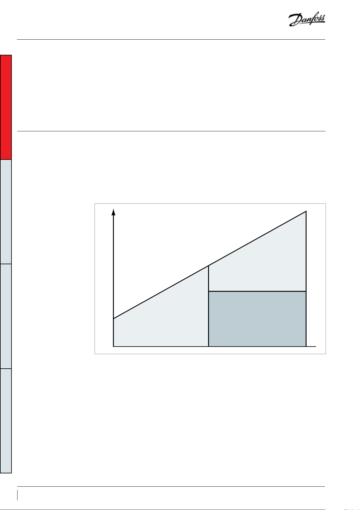
Capacity
Compressor n°1
VZH 25-100 rps
A second reason for manifolding the inverter
compressor and the xed speed compressor is
improved part-load eciency. In the variable
speed+xed speed parallel installation,
the system can run either only the inverter
compressor at lower load or both the inverter and
xed speed compressors at a higher load with the
xed speed compressor operating at 100% load.
Compressor n°1
VZH 25-100 rps
Compressor n°2
xed speed SH
Therefore, it will be possible to achieve a higher
part-load eciency.
Thirdly, the capacity of the hybrid manifolding
system can be widely regulated, for example 10%
to 100%. The continuous capacity regulation
allows for accurate temperature control and a
comfortable indoor environment.
4 FRCC.PC.049.A3.02
Page 5
Oil management concept
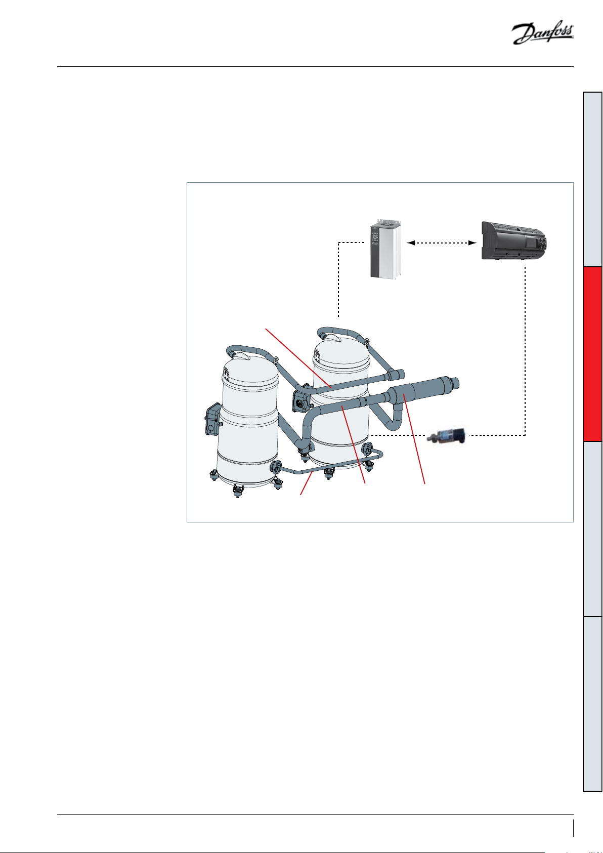
System conguration
Hybrid manifolding systems use the dynamic
system for oil balance. The suction connections
between the two individual compressors are
interconnected by a special suction separator
design that allows most of oil feed into variable
speed compressors.
Discharge line
VZH
SH
An optical-electrical oil level sensor xed in
a variable speed compressor monitors the
compressor oil level.
If the oil level drops below the limit, the OEM
main controller activates the oil management
logic.
Drive
ModBus
OEM main controller
GENERAL INFORMATIONSYSTEM DESIGNORDERING INFORMATION PRODUCT INFORMATION
Oil equalization tube
Optical oil
level sensor
Suction separatorSuction line
5FRCC.PC.049.A3.02
Page 6
Oil management concept
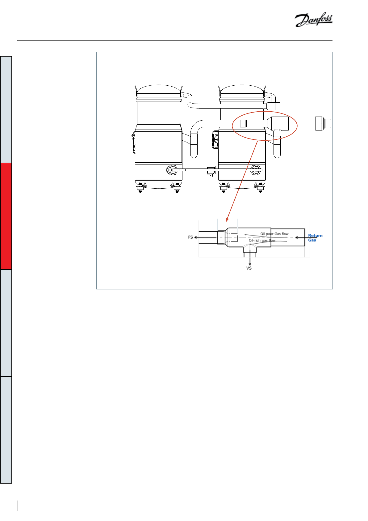
FS VS
GENERAL INFORMATIONSYSTEM DESIGNORDERING INFORMATION PRODUCT INFORMATION
Downstream
compressor
Upstream
compressor
Suction separator (Oil separator/gas restrictor)
The hybrid manifolding system uses the dynamic
system for oil balance.
The suction connections of the two individual
compressors are interconnected by a suction
separator that integrates with the suction oil
separator and the gas restrictor. The variable
speed compressor (VS) is installed in the
upstream position which appears rst on suction
line and xed speed compressor (FS) is installed
on downstream position.
The oil which clings back along the main suction
line is separated by the suction separator which
returns most of the oil in the suction gas to the
upstream compressor. The suction separator
creates a slight pressure drop to ensure lower
sump pressure between two compressors are
well balance when xed speed compressor
is ON and the inverter compressor is running
at maximum speed. When the variable speed
compressor runs at any frequency below
maximum speed, the sump pressure in the xed
speed compressor is lower than the variable
speed compressor, and driven by the sump
pressure dierence, the excess oil from the
variable speed compressor runs into the xed
speed compressor sump.
6 FRCC.PC.049.A3.02
Page 7

Oil management concept
Approved hybrid tandem
congurations and
capacity range
Dierent congurations of hybrid tandems are possible. All VZH models (high/low pressure ratio/
dierent voltage) could be manifolded with xed speed compressors.
Danfoss VSD : VZH compressor DriveTM 380-480 Volt
Model Description
VZH178 VZH088+SH90 68.9 19.6 73.9 21.0
VZH208 VZH088+SH120 77.7 22.1 83.7 23.8
VZH257 VZH117+SH140 97.8 27. 8 105. 2 29.9
VZH278 VZH117+SH161 101.6 28.9 110 .1 31.3
VZH301 VZH117+SH184 106.2 30.2 115 .7 32.9
VZH350 VZH170+SH180 137. 5 39.1 147. 4 41.9
VZH354 VZH170+SH184 137. 0 39.1 146 .0 41.9
VZ H410 V ZH170+SH240 151.9 43.2 164.9 46.9
VZH465 V ZH170 +SH295 164.6 46.8 179. 3 51.0
TR: Ton of Refrigeration Refrigerant: R410A
Standard rating conditions: ARI standard Evaporating temperature: 7.2°C Superheat: 11.1k
Condensing temperature: 54.4°C Subcooling: 8.3k
Subject to modication without prior notication
Data given for motor code G compressor – for full data details and capacity tables, please refer to Coolselector2
www.coolselector.danfoss.com
FS: 50Hz, VS:100Hz FS: 60Hz, VS: 100Hz
kW TR kW TR
GENERAL INFORMATIONSYSTEM DESIGNORDERING INFORMATION PRODUCT INFORMATION
7FRCC.PC.049.A3.02
Page 8
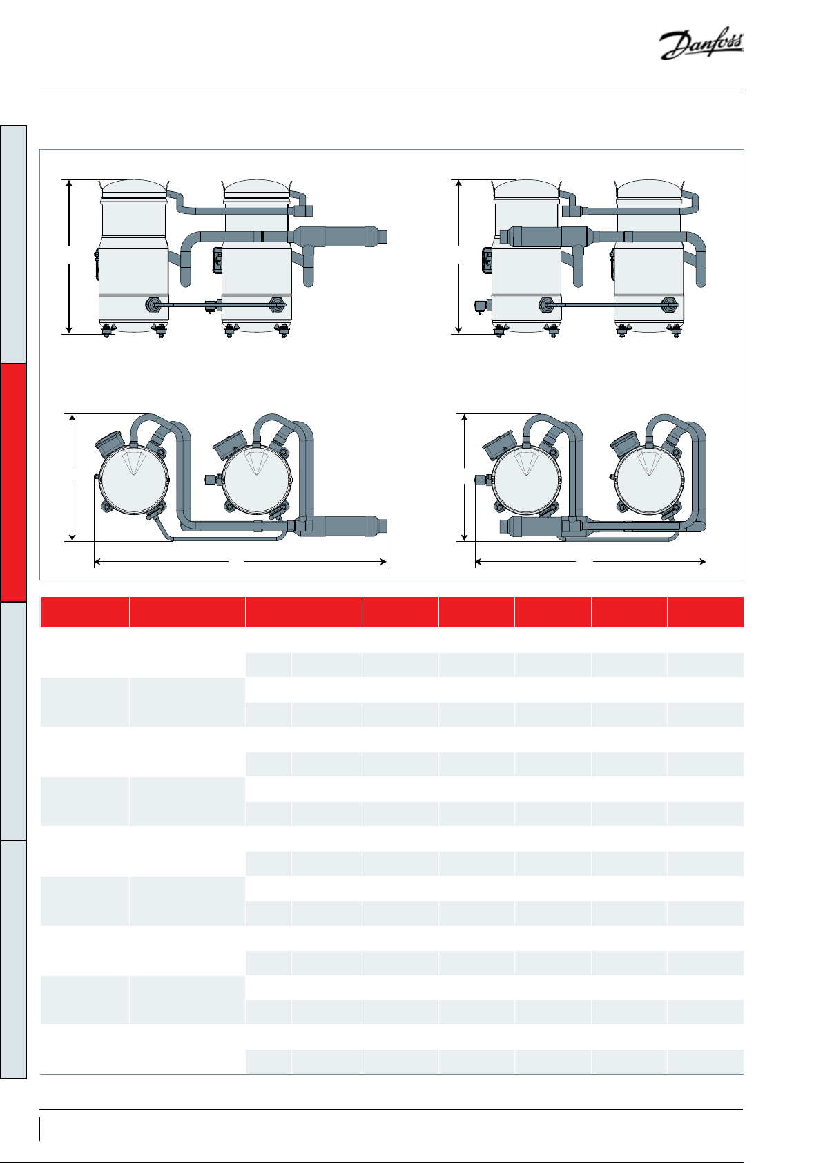
Dimensions
Tandem
H
GENERAL INFORMATIONSYSTEM DESIGNORDERING INFORMATION PRODUCT INFORMATION
D
L
Tandem model Composition
VZH178 VZH088 + SH090
Outline drawing
number
VZH208 VZH088 + SH120
VZH257 VZH117 + SH140
VZH278 VZH117 + SH161
VZH301 VZH117 + SH184
VZH350 VZH170 + SH180
VZH354 VZH170 + SH184
VZ H410 VZH170 + SH240
VZH465 VZH170 + SH295
Tandem congurations are achieved by assembling individual compressors
H
D
L
Suction Discharge L (mm) D (mm) H (mm)
8560108 1"5/8 1"3/8 1011 445 482
8560109 1"5/8 1"3/8 810 445 482
8560104 1"5/8 1"3/8 1011 445 540
8560105 1"5/8 1"3/8 811 445 540
8560106 1"5/8 1"3/8 1024 445 540
8560107 1"5/8 1"3/8 811 445 540
8560106 1"5/8 1"3/8 1024 445 540
8560107 1"5/8 1"3/8 811 445 540
8556183 1"5/8 1"3/8 1116 445 555
8556184 1"5/8 1"3/8 811 445 555
8556181 2"1/8 1"5/8 1233 550 682
8556182 2"1/8 1"5/8 953 550 682
8556188 2"1/8 1"5/8 1241 550 682
8556189 2"1/8 1"5/8 890 550 682
8556181 2"1/8 1"5/8 1233 550 682
8556182 2"1/8 1"5/8 953 550 682
8556181 2"1/8 1"5/8 1233 550 682
8556182 2"1/8 1"5/8 953 550 682
8 FRCC.PC.049.A3.02
Page 9
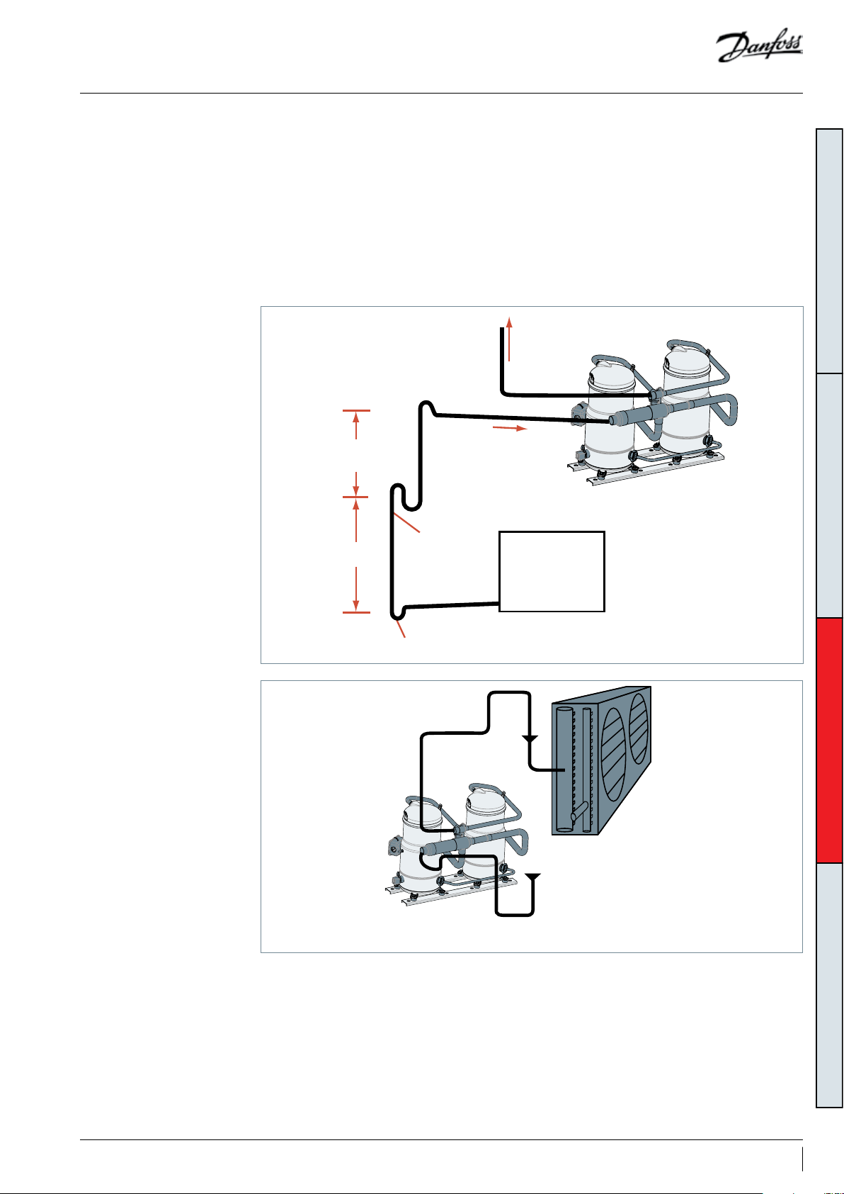
Design pipe
General requirements Proper piping practices should be employed to:
1. Ensure adequate oil return, even under
minimum load conditions (xed speed
compressor o, variable speed compressor
at minimum speed, minimum evaporating
conditions). If minimum refrigerant velocity
cannot be reached, it is strongly recommended
that an oil separator is used. For a validation test,
the see section “Manage oil in the circuit”.
0.5% slope
4 m/s or more
max. 4 m
U-trap, as short as possible
8-12 m/s
max. 4 m
0.5% slope
4 m/s or more
2. Prevent condensed liquid refrigerant from
draining back into the compressor when
stopped (discharge piping upper loop). For
validation tests, see the section “Manage o-cycle
migration”.
General recommendations are described in the
gures below:
GENERAL INFORMATIONPRODUCT INFORMATIONORDERING INFORMATION SYSTEM DESIGN
To condenser
HP
LP
Evaporator
U trap, as short as possible
Upper loop
HP
LP
3D exibility
3. Piping should be designed with adequate
three-dimensional exibility to avoid excess
vibration. It should not be in contact with the
surrounding structure, unless a proper tubing
mount has been installed. For more information
Condenser
on noise and vibration, see the section “Sound
and vibration management” in the application
guideline for Danfoss VZH scroll compressors
(FRCC.PC.023).
9FRCC.PC.049.A3.02
Page 10
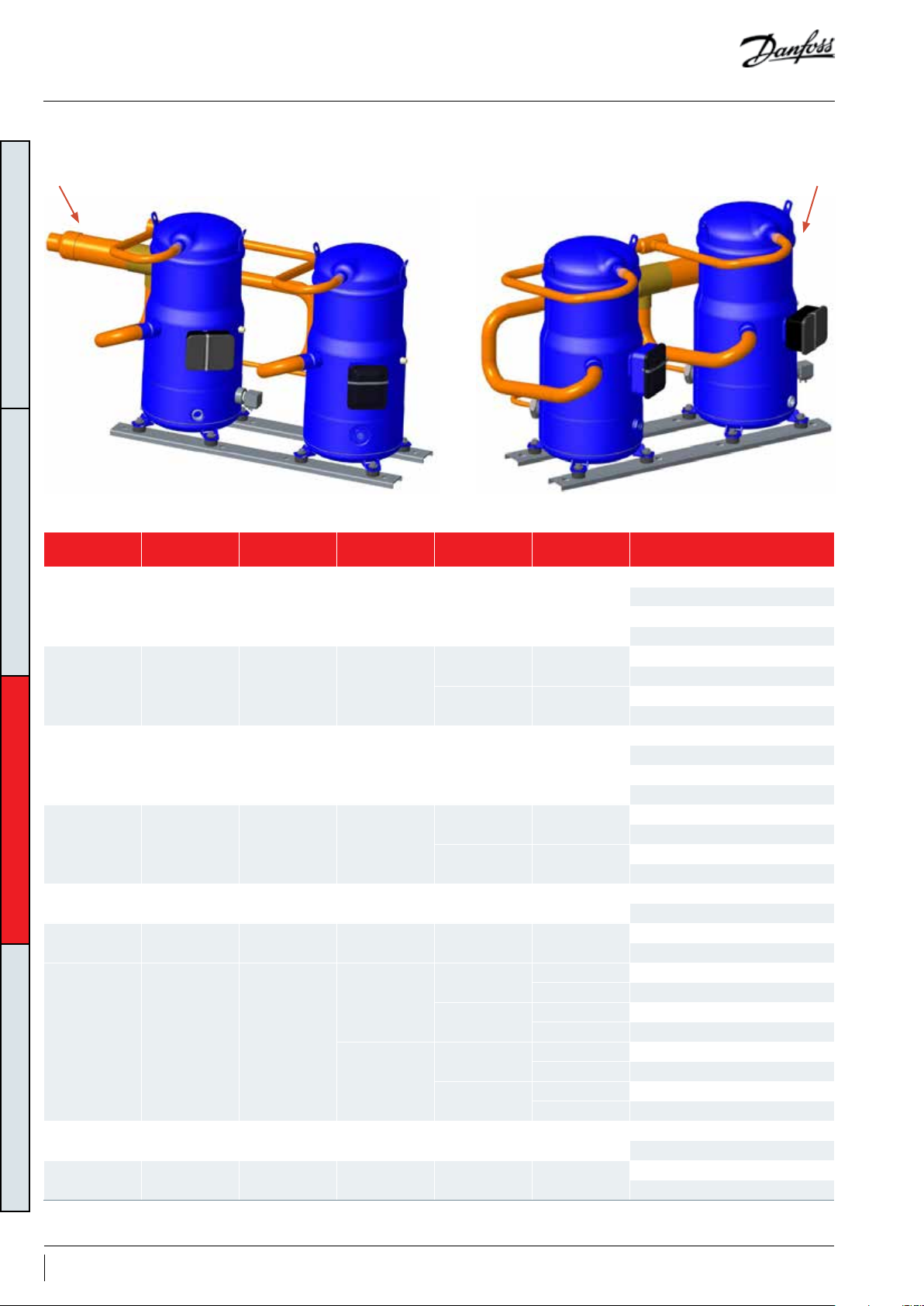
Design pipe
Suction on left Suction on right
GENERAL INFORMATIONPRODUCT INFORMATIONORDERING INFORMATION SYSTEM DESIGN
Variable speedVariable speed
Fixed speed Fixed speed
Fixed speed Variable speed Tandem model Suction direction
SH090 VZH088 VZH178 Left/Right
SH120 VZH088 VZH208 Left/Right
SH14 0 VZ H117 VZH257 Left/Right
SH161 V ZH117 VZH278 Left/Right
SH184 V ZH117 VZH301 Left/Right 50 & 60 120Z0 656
SH180 VZH170 VZH350 Left/Right 50 & 60 120Z0657
SH184 VZH170 VZH354
SH240 VZH170 VZH410 Left/Right 50 & 60 120 Z06 57
SH295 VZH170 VZH465 Left/Right 50 & 60 120 Z0655
Note:
The tandem accessory includes oil equalization kits and oil level sensor. For compressors that need a UL certicate, please order the accessory kit with the 24V oil level sensor.
+
+
+
+
+
+
Left
+
Right
+
+
Hz of FS
compressor
50 120Z0 676
60 12 0Z0675
50 120Z0664
60 120Z0658
50 120Z0666
60 120Z066 5
50 120Z 066 5
60 120Z0 674
50
60
50
60
Suction separator
code
120Z0683 120Z0682 (with 24V oil level sensor)
120Z0683 120Z0681 (with 230V oil level sensor)
120Z0 655 120Z0682 (with 24V oil level sensor)
120Z0 655 120Z0681 (with 230V oil level sensor)
120Z0 687 120Z0682 (with 24V oil level sensor)
120Z0 687 120Z0681 (with 230V oil level sensor)
120Z0 687 120Z0682 (with 24V oil level sensor)
120Z0 687 120Z0681 (with 230V oil level sensor)
Tandem accessory kit code
120Z0653 (with 24V oil level sensor)
120Z0654 (with 230V oil level sensor)
120Z0653 (with 24V oil level sensor)
120Z0654 (with 230V oil level sensor)
120Z0651 (with 24V oil level sensor)
120Z0652 (with 230V oil level sensor)
120Z0651 (with 24V oil level sensor)
120Z0652 (with 230V oil level sensor)
120Z0653 (with 24V oil level sensor)
120Z0654 (with 230V oil level sensor)
120Z0653 (with 24V oil level sensor)
120Z0654 (with 230V oil level sensor)
120Z0653 (with 24V oil level sensor)
120Z0654 (with 230V oil level sensor)
120Z0653 (with 24V oil level sensor)
120Z0654 (with 230V oil level sensor)
120Z0651 (with 24V oil level sensor)
120Z0652 (with 230V oil level sensor)
120Z0649 (with 24V oil level sensor)
120Z0650 (with 230V oil level sensor)
120Z0649 (with 24V oil level sensor)
120Z0650 (with 230V oil level sensor)
120Z0649 (with 24V oil level sensor)
120Z0650 (with 230V oil level sensor)
10 FRCC.PC.049.A3.02
Page 11
Design pipe
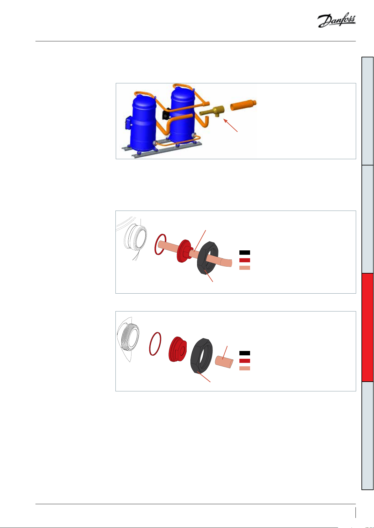
Suction separator
Oil equalization design
The suction connections of the two individual
compressors are interconnected by a suction
separator, which is supplied as an accessory.
The two compressors are connected by a ½" or
¾" oil equalization pipe. To x the oil equalization
connection rotolock, use the adaptor sleeves
½"
Suction separator
and the seal gasket which were included in the
tandem accessory kit.
Model: VZH178-208-257-278-301/354
(SH184 oil equalization line)
GENERAL INFORMATIONPRODUCT INFORMATIONORDERING INFORMATION SYSTEM DESIGN
Tightening torque 100NM
Model: VZH350-410-465/354
(VZH170 oil equalization line)
¾"
Tightening torque 145Nm
Supplied with the compressor
Included in tandem kit
Not supplied
Supplied with the compressor
Included in tandem kit
Not supplied
11FRCC.PC.049.A3.02
Page 12

Design compressor mounting
Tightening torque
General requirements
VZH178 Mounting feet
GENERAL INFORMATIONPRODUCT INFORMATIONORDERING INFORMATION SYSTEM DESIGN
VZH208 Mounting feet
The tandem is xed to the frame using the
exible grommets that are supplied with
The compressors are xed to the frame using
rubber grommets, mounting sleeves, and
washers (supplied with the compressors).
HM 8 bolt
Lock washer
Flat washer
Steel mounting
sleeve
Rubber grommet
Nut
Base plate, frame, etc. with sucient rigidity
Mounting for SH090 and VZH088
15Nm
15 mm
The compressors are xed to the frame using
rubber grommets, mounting sleeves, and
washers (supplied with the compressors).
Because VZH088 is 7 mm smaller than SH120,
in order to ensure that the oil equalization
Tightening torque
HM 8 bolt
Lock washer
Flat washer
Steel mounting
sleeve
Rubber grommet
15Nm
15 mm
the compressor or which are included in the
accessory kit.
connection is at the same level for both
compressors, an additional 7mm rigid spacer
must be added under VZH088 (see drawing. The
7 mm rigid spacer is supplied with the tandem
accessory kit).
Tightening torque
15Nm
Rigid spacer
VZH257 / VZH278
Mounting feet
Nut
Base plate, frame, etc. with sucient rigidity
Mounting for SH120
The compressors are xed to the frame using
rubber grommets, mounting sleeves, and
washers (supplied with the compressors).
Tightening torque
HM 8 bolt
Lock washer
Flat washer
Steel mounting
sleeve
Rubber grommet
Nut
Base plate, frame, etc. with sucient rigidity
Mounting feet
15Nm
15 mm
Mounting for VZH088
12 FRCC.PC.049.A3.02
Page 13

Design compressor mounting
Tightening
torque 21Nm
28mm
HM8 bolt
VZH301 Mounting feet
VZH350 / VZH410 /
VZH465 Mounting feet
The compressors are xed to the frame using
rubber grommets, mounting sleeves, and
washers (supplied with the compressors).
Because VZH117 is 7 mm smaller than SH184,
in order to ensure that the oil equalization
Tightening torque
HM 8 bolt
Lock washer
Flat washer
Steel mounting
sleeve
Rubber grommet
Nut
Base plate, frame, etc. with sucient rigidity
Mounting for SH184
15Nm
15 mm
The compressors are xed to the frame using
rubber grommets, mounting sleeves, and
washers. The VZH mounting kits are supplied
connection is at the same level for both
compressors, an additional 7mm rigid spacer
must be added under VZH117 (see drawing. The
7 mm rigid spacer is supplied with the tandem
accessory kit).
Tightening torque
15Nm
GENERAL INFORMATIONPRODUCT INFORMATIONORDERING INFORMATION SYSTEM DESIGN
Rigid spacer
Mounting for VZH117
with the VZH compressor, and SH mounting kits
are included in the tandem accessory kit.
VZH354 Mounting kit
Tightening
HM 8 bolt
Lock washer
Flat washer
Steel mounting sleeve
Rubber grommet
Nut
Mounting feet
torque 21Nm
Compressor
base plate
28 mm
The compressors are xed on the frame using
rubber grommets, mounting sleeves, washers
(delivered with the compressors).
Tightening
torque 15Nm
Lock washer
Steel mounting
sleeve
Nut
HM8 bolt
Flat
washer
Rubber
grommet
Rigid
spacers
Because SH184 is 14mm smaller than VZH170, in
order to have oil equalization connection at the
same level for both compressors, two additional
7mm rigid spacers must be added under SH184
(See below drawing, two 7mm rigid spacers are
provided in Tandem accessory kit).
HM8 bolt
Tightening
torque 21Nm
28mm
Base plate, frame, etc. with enough rigidity
Mounting for SH184 Mounting for VZH170
13FRCC.PC.049.A3.02
Page 14

Manage operating envelope
Requirement The operating envelope for hybrid manifolding is
shown below, and guarantees reliable operation
of the compressor for steady-state operation.
VZH operating map - 575V/400V/208V (SH 6 K)
75
65
GENERAL INFORMATIONPRODUCT INFORMATIONORDERING INFORMATION SYSTEM DESIGN
55
45
35
25
Condensing temperature (°C)
15
-30 -20 -10 0 10 20
30-90 rps
Evaporating temperature (°C)
High PR Low PR
The steady-state operation envelope is valid for a
suction superheat of between 5K and 30K.
30-90 rps
25-100 rps
Note: red and blue lled area are limited to 30-90 rps
Note: for 380V power input, permitted highest condensing temperature will decrease accordingly:
-High PR: 25-100 rps, condensing temperature from 60°C to 56°C; 30-90 rps, condensing temperature from 68°C to 65°C
-Low PR: 25-100 rps, condensing temperature from 60°C to 56°C; 30-90 rps, condensing temperature from 63°C to 62°C.
Pressure settings R410A
Working range high side bar(g)
Working range low side bar(g) 2.3-11.6
Maximum high pressure safety switch setting* bar(g) 45
Minimum low pressure safety switch setting bar(g) 1.5
Minimum low pressure pump-down switch setting bar(g)
*Maximum allowable pressure on high pressure side according to PED regulation.
LP and HP safety switches must never be bypassed nor delayed and must stop all the compressors.
The LP safety switch auto restart must be limited to ve times within 12 hours.
The HP safety switch must be reset manually.
Depending on application operating envelope, it is necessary to dene the HP and LP limits within the operating envelope and using
the pressure setting table above.
pressure with minimum of 2.3 bar(g)
High PR 13.5-44.5
Low PR 13.5-40
1.5 bar below nominal evaporating
14 FRCC.PC.049.A3.02
Page 15

Manage superheat
Requirement
System evaluation
Basic unit
single exchanger
as evaporator and
condenser
X X Optional Pass liquid ood back test
X - X Recommended
During normal operation, refrigerant enters the
compressor as a superheated vapour. Liquid
ood back occurs when some of the refrigerant
entering the compressor is still in a liquid state.
In the steady-state condition, the expansion
device must ensure a suction superheat of
between 5k and 30k.
Advance unit
Multiple exchangers as evaporator or
condenser (heat-recovery, exchanger,
four-pipe chiller…)
X X Mandatory Pass liquid ood back test
X X Mandatory
Liquid ood back can cause oil dilution and, in
extreme situations, lead to liquid slugging that
can damage compression parts.
GENERAL INFORMATIONPRODUCT INFORMATIONORDERING INFORMATION SYSTEM DESIGN
Tes t
Non-reversible
Reversible
Suction accumulator
Pass liquid ood back test
Pass defrost test
Pass liquid ood back test
Pass defrost test
Test, criteria and solutions
Tes t N o Purpose Test condition Pass criteria Solutions
Liquid ood back testing must be
carried out under expansion valve
threshold operating conditions:
Variable speed On at min.speed /
xed speed O
Running conditions corresponding
to the lowest foreseeable
evaporation, and highest
foreseeable condensation
In case of reversible system, the test
must be done in both cooling and
heating mode
If advanced unit, test in all possible
congurations
Tests must be carried out in the
most unfavourable conditions:
• fan staging
• compressor ramping up and down
The defrost test must be carried out
in the most unfavorable conditions
(at 0°C evaporating temperature)
Suction superheat >5k
The oil superheat must not be more
than 30 sec below the safe limit
dened in the dilution chart (see
graph below)
The oil superheat must not be more
than 30 sec below the safe limit
dened in the dilution chart (see
graph below)
1. Check expansion valve selection
and setting
(EXV) check measurement chain and
PID.
2. Add a suction accumulator*
1. In reversible systems, the defrost
logic can be worked out to limit the
liquid ood back eect. (For more
details see “Control logic”)
2. Add a suction accumulator*
Liquid ood
back test
Defrost test
Steady-state
Transient
Check liquid
ood back
during defrost
cycle
* A suction accumulator oers protection by trapping the liquid refrigerant upstream from the compressor. The accumulator should be
sized at least 50% of the total system charge. The suction accumulator dimensions can impact oil return (gas velocity, oil return, hole size
etc.), and therefore the oil return has to be checked according to the “Manage oil in the circuit” section.
15FRCC.PC.049.A3.02
Page 16

Manage superheat
GENERAL INFORMATIONPRODUCT INFORMATIONORDERING INFORMATION SYSTEM DESIGN
The oil temperature sensor
must be placed between the oil
sight glass and the compressor
baseplate for xed speed
compressor, and beside the oil
level sensor for the variable speed
compressor.
Use a little thermal paste to
improve conductivity. The sensor
must also be thermally insulated
correctly from the ambience.
Oil superheat is dened as:
(Oil temperature - Evaporating temperature)
Dilution chart
18
17
16
Safety area
15
14
13
12
Oil superheat (K)
11
10
9
8
-25 -20 -15 -10 -5 0510 15
Evaporating temperature °C
16 FRCC.PC.049.A3.02
Page 17

Manage o-cycle migration
O-cycle refrigerant migration happens:
• when the compressor is located at the coldest
part of the installation, and refrigerant vapour
then condenses in the compressor, or
Requirement
The amount of liquid refrigerant in the
compressors must not exceed the charge limit.
System evaluation
Non split Split Below charge limitAbove charge limit
X X Optional Optional Mandatory Optional
X X Mandatory Mandatory Mandatory Recommended
X - - Mandatory Mandatory Mandatory Recommended
*Surface sump heater
The surface sump heaters are designed to
protect the compressor against o-cycle
refrigerant migration.
Additional heater power or thermal insulation
is needed in case the ambient temperature falls
below -5°C and the wind speed is above 5 m/sec.
The heater must be turned on whenever all the
compressors are o.
Surface sump heater accessories are available
from Danfoss (see the “Accessories” section).
Surface sump
heater*
• directly in the liquid phase as the result of
gravity. When the compressor starts running
again, the refrigerant diluted in the oil generates
poor lubrication conditions. In extreme
situations, this leads to liquid slugging that can
damage compressor parts.
Non-return valve
Liquid line
solenoid valve**
Pump-down
cycle***
**Liquid line solenoid valve (LLSV)
An LLSV is used to isolate the liquid charge
on the condenser side, thereby preventing
refrigerant being transferred to the compressor
during o-cycles. The electronic expansion valve
that closes automatically including in power
shut down situation can replace the LLSV. The
quantity of refrigerant on the low-pressure side
of the system can be further reduced by using a
pump-down cycle in association with the LLSV.
***Pump-down cycle
By decreasing pressure in the sump, pump down:
• evacuates refrigerant from the oil
• sets the sump saturating pressure much lower
than the ambient temperature, and as a result,
refrigerant condensation is avoided in the
compressor.
Pump-down switch setting must be set higher
than 2.3 bar(g).
GENERAL INFORMATIONPRODUCT INFORMATIONORDERING INFORMATION SYSTEM DESIGN
Refrigerant charge limit
table
For more details on pump-down cycle see the
section “Control logic”.
Compressor models Refrigerant charge limit (kg)
VZH088 + SH090 / VZH088 + SH120 8.0
VZH117 + SH140, VZH117 + SH161, VZH117 + SH184 10.0
VZH170 + SH184, VZH170 + SH180, VZH170 + SH240,
VZH170 + SH295
15.0
17FRCC.PC.049.A3.02
Page 18

Manage oil in the circuit
Oil management system
for hybrid manifolding
GENERAL INFORMATIONPRODUCT INFORMATIONORDERING INFORMATION SYSTEM DESIGN
The oil management system architecture for
hybrid manifolding is described below.
An oil equalization tube between the variable
speed compressor and the xed speed
compressor is used to maintain the oil balance.
OEM main controller Drive
ModBus
FS
An oil level sensor need to be installed on the
variable speed compressor. The oil level sensor
monitors the compressor oil level and send oil
level signal to OEM main controller. When oil
level is below the minimal, OEM controller enter
in oil management mode to recover a proper
oil level in compressor. If oil level cannot be
recovered, controller stop the system.
VS
Oil management logic
Power supply
Oil equalization tube
In order to maintain the proper oil level in the
compressors, an oil management control logic
needs be implemented in the OEM controller.
The oil management control logic must include
three steps.
1. In the case of low oil level detection, an oil
balance mode (Variable speed on, Fixed speed
o) is activated to recover oil from xed speed
to variable speed.
Optical oil
level sensor
2. If oil level cannot be recovered in VS
compressor, controller go to Oil boost Mode
(Variable speed on, Fix Speed on) in order to
recover oil trapped in system.
3. If the oil level is still below the limit after a full
oil balance action and oil boost action have
been completed, the controller must enter in
protection mode, and stop the system in alarm.
For more detailed oil management logic, please
refer to “Oil management logic” in the annex.
18 FRCC.PC.049.A3.02
Page 19

Manage oil in the circuit
Requirement
Fixed speed compressor: The oil level must
be visible or full in the sight glass when the
compressor is running and when all the
compressors in the circuit are stopped.
Variable speed compressor: This compressor is
equipped with an oil level switch located at the
minimum acceptable level. If the oil level drops
below this limit, the controller must follow the oil
logic (See “Oil management logic” in the annex).
R
Fixed speed compressor oil returned status
need be monitored in qualication test by
normal OSG on FS compressor or additional oil
level switch placed on FS OSG, the OEM should
make sure enough oil in FS compressor by test on
their own unit.
System evaluation
Basic unit
Single exchanger
as evaporator and
condenser
X - - X Optional Pass tests 1 & 2
- - - - - X Mandatory Pass tests 1, 2 & 3
Advance unit
Multiple exchangers as
evaporator or condenser
(heat-recovery, exchanger,
four-pipe chiller…)
X - - X Recommended Pass tests 1 & 2
Split
Non-reversible
Reversible
Non-split
Oil separator
Test, criteria and solutions
Tes t n o. Purpose Test condition Pass criteria Solutions
Variable speed On at minimum
speed / Fixed speed O
Running condition corresponds to
lowest foreseeable evaporation,
and highest foreseeable
condensation on the system
Running for 6 hours
For a reversible system, perform
the test in both heating and cooling
Oil return
1
2
3
test under
minimum mass
ow
Check oil
management
control logic is
working
Oil return in
split system
modes. If it is an advanced unit, test
in all possible congurations
Variable speed On at minimum
speed / Fixed speed On
Running condition corresponding
to lowest foreseeable evaporation,
and highest foreseeable
condensation on the system
Running for 6 hours
For a reversible system, perform
the test in both heating and cooling
modes. If it is an advanced unit, test
in all possible congurations
Variable speed On at 50 rps for
VZH088-117 or 40 rps for VZH170 /
Fixed speed On
Running conditions corresponding
to the lowest foreseeable
evaporation, and the highest
foreseeable condensation on the
system.
Running for 6 hours
For a reversible system, perform
the test in both heating and cooling
modes. If it is an advanced unit, test
in all possible congurations
Since each installation is unique,
tests 1 and 2 cannot fully validate
the oil return
The oil level must be checked and
adjusted at commissioning
Variable speed: No lack of oil alarm
No more than two oil boost cycles
per hour
Variable speed: No lack of oil alarm
Fixed speed: Oil visible in sight glass
No more than two oil balance cycles
per hour
Fixed speed: Oil visible in sight glass
Fix speed: Oil visible in sight glass
No more than two oil balance cycles
per hour
Look for potential oil trap
Increase oil boost duration
Top up with oil, generally 4% of the
total system refrigerant charge (in
weight)
Oil separator can be added
Look for potential oil trap
Increase oil boost duration
Top up with oil, generally 4% of the
total system refrigerant charge (in
weight). If more than 4% is used,
look for a potential oil trap in the
system
Oil separator can be added
The oil separator is mandatory
Pay special attention to “Piping
design”
Top-up with oil, generally 4% of the
total system refrigerant charge (in
weight). If more than 4% is used,
look for a potential oil trap in the
system
GENERAL INFORMATIONPRODUCT INFORMATIONORDERING INFORMATION SYSTEM DESIGN
Tes t
19FRCC.PC.049.A3.02
Page 20

Control logic
Safety control logic
requirements
Safeties
HP switch
LP safety switch
GENERAL INFORMATIONPRODUCT INFORMATIONORDERING INFORMATION SYSTEM DESIGN
Electronic module (only for
SH180-240 -295)
Cycle rate limit
requirements
Defrost logic
recommendations
Tripping conditions Re-start conditions
Value Time Value Time
See the pressure settings
table in the “Manage
operating envelope section”
Contact M1-M2 opened
Immediate, no delay
No by-pass
Danfoss requires a minimum compressor running
time of 3 minutes to ensure proper oil return and
sucient motor cooling.
Additionally, the compressor service life is based
on max. 12 starts per hour.
In reversible systems, the defrost logic can be
worked out to limit the eects of liquid ood
back by:
1. Running at full load during defrost to share the
liquid refrigerant between all the compressors.
The following defrost logic combines both
advantages:
Manual reset
Conditions back to normal
Switch closed again
Max. 5 auto resets during a
12-hour period, then manual
reset
Max. 5 auto resets during a
12-hour period, then manual
reset
Therefore, to meet these two requirements,
a three-minute (180 sec.) time-out is
recommended.
2. Transferring the liquid refrigerant from one
exchanger to the other thanks to pressures.
Variable speed 1
Fixed speed 2
4WV
EXV
ON
ON
Heating
100%
Defrost start. Stop all compressors
4 Way Valve (4WV) stays in heating mode.
EXV opens to transfer liquid from outdoor
to indoor exchanger thanks to pressure
dierence
* EXV opening degree and time have to be set to keep a minimum pressure for 4 way valve moving.
When the pressures are almost bal-
anced*, 4WV changes to cooling mode
Restart variable speed and xed speed
Defrost
Defrost end. Stop all compressors
4 WV stays in cooling mode.
EXV opens to transfer liquid from
indoor to outdoor exchanger thanks
to pressure dierence
When pressures are almost balanced*,
Restart variable speed and xed speed
change 4WV to heating mode.
20 FRCC.PC.049.A3.02
Page 21

Control logic
Pump-down logic
recommendations
Pump down is initiated prior to shutting
down the last compressor on the circuit by
de-energizing a liquid line solenoid valve or
closing electronic expansion valve. When suction
pressure reaches the cut-out pressure, the
compressor is stopped.
Two types of pump-down exist:
• One-shot pump down (preferred): When the
last compressor in the circuit stops, the suction
presssure is falls by 1.5 bar below the nominal
evaporating pressure with a minimum of 2,3
bar(g). Even if the suction pressure increases
again, the compressor will not restart.
• Continuous pump-down: Compressor restarts
automatically when the suction pressure
increases.
GENERAL INFORMATIONPRODUCT INFORMATIONORDERING INFORMATION SYSTEM DESIGN
21FRCC.PC.049.A3.02
Page 22

Assembly line procedure
The installation and service procedure for a
parallel system are similar to basic single-system
installations. The selection of additional system
components for parallel installations follows
Handling Danfoss Commercial Compressors recommends
using the lift and handling devices as shown on
the right, and that the following procedure be
used to prevent damage:
• There are two lifting rings on each compressor.
GENERAL INFORMATIONPRODUCT INFORMATIONORDERING INFORMATION SYSTEM DESIGN
Use all four rings.
• Maximum loads authorized per sling and for the
hoist hook must not be lower than the weight
of the assembly.
• If the tandem unit is already installed as a
complete installation, it must never be lifted
using the lifting rings on the compressors.
the basic system common rules. Please refer
to the application guidelines for Danfoss VZH
scroll compressors (FRCC.PC.023) for detailed
installation and service procedures.
22 FRCC.PC.049.A3.02
Page 23

Ordering information
To build a complete tandem installation,
the customer must order two must order 2
Compressor ordering
codes
Danfoss VZH and SH scroll compressors can be
ordered in either industrial packs or in single
packs. Please refer to the single compressor
Accessory ordering codes
The suction separator and tandem kit can
be ordered using the code numbers listed in
the table below. The suction separator and
Tandem model
VZH178 VZH088 SH090 Left/Right
VZH208 VZH088 SH120 Left/Right
VZH257 V ZH117 SH140 Left/Right
VZH278 V ZH117 SH161 Left/Right
VZH301 V ZH117 SH184 Left/Right
VZH350 VZH170 SH180 Left/Right
VZH354 VZH170 SH184
VZ H410 VZH170 SH240 Left/Right
VZH465 VZH170 SH295 Left/Right
Variable speed
compressor
Fixed speed
compressor
direction
Suction
Left
Right
Suction separator Tandem accessory kit
Hz (FS
compressor)
50 Hz 120Z0676 1
60 Hz 120Z0675 1
50 Hz 120Z 0664 1
60 Hz 120Z0 658 1
50 Hz 120Z0666 1
60 Hz 12 0Z0665 1
50 Hz 12 0Z0665 1
60 Hz 120Z0674 1
50 Hz 120Z0 656 1
60 Hz 120Z0 656 1
50 Hz 120Z0 657 1
60 Hz 120Z0 657 1
50 Hz
60 Hz 120Z0 655 1
50 Hz 12 0Z0687 1
60 Hz 120Z0 687 1
50 Hz 120Z0 657 1
60 Hz 120Z0 657 1
50 Hz 120Z0 655 1
60 Hz 120Z0 655 1
Code Pack size
120Z0683
compressors, one suction separator and one
tandem accessory kit.
application guideline for compressor ordering
information (FRCC.PC.023 for VZH, FRCC.PC.007
for SH).
the tandem kit selection should be based on
compressor model, frequency of xed speed
compressor and oil level switch voltage.
Voltage of oil
level switch
24V 120Z0653 1
230V 120 Z06 54 1
24V 120Z0653 1
230V 120 Z06 54 1
24V 120Z0651 1
230V 120Z0652 1
24V 120Z0651 1
230V 120Z0652 1
24V 120Z0653 1
230V 120 Z06 54 1
24V 120Z0653 1
230V 120 Z06 54 1
24V 120Z0653 1
230V 120 Z06 54 1
24V 120Z0653 1
230V 120 Z06 54 1
24V 120Z0651 1
230V 120Z0652 1
24V 120Z0651 1
230V 120Z0652 1
24V 120 Z06 49 1
230V 120 Z0650 1
24V 120 Z06 49 1
230V 120 Z0650 1
1
24V 120Z0682 1
230V 120Z06 81 1
24V 120Z0682 1
230V 120Z06 81 1
24V 120Z0682 1
230V 120Z06 81 1
24V 120Z0682 1
230V 120Z06 81 1
24V 120 Z06 49 1
230V 120 Z0650 1
24V 120 Z06 49 1
230V 120 Z0650 1
24V 120 Z06 49 1
230V 120 Z0650 1
24V 120 Z06 49 1
230V 120 Z0650 1
Code Pack size
GENERAL INFORMATIONPRODUCT INFORMATIONSYSTEM DESIGNORDERING INFORMATION
23FRCC.PC.049.A3.02
Page 24

Accessories
Suction separator
Code no. Description Application Packaging Pack size
120Z0 676 Hybrid manifold suction separator VZH178 (50Hz) - right/left suction Single pack 1
120Z0 675 Hybrid manifold suction separator VZH178 (60Hz) - right/left suction Single pack 1
120Z0 664 Hybrid manifold suction separator VZH208 (50Hz) - right/left suction Single pack 1
120Z0 658 Hybrid manifold suction separator VZH208 (60Hz) - right/left suction Single pack 1
120Z0666 Hybrid manifold suction separator VZH257 (50Hz) - right/left suction Single pack 1
GENERAL INFORMATIONPRODUCT INFORMATIONSYSTEM DESIGNORDERING INFORMATION
120Z0 665 Hybrid manifold suction separator
120Z0 674 Hybrid manifold suction separator VZH278 (60Hz) - right/left suction Single pack 1
120Z0 656 Hybrid manifold suction separator VZH301 (50/60Hz) - right/left suction Single pack 1
120Z0 657 Hybrid manifold suction separator
120Z0 655 Hybrid manifold suction separator
120Z0683 Hybrid manifold suction separator VZH354(50Hz) - left suction Single pack 1
120Z0 687 Hybrid manifold suction separator VZH354(50/60Hz) - right suction Single pack 1
VZH257 (60Hz) - right/left suction
VZH278 (50Hz) - right/left suction
VZH350 (50/60Hz) - right/left suction,
VZH410 (50/60Hz) - right/left suction
VZH465 (50/60Hz) - right/left suction,
VZH354 (60Hz) - left suction
Single pack 1
Single pack 1
Single pack 1
Tandem accessory kit
Code no. Description Application Packaging Pack size
120Z0 653 Oil level sensor 24V AC/DC, sleeves, gaskets
120Z0 654 Oil level sensor 230V AC, sleeves, gaskets
120Z0 651 Oil level sensor 24V AC/DC, sleeves, gaskets
120Z0 652 Oil level sensor 230V AC/DC, sleeves, gaskets
120Z0 649
120Z0 650
120Z0 681
120Z0682
Oil level sensor 24V AC/DC, sleeves, gaskets, grommets,
washers, bolts
Oil level sensor 230V AC, sleeves, gaskets, grommets,
washers, blots
Oil level sensor 230V AC, sleeves, gaskets, grommets,
washers, blots
Oil level sensor 24V AC, sleeves, gaskets, grommets, washers,
blots
VZH178-257-278
with 24V oil level sensor
VZH178-257-278
with 230V oil level sensor
VZH208-301
with 24V oil level sensor
VZH208-301
with 230V oil level sensor
VZH350-410-465
with 24V oil level sensor
VZH350-410-465
with 230V oil level sensor
VZH354
with 230V oil level sensor
VZH354
with 24V oil level sensor
Single pack 1
Single pack 1
Single pack 1
Single pack 1
Single pack 1
Single pack 1
Single pack 1
Single pack 1
Oil level sensor
Code no. Description Application Packaging Pack size
120Z0 561 Oil level sensor 24V AC/DC VZH088-117-170 manifolding version Single pack 1
120Z0 562 Oil level sensor 230V AC VZH088-117-170 manifolding version Single pack 1
24 FRCC.PC.049.A3.02
Page 25

Accessories
Surface Sump Heater
Code no. Description Application Packaging Pack size
120Z0388 Surface sump heater, 80W, 24V, CE, UL
120Z0389 Surface sump heater, 80W, 230V, CE, UL Multipack 8
120Z0390 Surface sump heater, 80W, 400V, CE, UL Multipack 8
120Z0391 Surface sump heater, 80W, 460V,CE, UL Multipack 8
120Z0 402 Surface sump heater, 80W, 575V, CE, UL Multipack 8
120Z0360 Surface sump heater + bottom insulation, 56 W, 24 V, CE, UL
120Z0376 Surface sump heater + bottom insulation, 56 W, 230 V, CE, UL Multipack 6
120Z0377 Surface sump heater + bottom insulation, 56 W, 400 V, CE, UL Multipack 6
120Z0378 Surface sump heater + bottom insulation, 56 W, 460 V, CE, UL Multipack 6
120Z0379 Surface sump heater + bottom insulation, 56 W, 575 V, CE, UL Multipack 6
VZH088-117
SH090 -105-120-140 -161-184
VZH170
SH180
Multipack 8
Multipack 6
GENERAL INFORMATIONPRODUCT INFORMATIONSYSTEM DESIGNORDERING INFORMATION
25FRCC.PC.049.A3.02
Page 26

Annex
Oil Management logic
1. Oil management for
hybrid manifolding
system
An oil level sensor needs to be installed on
the variable speed compressor. The oil level is
permanently monitored by OEM main controller.
When oil level is below the minimal, OEM
OEM main controller Drive
ModBus
FS
controller enters in oil management mode to
recover a proper oil level in compressor. If oil level
cannot be recovered, controller stops the system.
VS
2. Oil management
description
2.1 Basic rules
Power supply
Oil equalization tube
Oil management system for hybrid manifolding
This specication describes the control logic to
implement in OEM controller. This control logic
must be implemented and thoroughly tested by
OEM.
The variable speed compressor (VS) is primary
and the xed speed compressor (FS) is Secondary.
FS must not run alone.
Optical oil
level sensor
As oil balancing logic needs to start / stop
compressor as well as increase / decrease speed,
make sure expansion device is fast enough to
maintain liquid ood back within acceptable
limit during those transients (Manage super heat
chapter).
26 FRCC.PC.049.A2.02
Page 27

Annex
2S
2.2 Oil management modes
The oil management control logic must include
3 steps.
Less than every
20min (TD2*)
Max 45 sec
(TD1*)
Fix speed ON
Oil
balance
Fix speed OFF
Partial Oil
boos (VS only)
Step 1Step
Normal
operation
Low oil level
>5 sec
Low oil
level
Step 1 (Oil balance or partial oil boost)
In case of low oil level detection by Oil level
sensor on VS, there is 2 possible actions
according to x speed state:
• Fix speed is ON: Oil can be trapped in x speed
compressor due to pressure unbalance. Oil
balance mode is activated. FS is stopped and
VS speed is increased; pressure in VS become
lower than FS oil is coming back through oil
equalization line.
• Fix speed is OFF: Oil is trapped in the system.
Partial oil boost is activated. VS speed is
increased to slightly increase refrigerant velocity
in the system and recover oil, FS remain OFF
Less than every
45min (TD4*)
Max 5min
(TD3*)
Oil level
not
recovered
Oil
Boost
(FS + VS)
Oil level
not
recovered
than TD2 after last step 1, switch immediately to
step 2.
Step 2 (Full oil boost)
If oil level cannot be recovered within dened
time, oil is trapped in the system. Full oil boost
is activated. (VS speed is increased and x starts
(if not already ON). It considerably increases
refrigerant velocity in the system and recovers oil.
TD3 is the maximum time to complete step 2. If
oil is not recovered within TD3 switch to step 3. If
oil is recovered within TD3 come back to normal
operation. TD4 is the minimum interval between
two step 2. In case of low oil level detection
within a time <TD4, switch to step 3.
Protection
tep 3
TD1 is the maximum time to complete
Step 1: If oil is not recovered within TD1, switch to
Step 2: If oil is recovered within TD1 come back to
normal operation. TD2 is the minimum interval
between two step 1. If step 1 is requested in less
Step 3 (Protection)
If oil is still lower than limit after completed step
1 & 2, or if oil level drop within a time <TD4,
controller must enter in protection mode, and
stop the system in alarm.
Note: TD time is adjustable. Please refer to “Parameter and variable table” in page 31.
27FRCC.PC.049.A2.02
Page 28

Annex
2.3 Steps description
2.3.1 Oil balance Function description
Balance oil from FS compressor to VS Compressor.
Enter condition
Low oil level in VS compressor detected by oil
level sensor.
AND
FS compressor is ON
AND
t2>TD2, Interval between two Oil balance / Oil
boost is > TD2
Cancel condition
High oil level in VS compressor detected by oil
level sensor.
OR
t1>TD1, Oil balance duration exceed TD1
Control sequence
1. At the initial state, VS and FS compressor are
ON.
2. Low oil level detected in VS compressor. Reset
and Start t1.
3. FS compressor must stop. VS compressor speed
must increase to Fboost.
4. When high oil level detected in VS compressor.
• VS compressor speed must be decreased to
minimal speed Fmin.
• Reset and Start t2
• Reset t1
5 When VS compressor speed reaches FStart, FS
compressor must restart.
Max TD1
Oil level signal
VS speed
FS speed
t1
Oil lack
2
Fboost
1
3
Oil balance
from FS to VS
compressor
4
t2
FstartFstart
5
28 FRCC.PC.049.A2.02
Page 29

Annex
2.3.2 Partial oil boost Function description
Return oil trapped in the system to compressors
by increasing refrigerant mass-ow in the system.
Enter condition
Low oil level in VS compressor detected by oil
level sensor.
AND
FS compressor is OFF
AND
t2>TD2, Interval between two Oil balance / Oil
boost is > TD2
Cancel condition
High oil level in VS compressor detected by oil
level sensor.
OR
t1>TD1,Partial oil Boost duration exceed TD1
Oil level signal
VS speed
Control sequence
1 At the initial state, VS compressor is ON and FS
compressor is OFF.
2 Low oil level detected in VS compressor. Reset
and start t1
3 VS compressor speed must increase to Fboost.
4 When high oil level detected in VS compressor
• VS compressor speed must be decreased to the
initial speed (Fstart)
• Reset and start t2
• Reset t1
Max TD1
t1
Oil lack
2
1
3
Fboost
4
t2
FS speed
29FRCC.PC.049.A2.02
Page 30

Annex
2.3.3 Oil boost Function description
Return oil trapped in the system to compressors
by increasing refrigerant mass-ow in the system.
Enter condition
Low oil level in VS compressor detected by oil
level sensor.
AND
(t1>TD1, Oil balance / boost duration t1 > TD1 OR
t2<TD2, Interval between two Oil balance / Oil
boost is < TD2)
Cancel condition
High oil level in VS compressor detected by oil
level sensor.
OR
t1>TD3, Oil balance / boost duration exceeds
Maximum Oil boost duration
Control sequence
1. At initial state, oil level is low .Partial oil boost
/Oil balance was not successful or was aborted
because minim interval criteria. VS compressor is
at FStart and FS compressor is either ON or OFF.
2. VS compressor speed must increase to Fboost,
FS compressor must start if not already ON
Reset and start t1
3. When High oil level detected in VS compressor.
• VS compressor speed must be decreased to the
initial speed (Fstart)
• FS compressor to initial state.
• Reset and start t2
• Reset and start t3
• Reset t1
4. When VS compressor speed reaches FStart, FS
compressor must restart (if was ON before)
Max TD3
t1
2
Oil lack
t2
VS comp
FS comp
1
Fboost
3
FstartFstart
30 FRCC.PC.049.A2.02
Page 31

Annex
24VDC MODEL
24VAC MODEL
24VDC MODEL
2.3.4 Protection
Function description
Stop compressors to prevent short of oil running.
Enter condition
Low oil level in VS compressor detected by oil
level sensor.
AND
(t1>TD3, Oil balance / boost duration exceeds
Cancel condition
Manual Reset
Control sequence
Stop FS and VS compressor
Reset t1
Reset t2
Reset t3
TD3 OR t3<TD4, Interval between two Oil boost
is < TD4)
2.4 Parameter and variable
table
Name Te xt Attribute Range Default Unit
Fboost Boost action frequency parameter 25~100 70 Hz
TD1 Maximum oil balance / Partial oil boost duration parameter 10~240 30 second
TD2 Interval minimum between two oil balance / Partial oil boost parameter 10~60 20 minutes
TD3 Maximum boost duration parameter 5~12 5 minutes
TD4 Interval minimum between two oil boost parameter 45~120 45 minutes
t1 Oil balance/ Partial oil boost timer Variable second
t2 Interval between two oil balance / Partial oil boost Variable minutes
t3 Interval between two oil boost Variable minutes
2.5 Sensor Wiring diagram
230VAC MODEL
24VAC MODEL
An TEKLAB LC-XN optical-electrical level sensor
is xed on the inverter compressor. The oil
level sensor monitors the compressor oil level
and sends oil level signal to an external relay
(provided by OEM ). Regarding this oil level
signal, a 5±2 seconds delay is recommended to
owing through load or coil of external relay.
For relay, output is open.
- Enough oil: Circuit between 2 and 3 will be
closed internally, there will be current owing
through load or coil of external relay. For relay,
output is closed
24VDC MODEL
be used to consider the oil level uctuation which
may trigger false alarms.
For customers who needs UL certicates, please
order 24V AC/DC sensor.
- Lack of oil: Circuit between 2 and 3 will be
opened internally, there will be no current
31FRCC.PC.049.A2.02
Page 32

Updates
Previous Version Current Version
• Page 10: Suction separator code
• Page 17: Refrigerant charge limit table
• Page 23: Suction separator code
• Page 24: Suction separator accessories
• Page 10: Updated SH184 Left suction 60Hz in
Suction separator code
• Page 17: Updated Refrigerant charge limit table
• Page 23: Updated VZH354 Left suction 60Hz in
Suction separator code
• Page 24: Updated Suction separator accessories
32 FRCC.PC.049.A3.02
Page 33

Page 34

Danfoss Commercial Compressors
Danfoss Inverter Scrolls
is a worldwide manufacturer of compressors and condensing units for refrigeration and HVAC applications. With a wide range
of high quality and innovative products we help your company to find the best possible energy efficient solution that respects
the environment and reduces total life cycle costs.
We have 40 years of experience within the development of hermetic compressors which has brought us amongst the global
leaders in our business, and positioned us as distinct variable speed technology specialists. Today we operate from engineering
and manufacturing facilities spanning across three continents.
Danfoss Turbocor Compressors
Danfoss Scrolls
Danfoss Optyma Condensing Units
Danfoss Maneurop Reciprocating Compressors
Danfoss Light Commercial Refrigeration
Compressors
Our products can be found in a variety of applications such as rooftops, chillers, residential air conditioners,
heatpumps, coldrooms, supermarkets, milk tank cooling and industrial cooling processes.
http://cc.danfoss.com
Danfoss Commercial Compressors, BP 331, 01603 Trévoux Cedex, France | +334 74 00 28 29
FRCC.PC.049.A3.02 © Danfoss | DCS (CC) | 2017.11
 Loading...