

Page 1
Application guidelines
Danfoss scroll compressors
VZH088-117-170
Single
R410A
www.danfoss.com
Page 2

Page 3

Content
GENERAL INFORMATION ........................ 4
PRODUCT INFORMATION .......................5
Features..................................................... 5
Compressor model designation ............. 6
Technical specifications ........................... 7
Dimensions ............................................... 9
Electrical data, connections and wiring 23
Supply voltage ........................................................ 23
Phase sequence and reverse rotation
protection ................................................................. 26
IP rating ...................................................................... 27
Motor protection.................................................... 27
Approval and certificates ......................28
SYSTEM DESIGN ..................................... 29
Drive installation .................................... 29
Direct and indirect exposure of
drive to water ......................................................... 29
Condensation .......................................................... 29
Dust Exposure ......................................................... 29
Mechanical Mounting .......................................... 29
Ambient temperature .......................................... 30
EMC installation ..................................... 31
EMC ..............................................................................31
EMC best practices .................................................31
Unit Architecture .................................... 32
Design piping ......................................... 33
General requirements .......................................... 33
Design compressor mounting ..............34
General requirements .......................................... 34
Single requirements.............................................. 34
Manage oil in the circuit ........................ 35
Requirement ............................................................ 35
System evaluation ................................................. 35
Test, criteria and solutions .................................. 35
Manage sound and vibration ................ 36
Compressor sound radiation ............................. 36
Mechanical vibrations ...........................................37
Gas pulsation ............................................................37
Speed limit requirement ..................................... 38
Start/Stop/Ramp setting ..................................... 38
Manage superheat .................................39
Requirement ............................................................ 39
System evaluation ................................................. 39
Test, criteria and solutions .................................. 40
Manage off cycle migration ................... 41
Requirement .............................................................41
System evaluation .................................................41
Manage operating envelope ................. 43
Requirement ............................................................ 43
System evaluation ................................................. 44
Control logic ........................................... 47
Safety control logic requirements ....................47
Short cycle protection .........................................47
Defrost cycle logic ................................................. 48
Pump-down logic recommendations ............ 48
Oil management logic ......................................... 49
Oil sensor logic in single configuration 50
1. Oil management logic for single system .. 50
2. Oil management description .........................51
Reduce moisture in the system ............. 54
Requirements .......................................................... 54
Solutions.................................................................... 54
INTEGRATION INTO SYSTEMS .............. 55
Assembly line procedure ....................... 55
Compressor storage ...............................................55
Compressor holding charge ...............................55
Handling ....................................................................55
Piping assembly...................................................... 56
System pressure test and leak detection ...... 56
Vacuum evacuation and moisture removal 57
Refrigerant charging ............................................. 57
Dielectric strength and insulation resistance
tests ............................................................................. 57
Commissioning ....................................... 58
Preliminary check................................................... 58
Initial start-up .......................................................... 58
System monitoring ................................................ 58
Oil level checking and top-up ........................... 58
Troubleshooting ..................................... 59
Dismantal and disposal ......................... 62
ORDERING INFORMATION ................... 63
Packaging ............................................... 63
Ordering codes ....................................... 64
Accessories .............................................. 67
3AB221086441234en-001101
Page 4
General Information
GENERAL INFORMATIONPRODUCT INFORMATIONSYSTEM DESIGNINTEGRATION INTO SYSTEMORDERING INFORMATION
Danfoss scroll compressors are designed and
manufactured according to the state of the
art and to valid European and US regulations.
Particular emphasis has been placed on
safety and reliability. Related instructions are
highlighted with the following icons:
This icon indicates instructions to avoid
safety risk.
R
This icon indicates instructions to avoid
reliability risk.
The purpose of this guideline is to help
customers qualify compressors in the unit.
You are strongly advise to follow these
instructions. For any deviation from the
guidelines, please contact Danfoss Technical
Support. In any case, Danfoss accepts no
liability as a result of the improper integration
of the compressor into the unit by the system
manufacturer.
4 AB221086441234en-001101
Page 5
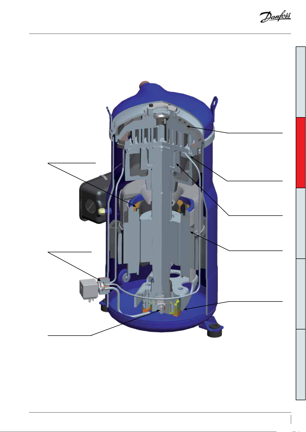
Features
High speed oil circulation
minimized by separating
oil and gas flows with a
sump oil return tube
GENERAL INFORMATIONPRODUCT INFORMATIONSYSTEM DESIGNINTEGRATION INTO SYSTEMORDERING INFORMATION
Reinforced high grade cast
iron scroll set. 2 ranges for
high and low pressure ratio
A patented oil injection
system ensures optimal
efficiency at low speed by
improving scroll set sealing
Oil injection control
optimizes the oil
circulation
Gearotor oil pump
ensures low speed
bearing lubrication
Lead free polymer bearing
with excellent performance
under diverse loads and
speeds
Permanent magnet motor
with high efficiency at all
speeds
Oil strainer controls the
risk of system debris in
the oil injection circuit
5AB221086441234en-001101
Page 6
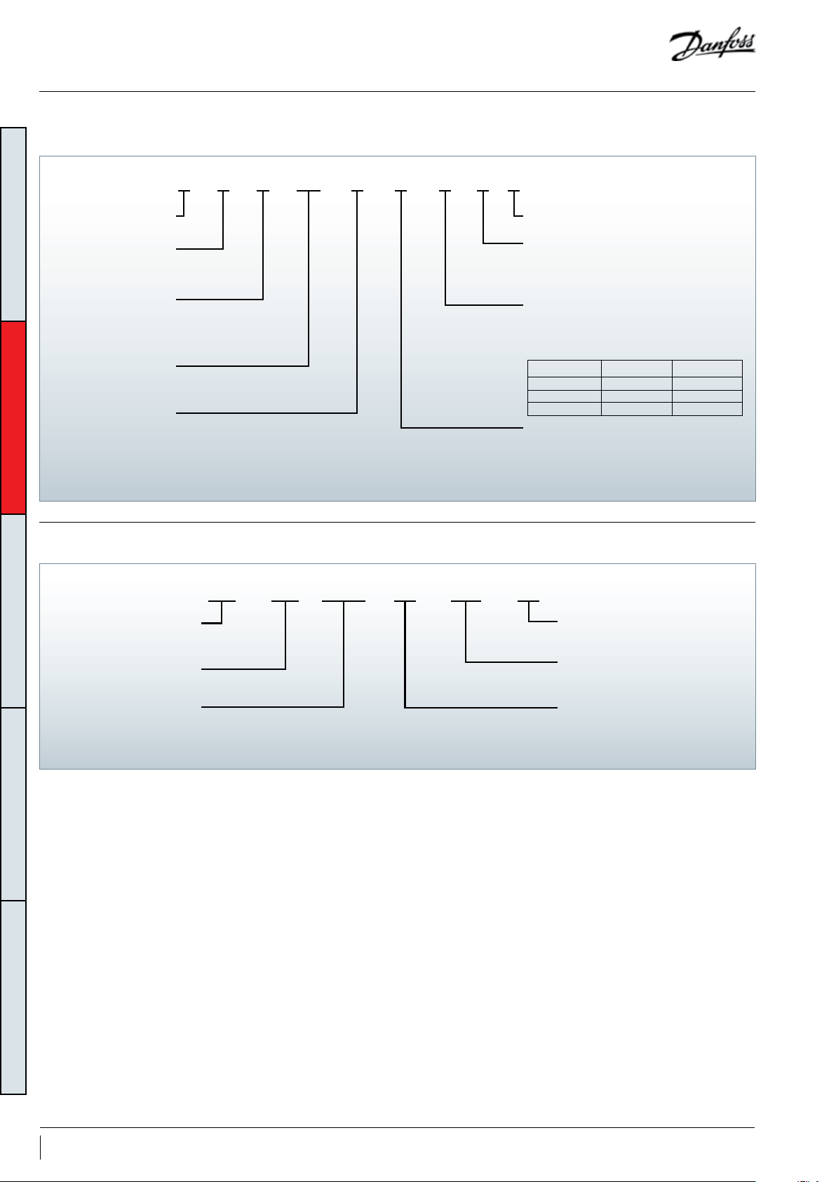
Compressor model designation
Compressor
nomenclature
ANAGA117ZHV
Variable speed
GENERAL INFORMATIONPRODUCT INFORMATIONSYSTEM DESIGNINTEGRATION INTO SYSTEMORDERING INFORMATION
Lubricant
POE lubricant, R410A
refrigerant
Swept volume
in cm³/rev
Design pressure ratio
A: high PR,
Frequency converter
nomenclature
Family
VZH scroll
B: low PR
Evolution index
Motor protection type
N: no internal motor protection
(protection by drive)
Equipement version
A: brazed connections, single version
B: brazed connections, manifold version
D: brazed connections, unified version
Oil sight glass Oil level switch
Single version Threaded None
Manifold version None Threaded
Unified version Threaded Threaded
Motor voltage code to CDS303 *
G: 380-480V/3~/50 & 60Hz
H: 525-600V/3~/50&60Hz
J: 200-240V/3~/50 & 60Hz
* main supply voltage to frequency converter
H2E20T4P15K303CDS
Dedicated compressor
drive for VZH/VSH scroll
Serie 303
High overload
output power
in kW
Note:
High overload output power: output power @160% Torque
RFI class
Enclosure protection
IP rating
Main supply voltage
T2: 200-240V/3 ph/50-60 Hz
T4: 380-480V/3 ph/50-60 Hz
T6: 525-600V/3 ph/50-60 Hz
6 AB221086441234en-001101
Page 7

Technical specifications
Compressor size
Frequency converter
variants
Compressor and
frequency converter
combinations
To have the optimum compressor selection,
select a compressor size which achieves the
peak load system cooling capacity demand at its
maximum speed.
Different frequency converter variants are
available according to:
1. Mains supply voltage
2. IP class (CDS303 drives are available in IP20 or
IP55 housings)
When the compressor size and mains voltage
have been defined in the above selection criteria,
the code number tables from the “Ordering
information and packaging” section provides the
appropriate frequency converter sizes and up
to eight corresponding code numbers for each
compressor model.
Detailed performances can be found in
datasheets and in selection programs.
3. RFI (Radio Frequency Interference) class H2/H3
or HX
4. Printed Circuit Board (PCB) coated or not
coated.
Note this compressor is equipped with
a four poles electrical motor so the applied
frequency from the inverter will be 50 Hz for
25 rps (1500 rpm) up to 200 Hz for 100 rps
(6000 rpm).
Please refer to the table below
min max
Compressor speed
Drive output frequency Hz 50 200
rps 25 100
rpm 150 0 6000
GENERAL INFORMATIONPRODUCT INFORMATIONSYSTEM DESIGNINTEGRATION INTO SYSTEMORDERING INFORMATION
7AB221086441234en-001101
Page 8

Technical specifications
Compressor
specifications
Displacement Oil charge
Compressor
model
VZH088 88.4 5.39 7.9 6 281 15.91 562 19.09 675 31.82 1125 3.3 112 3.8 12 8 55 121
VZH117 116 .9 7.13 10.52 372 21.04 744 25.25 892 42.08 1487 3.6 122 4.1 139 61 134
VZH170 170 .2 10.38 15.32 541 30.64 1083 36.76 129 9 61.27 2165 6.7 227 7.7 260 112 247
GENERAL INFORMATIONPRODUCT INFORMATIONSYSTEM DESIGNINTEGRATION INTO SYSTEMORDERING INFORMATION
Swept volume
cm³/re v cu.in/rev m³/h cu.ft/h m³/h cu.ft/h m³/ h cu.ft/h m³/ h cu.ft/h dm³ oz dm³ oz kg lbs
25 rps 50 rps 60 rps 100 rps
Single and
manifold
version
Unified
version
Net weight
Frequency converter
specifications
Oil injection control
Bearings lubrication
T2: 200 - 240 V ±10% (3-phase)
Mains supply voltage
Supply frequency 50 / 60 Hz
Output voltage 0 - 100 % of supply voltage
Inputs 6 digital (0-24V), 2 analog (0/±10V or 4-20mA, scalable)
Programmable outputs 2 digital (0-24V), 1 analog (0/4-20mA), 2 relay
Protection functions Over-current protection, low / high current handling
Compressor functions Motor protection, compressor ramp up/down control
VZH compressors are equipped with an oil
injection system that makes the compression
pockets more tight thus improving the isotropic
efficiency of the compressor as well as controls
T4: 380 - 480 V ±10% (3-phase)
T6: 525 - 600V ±10% (3-phase)
The compressors are delivered with no coils.
208V-240V / 110V-120V / 24V coils are available
as accessory (refer to “Accessories” section). The
coil must be installed for oil injection control.
the oil circulation ratio, at all running speeds.
The frequency converter via an oil injection valve
controls this system. The oil injection valve is a
normally closed valve. At low speed, the valve
Control parameters are factory preset but
accessible on the parameter list as read only
values.
is closed and the oil is injected to the scroll set
suction ports.
Optimal bearings lubrication is ensured by a
gearotor oil pump at all compressor speeds.
8 AB221086441234en-001101
Page 9
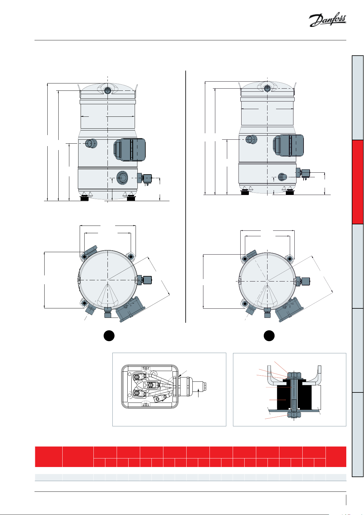
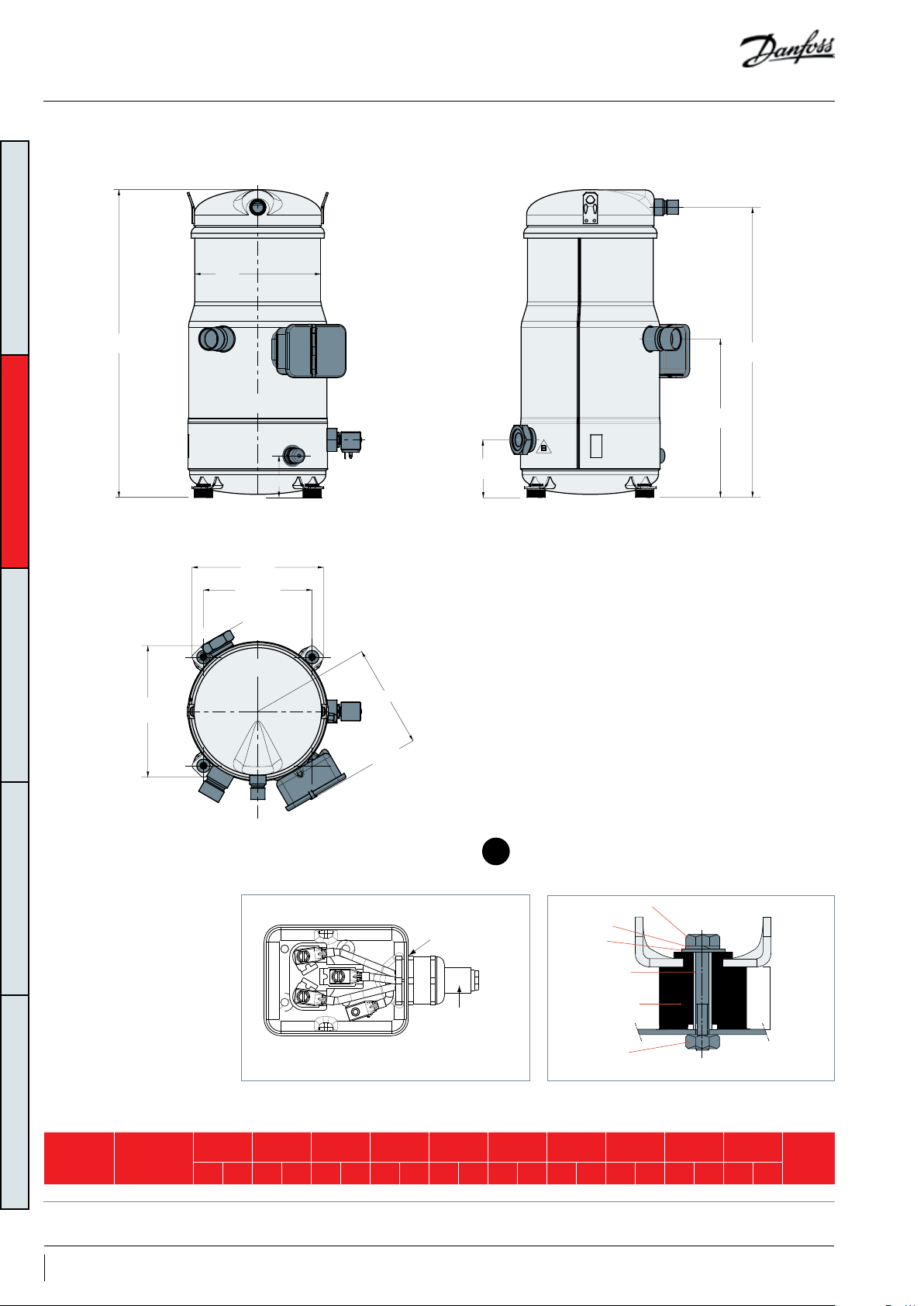
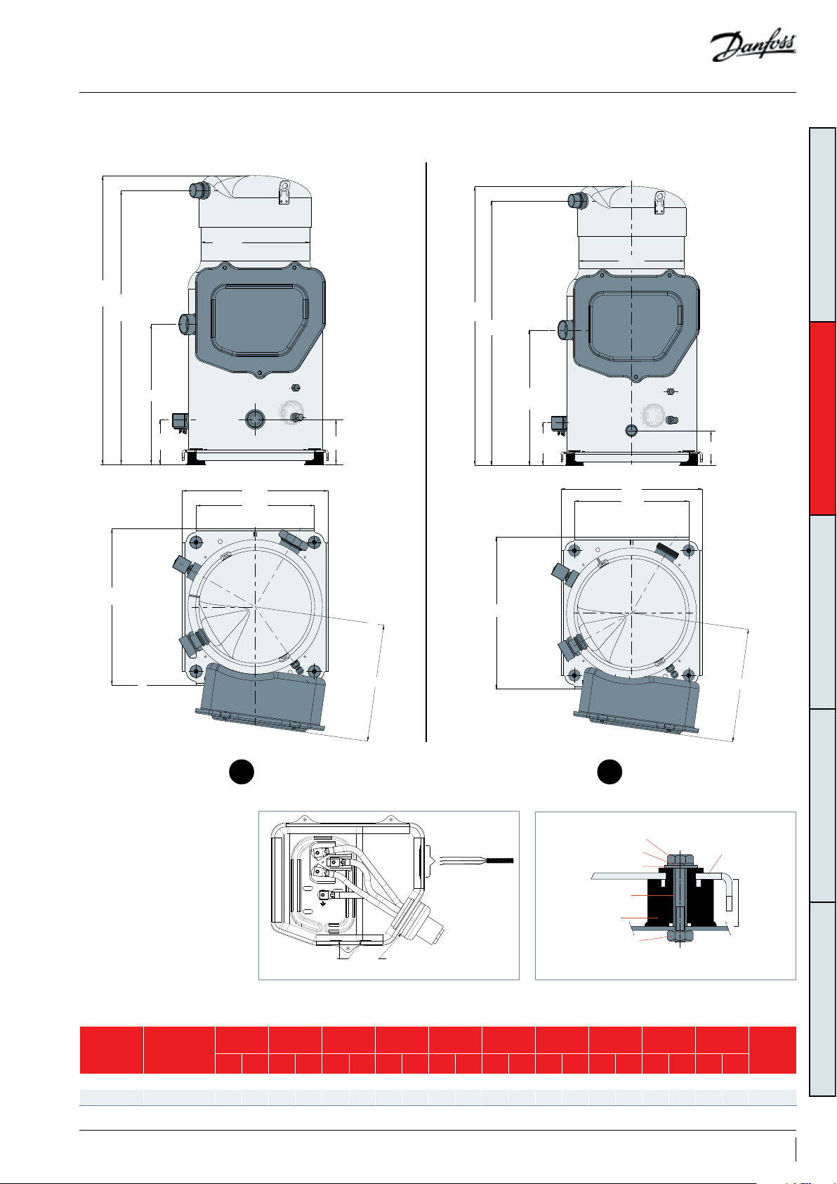
Dimensions
VZH088-G/H single
version
H3
H2
H1
ØD
L1
L3
H4
H5
VZH088-G/H manifolded version
ØD
H3
H2
H1
H4
L1
L3
GENERAL INFORMATIONPRODUCT INFORMATIONSYSTEM DESIGNINTEGRATION INTO SYSTEMORDERING INFORMATION
H5
L2
L4
L2
Ø 33 mm
(1.30 inch) hole
Power supply
GrommetElectrical box
HM 8 bolt
Lock washer
Flat washer
Steel mounting
sleeve
Rubber grommet
Nut
L4
21
15 mm
(0.59 inch)
Version
Single VZH088-G/H 220.8 8.69 234.6 9.23 451.2 17.7 6 484.8 19.08 93.8 3.69 93.8 3.69 230 9.05 230 9.05 190 .5 7. 5 18 0.7 7.11 8560025
Manifolding VZH088-G/H 220.8 8.69 234.6 9.23 451.2 17. 76 484.8 19.0 8 74. 8 2.94 93.8 3.69 230 9.05 230 9.05 19 0.5 7. 5 180.7 7. 11 8560055
Compressor
model
D H1 H2 H3 H4 H5 L1 L2 L3 L4
mm inch mm inch mm inch mm inch mm inch mm inch mm inch mm inch mm inch mm inch
Outline
drawing
number
9AB221086441234en-001101
Page 10
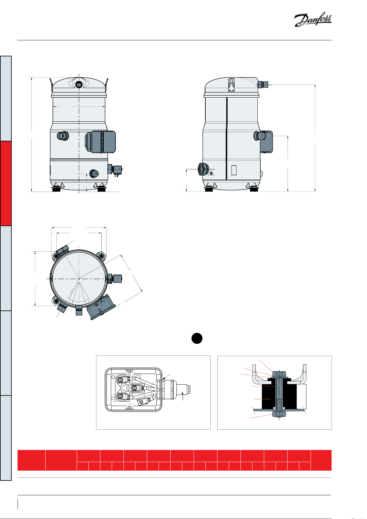
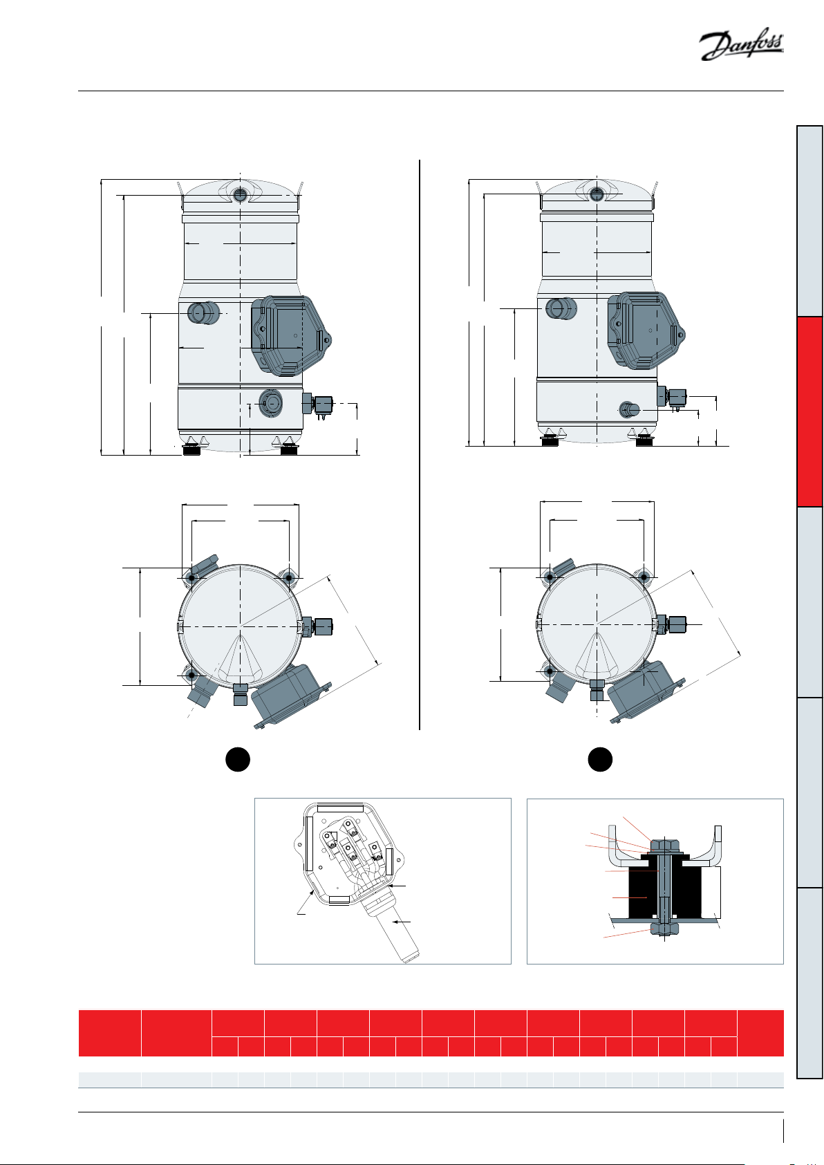
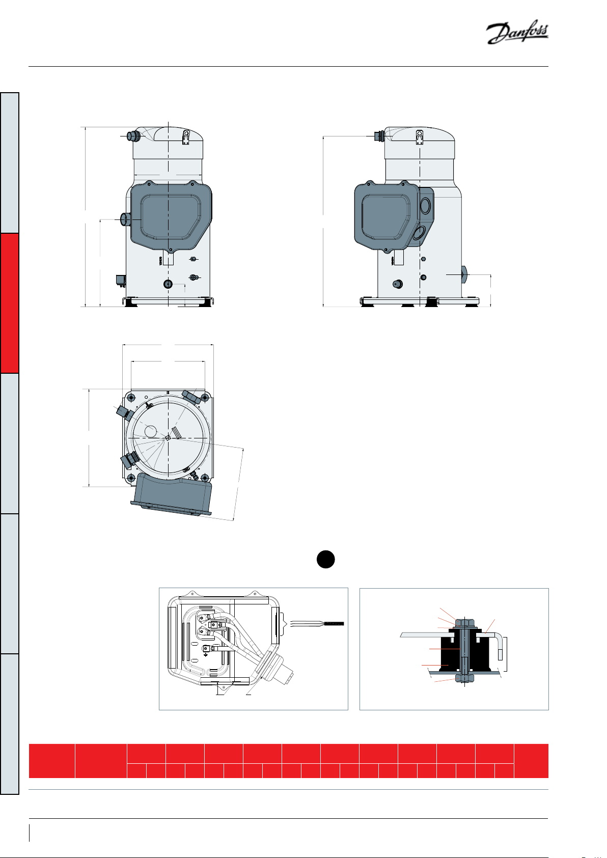
Dimensions
VZH088 -G/H unified version
ØD
GENERAL INFORMATIONPRODUCT INFORMATIONSYSTEM DESIGNINTEGRATION INTO SYSTEMORDERING INFORMATION
H3
H2
H1
L2
L1
L3
H4
L4
H5
Ø 33 mm
(1.30 inch) hole
Power supply
3
GrommetElectrical box
HM 8 bolt
Lock washer
Flat washer
Steel mounting
sleeve
Rubber grommet
15 mm
(0.59 inch)
Nut
Version
Unified VZH088-G/H 220.8 8.69 234.6 9.23 451. 2 17.76 484.8 19. 08 74 .8 2.94 93.8 3.69 230 9.05 230 9.05 19 0.5 7. 5 180 .7 7.11 8560097
Compressor
model
D H1 H2 H3 H4 H5 L1 L2 L3 L4
mm inch mm inch mm inch mm inch mm inch mm inch mm inch mm inch mm inch mm inch
10 AB221086441234en-001101
Outline
drawing
number
Page 11

Dimensions
VZH088-J single version VZH088-J manifolded version
H3
ØD
ØD
GENERAL INFORMATIONPRODUCT INFORMATIONSYSTEM DESIGNINTEGRATION INTO SYSTEMORDERING INFORMATION
H2
H1
H4
H5
H3
H2
H1
H4
H5
L1
L3
L1
L3
L4
L2
L2
L4
54
GrommetElectrical box
HM 8 bolt
Lock washer
Flat washer
Steel mounting
Ø 40.5 mm
(1.59 inch) hole
Ø 16.5 mm
(0.65 inch)
knockout
Version
Single VZH088-J 220.8 8.69 234.6 9.23 451.2 17. 76 484.8 19.0 8 93.8 3.69 93.8 3.69 230 9.05 230 9.05 19 0.5 7. 5 200.4 7.81 8560 030
Manifolding VZH088-J 220.8 8.69 234.6 9.23 451.2 17. 76 484.8 19.0 8 74. 8 2.94 93.8 3.69 230 9.05 230 9.05 19 0.5 7. 5 200.4 7. 81 8560056
Compressor
model
D H1 H2 H3 H4 H5 L1 L2 L3 L4
mm inch mm inch mm inch mm inch mm inch mm inch mm inch mm inch mm inch mm inch
Power supply
sleeve
Rubber grommet
Nut
15 mm
(0.59 inch)
Outline
drawing
number
11AB221086441234en-001101
Page 12
Dimensions
VZH088 -J unified version
ØD
GENERAL INFORMATIONPRODUCT INFORMATIONSYSTEM DESIGNINTEGRATION INTO SYSTEMORDERING INFORMATION
H3
H2
H1
H4
H5
L1
L3
L2
L4
6
GrommetElectrical box
HM 8 bolt
Lock washer
Flat washer
Steel mounting
Ø 40.5 mm
(1.59 inch) hole
Ø 16.5 mm
(0.65 inch)
knockout
Version
Unified VZH088-J 220.8 8.69 234.6 9.23 451. 2 17. 76 484.8 19.0 8 74. 8 2.94 93.8 3.69 230 9.05 230 9.05 19 0.5 7. 5 200.4 7.81 8560098
Compressor
model
D H1 H2 H3 H4 H5 L1 L2 L3 L4
mm inch mm inch mm inch mm inch mm inch mm inch mm inch mm inch mm inch mm inch
Power supply
sleeve
Rubber grommet
Nut
12 AB221086441234en-001101
15 mm
(0.59 inch)
Outline
drawing
number
Page 13
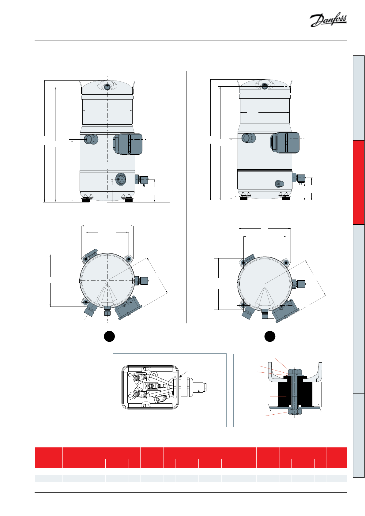
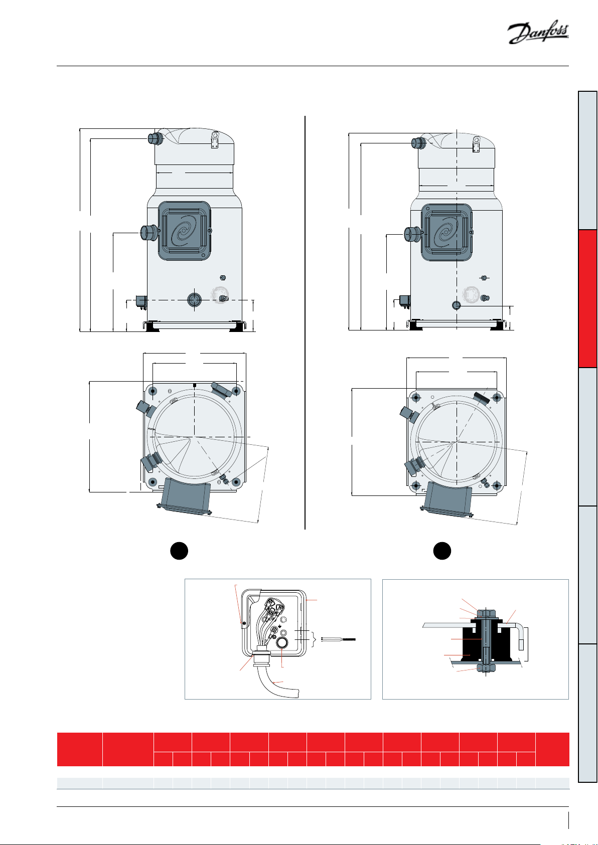
Dimensions
VZH117-G/H single version VZH117-G/H manifolded version
H3
ØD
ØD
GENERAL INFORMATIONPRODUCT INFORMATIONSYSTEM DESIGNINTEGRATION INTO SYSTEMORDERING INFORMATION
H3
H2
H1
H4
L1
L3
L2
H5
L4
H2
H1
H5
H4
L1
L3
L2
L4
87
GrommetElectrical box
HM 8 bolt
Ø 33 mm
(1.30 inch) hole
Power supply
Version
Single VZH117- G /H 220.8 8.69 276.9 10.92 50 7.9 20.02 541.6 21.34 100 3.96 100 3.96 230 9.05 230 9.05 19 0.5 7. 5 180.7 7.13 8560026
Manifolding VZH117- G/ H 220.8 8.69 276 .9 10.92 507. 9 20.02 541.6 21. 34 72 2.86 100 3.96 230 9.05 230 9.05 19 0.5 7. 5 180 .7 7.13 8560057
Compressor
model
D H1 H2 H3 H4 H5 L1 L2 L3 L4
mm inch mm inch mm inch mm inch mm inch mm inch mm inch mm inch mm inch mm inch
Lock washer
Flat washer
Steel mounting
sleeve
Rubber grommet
Nut
15 mm
(0.59 inch)
Outline
drawing
number
13AB221086441234en-001101
Page 14
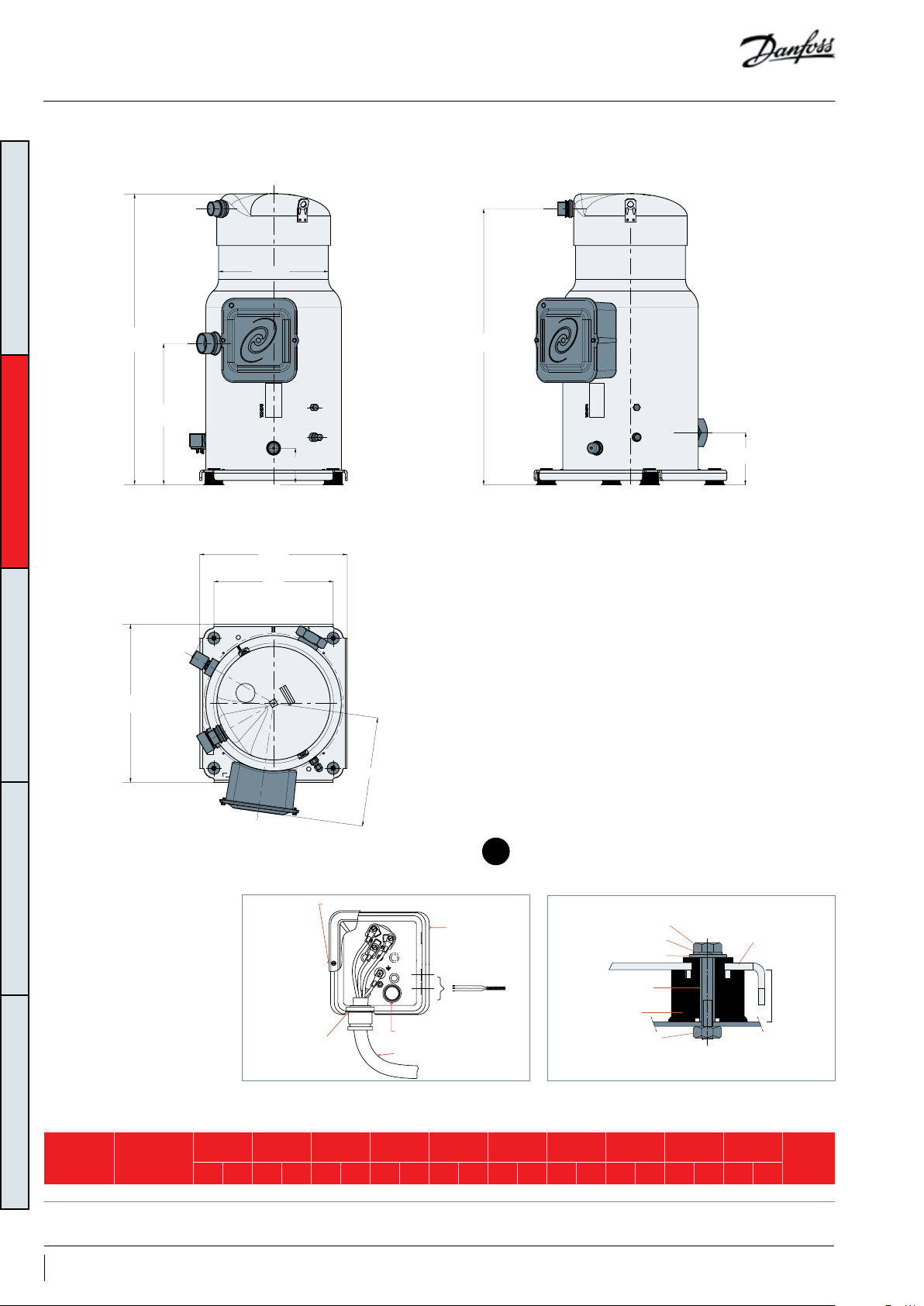
Dimensions
VZH117-G/H unified version
GENERAL INFORMATIONPRODUCT INFORMATIONSYSTEM DESIGNINTEGRATION INTO SYSTEMORDERING INFORMATION
ØD
H3
H2
H1
H4
H5
L1
L3
L4
L2
9
GrommetElectrical box
HM 8 bolt
Ø 33 mm
(1.30 inch) hole
Power supply
Version
Unified V ZH117-G/ H 220.8 8.69 276.9 10.92 507. 9 20.02 5 41.6 21.3 4 72 2.86 10 0 3.96 230 9.05 230 9.05 190 .5 7. 5 18 0.7 7.13 8560099
Compressor
model
D H1 H2 H3 H4 H5 L1 L2 L3 L4
mm inch mm inch mm inch mm inch mm inch mm inch mm inch mm inch mm inch mm inch
Lock washer
Flat washer
Steel mounting
sleeve
Rubber grommet
Nut
14 AB221086441234en-001101
15 mm
(0.59 inch)
Outline
drawing
number
Page 15
Dimensions
VZH117-J single version VZH117-J manifolded version
H3
H2
ØD
ØD
GENERAL INFORMATIONPRODUCT INFORMATIONSYSTEM DESIGNINTEGRATION INTO SYSTEMORDERING INFORMATION
H3
H2
Ø243
H1
H1
H4
L1
L3
L2
H5
L1
L3
L4
L2
H4
H5
L4
1110
GrommetElectrical box
HM 8 bolt
Lock washer
Flat washer
Steel mounting
Ø 40.5 mm
(1.59 inch) hole
Ø 16.5 mm
(0.65 inch)
knockout
Version
Single VZH117-J 220.8 8.69 276.9 10.92 507.9 20.02 541. 6 21.34 100 3.96 100 3.96 230 9.05 230 9.05 19 0.5 7. 5 200.4 7. 87 856 0031
Manifolding VZ H117-J 220.8 8.69 276.9 10.92 5 07.9 20.02 541.6 21.34 72 2.86 100 3.96 230 9.05 230 9.05 190 .5 7. 5 200.4 7. 87 8560058
Compressor
model
D H1 H2 H3 H4 H5 L1 L2 L3 L4
mm inch mm inch mm inch mm inch mm inch mm inch mm inch mm inch mm inch mm inch
Power supply
sleeve
Rubber grommet
Nut
15 mm
(0.59 inch)
Outline
drawing
number
15AB221086441234en-001101
Page 16

Dimensions
VZH117-J unified version
GENERAL INFORMATIONPRODUCT INFORMATIONSYSTEM DESIGNINTEGRATION INTO SYSTEMORDERING INFORMATION
H3
ØD
H2
H1
H4
H5
L1
L3
L4
L2
12
GrommetElectrical box
HM 8 bolt
Lock washer
Flat washer
Steel mounting
Ø 40.5 mm
(1.59 inch) hole
Ø 16.5 mm
(0.65 inch)
knockout
Version
Unified V ZH 117-J 220.8 8.69 276.9 10 .92 507.9 20.02 541. 6 21.34 72 2.86 10 0 3.96 230 9.05 230 9.05 190 .5 7. 5 200.4 7.8 7 856 0100
Compressor
model
D H1 H2 H3 H4 H5 L1 L2 L3 L4
mm inch mm inch mm inch mm inch mm inch mm inch mm inch mm inch mm inch mm inch
Power supply
sleeve
Rubber grommet
Nut
16 AB221086441234en-001101
15 mm
(0.59 inch)
Outline
drawing
number
Page 17
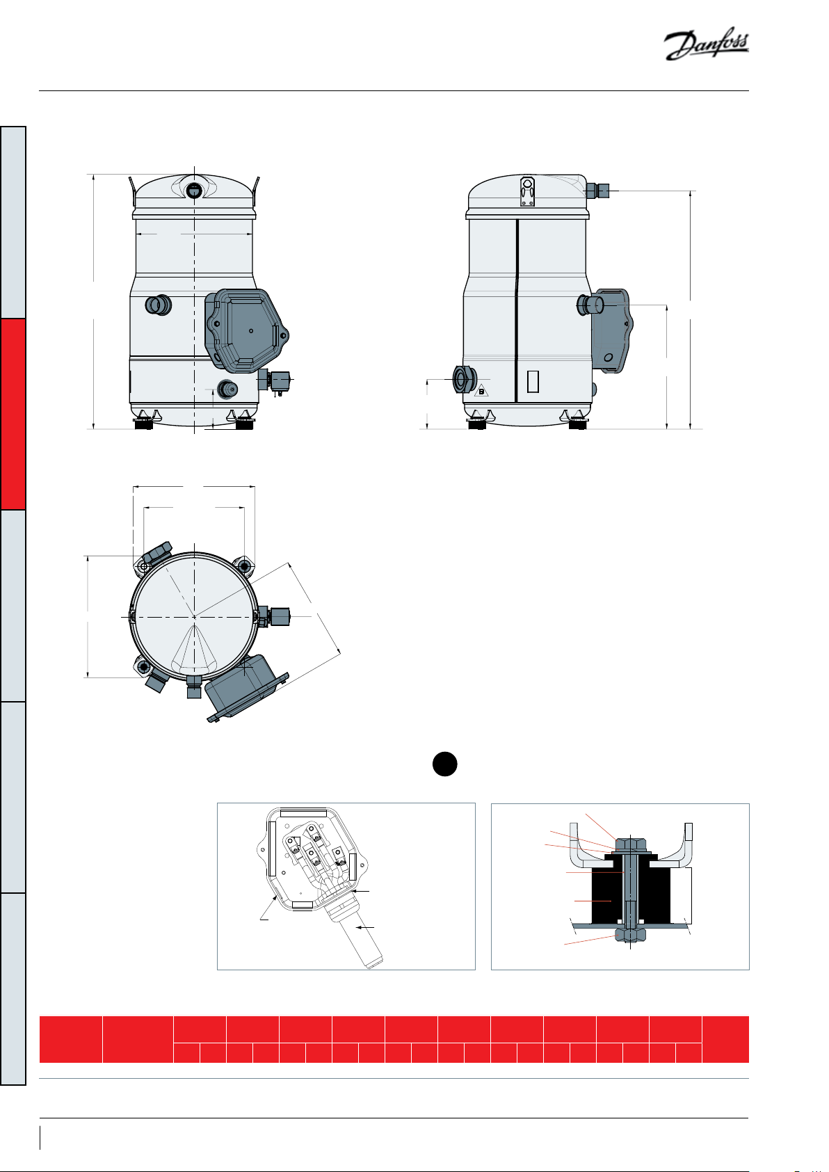
Dimensions
Cover holding screw (x2) - Torque: 2.2 Nm
VZH170-G/H single version VZH170-G/H manifolded version
ØD
ØD
H3
H2
H3
H2
GENERAL INFORMATIONPRODUCT INFORMATIONSYSTEM DESIGNINTEGRATION INTO SYSTEMORDERING INFORMATION
H1
H5
L1
L3
L2
H4
L2
L4
H1
H5
L1
L3
H4
L4
1413
GrommetElectrical box
Terminal box
Sump heater
Steel mounting sleeve
Rubber grommet
Ø 40.5 mm
(1.59 inch) hole
Ø 50.5 mm
Faston 1/4" tabs
Power supply
(1.99 inch) knockout
Version
Compressor
model
D H1 H2 H3 H4 H5 L1 L2 L3 L4
mm inch mm inch mm inch mm inch mm inch mm inch mm inch mm inch mm inch mm inch
Single VZ H170 -G/H 257 10.12 329 12.97 644.5 25.39 686.5 2 7.04 104.1 4.10 10 4.1 4.10 345 13.58 371 14.61 279.4 11 257 10 .12 8 5511 86
Manifolding VZH170- G/ H 257 10.12 329 12 .97 644.5 25.39 686.5 2 7.0 4 83.6 3. 3 10 4.1 4.10 345 13.58 371 14.61 279.4 11 257 10 .12 8 5511 87
HM 8 bolt
Lock washer
Flat washer
Nut
Compressor
base plate
28 mm
(1.10 inch)
drawing
Outline
number
17AB221086441234en-001101
Page 18
Dimensions
Cover holding screw (x2) - Torque: 2.2 Nm
VZH170-G/H unified version
GENERAL INFORMATIONPRODUCT INFORMATIONSYSTEM DESIGNINTEGRATION INTO SYSTEMORDERING INFORMATION
H3
H1
ØD
H2
H4
H5
L1
L3
L2
L4
15
GrommetElectrical box
Ø 40.5 mm
(1.59 inch) hole
Ø 50.5 mm
(1.99 inch) knockout
Version
Unified VZH170 -G/H 257 10.12 329 12.97 644.5 25. 39 686.5 2 7.0 4 83.6 3.3 120.5 4. 74 345 13. 58 371 14.61 279.4 11 257 10 .12 8560095
Compressor
model
D H1 H2 H3 H4 H5 L1 L2 L3 L4
mm inch mm inch mm inch mm inch mm inch mm inch mm inch mm inch mm inch mm inch
Faston 1/4" tabs
Power supply
Terminal box
Sump heater
Steel mounting sleeve
Rubber grommet
HM 8 bolt
Lock washer
Flat washer
Nut
18 AB221086441234en-001101
Compressor
base plate
28 mm
(1.10 inch)
Outline
drawing
number
Page 19
Dimensions
VZH170-J single version VZH170-J manifolded version
ØD
ØD
H3
H2
H1
H5
L1
L3
L2
H4
L4
H3
H2
H1
H5
L1
L3
L2
H4
L4
GENERAL INFORMATIONPRODUCT INFORMATIONSYSTEM DESIGNINTEGRATION INTO SYSTEMORDERING INFORMATION
1716
GrommetElectrical box
HM 8 bolt
Lock washer
Sump heater
Flat washer
Steel mounting sleeve
Rubber grommet
Nut
Ø 50.5 mm (1.99 inch) hole
Ø 63.5 mm (2.50 inch) knockout
Version
Compressor
model
Ø 22.5 mm
(0.89 inch) knockout
D H1 H2 H3 H4 H5 L1 L2 L3 L4
mm inch mm inch mm inch mm inch mm inch mm inch mm inch mm inch mm inch mm inch
Single V ZH170 -J 257 10 .12 329 12 .97 644.5 25.39 686.5 2 7.0 4 104.1 4.10 10 4.1 4.10 345 13.58 371 14.61 279.4 11 277 10 .90 85 51174
Manifolding VZH170 -J 257 10.12 329 12. 97 644.5 25. 39 686.5 2 7.0 4 83.6 3. 3 104.1 4 .10 345 13.58 371 14.61 279.4 11 277 10.9 0 8 5511 88
Compressor
base plate
28 mm
(1.10 inch)
Outline
drawing
number
19AB221086441234en-001101
Page 20
Dimensions
VZH170-J unified version
ØD
GENERAL INFORMATIONPRODUCT INFORMATIONSYSTEM DESIGNINTEGRATION INTO SYSTEMORDERING INFORMATION
H3
H1
H4
L1
L3
L2
L4
H2
H5
18
GrommetElectrical box
HM 8 bolt
Lock washer
Sump heater
Steel mounting sleeve
Rubber grommet
Ø 22.5 mm
(0.89 inch) knockout
Version
Compressor
model
D H1 H2 H3 H4 H5 L1 L2 L3 L4
mm inch mm inch mm inch mm inch mm inch mm inch mm inch mm inch mm inch mm inch
Unified VZH170 -J 257 10 .12 329 12 .97 644.5 25. 39 686.5 2 7.0 4 83.6 3. 3 12 0.5 4 .74 345 13 .58 371 14. 61 279.4 11 277 10 .90 8560096
Ø 50.5 mm (1.99 inch) hole
Ø 63.5 mm (2.50 inch) knockout
Flat washer
Nut
20 AB221086441234en-001101
Compressor
base plate
28 mm
(1.10 inch)
Outline
drawing
number
Page 21
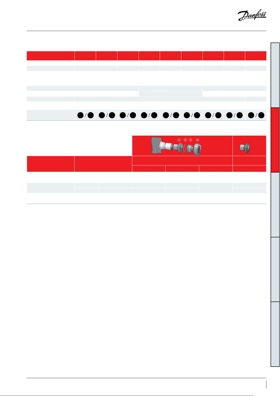
Dimensions
Connection Details
VZH088
Single
Suction connection 1"1/8 1"1/8 1"1/8 1"3/8 1"3/8 1"3/8 1"5/8 1"5/8 1"5/8
Discharge connection 7/8 " 7/8" 7/8 " 7/8" 7/8 " 7/8" 1"1/8 1"1/8 1"1/8
Oil sight glass
Oil level sensor None Threaded M20x1.5 None Threaded M20x1.5 None Threaded M20x1.5
Oil equalization connection Rotolock 1"3/4 Rotolock 1"3/4 Rotolock 2"1/4
Oil drain connection Female 1/4" Flare incorporating a Schrader valve
Low pressure gauge port
(Schrader)
Outline
Compressor models Brazed connection size
VZH088
VZH117
VZH170
Threaded
(1"1/8 – 18
UNF)
1 2 3 7 8 9 13 14 154 5 6 10 11 12 16 17 18
Suction 1"1/8 1"3/4 1"1/8
Discharge 7/8" 1"1/4 7/8" 120Z03 67
Suction 1"3/8 1"3/4 1"3/8
Discharge 7/8" 1"1/4 7/8" 120Z03 67
Suction 1"5/8 2 "1/4 1"5/8
Discharge 1"1/8 1"3/4 1"1/8 120Z03 64
VZH088
Manifolding
None
VZH088
Unified
on oil
equalization
port
Male 1/4" Flare incorporating a Schrader valve
VZH117
Single
Threaded
(1"1/8 – 18
UNF)
Rotolock Solder sleeve ODF Code Number Code Number
VZH117
Manifolding
None
Rotolock adaptor set
(adaptor, gasket, sleeve, nut)
VZH117
Unified
on oil
equalization
port
VZH170
Single
Threaded
(1"1/8 – 18
UNF)
120Z0125
120Z0405
7765028
VZH170
Manifolding
None
Rotolock adaptor
( adaptor only)
VZH170
Unified
on oil
equalization
port
120Z03 64
120Z0431
120Z0432
GENERAL INFORMATIONPRODUCT INFORMATIONSYSTEM DESIGNINTEGRATION INTO SYSTEMORDERING INFORMATION
VZH compressors are all delivered with suction
and discharge brazed connections only. They are
copper-plated steel connections.
Rotolock adaptors are available, refer to the
information above.
21AB221086441234en-001101
Page 22
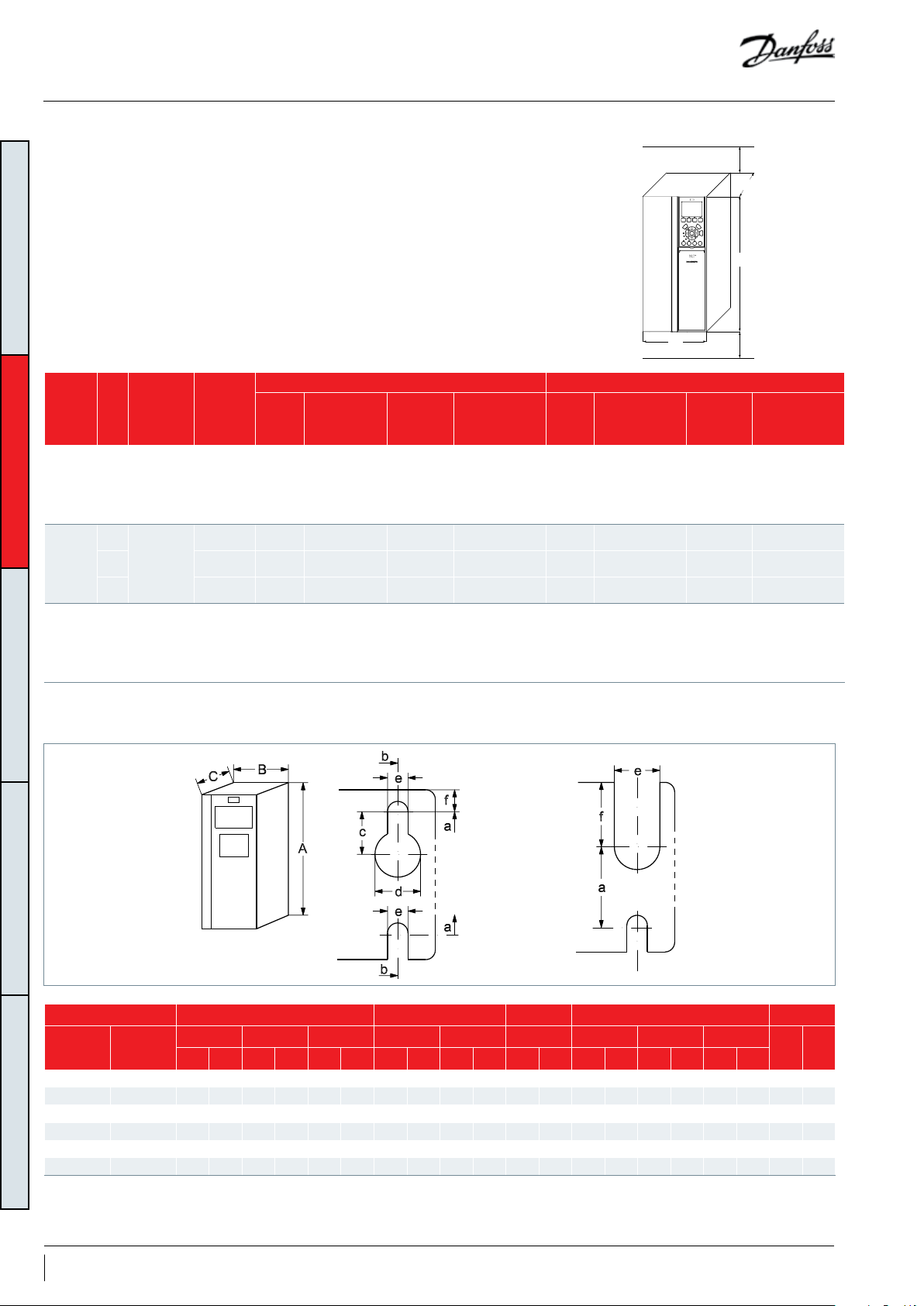
Dimensions
CDS303 Frequency
converter
GENERAL INFORMATIONPRODUCT INFORMATIONSYSTEM DESIGNINTEGRATION INTO SYSTEMORDERING INFORMATION
Drive
Drive
supply
power
voltage
200-240/3/
50-60
380-480/3/
50-60
525- 600/3/
50-60
kW
15
T2:
18. 5 V ZH117 C3
22 VZ H170 C3
15
T4:
18. 5 V ZH117 B4
22 VZ H170 B4
18
T6:
30 V ZH117 B4
30 VZ H170 B4
Compressor
voltage code
J
G
H
Frequency converter dimensions depend
on supply voltage, IP rating and power. The
table below gives an overview of the overall
dimensions and different drive enclosures (B1 B4). Details for each drive enclosure are on the
following pages.
IP20 IP55
Compressor
model
VZH088 B4
VZH088 B3
VZH088 B4
Drive
enclosure
Overall drive size
[H x W x L]
mm
(inch)
595x230x242
(23.43x 9.09x9. 53)
630x308x333
(24 .8x 12.13 x13.15)
630x308x333
(24 .8x 12.13 x13.15)
420x165x 249
(16.5x6. 5x9.76)
595x230x242
(23.42x9.09x 9.53)
595x230x242
(23.42x9.09x 9.53)
595x230x242
(23.42x9.09x 9.53)
595x230x242
(23.42x9.09x 9.53)
595x230x242
(23.42x9.09x 9.53)
Clearance
above/below
mm
(inch)
200
200
200
200
200
200
200
200
200
W
bracket supplied
2
(mm
)
enclosure
2pcs, ø24-28k28b
(8)
1pcs, ø32-36 k36b
1pcs, ø32-36 k36b
(8)
1pcs, ø36-40 k40b
1pcs, ø32-36 k36b
(8)
1pcs, ø36-40 k40b
(8)
(8)
(8)
(8)
(8)
(8)
3pcs, Ø13-22 B1
2pcs, ø24-28 k28b B2
2pcs, ø24-28 k28b B2
2pcs, ø24-28 k28b - - - -
2pcs, ø24-28 k28b - - - -
2pcs, ø24-28 k28b - - - -
Drive
C1
C1
C1
Overall drive size
[H x W x L]
mm
(inch)
680x308x310
(26.78x12 .13x12.20 )
680x308x310
(26.78x12 .13x12.20 )
680x308x310
(26.78x12 .13x12.20 )
480x242x260
(18.9x9. 45x10.24)
650x242x260
(25.6x 9.53x10.24)
650x242x260
(25.6x 9.53x10.24)
Clearance
above/below
mm
(inch)
200
(8)
200
(8)
200
(8)
100
(4)
200
(8)
200
(8)
Min 100/200
Clearance above for cooling
L
H
Min 100/200
Clearance above for cooling
bracket supplied
(mm2)
1pcs, ø32-36 k36b
1pcs, ø36-40 k40b
1pcs, ø32-36 k36b
1pcs, ø36-40 k40b
1pcs, ø32-36 k36b
1pcs, ø36-40 k40b
3pcs, ø3-32
3pcs, ø3-32
3pcs, ø14-40
For customers who needs other size brackets, please refer to accessories for ordering.
Enclosure Height Width Depth Mounting hole Max. Weight
Frame IP Class
B1 IP55 480 18.90 - - 454 17. 87 242 9. 53 210 8. 27 260 10. 24 19 0.75 9 0.35 9 0.35 23 51
B2 IP55 650 25. 59 - - 624 24.57 242 9.53 210 8.27 260 10.24 19 0.75 9 0. 35 9 0. 35 27 60
B3 IP20 399 15.71 420 16. 54 380 14.96 165 6.5 140 5 .51 249 9.8 12 0.47 6.8 0.27 7.9 0.31 12 26
B4 IP20 520 20.47 595 23.43 495 19 .49 230 9.06 200 7. 87 242 9. 53 - - 8.5 0. 33 15 0.59 23 51
C1 IP55 680 26.77 - - 648 2 5.51 308 12 .13 272 10.71 310 12. 20 19 0.75 9 0.35 9.8 0.39 45 99
C3 IP20 550 21.6 5 630 24.80 521 20.51 308 12 .13 270 10.63 333 13.11 - - 8.5 0.33 17 0.67 50 110
1)
A
Including decoupling plate.
The dimensions are only for the physical units, but when installing in an application it is necessary to add space for free air passage both above and below the units. The amount
of space for free air passage is listed in “frequency converter dimensions - Clearance above/below (mm/inch)”.
A A
mm inch mm inch mm inch mm inch mm inch mm inch mm inch mm inch mm inch
1)
a B b C d e f
kg lb
22 AB221086441234en-001101
Page 23

Electrical data, connections and wiring
Supply voltage
Compressor electrical
specifications
Because VZH compressors are powered by a
frequency converter, the mains frequency, 50 or
60 Hz, is no longer an issue. Only the mains
voltage is to be taken into account. With 3 motor
voltage codes, the most common mains voltages
There is no modification for cooling capacity and
power input.
Since data published for code H is based on 575V
frequency converter supply, thus there will be no
coefficients modification applied for H code.
and frequencies are covered. Never connect the
VZH compressor directly to the mains power
supply in case of motor burnt.
VZH all published data and polynomials are
Voltage code Mains voltage range of drive
J 200-240V / 3ph / 50Hz & 60Hz (±10%)
G 380-480V / 3ph / 50Hz & 60Hz (±10%)
based on 208V frequency converter power supply
for code J and 400V for code G. When having
H 525-600V /3ph / 50Hz & 60Hz (±10%)
a supply of 230V, 380V or 460V the following
coefficients must be applied:
I
= 0.87* I
460
I
= 1.05* I
380
I
= 0.90* I
230
RW: Winding resistance per winding (in CDS303 parameter list)
RLA: Rated load current
MMT: Maximum must trip current
Note that parameter 1-30 in the frequency converter settings reflects the winding resistance per winding. This is not the same value
as measured at the motor terminals.
400
400
208
200 - 240 Volt
380 - 480 Volt
525 - 600 Volt
Compressor
VZH088-J 0.03 74. 8 93.5
VZH117-J 0.02 88.0 110 .0
VZH170-J 0.01 115.0 143.8
VZH088-G 0.10 37. 5 46.9
VZH117- G 0.08 44.0 55.0
VZH170- G 0.05 61.0 76.3
VZH088-H 0.10 37. 5 46.9
VZH117- H 0.08 44.0 55.0
VZH170- H 0.05 61.0 76.3
RW RLA MMT
(Ohm) (A) (A)
GENERAL INFORMATIONPRODUCT INFORMATIONSYSTEM DESIGNINTEGRATION INTO SYSTEMORDERING INFORMATION
RLA (Rated Load Amp)
MMT (Maximum Must
Trip current)
Wiring connections
Rated Load Amp value is the current value at
maximum load, in the operating envelope, and at
maximum speed and rated drive input voltage.
The Maximum Must Trip current is defined
for compressors not equipped with their
own motor protection. This MMT value is the
maximum at which the compressor can be
operated in transient conditions and out of
the operating envelope. The tripping current
of external overcurrent protection, in this case
Electrical power is connected to the compressor
terminals by Ø 4.8 mm (3/16") screws. The
maximum thightening torque is 3 Nm. Use a 1/4"
ring terminal on the power leads.
RLA is the measured value at the compressor
terminals (after the drive).
preprogrammed in the drive, never exceeds the
MMT value.
For VZH compressors, according to
ULrequirements, MMT value is 125% of RLA. This
value is printed on the compressor nameplate.
Cable gland or similar protection
component must be used on electrical box’s
knockouts to against accidental contact with
electrical parts inside.
23AB221086441234en-001101
Page 24
Electrical data, connections and wiring
Cover holding screw (x2) - Torque: 2.2 Nm
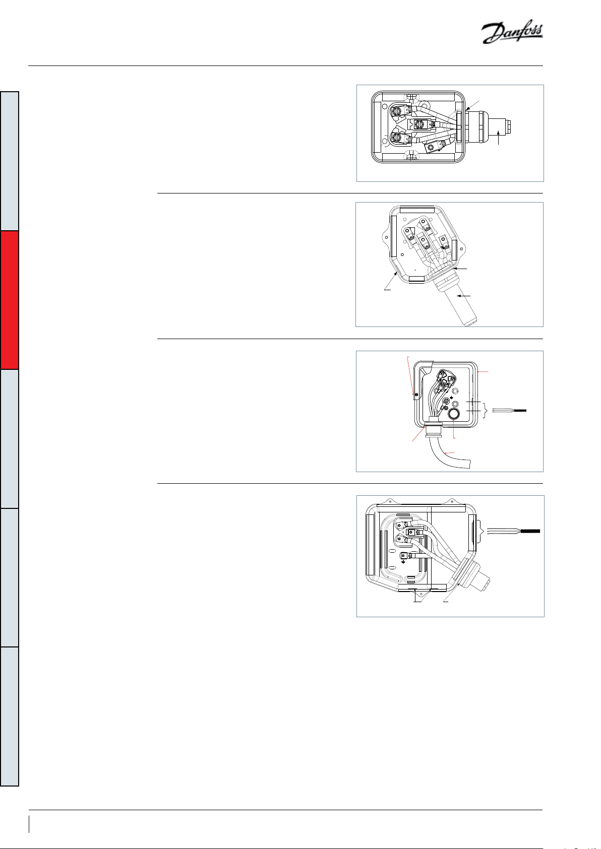
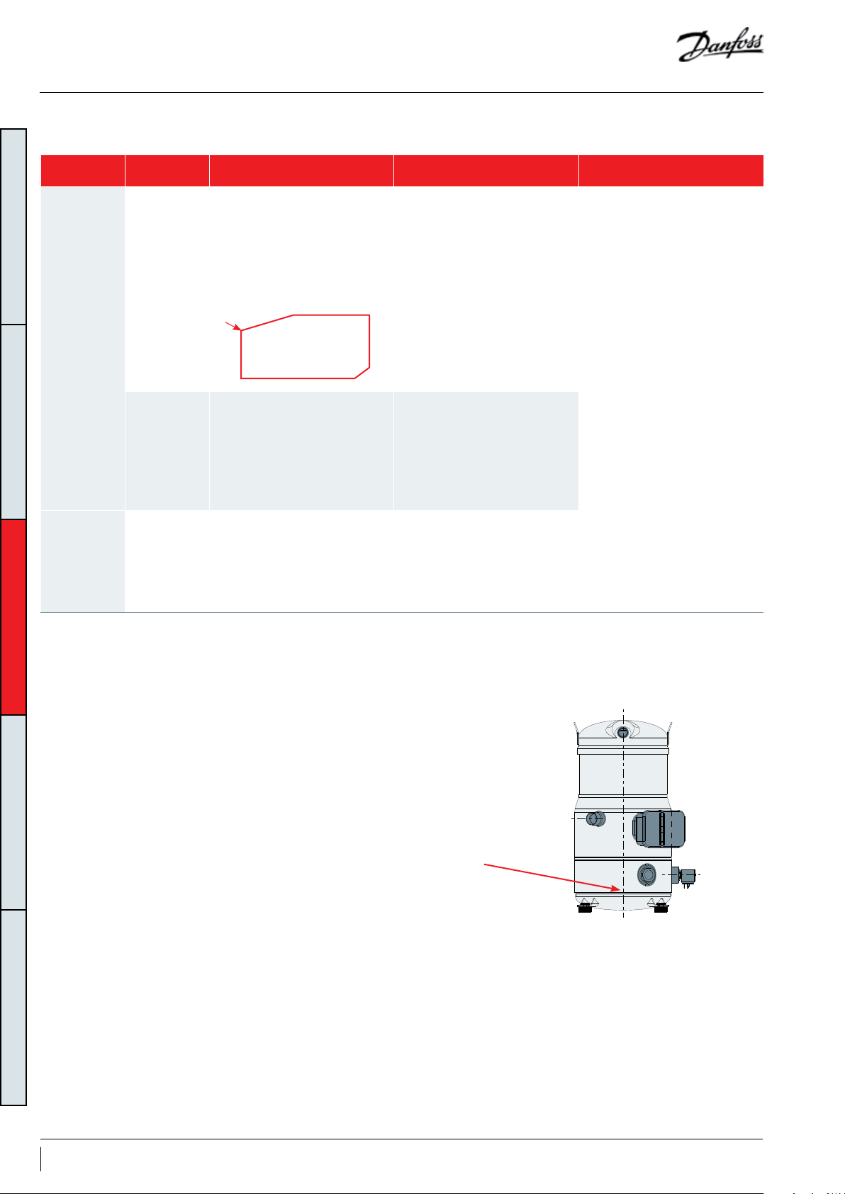
VZH0 88/117- G/H The terminal box is provided with a φ 33mm
(φ1.3 inch) hole (ISO32) for power supply.
VZH0 88/117-J
GENERAL INFORMATIONPRODUCT INFORMATIONSYSTEM DESIGNINTEGRATION INTO SYSTEMORDERING INFORMATION
VZH170-G/H
The terminal box is provided with a φ 40.5mm
(φ1.59 inch) hole (ISO40) for power supply and a
φ 16.5mm (φ0.65 inch) knockout (ISO16) .
φ 40.5mm (φ 1.59inch) (ISO 40) hole with possible
φ 50.5mm (φ 1.98inch)(ISO50) knockout for
power supply
Ø 16.5 mm
(0.65 inch)
knockout
Ø 33 mm
(1.30 inch) hole
Power supply
Ø 40.5 mm
(1.59 inch) hole
Power supply
Terminal box
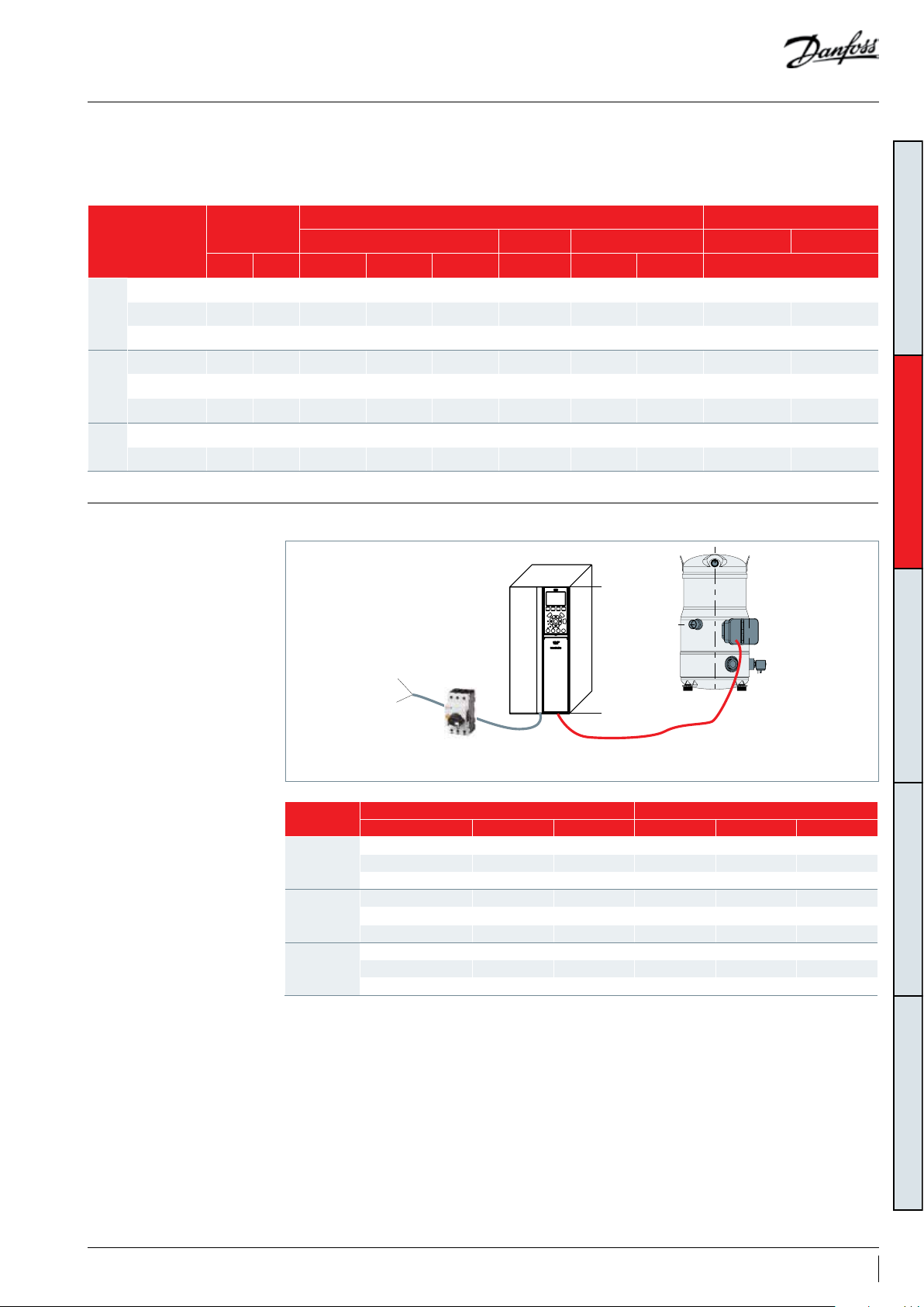
VZH170-J
φ 50.5mm (φ 1.98inch) (ISO 50 & UL1”1/2
conduit) hole with possible φ 63.5mm (φ 2.5inch)
(ISO63 and UL 2”conduit) knockout for power
supply.
• 2 x φ 22.5mm (φ 0.89inch) (PG16 and UL .”
conduit) knockouts.
Ø 40.5 mm
(1.59 inch) hole
Ø 50.5 mm
(1.99 inch) knockout
Ø 22.5 mm
(0.89 inch) knockout
Sump heater
Faston 1/4" tabs
Power supply
Sump heater
Ø 50.5 mm (1.99 inch) hole
Ø 63.5 mm (2.50 inch) knockout
24 AB221086441234en-001101
Page 25
Electrical data, connections and wiring
Fuses / circuit breakers
Danfoss recommends using the fuses/circuit
breakers listed below to protect service
personnel and property in case of component
EN 50178
Frequency converter
CDS-15kW 125 A gG KTN -R125 JKS-150 JJN-125 2028220-125 K LN- R125 A2K-125R NZMB1-A100 NZMB2-A200
CDS-18.5 kW 125 A gG K TN-R12 5 JKS -150 JJN -125 2028220-125 KLN -R125 A 2K-125R NZMB2-A200 NZMB2-A200
200-240 V
CDS -22 kW 16 0 A gG F WX-150 - - 2028220-150 L25S-15 0 A25X-150 NZMB2-A200 NZMB2-A200
CDS-15 kW 63 A gG KTS-R50 JKS-50 JJS-50 5014006-050 KLS-R50 A6K-50R PKZM4-50 PKZM4-63
CDS-18.5 Kw 63 A gG KTS-R60 JKS-60 JJS-60 5014006 -063 KLS-R60 A6K-60R N ZMB1-A100 N ZMB1-A100
380-480 V
CDS -22 kW 80 A gG KTS-R80 JKS-80 JJS-80 2028220-100 KLS-R80 A6K-80R NZMB1-A100 NZM B1-A100
CDS-18.5 kW 40A gG KTS-R50 JKS-50 JJS-50 5014006-050 KLS-R50 A6K-50R NZMB1-A100 -
CDS-30 kW 63A gG KTS-R80 JKS-80 IJS-80 5014006- 080 KLS-R80 A6K-80R NZMB1-A100 -
525-600V
compliant fuses
Size Type Type RK1 Type J Type T Type RK1 Type RK1 Type RK1 Moeller type
Bussmann SIBA Little fuse IP20 IP55
UL Compliant fuses Recommended circuit breaker
break-down in the frequency converter. For
circuit breakers, Moeller types have been tested
and are recommended.
Wire sizes Below table lists maximum wiring sizes for the motor compressor power supply cables.
GENERAL INFORMATIONPRODUCT INFORMATIONSYSTEM DESIGNINTEGRATION INTO SYSTEMORDERING INFORMATION
from network
to drive
I
Power input
Circuit breaker
From network to frequency converter From frequency converter to compressor
Typ e mm² AWG Type mm² AWG
CDS-15kW 25 4 VZH088-J 25 4
200 - 240 V
380 - 400 V
525 - 600 V
Note: The wire size here is the guidelines is the maximum wire size connectors can accept but not the actual needed cable. The needed cable size should be specified by the OEM depending on the unit design, ambient temperature, the wire material, current, etc...
CDS-18.5 kW 35 2 V ZH117-J 35 2
CDS -22 kW 50 1 V ZH170-J 50 1
CDS-15 kW 6 10 VZH088-G 6 10
CDS-18.5 Kw 10 8 V ZH117- G 10 8
CDS -22 kW 16 6 VZH17 0- G 16 6
CDS-18.5 kW (IP20) 10 8 VZH088-H 6 10
CDS-30kW (IP20) 25 4 VZH117- H 10 8
CDS-30kW (IP20) 25 4 VZH170H 16 6
from drive to
to compressor
25AB221086441234en-001101
Page 26

Electrical data, connections and wiring
Soft-start control
Phase sequence and reverse rotation protection
GENERAL INFORMATIONPRODUCT INFORMATIONSYSTEM DESIGNINTEGRATION INTO SYSTEMORDERING INFORMATION
The CDS303 frequency converter generates by
design a compressor soft start with an default
initial ramp up of 2700rpm/s.
Current inrush will not exceed the frequency
converter maximum current.
The compressor will only operate properly
in a single direction. If electrical connections
are done correctly between the drive and the
compressor terminals (compressor T1/T2/T3 and
drive terminals U, V & W matching), the drive will
provide correct phase supply to the compressor,
and reverse rotation will be not possible:
• CDS terminal U (96) to VZH terminal T1
• CDS terminal V (97) to VZH terminal T2
• CDS terminal W (98) to VZH terminal T3
If compressor T1/T2/T3 and drive U, V & W
terminals are not matching, the compressor
can operate in a reverse rotation. This results in
excessive noise, no pressure differential between
Basically seen from the mains, the inrush peak
reach a level which is only a few percent more
than the rated nominal current.
suction and discharge, and suction line warming
rather than immediate cooling. The compressor
can be rapidly damaged in these conditions.
If reverse rotation symptoms occur, shut the
compressor down and connect the phases to
their proper terminals.
Mains connection to the CDS frequency
converter order has no influence on the output
phase sequence which is managed by the
frequency converter.
26 AB221086441234en-001101
Page 27

Electrical data, connections and wiring
IP rating
Motor protection
The compressor terminal box IP rating according
to CEI529 is IP54 when correctly sized IP54 rated
cable glands are used.
Element Numerals or letters Meaning for the protection of equipment
Against ingress of solid foreign objects
0
First characteristic
numeral
Second
characteristic
numeral
1
2
3
4
5
6
0
1
2
3
4
5
6
7
8
VZH scroll compressors are not equipped with
an internal motor protector. Motor protection
is provided by the variable speed drive. All
parameters are factory preset in order to
guaranty locked rotor or overload current
(non protected)
≥ 50 mm diameter
≥ 12.6 mm diameter
≥ 2.5 mm diameter
≥ 1.0 mm diameter
dust protected
dust tight
Agains ingress of water with harmful effects
(non protected
vertically dripping
dripping (15° tilted)
spaying
splashing
jetting
powerful jetting
temporary immersion
continuous immersion
When a warning situation is reached in the
current control, the CDS frequency converter
will automatically reduce the compressor
speed in order to keep the motor current of the
compressor below the maximum allowed.
protection.
GENERAL INFORMATIONPRODUCT INFORMATIONSYSTEM DESIGNINTEGRATION INTO SYSTEMORDERING INFORMATION
Voltage imbalance
The maximum allowable voltage imbalance
between each phase is 3%. Voltage imbalance
causes high amperage over one or several
phases, which in turn leads to overheating and
possible drive damage.
27AB221086441234en-001101
Page 28

Approval and certificates
certificates
Pressure equipment
directive 2014/68/EU
GENERAL INFORMATIONPRODUCT INFORMATIONSYSTEM DESIGNINTEGRATION INTO SYSTEMORDERING INFORMATION
VZH compressors comply with the following approvals and certificates.Approvals and
CE
(European Directive)
UL
(Underwriters Laboratories)
EMC
2014/30/EU
Products VZH088 V ZH117 V ZH170
Fluids Group 2
Category PED II
Evaluation module D1
TS - service temperature LP
PS - service pressure LP
33.3 bar(g)
483 psi(g)
VZH code G & code J
All VZH models
All VZH models
-35°C < TS < +55°C
-31°F < TS < 131°F
33.3 bar(g)
483 psi(g)
-35°C < TS < +51°C
-31°F < TS < 123.8°F
30.2 bar(g)
438 psi(g)
Low voltage directive
2014/35/EU
Internal free volume
Products VZH088-117-170
Declaration of conformity
ref. Low voltage Directive 2014/35/EU
Internal free volume at LP side without oil
Products
VZH088 12. 7 775
VZH117 15.1 921
VZH170 29.9 1825
Contact Danfoss
litre cu.inch
28 AB221086441234en-001101
Page 29

Drive installation
Direct and indirect exposure of drive to water
Condensation
IP20 drives are intended for indoor or cabinet
mounting. Application example: drive fitted in
a machine room, basement or in an electrical
cabinet together with other electric / electronic
components such as the unit controller or
contactors.
For outdoor use the electrical cabinet must
be IP54 or the drive itself must be IP54 at
Condensation must always be avoided. There is a
specific risk of condensation when the frequency
converter or some of its components are
colder than moist ambient air. In this situation,
the moisture in the air can condense on the
electronic components.
• Operating with the frequency converter
constantly connected to the mains can help
to reduce the risk of condensation. Install a
cabinet heater in situations where there is a
real possibility of condensation due to ambient
conditions.
• If the drive is IP 20, then evaluate and prevent
possibility of condensation above drive.
Example: condensation on metallic frame above
drive, piping…
least. Application example: rooftop units or
condensing units.
If IP54 with LCP make sure that the gasket is
applied to ensure tightness.
It is recommended to place drive at least 30cm
(11.81 inches) from ground to protect against
floods.
GENERAL INFORMATIONPRODUCT INFORMATIONSYSTEM DESIGNINTEGRATION INTO SYSTEMORDERING INFORMATION
If unavoidable, solutions like cabinet heater, a
pace heater, top hat on the drive, insulation in
the electric panel can be a solution.
PCB temp
dew
point
• Water resulting of condensation must not
accumulate on the bottom of electric panel.
Provide a drain for condensed water to run out
if necessary.
• No other forced cooling then internal drive fan.
Dust Exposure
Mechanical Mounting
Clearance
Avoid Dust forms and deposits on the surface
of the drive and inside on circuit boards and the
electronic components. These deposits act as
insulation layers and hamper heat transfer to
the ambient air, reducing the cooling capacity.
The components become warmer. This causes
accelerated aging of the electronic components,
and the service life of the unit decreases. Dust
deposits on the heat sink in the back of the unit
also decrease the service life of the unit.
For optimal cooling conditions, mount the drive
on vertical position. Allow a free air passage
Enclosure type* B1 B2/B3/B4/C1/C3 C2/C4
a (mm/inch) 100/3.94 200/7.87 225/8.86
b (mm/inch) 100/3.94 200/7.87 225/8.86
*: Enclosure please refer to drive enclosure table
in section “CDS303 Frequency converter”.
The drive cooling fans have small bearings into
which dust can penetrate and act as an abrasive.
This leads to bearing damage and fan failure.
Under the conditions described above, it is
advisable to clean the frequency converter
during periodic maintenance. Remove dust off
the heat sink and fans and clean the filter mats.
above and below the frequency converter.
See Table below:
Horizontal mounting is NOT the preferred
position, however if unavoidable, lay PCB
on the left side (270°) to avoid condensation
accumulation on the electronics.
29AB221086441234en-001101
Page 30

Drive installation
Ambient temperature The maximum ambient temperature for the drive
is 50°C (122°F).
Make sure that the clearance limits described
above are respected.
The drive must be installed on a wall or on a back
plate to ensure proper cooling
GENERAL INFORMATIONPRODUCT INFORMATIONSYSTEM DESIGNINTEGRATION INTO SYSTEMORDERING INFORMATION
Do not place the drive under direct sunlight.
Insulation inside the electrical panel can reduce
impact of sun radiation.
Test at the unit at highest ambient maximum
load is recommended. Look for over temperature
drive alarm
The drive could operate lower to -10C (14F)with
proper operation, such as inside the cabinet,
install the space heater. However, LCP may not
function well under such low temperature.
30 AB221086441234en-001101
Page 31

EMC installation
EMC Frequency converter (and other electrical
devices) generate electronic or magnetic fields
that may interfere with their environment. The
electromagnetic compatibility (EMC) of these
effects depends on the power and the harmonic
characteristics of the devices.
Category Definition
C1
Frequency converters installed in the first environment (home and
office) with a supply voltage less than 1000 V.
Frequency converters installed in the first environment (home and
C2
office) with a supply voltage less than 1000 V, which are not plugin and not movable, and must be installed and commissioned by a
professional.
C3
Frequency converters installed in the second environment (industrial)
with a supply voltage lower than 1000 V.
Frequency converters installed in the second environment with a
C4
supply voltage equal to or above 1000 V or rated current equal to or
above 400 A or intended for use in complex systems.
VZH compressor with drive package achieve EMC Class A Group 1 emission and immunity requirements.
EMC best practices • Use screened (shielded) cables for motor,
control wiring and communication.
• Separate cables for input power, motor wiring
and control wiring. Failure to isolate power,
motor, control and communication cables
can result in unintended behavior or reduced
performance. Minimum 200 mm (7.9 in)
The EMC product standard for frequency
converters defines 4 categories (C1, C2, C3, and
C4) with specified requirements for emission and
immunity. Table below states the definition of
the 4 categories and the equivalent classification
from EN 55011.
Equivalent emission
class in EN 55011
Class B
Class A Group 1
Class A Group 2
No limit line.
Make an EMC plan
clearance between power, motor and control
cables is required.
• Ensure VFD proper grounding
• Motor cables should be as short as possible to
reduce noise level and leakage currents.
GENERAL INFORMATIONPRODUCT INFORMATIONSYSTEM DESIGNINTEGRATION INTO SYSTEMORDERING INFORMATION
EMC correct installation
of an frequency drive
CDS303
EMC qualification reports are available upon request to Danfoss technical support.
PLC etc. Panel
PLC
Min. 0.025 in ²
(16 mm²)
Equalizing cable
Control cables
Mains supply
L1
L2
L3
PE
Reinforced protective ground
Min. 7.9 in
(200 mm)
between control
cables, motor cable
and mains cable
Decoupling plate
Grounding rail
Cable insulation
stripped
All cable entries in
one side of panel
Motor cable
Motor, 3 phases and
protective ground
31AB221086441234en-001101
Page 32
Unit Architecture
GENERAL INFORMATIONPRODUCT INFORMATIONSYSTEM DESIGNINTEGRATION INTO SYSTEMORDERING INFORMATION
L1
L2
L3
PE
Comp. ON /OFF
Relay
Unit Controller
Analogue out
a
b
W
X
Start / Stop
HP switch
0-10V DC speed signal
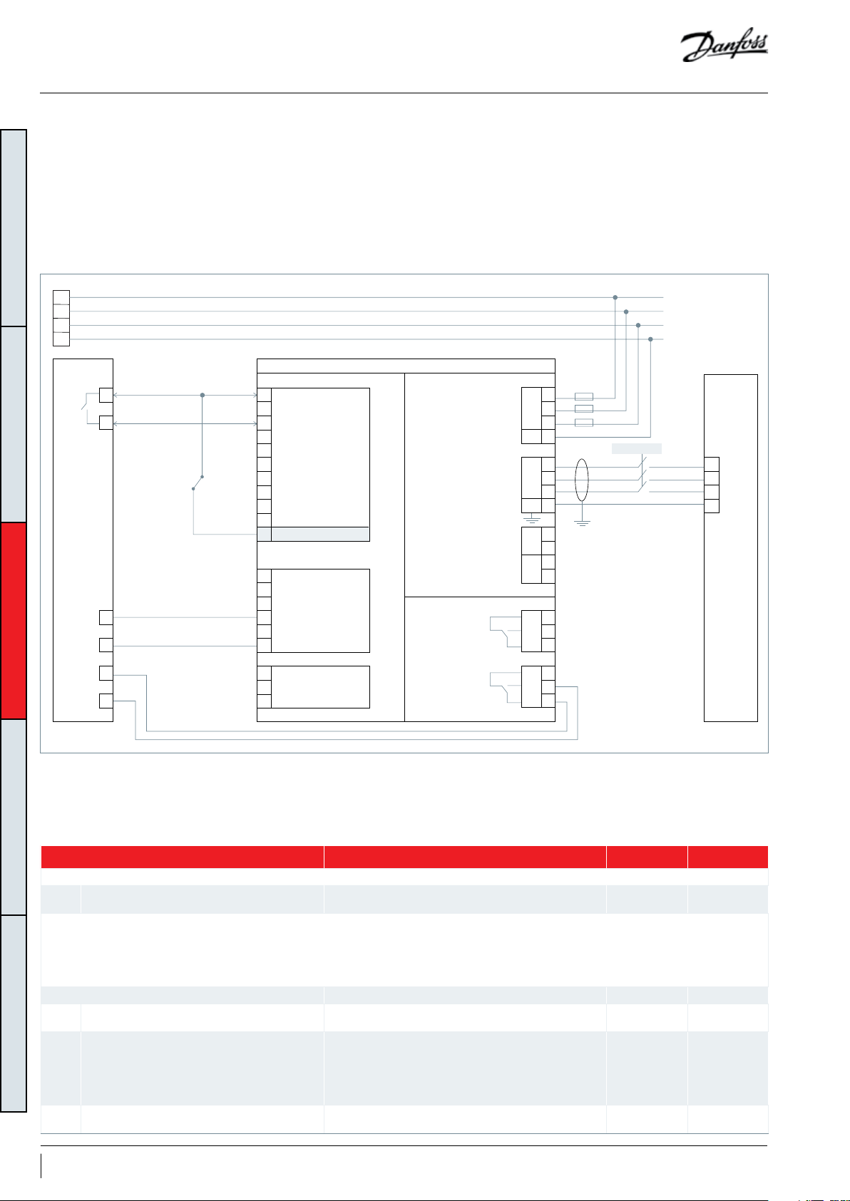
The frequency converter is pre-set for speed
open loop control. This means that the speed setpoint is given by a 0-10V, where 0V corresponds
to the minimum compressor speed and 10V is
maximum compressor speed.
SCHEMATIC DIAGRAM
CDS 303
+24V CC (150mA max.)
12
+24V CC
13
Digital Input
18
Digital Input
19
Digital Input
27
29
Digital Output
Digital Input
32
Digital Input
33
Digital Input Common
20
37
Safe Stop Input
Analog Output Common
39
42
Analog Output 1 0/4-20mA
+10V CC (15mA max.)
50
53
Analog Input 1
Analog Input 2
54
55
Analog Inputs Common
Relays
3 phase
power input
50/60Hz
Motor output
Load sharing
Brake resistor
Relay 1
The unit controller must have full control of
the compressor operation and application
protections such as compressor envelope
control, oil return management and short cycling
protection.
Below is the Danfoss proposed system
configuration and wiring.
L1 91
L2
L3
PE
U
V
W
PE
+DC
RR+
CM 01
NO
NC
Fuses
92
93
95
96
97
98
99
88-DC
89
81
82
02
03
Contactor
T1
T2
T3
PE
VZH
04
CM
NO
NC
05
06
Alarm
Digital input
61
Y
Z
COM Serial
68
P Communication
69
N RS-485
Relay 2
NOTE 1: Only relevant parameters or the ones different from factory defaults are shown.
NOTE 2: Oil boost, short cycle protection to be programmed in the unit controller
NOTE 3: Use Safe Stop for HP switch in CDS303 or use an output contactor (CDS803)
Drive parameters to adjust (See Note 1)
Drive parameters Description Value Default
Short cycle protection is done by unit controller
28.00 Short cycle protection
Short cycle protection is done in drive; If short cycle protection enabled in drive, the Terminal 18 start/stop will be ignored during minimum run
time. To be able to stop compressor during this minimum run time (Low pressure trip..), it is necessary to use Terminal 27 (Par 5.12) and set it to “Coast
inverse”
If Modbus is used it is not necessary to connect terminal 27, but a “Coasting” command must be sent to be able to stop compressor in case of an alarm
during minimum run time.
28.00 Short cycle protection Short cycle protection done by the drive. Enable Enable
28.01 Interval between starts
28.02 Minimum Run time
5.12 Terminal 27 Digital input Designated for the LP switch.
Short cycle protection done in unit controller: (preferred
option)
Start command is ignored until the timer (300s) has
elapsed. Only then, can the compressor start.
The compressor cannot stop until the set time (180s) has
elapsed.
The timer starts counting following a compressor start.
Stop command is ignored.
Only a coast (inverse) command can override the time
and stop the compressor.
Disable Enable
300 sec 300sec
180 sec 180sec
[2]* Coast
inverse
coast inverse
32 AB221086441234en-001101
Page 33
Design piping
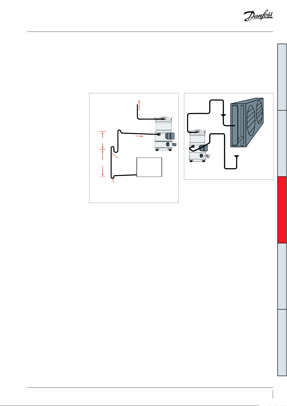
General requirements Proper piping practices should be employed to:
1. Ensure adequate oil return, even under
minimum load conditions (refrigerant speed,
piping slopes…). For validation tests see section
“Manage oil in the circuit”.
To condenser
HP
max. 4m (13ft)
max. 4m (13ft)
0.5% slope
4m/s or more
(13ft/s or more)
U-trap,
as short as possible
8 to 12m/s
(26 to 40ft/s)
0.5% slope
4m/s or more
(13ft/s or more)
U trap, as short as possible
LP
Evaporator
2. Avoid condensed liquid refrigerant from
draining back to the compressor when stopped
(discharge piping upper loop). For validation
tests see section “Manage off cycle migration”.
General recommendations are described in the
figures below:
Upper loop
HP
LP
Condenser
3D flexibility
GENERAL INFORMATIONPRODUCT INFORMATIONSYSTEM DESIGNINTEGRATION INTO SYSTEMORDERING INFORMATION
3. Piping should be designed with adequate
three-dimensional flexibility to avoid excess
vibration. It should not be in contact with the
surrounding structure, unless a proper tubing
mount has been installed. For more information
on noise and vibration, see section on: “Sound
and vibration management”.
4. The design in this guideline is for short circuit
application. However, for long circuit and split
system application, an oil separator and an
external non-return valve are mandatory to use.
33AB221086441234en-001101
Page 34
Design compressor mounting
General requirements
Single requirements
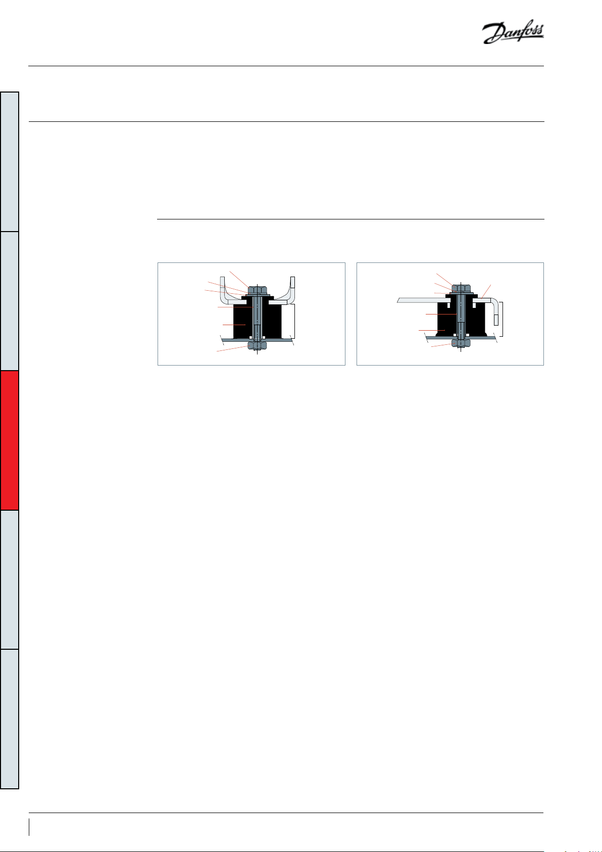
GENERAL INFORMATIONPRODUCT INFORMATIONSYSTEM DESIGNINTEGRATION INTO SYSTEMORDERING INFORMATION
Compressors used in single applications must be
mounted with flexible grommets.
Maximum inclination from the vertical plane
while operating must not exceed 3 degrees.
VZH compressors come delivered with four
rubber mounting grommets and metal sleeve
liners that serve to isolate the compressor from
the base frame. These grommets must always
The required bolt size for the VZH088 & 117
compressors is HM8-40. This bolt must be
tightened to a torque of 15 Nm (11 ft/lbs.).
HM 8 bolt
Lock washer
Flat washer
Steel mounting
sleeve
Rubber grommet
Nut
15 mm
(0.59 inch)
During operation, the maximum inclination from
the vertical plane must not exceed 3 degrees.
be used to mount the compressor in a single
application. The grommets must be compressed
until contact between the flat washer and
the steel mounting sleeve is established. The
grommets attenuate to a great extent the
transmission of compressor vibrations to the base
frame.
The required bolt size for VZH170 compressors
is HM8-55 and must be tightened to a torque of
21Nm (15 ft/lbs).
HM 8 bolt
Lock washer
Flat washer
Steel mounting sleeve
Rubber grommet
Nut
Compressor
base plate
28 mm
(1.10 inch)
34 AB221086441234en-001101
Page 35
Manage oil in the circuit
Requirement
R
Oil level must be visible or full in the sight
glass when the compressor is running and when
all compressors of the circuit are stopped.
System evaluation
Single compressor
Non split Test N°1
1. Since each installation is unique, test can not validate
Split
the oil return, Oil separator is mandatory
2. Pay special attention to “Piping design” on field
3. Oil level must be checked and adjusted at
commissioning.
Test, criteria and solutions
Test N° Purpose Test condition Pass criteria Solutions
A
1. Top-up with oil, generally 3% of
the total system refrigerant charge
1
Check proper
oil return
Lowest foreseeable evaporation,
and highest foreseeable
condensation.
Minimum speed running 6 hours.
For reversible system, perform test
in both heating and cooling mode.
Oil level must be visible or full in the
sight glass when the compressor is
running.
(in weight). Above 3% look for
potential oil trap in the system.
2. Adjust oil boost function, for more
details see section”Oil management
logic”.
3. Oil separator can be added
GENERAL INFORMATIONPRODUCT INFORMATIONSYSTEM DESIGNINTEGRATION INTO SYSTEMORDERING INFORMATION
35AB221086441234en-001101
Page 36
Manage sound and vibration
Typical sounds and vibrations in systems can be
broken down into the following three categories:
• Sound radiation (through air)
• Mechanical vibrations (through parts and
structure)
Compressor sound radiation
For sound radiating from the compressors,
the emission path is air and the sound waves
are travelling directly from the machine in all
GENERAL INFORMATIONPRODUCT INFORMATIONSYSTEM DESIGNINTEGRATION INTO SYSTEMORDERING INFORMATION
Frequency
Model
VZH088
VZH117
VZH170
Average sound power for reference at ARI A/C conditions measured in free space.
Note: running sound level for 575V VZH is preliminary data
RPS
30 70 64
60 78 73 77 72 79 73
90 86 80 85 79 88 82
30 73 67
60 82 77 80 75 82 76
90 88 83 87 81 91 85
30 72 66
60 84 78 85 78 85 79
90 95 90 94 89 95 89
Without
accoustic
hood (dBA)
directions.
200V 400V 575V
With accoustic
hood (dBA)
Acoustic hood
code
120Z0510
(single
version)
120Z0512
(manifolding
/unified
version)
120Z0514
(single
version)
120Z0516
(manifolding
/unified
version)
120Z0519
(single
version)
120Z0520
(manifolding
/unified
version)
Without
accoustic
hood (dBA)
69 62
71 64
72 65
With accoustic
hood (dBA)
• Gas pulsation (through refrigerant)
The following sections focus on the causes and
methods of mitigation for each of the above
sources.
Sound levels are as follows:
• For compressors running alone:
Acoustic hood
code
120Z05 09
(single
version)
120Z0511
((manifolding
/unified
version)
120Z0513
(single
version)
120Z0515
(manifolding
/unified
version)
120Z0517
(single
version)
120Z0518
(manifolding
/unified
version)
Without
accoustic
hood (dBA)
72 66
72 66
77 71
With accoustic
hood (dBA)
Acoustic hood
120Z05 09
version)
120Z0511
(manifolding
version)
120Z0513
120Z0515
(manifolding
120Z0517
version)
120Z0518
(manifolding
version)
code
(single
/unified
(single
version)
/unified
version)
(single
/unified
Mitigations methods:
We can consider two means to reduce
compressors sound radiations:
1. Acoustic hoods are quick and easy to install
and do not increase the overall size of the
compressors. Acoustic hoods are available from
Danfoss as accessories.
Refer to the table above for sound levels,
attenuation and code numbers.
2. Use of sound-insulation materials on the inside
of unit panels is also an effective means to reduce
radiation.
36 AB221086441234en-001101
Page 37

Manage sound and vibration
Mechanical vibrations
A compressor generates some vibrations that
propagate into the surrounding parts and
structure. The vibration level of a VZH compressor
alone does not exceed 127 µm peak to peak.
However, when system structure natural
frequencies are close to running frequency,
vibrations are amplified due to resonance
phenomenon.
A high vibration level is damageable for piping
reliability and generates high sound levels.
Mitigations methods:
1. Danfoss VZH scroll compressors are designed
to produce minimal vibration during operations.
To ensure minimum vibrations transmission
to the structure, strictly follow mounting
requirements (mounting feet, rails etc..). For
further information on mounting requirements,
please refer to “Design compressor mounting”.
2. Ensure that there is no direct contact (without
insulation) between vibrating components and
structure.
This could be challenging on a variable system as
all resonant frequencies between min speed to
maximum speed will be exited.
It is mandatory to check that piping vibrations
are acceptable across speed range. This test
can be done by increasing slowly speed and
monitoring piping behavior through, strain gage,
acceleration, or displacement measurement.
As alternative visual check with strobe light can
also emphasis high piping displacement.
If some resonant frequencies generate high
piping vibration, problem can be solved by
increasing piping stiffness with brackets or
changing layout. Dampers can also be installed
to mitigate vibration.
If some frequencies continue to produce
unacceptable vibration levels, speed by-pass is
adjustable in the frequency converter, in order
to avoid some frequency ranges. Four by-pass
ranges are adjustable, and settings can be made
in parameter group 4.6x
GENERAL INFORMATIONPRODUCT INFORMATIONSYSTEM DESIGNINTEGRATION INTO SYSTEMORDERING INFORMATION
Gas pulsation
3. Resonance phenomenon
To avoid resonance phenomenon, pipings and
frame must have natural frequencies as far as
possible from running frequencies.
The Danfoss VZH scroll compressor has been
designed and tested to ensure that gas pulsation
is optimized for the most commonly encountered
air conditioning pressure ratio. Manifolded
compressors are equivalents to lagged sources
of gas pulsation. Therefore, pulse level can vary
during time.
Mitigations methods:
If an unacceptable level is identified, a discharge
muffler with the appropriate resonant volume
and mass can be installed.
37AB221086441234en-001101
Page 38
Manage speed limit
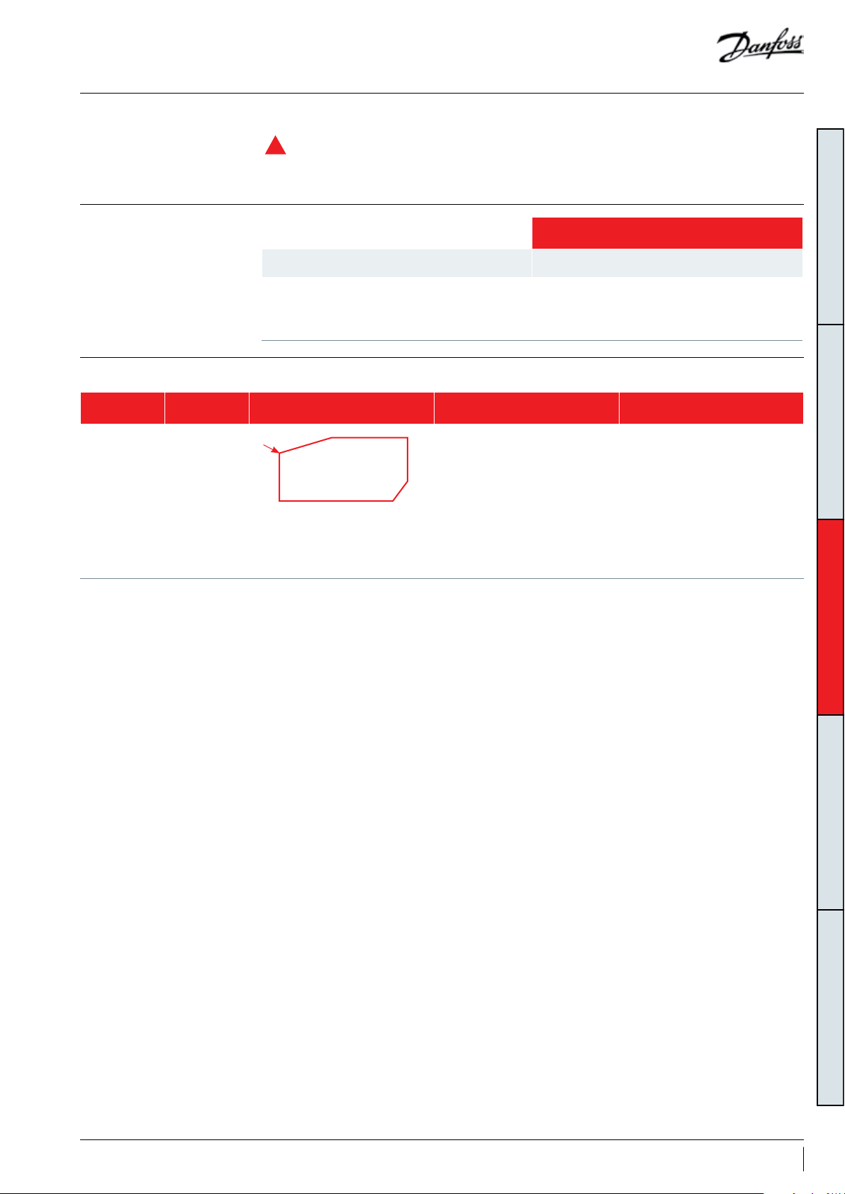
Speed limit requirement
Speed limit guerantees compressor
R
reliability and must be respect. In drive control
logic, default setting values have been qualified
by Danfoss. Customer could change the default
values in the acceptable range if the changes
have been qualified by OEM.
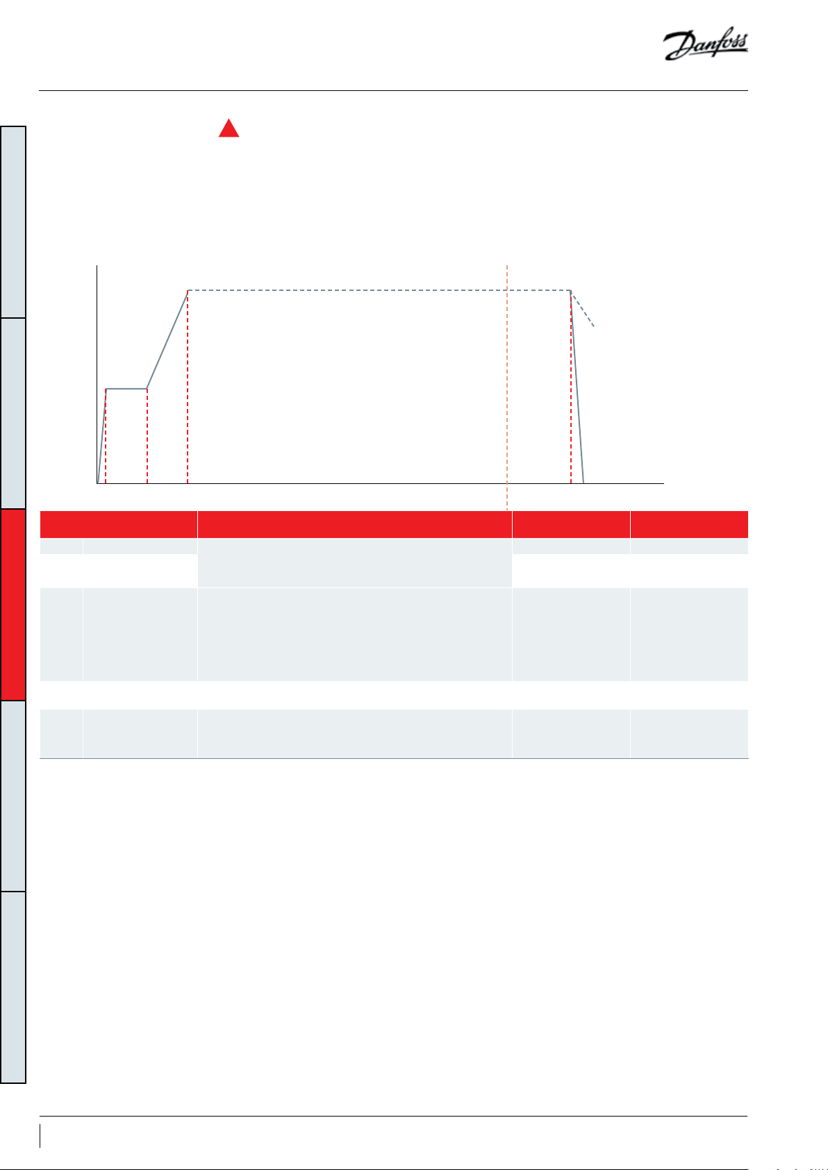
Start/Stop/Ramp setting
GENERAL INFORMATIONPRODUCT INFORMATIONSYSTEM DESIGNINTEGRATION INTO SYSTEMORDERING INFORMATION
6000
P3-41
Ramp 1 ramp up time
Speed (RPM)
Start delay
Start
P1-71
speed 1-74
P3-82
Start ramp
up time
0
Drive parameters Description
1.71 Start delay (s) Start-up sequence: at start, compressor runs at start speed (1.74)
1.74 Start speed (RPS) 30rps 1800rpm
3.41
3.42
3.82
Ramp 1 ramp up
time (s)
Ramp 1 ramp down
time (s)
Starting/stopping
ramp Time (s)
during the Start delay (1.71)
During this time the speed set-point is ignored
Defines speed ramp up slope.
Ramp 1 ramp up time (s) is the time it takes to increase
compressor speed from 0rps to 90rps. It is a linear ramp thus
gives constant acceleration during ramping.
Eg: if current speed is 55rps and desired speed is 100rps, then
compressor will take 90sec (180sec/90rps)*(100-55)rps=90sec
Defines speed ramp down slope. in similar way that ramp-up. 180sec 15-360 0s
Fast acceleration from standstill to minimum speed with a quick
ramp.
The start / stop command bypasses the normal ramp time and
the frequency converter ramps the compressor fast.
Ramp 1 ramp down time
P3-42
Stop
P3-82
Ramp 1 ramp down time
Time (s)
Default value
(recommended)
60sec 10-300s
1800-3600rpm
180sec 15-3600s
2sec 0-5s
Range
30-60rps
38 AB221086441234en-001101
Page 39

Manage superheat
Requirement
System evaluation
During normal operation, refrigerant enters
the compressor as a superheated vapor. Liquid
flood back occurs when a part of the refrigerant
entering the compressor is still in liquid state.
In steady state conditions,
• the expansion device must ensure a suction
superheat within 5K to 30K (9 to 54°F).
• Oil superheat must be higher than 10K (18°F).
Use the table in relation with the application to
quickly evaluate the potential tests to perform.
Application Tests to perform
Non reversible Liquid flood back test
Reversible
Liquid flood back test
Defrost test
Liquid flood back can cause oil dilution and, in
extreme situations lead to liquid slugging that
can damage compression parts.
In transient conditions,
• cumulative time with oil SH below 10K should
not exceed 1700h during lifetime and not last
more than 60s per event.
GENERAL INFORMATIONPRODUCT INFORMATIONSYSTEM DESIGNINTEGRATION INTO SYSTEMORDERING INFORMATION
39AB221086441234en-001101
Page 40
Manage superheat
Test, criteria and solutions
Test N° Purpose Test condition Pass criteria Solutions
GENERAL INFORMATIONPRODUCT INFORMATIONSYSTEM DESIGNINTEGRATION INTO SYSTEMORDERING INFORMATION
Liquid flood
back test
Steady-state
Transi ent
Liquid flood back testing must be
carried out under expansion valve
threshold operating conditions:
•Lowest foreseeable evaporation,
and highest foreseeable
condensation.
•Minimum speed running.
For reversible system, perform test
in both heating and cooling mode
A
Tests must be carried out with most
unfavorable conditions :
• fan staging,
• compressor staging
• …
Suction superheat >5K(9°F)
1. Check expansion valve selection
and setting.
-For Thermostatic expansion valve
(TXV) check bulb position...
-For Electronic expansion valve
(EXV) check measurement chain and
PID....
2. Add a suction accumulator*.
Oil superheat shall not be more than
30 sec below the safe limit (10K/18°F)
Check liquid
Defrost test
*Suction accumulator offers protection by trapping the liquid refrigerant upstream from the compressor. The accumulator should be sized at least 50 % of the total system
charge. Suction accumulator dimensions can impact oil return (gas velocity, oil return hole size…), therefore oil return has to be checked according to section “Manage oil in the
circuit”.
floodback
during defrost
cycle
Defrost test must be carried out
in the most unfavorable condition
(at 0°C (32°F) evaporating
temperature).
Oil superheat shall not be more than
30 sec below the safe limit (10K/18°F)
1. Check defrost logic.
In reversible systems, the defrost
logic can be worked out to limit
liquid floodback effect. (for more
details see “Control Logic”).
2. Add a suction accumulator*.
Oil temperature sensor must be placed between
oil sight glass and compressor baseplate. Some
thermal paste shall be used to improve the
conductivity. The sensor must also be correctly
thermally insulated from the ambiance.
The Oil superheat is defined as:
(Oil temperature - Evaporating temperature)
40 AB221086441234en-001101
Page 41

Manage off cycle migration
Requirement
System evaluation
R
Off -cycle refrigerant migration happens:
• when the compressor is located at the coldest
part of the installation, refrigerant vapor
condenses in the compressor.
• or directly in liquid-phase by gravity or pressure
difference.
• Compressor can tolerate occasional flooded
start, but it should remain exceptional situation
and unit design must prevent that this situation
happen at each start
When the compressor restarts, the refrigerant
diluted in the oil, or stored in evaporator,
generates poor lubrication conditions, and may
reduce bearings life time. In extreme situations,
this leads to liquid slugging that can damage the
compressor scroll set.
• Right after start, liquid refrigerant must not flow
massively to compressor
• The charge limit is a threshold beyond some
protective measures must be taken to limit risk
of liquid slugging and extreme dilution at start.
Use the table below in relation with the system
charge and the application to quickly define
necessary safeties to implement.
Application BELOW charge limit ABOVE charge limit
Ensure tightness between condenser & evaporator when system is OFF
• Thermostatic expansion Valve (TXV) , Liquid Line Solenoid Valve LLSV** strongly
All
Non split No test or additional safeties required
recommended
• Electronic expansion valve (EXV) must close when system stop including in power shut
down situation
• Surface Sump Heater *
• External Non-Return Valve
GENERAL INFORMATIONPRODUCT INFORMATIONSYSTEM DESIGNINTEGRATION INTO SYSTEMORDERING INFORMATION
Since each installation is unique, refrigerant charge may vary
Split
• Surface Sump Heater *
• Liquid Line Solenoid Valve**+ pump-down cycle***
• External Non-Return Valve
Charge limit is defined in table below:
Single
Models Refrigerant charge limit
(kg) (lb)
VZH088 6.0 13
VZH117 8.0 18
VZH170 13. 0 29
41AB221086441234en-001101
Page 42

Manage off cycle migration
GENERAL INFORMATIONPRODUCT INFORMATIONSYSTEM DESIGNINTEGRATION INTO SYSTEMORDERING INFORMATION
*Surface Sump heater
The surface sump heater are designed to protect
the compressor against off-cycle migration of
refrigerant.
For VZH088-117 the surface sump heater is
Compressor Surrounding
Ambient
Unit has enclosure, no wind 48W SSH
Unit has no enclosure, with
wind
Unit has no enclosure,
wind >5m/s (ft/s)& ambient
temperature <-5°C
Surface Sump Heater
80W SSH
80W SSH + additional
SSH/thermal insulation
For VZH170, the 56W surface sump seater is
located below the sump, associated with a
thermal insulation.
The heater must be turned on whenever all the
compressors are off.
Surface sump heater accessories are available
from Danfoss (see section “Accessories”).
located on the compressor shell.
For better standby energy consumption, Danfoss
provides 48W and 80W two optional surface
sump heater. The selection of surface sump
heater could refer to below principle:
VZH088-117
VZ H170
**Liquid line solenoid valve (LLSV)
A LLSV is used to isolate the liquid charge
on the condenser side, thereby preventing
against charge transfer to the compressor
during off -cycles. The quantity of refrigerant
on the low-pressure side of the system can be
further reduced by using a pump-down cycle in
association with the LLSV.
***Pump-down cycle
By decreasing pressure in the sump, pump down:
• Evacuates refrigerant from oil
• Set the sump saturating pressure much
lower than ambiance temperature and due
to that, avoid refrigerant condensation in the
compressor.
• Pump-down must be set higher than
2.3 bar(g) / 33(psig).
For more details on pump-down cycle see
section “Control Logic”.
42 AB221086441234en-001101
Page 43

Manage operating envelope
Requirement
Single envelope control
R
The operating envelope for VZH scroll
compressors is given in the figures below and
guarantees reliable operations of the compressor
for steady-state operation.
Moreover, the discharge gas temperature must
not exceed 135°C (275°F). Steady-state operation
envelope is valid for a suction superheat within
5K to 30K (9°F to 54°F) range.
VZH operating map - 575V/400V/208V
-22 -4 5-13 14 23 32 41 50 59 68
75
70
65
60
55
50
45
40
35
30
25
Condensing temperature (°C)
20
15
-30 -20 -15-25 -10 -5 0 5 10 15 20
30-90rps
High PR (5-10K)
(9°F-18°F)
Evaporating temperature (°C)
25-100rps
30-90rps
Low PR (5-10K)
(9°F-18°F)
(°F)
167
158
149
140
131
122
113
104
95
86
77
68
59
GENERAL INFORMATIONPRODUCT INFORMATIONSYSTEM DESIGNINTEGRATION INTO SYSTEMORDERING INFORMATION
Note: for superheat above 10K, the envelop will narrow down based on 135°C discharge temperature restriction.
Note: Red and Gray filled area are limited to 30-90rps.
for 380V power input, permitted highest condensing temperature will decrease accordingly:
-High PR: 25-100rps, condensing temperature from 60°C to 56°C (140°F to 133°F); 30-90rps, condensing temperature from 68°C to 65°C (154°F to 149°F).
-Low PR: 25-100 rps, condensing temperature from 60°C to 56°C; (140°F to 133°F) 30-90 rps, condensing temperature from 63°C to 62°C (145°F to 144°F).
Pressure settings
Working pressure range high side
Working pressure range low side 2.3 - 11.6 33.36 - 168.24
Maximum high pressure safety switch setting 45 652.67
Minimum low pressure safety switch setting * 1.5 21.75
Minimum low pressure pump-down switch setting
*LP safety switch shall never be bypassed.
1.5 bar below nominal evaporating pressure
with minimum of 2.3 bar(g)
bar (g) psi (g)
High PR 13.5 - 44.5
Low PR 13.5 - 40
R410A
High PR 195.8 - 645.4
Low PR 195.8 - 580.1
21 psi below nominal evaporating pressure
with minimum of 33 psig
43AB221086441234en-001101
Page 44

Manage operating envelope
System evaluation
GENERAL INFORMATIONPRODUCT INFORMATIONSYSTEM DESIGNINTEGRATION INTO SYSTEMORDERING INFORMATION
Protection required
• HP switch*
• LP switch*
• DGT set @ 135°C
(275°F) if necessary see
Discharge T° protection
• Measurements of
suction and discharge
pressure, unit controller
with is permanently
maintaining compressor
within its envelope
VZH drive can only protect the compressor from
over current. To manage operating envelop, an
advanced envelope protection principle needs
to be used with variable speed compressors.
This solution offers much better protection than
basic protection, and also offers the possibility
to adjust running conditions to avoid tripping
(for example reduce compressor speed when
reaching high pressure limit).
The advanced protection principle is based
on a permanent measurement of suction
and discharge pressure. Unit controller is
DGT
25-100rps
30-90rps
LP Switch
Condensing pressure control
permanently checking that the compressor is
running within the defined envelope.
When compressor reach a limit, controller can
act on different parameter to avoid unit tripping.
On top of suction and discharge pressure
limitations, the discharge T° must remain below
135°C (275°F).
Low pressure switch and high pressure switch
remain necessary as an ultimate protection.
HP Switch
30-90rps
MOP Control
Minimum pressure ratio
Controller manages speed limit according to
evaporating Tº & condensing T°
Perform oil boost test 1 described below
For Minimum pressure ratio,
Condensing pressure control, Discharge T°,
Protection logic are integrated in controller
* for more details see “Control Logic”
Test Purpose Test conditions Pass criteria Solutions
Check reaction of system to oil
1
boost
Stabilized the system in area
below minimum speed (2400RPM)
until oil boost happen
No safeties happen
Superheat requirement fulfilled
Modify ramp-up
Modify superheat control
44 AB221086441234en-001101
Page 45

Manage operating envelope
Bracket
Discharge temperature
protection
Discharge gas temperature (DGT) protection
is required if the high and low pressure switch
settings do not protect the compressor against
operations beyond its specific application
70
65
60
55
50
45
40
35
Cond. temp. (°C)
30
25
20
15
10
-30 -25 -20 -15
Example 1 (R410A, SH = 6K/10.8°F)
LP switch setting:
LP1 = 3.3 bar (g) (-15.5°C/4.1°F)
HP switch setting:
HP1 = 38 bar (g) (62°C/143.6°F)
Risk of operation beyond the application envelope.
DGT protection required.
LP1
DGT - limit
LP2
-10
envelope. Please refer to the examples below,
which illustrate where DGT protection is required
(Ex. 1) and where it is not (Ex. 2).
Example 1
Example 2
R410A
-5 0510 15 20
Evap. temp. (°C)
Example 2 (R410A, SH = 6K/10.8°F)
LP switch setting:
LP2 = 4.6 bar (g) (-10.5°C/13.1°F)
HP switch setting:
HP2 = 31 bar (g) (52°C/125.6°F)
No risk of operation beyond the application envelope.
No DGT protection required.
HP1
HP2
GENERAL INFORMATIONPRODUCT INFORMATIONSYSTEM DESIGNINTEGRATION INTO SYSTEMORDERING INFORMATION
A discharge gas temperature protection device
must be installed on all heat pumps. In reversible
air-to-air and air-to-water heat pumps, the
discharge temperature must be monitored
during development test by the equipment
manufacturer.
The compressor must not be allowed to cycle
on the discharge gas thermostat. Continuous
operations beyond the compressor’s operating
range will cause serious damage to the
compressor.
The discharge gas thermostat accessory kit (code
7750009) includes all components required
for installation as shown on the right. DGT
installation must respect below requirements:
• The thermostat must be attached to the
discharge line within 150 mm (5.91 inch) from
the compressor discharge port and must be
thermally insulated and tightly fixed on the
pipe.
• The DGT should be set to open at a discharge
gas temperature of 135°C (275°F) or lower..
Thermostat
Discharge line
Insulation
45AB221086441234en-001101
Page 46

Manage operating envelope
MOP (Max operating
pressure) control
GENERAL INFORMATIONPRODUCT INFORMATIONSYSTEM DESIGNINTEGRATION INTO SYSTEMORDERING INFORMATION
Condensing pressure
control
Minimum pressure ratio
In steady state, it is essential to prevent the
compressor running when evaporating T° is
higher than the specified envelope. Operating
the compressor higher than maximum
evaporating temperature will cause low viscosity
of lubricant and lead to high dilution. Eventually
the compressor will get damaged.
This protection can be achieved by using
MOP function on expansion device. MOP is a
feature added to EXV’s (also to TXV’s) that limit
the maximum suction pressure of the unit.
The customer would need to set this at the
In steady state, the condensing T° must be
maintained at a higher T° than specified in
envelope. This can be done by using fan speed
controller, or constant pressure valve. Keep
condensing pressure at a minimum level is also
important to maintain the pressure differential
across the thermostatic expansion valve and
In steady state, the pressure ratio must be a
higher T° than specified in envelope. 2 type of
control can be considered:
• Set the minimum condensing T° at 20°C (68°F)
together with MOP set at 15°C (59°F).
15°C (59°F) limit we have on our VS operating
envelope.
Regardless of EXV or TXV, customer needs to
qualify the expansion device. Testing needs to be
done at both max and min operating conditions
to guarantee the valve closes enough on the min
and opens far enough on the max.
Complementary to MOP, the unit controller can
increase compressor speed to keep evaporating
T° lower than limit.
prevent cut out on the LP protection in cold
ambient.
As an alternative the unit controller can increase
compressor speed to keep condensing T° lower
than limit.
• Unit controller monitors permanently
Condensing and Evaporating T°, and adjust
compressor speed or condensing T° to keep
running conditions within envelope.
46 AB221086441234en-001101
Page 47

Control logic
Safety control logic requirements
HP switch
LP safety switch
Tripping conditions Re-start conditions
Value Time Value Time
See Pressure settings table
from section “Manage
operating envelope”
Immediate, no delay.
No by- pass
Conditions back to normal.
Switch closed again
Manual reset
Maximum 5 auto reset during
a period of 12 hours, then
manual reset.
High pressure According to EN378-2, a high-pressure (HP) safety
switch is required to shut down the compressor.
The high-pressure switch can be set to lower
values depending on the application and
ambient conditions. The HP switch must either be
placed in a lockout circuit or consist of a manual
reset device to prevent cycling around the high-
Low pressure A low-pressure (LP) safety switch must be
used. Deep vacuum operations of a scroll
compressor can cause internal electrical arcing
and scroll instability. VZH compressors exhibit
high volumetric efficiency and may draw very
low vacuum levels, which could induce such
a problem. The minimum low-pressure safety
switch (loss-of-charge safety switch) setting is
given in the following table. For systems without
pump-down, the LP safety switch must either be
a manual lockout device or an automatic switch
Electronic expansion valve
With variable capacity systems, an electronic
expansion valve (EXV) is the strongly
recommended solution to handle refrigerant
mass flow variations. Danfoss recommends the
use of ETS products. Ramp-up and ramp-down
settings, of both EXV and compressor, must be
done with great care.
pressure limit. If a discharge valve is used, the HP
switch must be connected to the service valve
gauge port, which must not be isolated. The HP
switch must be connected to the CDS303 input
37 or an external contactor placed before and
after the drive.
wired into an electrical lockout circuit. The LP
switch tolerance must not allow for vacuum
operations of the compressor. LP switch settings
for pump-down cycles with automatic reset are
also listed in the table below. Lock-out circuit or
LP switch or series with other safety devices must
be connected to CDS303 input 27.
OEM need to set port 27 to “coast inverse or
external interlock” to get rid of minimum
running time restriction.
compressor. The EXV can also be opened, up
to a certain degree, before the start up of the
compressor.
Ramp-down of the EXV must be longer than the
ramp-down of the compressor, also to avoid low
pressure operation (except with pump-down).
GENERAL INFORMATIONPRODUCT INFORMATIONSYSTEM DESIGNINTEGRATION INTO SYSTEMORDERING INFORMATION
Ramp-up of the EXV must be shorter than
the ramp-up of the compressor, to avoid any
low pressure operation on suction side of the
Reverse rotation
protection
Due to drive protection, compressors could work
properly even if the power connection between
the drive and mains is dis-matched. However, the
wires between compressor and drive must be
connected accordingly.
Short cycle protection Short cycling protection requirements need to be
implemented in OEM unit controller. Meantime,
the factory default setting needs to be disabled
(28-00 short cycle protection change from
default setting “enable” to “disable”).
- 3 minutes minimum running time: in order to
get oil return back from circuit to compressor
sump
EXV should be closed, and remain closed,
when the compressor is off, to avoid any liquid
refrigerant entering the compressor.
To protect compressors from reverse rotation,
pressure difference could be checked as a
reference value. Use pressure sensors to monitor
pressure difference between discharge and
suction of the compressor, and for normal
operation, discharge pressure should be at least
1 bar higher than suction pressure within 30 s
running after compressor starting.
- 12 starts maximum per hour: to avoid threaten
the life time of motor and other mechanics due
to frequent starts, OEM needs to limit the starts
cycles within 12 times per hour.
- 10s minimum OFF time: to make sure discharge
valve is closed and motor is stopped before next
start, OEM needs to set the minimum off time as
10 seconds.
47AB221086441234en-001101
Page 48

Control logic
Defrost cycle logic In reversible systems, the defrost logic can be
worked out to limit liquid flood back effect by:
1. Running full load during defrost to share liquid
refrigerant between all compressors.
The following defrost logic combines both
advantages:
Compressor
GENERAL INFORMATIONPRODUCT INFORMATIONSYSTEM DESIGNINTEGRATION INTO SYSTEMORDERING INFORMATION
4WV
EXV
ON
Heating
100%
Defrost start. Stop the compressor
4 Way Valve (4WV) stays in heating mode.
EXV opened to transfer liquid from
outdoor to indoor exchanger thanks to
pressure difference
When pressures are almost balanced,
change 4WV to cooling mode.
Start the compressor with recommend values
in section ”Speed limit requirement”.
2. Transferring liquid refrigerant from one
exchanger to the other one thanks to pressures.
Defrost
4 WV stays in cooling mode.
EXV opened to transfer liquid
Defrost end. Stop the compressor
from indoor to outdoor exchanger
thanks to pressure difference
When pressures are almost balanced,
change 4WV to heating mode.
Start the compressor, with recommend
values in section ”Speed limit requirement”.
Afterwards, go to the set speed.
Pump-down logic recommendations
* EXV Opening degree and time have to be set
to keep a minimum pressure for 4 way valve
moving.
Pump down is initiated prior to shutting
down the last compressor on the circuit by
de-energizing a liquid line solenoid valve
or closing electronic expansion valve. When
suction pressure reached the cut-out pressure,
compressor is stopped, and liquid solenoid valve
or electronic expansion valve remains closed.
Two types of pump-down exist:
Danfoss recommend above defrost cycle logic,
but the control logic is also system specified.
In any case, defrost logics must respect
requirements and tests described in “Manage
superheat” and “Manage operating envelope”.
• One shot pump down (preferred): when
last compressor of the circuit stops, suction
presssure is decreased 1.5 bar below nominal
evaporating pressure. Even if suction pressure
increases again, the compressor will not restart.
• Continuous pump-down: traditional pumpdow, Compressor restarts automatically when
suction pressure increases up to 4 cycles
maximum. A non-return valve in the discharge
line is recommended.
48 AB221086441234en-001101
Page 49
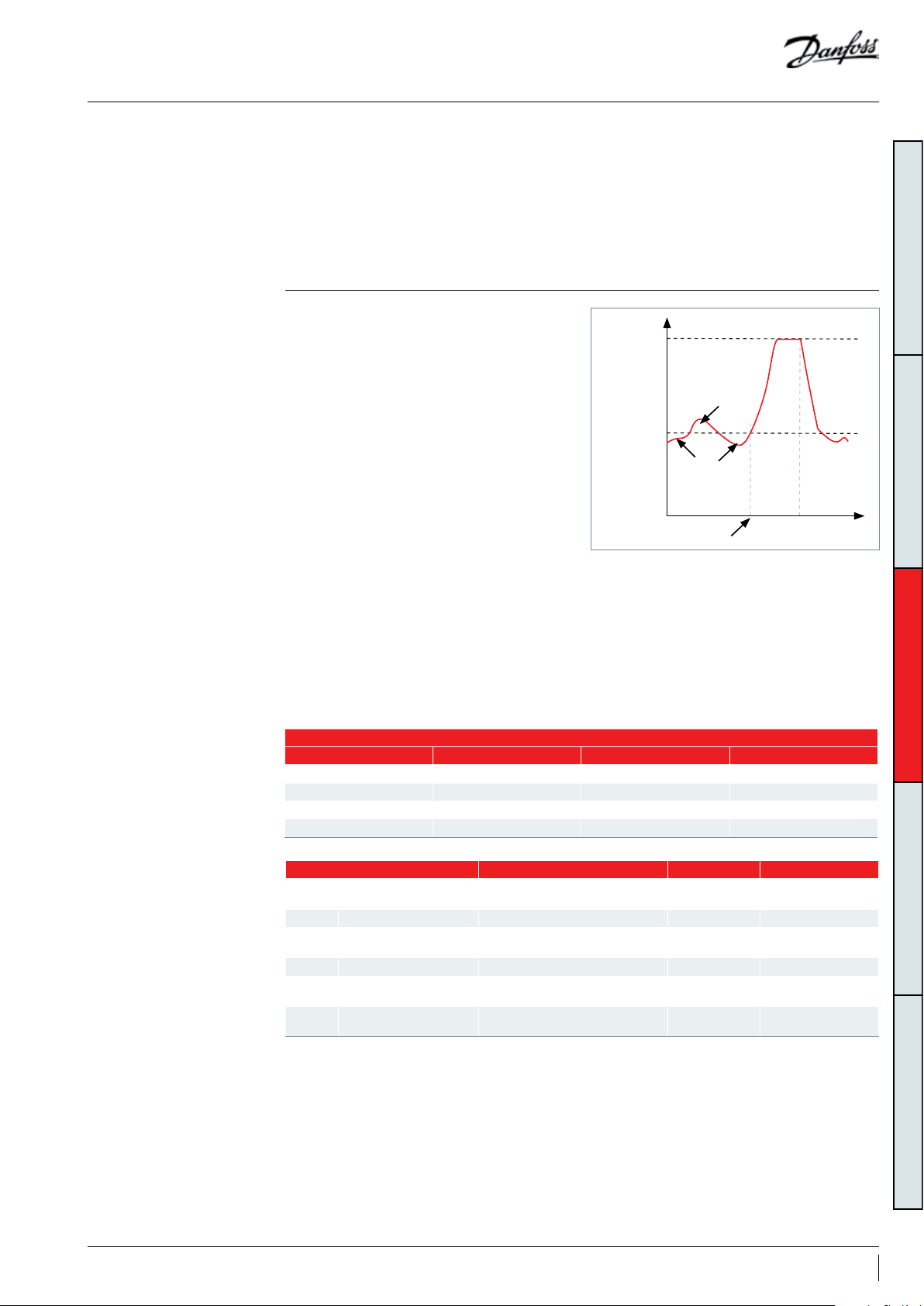
Control logic
Oil boost
CDS Drive oil boost function
An insufficient oil level can be the result of low
refrigerant velocity in pipes and heat exchangers.
An oil boost sequence consisting of increasing
refrigerant velocity for short periods, at regular
time intervals can improve oil return.
Oil boost function can be done in 2 ways
1. Using internal CDS drive oil boost function
If the compressor runs below ORM Min Speed
Limit, 28.14) for more than low speed running
time, 28-11, then function will override the unit
controller and accelerate compressor speed to
ORM Boost Speed, 28.16 for Boost duration 28.13
(28.13 does not include the ramping up time).
When the boost is finished, the compressor
speed goes back to run on reference (speed
setpoint) and the time counter is reset and
restarting from zero.
On top of that compressor will boost to ORM
Boost Speed, 28.16 at a fixed time interval as
programmed in parameter 28-12.
Feedback and status message
A feedback signal can be routed back to the unit
controller via programable digital output, relay_2
or Modbus when an oil boost is initiated.
The unit controller can take actions to keep the
system stabilized during the oil boost period.
A status message “Oil Boost” is also displayed on
the drive LCP during boost.
2. Program oil boost function in unit controller
and use optical oil level sensor to trig it.
As oil boost logic needs to increase / decrease
speed, make sure expansion device is fast
enough to maintain liquid flood back within
acceptable limit during those transients (§
Manage superheat).
28.17 ORM
Boost speed
Decrease ORM
time
28.15 ORM
Min spee d limit
Increase ORM
time
2811-ORM Low Speed
Running time expire
Boost
duration
28 .13
GENERAL INFORMATIONPRODUCT INFORMATIONSYSTEM DESIGNINTEGRATION INTO SYSTEMORDERING INFORMATION
Feedback and status message
Drive parameters Description value Default
05-02 Terminal 29 Mode Output Input
5-31 Terminal 29 Digital Output Oil boost active No Operation
5- 40.1 Function Relay Oil boost active VLT running
16-94 (read) Ext. Status Word 1000000hex (bit 24)
Drive parameters Description Default value Range
"28.10" Oil return management
"28 .11" Low speed running Threshold for boost decision 30min 1-1440mi n
"2 8.12" Fixed boost interval
"28.13" Boost duration desired duration of oil boosts 60sec 10-255s
"28.14" ORM Min speed limit
"28.16" ORM boost speed
Enables/disables Oil Return
Management
Maximum time between oil return
boosts
Now accessible with latest drive
software Please udate
Now accessible with latest drive
software Please udate
Enable On / Off
6h 1-168h
50rps 3000rpm 1500-4200rpm
70rps 4200rpm par. 28-14 - 6000rpm
49AB221086441234en-001101
Page 50
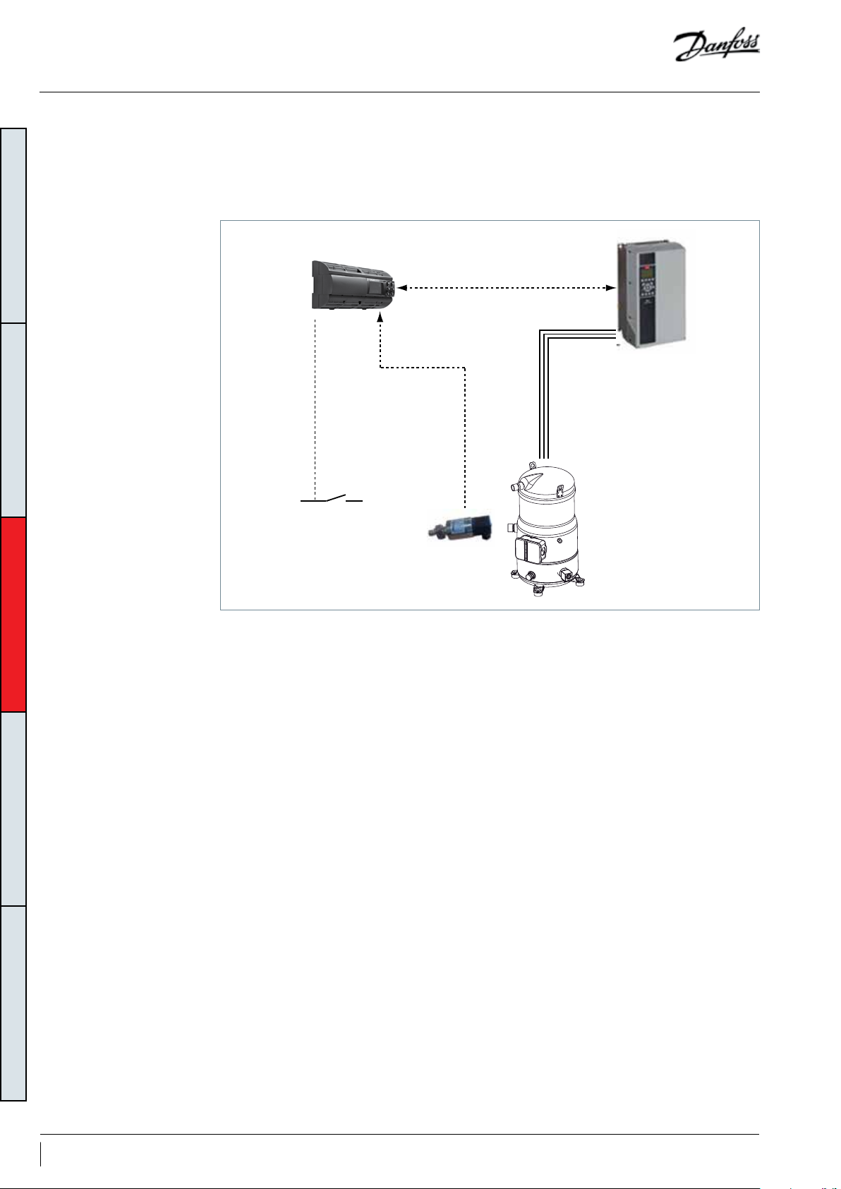
Oil sensor logic in single configuration
1. Oil management logic for single system
GENERAL INFORMATIONPRODUCT INFORMATIONSYSTEM DESIGNINTEGRATION INTO SYSTEMORDERING INFORMATION
The oil management system architecture for
single system is described as below. The oil
level is permanently monitored by OEM main
controller. When oil level is below the minimal,
OEM controller enters in oil boost mode to
OEM main controller
ModBus
Power supply
recover a proper oil level in compressor. If oil
level cannot be recovered, controller stops the
system.
Drive
Optical oil
level sensor
50 AB221086441234en-001101
Page 51
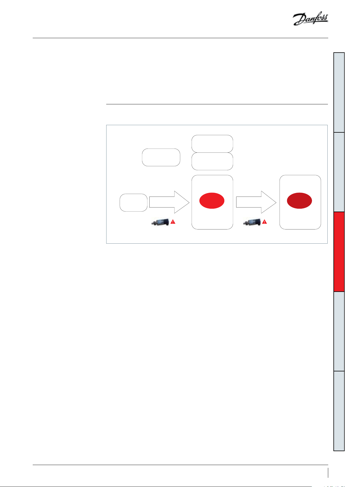
Oil sensor logic in single configuration
1S
2. Oil management description
2.1 Basic rules
2.2 Oil management
models
This specification describes the control logic to
implement in OEM controller. This control logic
must be implemented and thoroughly tested by
OEM.
The oil management control logic must include
2 steps.
Less than every
20min (TD2*)
Normal
operation
Low oil level
>5 sec
Low oil level
Max 45
sec (TD1*)
Boost
Step
As oil boost logic needs to increase speed, make
sure expansion device is fast enough to maintain
liquid flood back within acceptable limit during
those transients (Manage super heat chapter).
Oil
Oil level not
recovered
Protection
tep 2
GENERAL INFORMATIONPRODUCT INFORMATIONSYSTEM DESIGNINTEGRATION INTO SYSTEMORDERING INFORMATION
Step 1(oil boost)
If oil level sensor detects low level for more
than 5 seconds, oil is trapped in the system.
Oil boost is activated(VS speed is increased). It
considerably increases refrigerant velocity in the
system and recovers oil.
TD1 is the maximum time to complete step 1. If
oil is not recovered within TD1 switch to step 2. If
oil is recovered within TD1 come back to normal
operation.
TD2 is the minimum interval between two step
1. In case of low oil level detection within a time
<TD2, switch to step 1.
Step 2(Protection)
If oil is still lower than limit after completed
step 1, or if oil level drop within a time <TD2,
controller must enter in protection mode, and
stop the system in alarm.
Note: TD time is adjustable.
51AB221086441234en-001101
Page 52
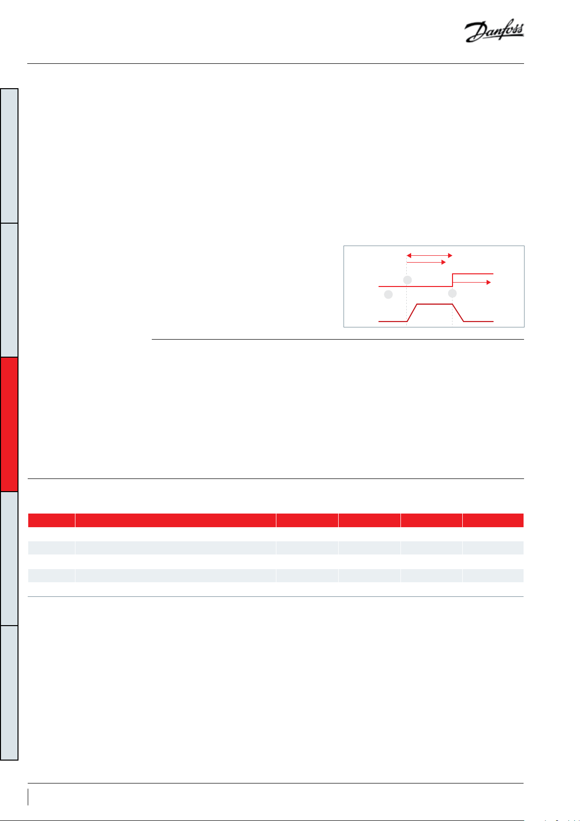
Oil sensor logic in single configuration
2.3 Steps description
2.3.1 Oil boost
GENERAL INFORMATIONPRODUCT INFORMATIONSYSTEM DESIGNINTEGRATION INTO SYSTEMORDERING INFORMATION
2.3.2 Protection
Function description
Return oil trapped in the system to compressor
by increasing refrigerant mass-flow in the system.
Enter condition
Low oil level in VS compressor detected by oil
level sensor.
Cancel condition
High oil level in VS compressor detected by oil
level sensor.
OR
t1>TD1, Oil boost duration exceeds Maximum Oil
boost duration
Function description
Stop the compressor to prevent short of oil
running.
Enter condition
Low oil level in VS compressor detected by oil
level sensor.
AND
(t1>TD1, Oil boost duration exceeds TD1 OR
t2<TD2, Interval between two Oil boost
is < TD2)
Control sequence
1. At initial state, VS (variable speed compressor)
is on.
2. Low oil level detected in compressor. Reset and
Start t1.
3. VS compressor speed must increase to Fboost
4. When High oil level detected in VS compressor.
• VS compressor speed must be decreased to the
initial speed
• Reset and start t2
• Reset t1
Max TD1
t1
t2
1
variable speed
compressor
2
Oil lack
3
FBoost
Cancel condition
Manual Reset
Control sequence
Stop VS compressor
Reset t1
Reset t2
2.4 Parameter and
variable table
Name Tex t Attribute Range Default Unit
Fboost Boost action frequency Parameter 25-100 70 rps
TD1 Maximum oil boost duration Parameter 10-240 45 Second
TD2 Interval minimum between two oil boost Parameter 10-60 20 Minutes
t1 Oil boost timer Variable Second
t2 Interval minimum between two oil boost Variable Minutes
52 AB221086441234en-001101
Page 53
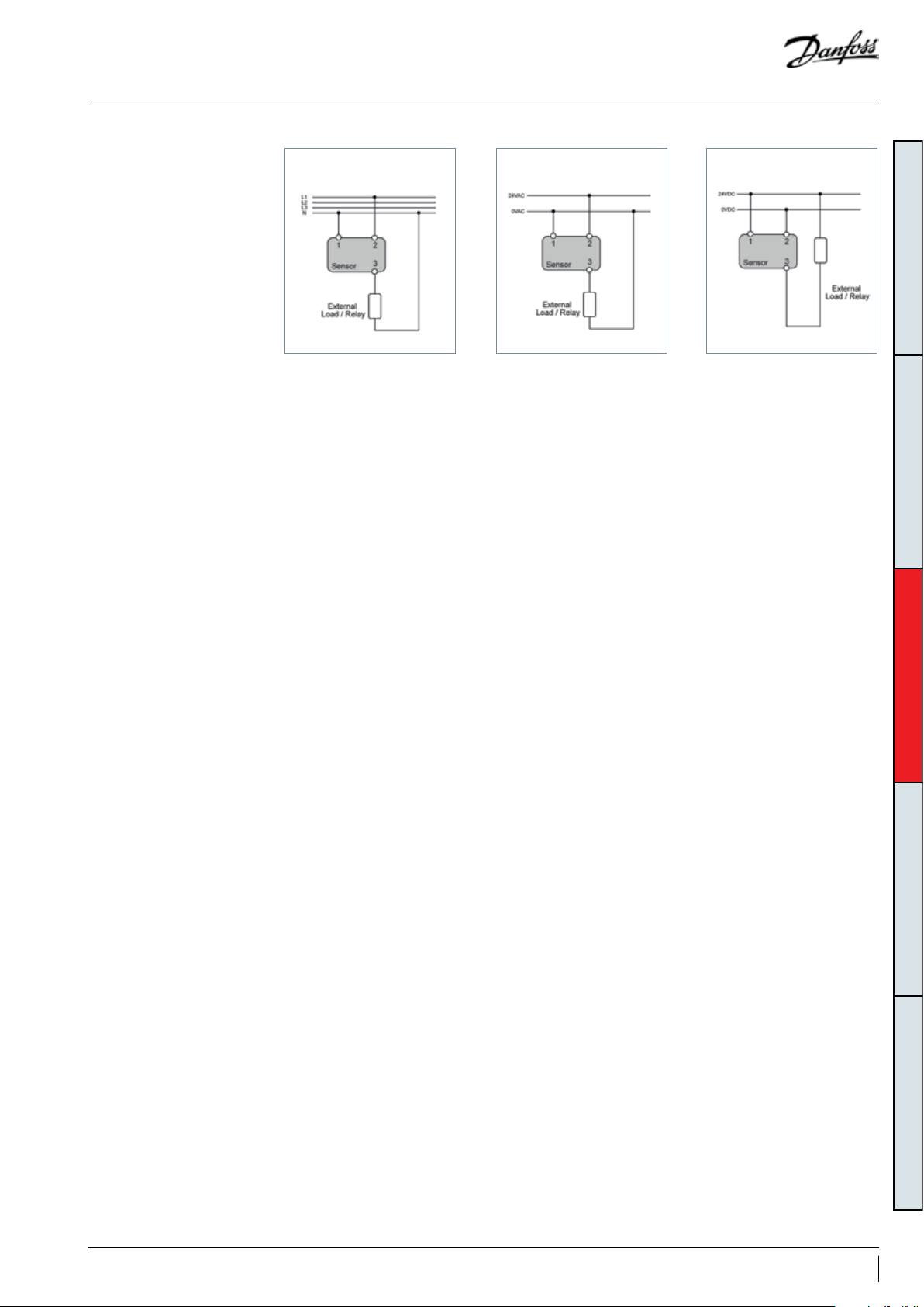
24VDC MODEL
24VAC MODEL
24VDC MODEL
Oil sensor logic in single configuration
2.5 Sensor Wiring diagram
230VAC MODEL
24VAC MODEL
An TEKLAB LC-XN optical-electrical level sensor
is fixed on the inverter compressor. The oil
level sensor monitors the compressor oil level
and sends oil level signal to an external relay
(provided by OEM ). Regarding this oil level
signal, a 5±2 seconds delay is recommended to
be used to consider the oil level fluctuation which
may trigger false alarms.
- Lack of oil: Circuit between 2 and 3 will be
opened internally, there will be no current
24VDC MODEL
flowing through load or coil of external relay. For
relay, output is open.
- Enough oil: Circuit between 2 and 3 will be
closed internally, there will be current flowing
through load or coil of external relay. For relay,
output is closed
For customers who needs UL certificates, please
order 24V AC/DC sensor.
GENERAL INFORMATIONPRODUCT INFORMATIONSYSTEM DESIGNINTEGRATION INTO SYSTEMORDERING INFORMATION
53AB221086441234en-001101
Page 54
Reduce moisture in the system
Requirements
GENERAL INFORMATIONPRODUCT INFORMATIONSYSTEM DESIGNINTEGRATION INTO SYSTEMORDERING INFORMATION
Solutions
Excessive air and moisture
• can increase condensing pressure and cause
excessively high discharge temperatures.
• can create acid giving rise to copper platting.
• can destroy the lubricating properties of the oil.
VZH compressors are delivered with < 100 ppm
moisture level.
At the time of commissioning, system moisture
content may be up to 100 ppm.
To achieve this requirement, a properly sized
and type of drier is required. Important selection
criteria’s include:
• driers water content capacity,
• system refrigeration capacity,
• system refrigerant charge.
All these phenomena can reduce service life
and cause mechanical and electrical compressor
failure.
During operation, the filter drier must reduce this
to a level between 20 and 50 ppm.
For new installations with VZH compressors with
PVE oil, Danfoss recommends using the Danfoss
DML (100% molecular sieve) solid core filter drier.
54 AB221086441234en-001101
Page 55

Assembly line procedure
Compressor storage
Compressor holding charge
Handling
Store the compressor not exposed to rain,
corrosive or flammable atmosphere between
-35°C to 70°C (-31°F to 158°F) when charged
Each compressor is shipped with a nominal dry
nitrogen holding charge between 0.3 and 0.7
bar (4 psi and 10psi) and is sealed with elastomer
plugs.
Respect the following sequence:
• Remove the nitrogen holding charge via the
suction Schrader valve to avoid an oil mist blow
out.
Each Danfoss VZH scroll compressor is
equipped with one lift ring on the top shell.
• Always use one lift ring and discharge tube
when lifting the compressor.
• Use lifting equipment rated and certified for
the weight of the compressor or compressor
assembly.
• A spreader bar rated for the weight of the
compressor is highly recommended to ensure a
better load distribution.
with nitrogen and between -35°C (-31°F) and
Ts max value (see section “Pressure equipment
directive”) when charged with R410A refrigerant.
• Remove the suction plug first and the discharge
plug afterwards to avoid discharge check valve
gets stuck in open position.
An opened compressor must not be exposed to
air for more than 20 minutes to avoid moisture is
captured by the POE oil.
• The use of lifting hooks closed with a clasp is
recommended.
• Never use the lift rings on the compressor to lift
the full unit.
Maintain the compressor in an upright position
during all handling manoeuvres (maximum of
15° from vertical).
GENERAL INFORMATIONPRODUCT INFORMATIONSYSTEM DESIGNINTEGRATION INTO SYSTEMORDERING INFORMATION
HEAVY
do not lift
manually
Spreader bar
55AB221086441234en-001101
Page 56
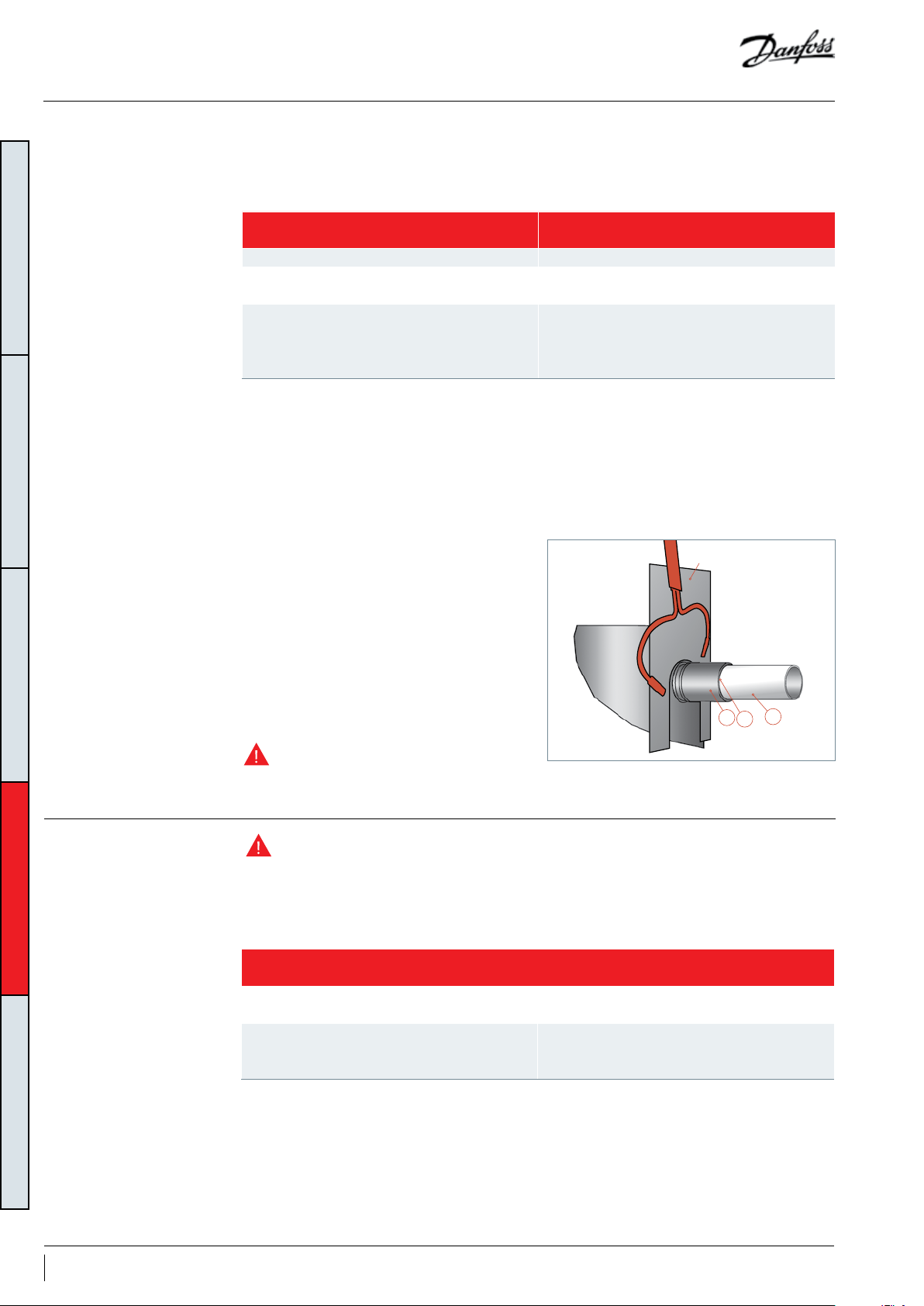
Assembly line procedure
Piping assembly Good practices for piping assembly is a pre-requisite to ensure compressor service life (system
cleanliness, brazing procedure...)
System cleanliness
Circuit contamination possible cause Requirement
Brazing and welding oxides During brazing, flow nitrogen through the system
Filings and particles from the removal of burrs in
pipe-work
GENERAL INFORMATIONPRODUCT INFORMATIONSYSTEM DESIGNINTEGRATION INTO SYSTEMORDERING INFORMATION
Moisture and air
Remove any particles and burrs generated by tube
cutting and hole drilling
Use only clean and dehydrated refrigeration grade
copper tubing
Opened compressor must not be exposed to air more
than 20 minutes to avoid moisture captured by PVE oil.
System pressure test and leak detection
Brazing procedure:
• Brazing operations must be performed by
qualified personnel.
• Make sure that no electrical wiring is connected
to the compressor.
• To prevent compressor shell and electrical box
overheating, use a heat shield and/or a heatabsorbent compound.
• Clean up connections with degreasing agent
• Flow nitrogen through the compressor.
• Use flux in paste or flux coated brazing rod.
Before eventual un-brazing of the
compressor or any system component, the
refrigerant charge must be removed.
The compressor has been strength tested
and leak proof tested (<3g/year) at the factory.
For system tests:
• Always use an inert gas such as Nitrogen or
Helium.
• Use brazing rod with a minimum of 5% silver
content.
• It is recommended to use double-tipped torch
using acetylene to ensure a uniform heating of
connection.
• To enhance the resistance to rust, a varnish on
the connection is recommended.
heat shield
C
A
B
• Pressurize the system on HP side first then LP
side.
• Do not exceed the following pressures:
56 AB221086441234en-001101
Maximum compressor test pressures
Maximum compressor test pressure high side (HP)
Maximum compressor test pressure low side (LP)
* If an external non return valve is present on the discharge line, maximum pressurizing speed must be respected to ensure pressure
equalization between LP and HP side over scroll elements.
45 bar (g) (653psig)
HP-LP<37bar (537psi)
33.3 bar(g) / (483psig) for VZH088 & 117
30.2 bar(g) / (438psig) for VZH170
LP-HP<5bar (73psi)
Maximum speed 4,8 bar/second (70psi/s)*
Page 57
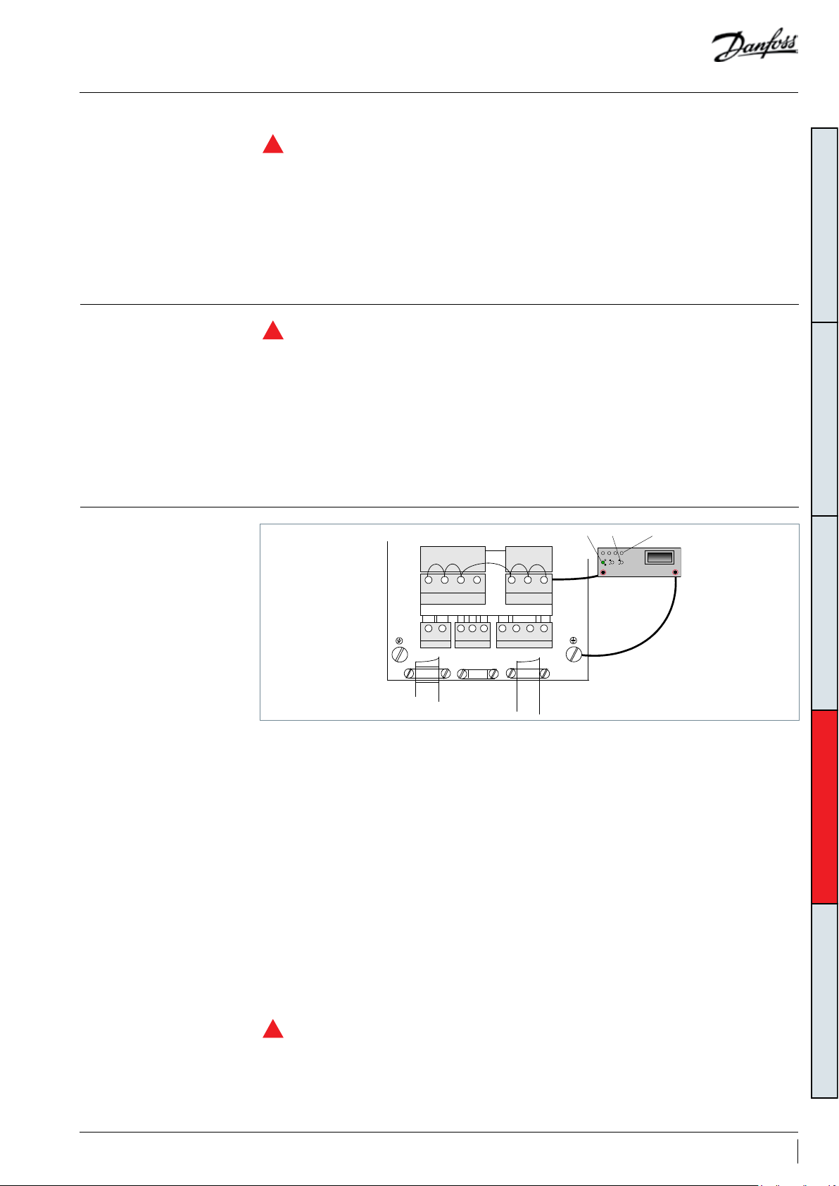
Assembly line procedure
L1 L2 L3
91 92 93
U V W PE
96 97 98 99
NETMOTOR
R- R+
81 82 01 02 03
- 24V + - DC +DC
35 36 88 89
MOTOR
NET
95
94
2 20 200 2000MOhm
+-20 ohm
M ohm
Gossen - ISOWID - 0413
M ohm
V
Ohm
On M Ohm 2000 M Ohm
Vacuum evacuation and moisture removal
Refrigerant charging
R
Requirements:
• Never use the compressor to evacuate the
system.
• Connect a vacuum pump to both the LP and HP
sides.
• Evacuate the system to a pressure of 500 μm Hg
(0.67 mbar/0.02 in.Hg) absolute.
R
Initial charge:
• For the initial charge, the compressor must not
run.
• Charge refrigerant as close as possible to the
nominal system charge.
• This initial charging operation must be done in
liquid phase between the condenser outlet and
the filter drier.
Recommendations:
• Energized heaters improve moisture removal.
• Alternate vacuum phases and break vacuum.
with Nitrogen to improve moisture removal.
For more detailed information see “Vacuum
pump-down and dehydration procedure”
TI-026-0302.
If needed, a complement of charge can be done:
• In liquid phase while compressor is running by
slowly throttling liquid in.
• Never bypass safety low pressure switch.
For more detailed information see
“Recommended refrigerant system charging
practice“ FRCC.EN.050.
GENERAL INFORMATIONPRODUCT INFORMATIONSYSTEM DESIGNINTEGRATION INTO SYSTEMORDERING INFORMATION
Dielectric strength and insulation resistance tests
It is not necessary to perform a Hipot test
(dielectric withstand test) on frequency
converters. This has already been done during
factory final test.
If a Hipot test has to be done anyway, following
instructions must be followed in order to not
damage the frequency converter:
• Compressor not connected
• L1, L2, L3, U, V, W terminals must be shorten
and connected to high voltage terminal of the
testing device.
• Ground terminal (chassis) must be connected to
low voltage terminal of the testing device.
• 2000VDC(for T2)/2150VDC( for T4)/2250VDC(for
T6) for 1 seconds must be applied
• Ramp up time 3 seconds
• Full DC voltage must be established during 2
seconds
• The current leakage during the test must be
below 1mA
• Ramp down time to 0V in 25 seconds.
When running high voltage tests of the
entire installation, frequency converter and
compressor electrical motor compressor test
can be conducted together. When conducting
a high voltage test make sure the system is not
under vacuum: this may cause electrical motor
compressor failure.
Do not use a megohm meter nor apply
R
power to the compressor while it is under
vacuum as this may cause internal damage.
57AB221086441234en-001101
Page 58

Commissioning
Preliminary check
Check electrical power supply:
• Phase order: Reverse rotation is obvious if the
compressor do not build up pressure and sound
level is abnormal high. VZH compressor will only
operate properly in one direction. If electrical
connections are done correctly between the
drive and the compressor terminals (compressor
terminals T1,T2,T3 and drive terminals U, V & W
matching), the drive will provide correct phase
supply to the compressor, and reverse rotation
will be not possible:For more details refer to
“Motor protection”.
• Voltage and voltage unbalance within tolerance:
For more details refer to section “Motor voltage”.
Initial start-up
GENERAL INFORMATIONPRODUCT INFORMATIONSYSTEM DESIGNINTEGRATION INTO SYSTEMORDERING INFORMATION
System monitoring
• Cranckcase heaters must be energized at least 6
hours in advance to remove refrigerant.
• Do not provide any power to the drive unless
suction and discharge service valves on
compressor are open, if installed.
• Energize the drive. The compressor must start,
according to defined ramp-up settings. If
the compressor does not start, check wiring
conformity.
• Check the frequency converter control panel: If
any alarm is displayed check the wiring and in
The system must be monitored after initial
startup for a minimum of 60 minutes to ensure
proper operating characteristics such as:
• Proper metering device operation and desired
superheat readings
• Suction and discharge pressure are within
acceptable levels
• Surface sump heaters must be energized at least
6 hours in advance to remove refrigerant.
• Correct oil level in compressor sump indicating
proper oil return
• Low foaming in sight glass and compressor
sump temperature 10K above saturation
temperature to show that there is no refrigerant
migration taking place
• Acceptable cycling rate of compressors,
including duration of run times.
particular the polarity of the control cables.If an
alarm is shown, refer to the frequency converter
application manual. Verify in particular the
combination of compressor, frequency
converter and refrigerant.
• Check current draw and voltage levels on
the mains. The values for the compressor
electrical motor can be directly displayed on the
frequency converter control panel.
A short cycling protection is provided in the CDS
frequency converter. It is factory preset “enabled”
with the following parameters in:
28.01 - interval between 2 starts: 300 secondes
28.02 - minimum run time: 12 seconds.
This minimum run time is set to guaranty long
enough running time at start up in order to
create enough refrigerant flow velocity in the
system to recover the oil to the compressor
sump.
• Current draw of compressor within acceptable
values (RLA ratings)
• No abnormal vibrations and noise.
Oil level checking and top-up
58 AB221086441234en-001101
In installations with good oil return and line runs
up to 15m (49.2 feet), no additional oil is required.
If installation lines exceed 15m (49.2 feet),
additional oil may be needed. 3% of the total
system refrigerant charge (in kg/lb) can be used
to roughly define the required oil top-up quantity
(in liters) but in any case the oil charge has to be
adjusted based on the oil level in the compressor
sight glass.
When the compressor is running under stabilized
conditions, the oil level must be visible in the
sight glass.
The presence of foam filling in the sight glass
indicates large concentration of refrigerant in the
oil and / or presence of liquid returning to the
compressor.
The oil level can also be checked a few minutes
after the compressor stops, the level must be
between 1/4 and 3/4 of sight glass.
When the compressor is off, the level in the
sight glass can be influenced by the presence of
refrigerant in the oil.
Top-up the oil while the compressor is idle. Use
the schrader connector or any other accessible
connector on the compressor suction line and
a suitable pump. See news bulletin “Lubricants
filling in instructions for Danfoss Commercial
Compressors” TI 2-025-0402.
Page 59

Troubleshooting
CD warning
CD switches
to Alarm
VZH Compressor
not working
Power output
yes no
from CDS303
drive ?
#12 #13
Check alarm #
GENERAL INFORMATIONPRODUCT INFORMATIONSYSTEM DESIGNINTEGRATION INTO SYSTEMORDERING INFORMATION
VZH blocked
VZH to be
replaced
Check oil level
Piping check
oil return
Reset & Start
Check alarm #
(Continue)
#14
Earth Fault
Output side
#16
Short circuit
Output side
Torque limit
Check VZH + CDS303
#30,31,32
Motor phase
compatibility
Replace
relevant part
missing
Over current
Check motor current
&Settings
Control Comp
Working load/map
Mains Shut off
& reset
#38
Internal fault
Check motor
cable
Check VZH
Motor resistance
and isolation
Correct
the fault
Mains shut-off
before
checking !
Reset &
start
Setting Error(s)
Come back to
factory settings
Incompatibility
Between
Software &
Additional option
Contact your
Local Danfoss
59AB221086441234en-001101
Page 60

Troubleshooting
Check alarm #
(Continue)
GENERAL INFORMATIONPRODUCT INFORMATIONSYSTEM DESIGNINTEGRATION INTO SYSTEMORDERING INFORMATION
#29
Drive over
temperature
Ambiant temp.
Too high or fan damaged
Electrical cabinet
Poor ventilation
Dirt on
CDS303 coil
Air by-pass
Or recycled
Missing
CDS303 back side
Metal sheet
Turn off power
Reset & start
#65 #68
Control card
Over temp.
direct wire
Check
connections
Safe stop
activated
Check 24V
On 12/13
terminals
24V supply to
terminal 37
Reset & start
Check external
controls
Check alarm #
(Continue)
#7
DC-OV
Check main power supply
voltage
Too high or
too low
Turn off power
Reset & start
#8 #36
DC-UV
Power
normal
Internal
components
damage
Contact your
Local Danfoss
Main Failure
Check power
supply voltage
Set 14-11 to
lower value
Reset & start
60 AB221086441234en-001101
Page 61

Troubleshooting
Check alarm #
(Continue)
#49
Speed limit (low)
Wrong wiring of U/V/W
Compressor bearing wear
Compressor stopped
Automatic restart
after 30s
10 restarts
before blockage
(20 possible)
#18
Start failed
GENERAL INFORMATIONPRODUCT INFORMATIONSYSTEM DESIGNINTEGRATION INTO SYSTEMORDERING INFORMATION
Minimum speed
not reached
after 2 sec.
Compressor stopped,
similar reason as A49
Automatic restart
after 30s
10 restarts
before blockage
(20 possible)
61AB221086441234en-001101
Page 62

Dismantal and disposal
GENERAL INFORMATIONPRODUCT INFORMATIONSYSTEM DESIGNINTEGRATION INTO SYSTEMORDERING INFORMATION
Danfoss recommends that compressors and compressor oil should be recycled by a
suitable company at its site.
62 AB221086441234en-001101
Page 63

Packaging
Depth
Height
Width
CD303 packaging
Single pack
Packaging
Compressor single pack
Compressor industrial pack
Frequency converter single
pack
Compressor model
Height
(mm)
Width
(mm)
Depth
(mm)
VZH088 718 565 470 70
VZH117 718 565 470 76
VZH170 765 515 450 112
Compressor model Nbr*
Length
(mm)
Width
(mm)
Height
(mm)
Gross Weight
(kg)
VZH088 8 1150 950 680 494 2
VZH117 8 115 0 950 750 544 2
VZH170 4 115 0 965 76 8 647 2
Drive
supply
voltage
T2:
Code J
T4:
Code G
T6:
code H
Drive
power
(kW)
Height
(mm)
15 346 810 320 24 430 805 405 46
18 - 22 437 805 405 36 437 805 405 46
15 349 500 330 13 346 810 320 24
18 - 22 346 810 320 24 346 810 320 28
18. 5-30 346 810 320 24 - - - -
IP20 IP55
Width
(mm)
Depth
(mm)
Weight
(kg)
Height
(mm)
Width
(mm)
Weight
(kg)
Static stacking
pallets
Depth
(mm)
GENERAL INFORMATIONPRODUCT INFORMATIONSYSTEM DESIGNINTEGRATION INTO SYSTEMORDERING INFORMATION
Weight
(kg)
63AB221086441234en-001101
Page 64

Ordering codes
Compressor code numbers
Danfoss scroll compressors VZH can be ordered
in either industrial packs or in single packs. Drive
Single pack
GENERAL INFORMATIONPRODUCT INFORMATIONSYSTEM DESIGNINTEGRATION INTO SYSTEMORDERING INFORMATION
Compressor model Pressure ratio Equipment version Technical Name
High Single VZH088AXANA 120G0010 120 G0012 120G0047
Low Single VZH088BXANA 120 G0 011 12 0G0 013 120 G0049
VZH088
VZH117
VZH170
High Manifold VZH088AXBNA 120G0022 120G0024 120G0 048
Low Manifold VZH088BXBNA 120G0023 120 G0025 120G 005 0
High Unified VZH088AXDNA 120G0102 120G 0103 120 G010 4
Low Unified VZH088BXDNA 12 0G0105 120G0106 120G0107
High Single V ZH117AXANA 12 0G0 014 120G 0016 120 G0051
Low Single VZ H117BX ANA 120G0015 120 G0017 120G 0053
High Manifold V ZH117A XBNA 120G0026 120 G0028 120G 0052
Low Manifold VZH117B XBNA 12 0G0027 120G0 029 120G0054
High Unified VZH117AXDNA 120G0108 120 G010 9 12 0G 0110
Low Unified VZH117BXDNA 12 0G 0111 120 G0112 120G 0113
High Single VZH170AXA NB 120G0018 120G0020 120G 0055
Low Single VZH170BXANB 120G0019 120 G0021 120G0057
High Manifold V ZH170AX BNB 120 G00 30 120 G0032 120G0056
Low Manifold VZ H170BXB NB 120 G0031 120G0033 120G0058
High Unified V ZH170AXDNB 120G 0114 12 0G 0115 120G 0116
Low Unified VZH170 BXD NB 120G 0117 12 0G 0118 12 0G 0119
can be ordered in single packs. Please use the
code numbers from below tables for ordering.
G
380-480V/3ph/
50&60Hz
X=motor code
J
200-240V/3p h/
50&60Hz
H
525-600V/3ph/
50&60Hz
Industrial pack
Coils
Compressor model Technical Name
VZH088AXANA 120G0078 12 0G0 080
VZH088BXANA 120 G0079 120G00 81
VZH088
VZH117
VZH170
Coil model Code no.
208V-240V coil + adaptor 120Z0521
24V coil + adaptor 120Z0522
VZH088AXBNA 120G00 90 120G00 92
VZH088BXBNA 120G0091 12 0G0093
VZH088AXDNA 120G0208 120G0209
VZH088BXDNA 120 G0210 120 G0211
VZH117AXAN A 120 G0082 120G0084
VZH117B XA NA 120G0083 120G0085
VZH117AXB NA 120G0094 120 G0096
VZH117B XBNA 120 G0095 120G0097
VZH117AXDNA 120 G0212 120G0213
VZH117BXDNA 120G0214 120G 0215
VZH170AXANB 12 0G0086 120G 0088
VZH170BXANB 120G0087 12 0G0 089
VZH170AXBNB 120 G0098 120G0100
VZH170BXBN B 120G0099 120G0101
VZH170AXDNB 120G0216 120G 0217
VZH170BXDNB 120G0218 12 0G0219
X = Motor code
Code G Code J
64 AB221086441234en-001101
Page 65

VZH voltage code G - 380-480 Volt
Compressor
model
VZH088-G
VZH117- G
VZH170- G
Frequency converter
Model & power IP class RFI class Coating
H3
IP20
H2
CDS303
15.0kW
H3
IP55
H2
H3
IP20
H2
CDS303
18. 5kW
H3
IP55
H2
H3
IP20
H2
CDS303
22.0kW
H3
IP55
H2
No 13 4G3576
Yes 134G3577
No 134F93 66
Yes 134G3578
No 134 G4008
Yes 134G4010
No 134G4012
Yes 134G4013
No 13 4G3579
Yes 13 4G3580
No 134F93 68
Yes 134G3581
No 13 4G4015
Yes 134G4016
No 13 4G4 018
Yes 134G4019
No 13 4G3582
Yes 134G3583
No 134F9371
Yes 13 4G3584
No 134G4020
Yes 134G4021
No 134G4022
Yes 13 4G4 023
Code n° for
ordering
GENERAL INFORMATIONPRODUCT INFORMATIONSYSTEM DESIGNINTEGRATION INTO SYSTEMORDERING INFORMATION
LCP: user interface 120Z0326 (accessory)
VZH voltage code H - 525-600 Volt
Compressor
model
VZH088-H
VZH117- H
VZH170- H
Frequency converter
Model & power IP class RFI class Code n° for ordering
CDS303
18. 5kW
CDS303
30kW
CDS303
30kW
IP20 HX 134L7237
IP20 HX 134L7239
IP20 HX 134L7239
65AB221086441234en-001101
Page 66

VZH voltage code J - 200-240 Volt
GENERAL INFORMATIONPRODUCT INFORMATIONSYSTEM DESIGNINTEGRATION INTO SYSTEMORDERING INFORMATION
Compressor
model
VZH088-J
VZH117-J
VZH170-J
Frequency converter
Model & power IP class RFI class Coating
H3 No 134G3474
IP20
H2
CDS303
15.0kW
H3 No 134G4001
IP55
H2 No 13 4G4002
H3 No 134G3585
IP20
H2
CDS303
18. 5kW
H3 No 13 4G4 003
IP55
H2 No 13 4G4 004
H3 No 134G3586
IP20
H2
CDS303
22.0kW
H3 No 13 4G4 005
IP55
H2 No 134G4006
No 134F9361
Yes 134X196 4
No 134 F9363
Yes 134X1965
No 134 F9365
Yes 134X1966
Code n° for
ordering
LCP: user interface 120Z0326 (accessory)
66 AB221086441234en-001101
Page 67

Accessories
Valves, adapters, connectors & gaskets for use on suction and discharge connections
Solder sleeve adapter sets
Typ e Code n° Description Application Packaging Pack size
120Z0125
120Z0405
7765028
Solder sleeve adapter set (1"3/4 Rotolock, 1"1/8 ODF),
(1"1/4 Rotolock, 7/8" ODF)
Solder sleeve adapter set (1"3/4 Rotolock, 1"3/8 ODF),
(1"1/4 Rotolock, 7/8" ODF)
Solder sleeve adapter set, (2"1/4 Rotolock, 1"5/8 ODF),
(1"3/4 Rotolock, 1"1/8 ODF)
VZH088 Multipack 8
VZH117 Multipack 8
VZH170 Multipack 6
Surface sump heaters & thermostats
Surface sump heaters
Typ e Code n° Description
120Z03 88 Surface sump heater, 80 W, 24 V, CE, UL
120Z03 89 Surface sump heater, 80 W, 230 V, CE, UL Multipack 8
120Z0390 Surface sump heater, 80 W, 400 V, CE, UL Multipack 8
120Z0391 Surface sump heater, 80 W, 460 V,CE, UL Multipack 8
120Z0402 Surface sump heater, 80 W, 575 V, CE, UL Multipack 8
120Z03 60 Surface sump heater + bottom insulation, 56 W, 24 V, CE, UL
120Z0376 Surface sump heater + bottom insulation, 56 W, 230 V, CE, UL Multipack 6
120Z0377 Surface sump heater + bottom insulation, 56 W, 400 V, CE, UL Multipack 6
120Z0378 Surface sump heater + bottom insulation, 56 W, 460 V, CE, UL Multipack 6
120Z0379 Surface sump heater + bottom insulation, 56 W, 575 V, CE, UL Multipack 6
Application
VZH088-117
VZH170
Packaging Pack size
Multipack 8
Multipack 6
Discharge thermostats and sensors
Typ e Code n° Description Application Packaging Pack size
120Z0157 Discharge temperature sensor / converter kit VZH all models Single pack 1
120Z0158 Discharge temperature sensor VZH all models Single pack 1
120Z0159 Discharge temperature converter VZH all models Single pack 1
7750009 Discharge thermostat kit VZH all models Multipack 10
Lubricant, acoustic hoods and spare parts
Acoustic hoods
GENERAL INFORMATIONPRODUCT INFORMATIONSYSTEM DESIGNINTEGRATION INTO SYSTEMORDERING INFORMATION
Typ e Code n° Description Application Packaging Pack size
120Z05 09 VZH088-G acoustic hood VZH088-G/H Single pack 1
120Z0510 VZH088-J acoustic hood VZH088-J Single pack 1
120Z0511 VZH088-G manifolding acoustic hood VZH088-G/H manifolding Single pack 1
120Z0512 VZH088-J manifolding acoustic hood VZH088-J manifolding Single pack 1
120Z0513 VZH117-G acoustic hood V ZH117- G/ H Single pack 1
120Z0514 VZH117-J acoustic hood VZH117-J Single pack 1
120Z0515 VZH117-G manifolding acoustic hood VZH117-G/H manifolding Single pack 1
120Z0516 VZH117-J manifolding acoustic hood VZH117-J manifolding Single pack 1
120Z0517 VZH170-G acoustic hood VZH170- G/H Single pack 1
120Z0519 VZH170-J acoustic hood VZH170-J Single pack 1
120Z0518 VZH170-G manifolding acoustic hood VZH170-G/H manifolding Single pack 1
120Z0520 VZH170-J manifolding acoustic hood VZH170-J manifolding Single pack 1
67AB221086441234en-001101
Page 68

Accessories
Oil sight glass
Typ e Code n° Description Application Packaging Pack size
120Z0700 Oil sight glass for unified version VZH088/117 unified version Single pack 1
120Z0701 Oil sight glass for unified version VZH170 unified version Single pack 1
Mounting kits
Typ e Code n° Description Application Packaging Pack size
GENERAL INFORMATIONPRODUCT INFORMATIONSYSTEM DESIGNINTEGRATION INTO SYSTEMORDERING INFORMATION
120Z0066
8156138
Terminal boxes, covers & T-block connectors
Typ e Code n° Description Application Packaging Pack size
817323 0 T block connector 52 x 57 mm VZH088-G/H, VZH117-G/H Multipack 10
8173021 T block connector 60 x 75 mm VZH088-J.VZH117-J.VZH170-G/H Multipack 10
8173331 T block connector 80 x 80 mm VZH170 -J Multipack 10
120Z014 6 Electrical box VZH088-G/H.VZH117-G/H Single pack 1
120Z0147 Electrical box VZH170 -J Single pack 1
120Z0538 Electrical box VZH170- G/H Single pack 1
120Z0149 Electrical box cover VZH088-G/H.VZH117-G/H Single pack 1
120Z0150 Electrical box cover VZH170-J Single pack 1
120Z0537 Electrical box cover VZH170- G/H Single pack 1
120Z0151 Electrical box cover VZH088-117-J Single pack 1
Mounting kit for 1 scroll compressor including 4
grommets, 4 sleeves, 4 bolts, 4 washers
Mounting kit for 1 scroll compressor including 4
grommets, 4 sleeves, 4 bolts, 4 washers
VZH088-117 Single pack 1
VZH170 Single pack 1
Coil
Typ e Code n° Description Application Packaging Pack size
120Z0521 Coil / 208-240V and adaptor VZH all models Single pack 1
120Z0522 Coil / 24V and adaptor VZH all models Single pack 1
042N4202 Co il 110-120V VZH all models Single pack 1
042N0156 Adaptor VZH all models Single pack 1
Valve Body
Typ e Code n° Description Application Packaging Pack size
120Z0145 Valve body VZH all models Single pack 1
Lubricant / oils
Typ e Code n° Description Application Packaging Pack size
160SZ 7754023 POE lubricant, 160SZ, 1 litre can VZH with R410A Multipack 12
Oil level switch
Typ e Code n° Description Application Packaging Pack size
120Z05 60 Oil level switch screw in- mechanical part All models Single pack 1
120Z05 61 Oil level switch - electrical part (24V AC/DC) All models Single pack 1
120Z05 62 Oil level switch - electrical part (230V AC) All models Single pack 1
68 AB221086441234en-001101
Page 69

Accessories
LCP ’s
Spare parts frequency converter
Typ e Code n° Description Application Packaging Pack size
120Z0326 LCP display Frequency converter / all models Single pack 1
175Z0929 RS cable to LCP Frequency converter / all models Single pack 1
130 B0264 LCP cradle, required to mount the LCP on IP55 casings Frequency converter / all models Single pack 1
Fans
Typ e Code n° Description Application Packaging Pack size
130 B3406 Fan IP55 VZH117 G & J Single pack 1
Control card
Typ e Code n° Description Application Packaging Pack size
130B5667 Control card Frequency converter / all models Single pack 1
Accessory bags
Typ e Code n° Description Application Packaging Pack size
130 B1300 Accessorry bag IP20 VZH088-J, VZH117-G, VZH170-G Single pack 1
130B0980 Accessorry bag IP20 VZH088-G Single pack 1
Relays card
Typ e Code n° Description Application Packaging Pack size
120Z0350 Relays card Frequency converter Single pack 1
Brackets
Typ e Code n° Description Application Packaging Pack size
120Z0642 16AC bracket for VZH088/117 CDS303 drives Frequency converter Single pack 1
120Z0643 20AC bracket for VZH088/117 CDS303 drives Frequency converter Single pack 1
GENERAL INFORMATIONPRODUCT INFORMATIONSYSTEM DESIGNINTEGRATION INTO SYSTEMORDERING INFORMATION
69AB221086441234en-001101
Page 70
Danfoss Cooling
Danfoss Inverter Scrolls
is a worldwide manufacturer of compressors and condensing units for refrigeration and HVAC applications. With a wide range
of high quality and innovative products we help your company to find the best possible energy efficient solution that respects
the environment and reduces total life cycle costs.
We have 40 years of experience within the development of hermetic compressors which has brought us amongst the global
leaders in our business, and positioned us as distinct variable speed technology specialists. Today we operate from engineering
and manufacturing facilities spanning across three continents.
Danfoss Turbocor Compressors
Danfoss Scrolls
Danfoss Optyma™ Condensing Units
Danfoss Maneurop Reciprocating Compressors
Danfoss Light Commercial Refrigeration
Compressors
Our products can be found in a variety of applications such as rooftops, chillers, residential air conditioners,
heatpumps, coldrooms, supermarkets, milk tank cooling and industrial cooling processes.
http://cc.danfoss.com
Danfoss, BP 331, 01603 Trévoux Cedex, France | +334 74 00 28 29
AB221086441234en-001101 © Danfoss | DCS (CC) | 2019.11
 Loading...