

Page 1
Application guidelines
Inverter scroll compressors
VZH028-035-044
single
R410A
http://cc.danfoss.com
Page 2

Page 3

Application Guidelines
VZH028-035-044 - single compressors
VZH scroll specificities .........................................................................................................5
Inverter compressors ...........................................................................................................6
Compressor size ........................................................................................................................................................................................... 6
Frequency converter variants ................................................................................................................................................................. 6
Compressor and frequency converter combinations .................................................................................................................... 6
VLT Compressor Drives literatures .........................................................................................................................................................6
Nomenclature and specifications ........................................................................................ 7
Compressor nomenclature ...................................................................................................................................................................... 7
Frequency converter nomenclature .....................................................................................................................................................8
Label ................................................................................................................................................................................................................. 8
Serial number................................................................................................................................................................................................ 8
Technical specifications .......................................................................................................9
Compressor specifications ....................................................................................................................................................................... 9
Frequency converter specifications ...................................................................................................................................................... 9
Oil return management ............................................................................................................................................................................ 9
Bearings lubrication ................................................................................................................................................................................... 9
Capacity tables ...........................................................................................................................................................................................10
Dimensions .........................................................................................................................16
VZH028-035-044G/J/H OSG version ...................................................................................................................................................16
VZH028-035-044G/J .................................................................................................................................................................................16
OLS version ..................................................................................................................................................................................................16
Sight glass / Oil level sensor ..................................................................................................................................................................17
Schrader ........................................................................................................................................................................................................17
Suction & discharge connections ........................................................................................................................................................17
Frequency converter dimensions ........................................................................................................................................................17
CDS803 frequency converter ................................................................................................................................................................18
CDS303 frequency converter ................................................................................................................................................................18
Electrical data, connections and wiring ............................................................................19
Supply voltage ............................................................................................................................................................................................19
Compressor electrical specifications ..................................................................................................................................................19
Terminal cover mounting .......................................................................................................................................................................19
Terminal cover removal ...........................................................................................................................................................................19
Fuses ...............................................................................................................................................................................................................20
Wire sizes ......................................................................................................................................................................................................21
Wiring & EMC protection ........................................................................................................................................................................21
EMC correct installation of an IP20 frequency drive CDS803 ....................................................................................................22
Wiring diagram of CDS803 .....................................................................................................................................................................22
Wiring connections of CDS803 .............................................................................................................................................................23
EMC correct installation of an IP20 frequency drive CDS303 ....................................................................................................24
Wiring diagram of CDS303 .....................................................................................................................................................................24
Wiring connections of CDS303 .............................................................................................................................................................25
Electrical connections ..............................................................................................................................................................................25
Soft-start control ........................................................................................................................................................................................26
Phase sequency and reverse rotation protection ..........................................................................................................................26
IP rating .........................................................................................................................................................................................................26
Motor protection .......................................................................................................................................................................................26
Anti-reverse protection ...........................................................................................................................................................................26
Temperature protection ..........................................................................................................................................................................27
Voltage imbalance ....................................................................................................................................................................................27
Approvals and certificates .................................................................................................28
Low voltage directive 2014/35/EU ......................................................................................................................................................28
Internal free volume .................................................................................................................................................................................28
Approvals and certificates ......................................................................................................................................................................28
3AB225886435375en-001201
Page 4

Application Guidelines
VZH028-035-044 - single compressors
Operating conditions .........................................................................................................29
Application envelopes .............................................................................................................................................................................29
Short cycle timer function ......................................................................................................................................................................30
Discharge gas thermostat ......................................................................................................................................................................31
Oil return management function (single compressor) ................................................................................................................32
High and low pressure protection.......................................................................................................................................................32
Essential piping design considerations .............................................................................................................................................34
System design recommendations .....................................................................................34
Oil management ........................................................................................................................................................................................35
Heat exchangers ........................................................................................................................................................................................36
Refrigerant charge limits ........................................................................................................................................................................36
Off-cycle migration ...................................................................................................................................................................................36
Liquid floodback during operation .....................................................................................................................................................37
Manage superheat ....................................................................................................................................................................................38
Specific application recommendations ............................................................................40
Low ambient compressor operations ................................................................................................................................................40
Brazed plate heat exchangers ...............................................................................................................................................................41
Reversible heat pump systems .............................................................................................................................................................41
Sound generation in a refrigeration or air conditioning system .................................... 43
Running sound level ................................................................................................................................................................................43
Sound and vibration management ....................................................................................................................................................43
Compressor sound radiation .................................................................................................................................................................43
Mechanical vibrations ..............................................................................................................................................................................43
Speed by-pass .............................................................................................................................................................................................43
Gas pulsation ..............................................................................................................................................................................................43
Installation ..........................................................................................................................44
Compressor handling ..............................................................................................................................................................................44
Mounting ......................................................................................................................................................................................................44
Removing connections shipping plugs ............................................................................................................................................44
System cleanliness ....................................................................................................................................................................................45
Tubing ............................................................................................................................................................................................................45
Filter driers ...................................................................................................................................................................................................45
Brazing and soldering ..............................................................................................................................................................................45
Compressor connection ..........................................................................................................................................................................45
High voltage test .......................................................................................................................................................................................46
System pressure test ................................................................................................................................................................................46
Leak detection ............................................................................................................................................................................................47
Vacuum pump down and moisture removal ..................................................................................................................................47
Refrigerant charging ................................................................................................................................................................................47
Commissioning ..........................................................................................................................................................................................47
Oil level checking and top-up ...............................................................................................................................................................48
Trouble shooting ................................................................................................................49
Ordering information .........................................................................................................52
Kit ordering and shipping ......................................................................................................................................................................52
Packaging .....................................................................................................................................................................................................52
Ordering information and packaging ................................................................................................................................................52
VZH converter order information ........................................................................................................................................................53
Accessories ..........................................................................................................................54
Valves, adapters, connectors & gaskets for use on suction and discharge connections .................................................54
Crankcase heaters & thermostats ........................................................................................................................................................54
Lubricant, acoustic hoods and spare parts ......................................................................................................................................54
Spare parts frequency converter .........................................................................................................................................................55
4 AB225886435375en-001201
Page 5
Application Guidelines
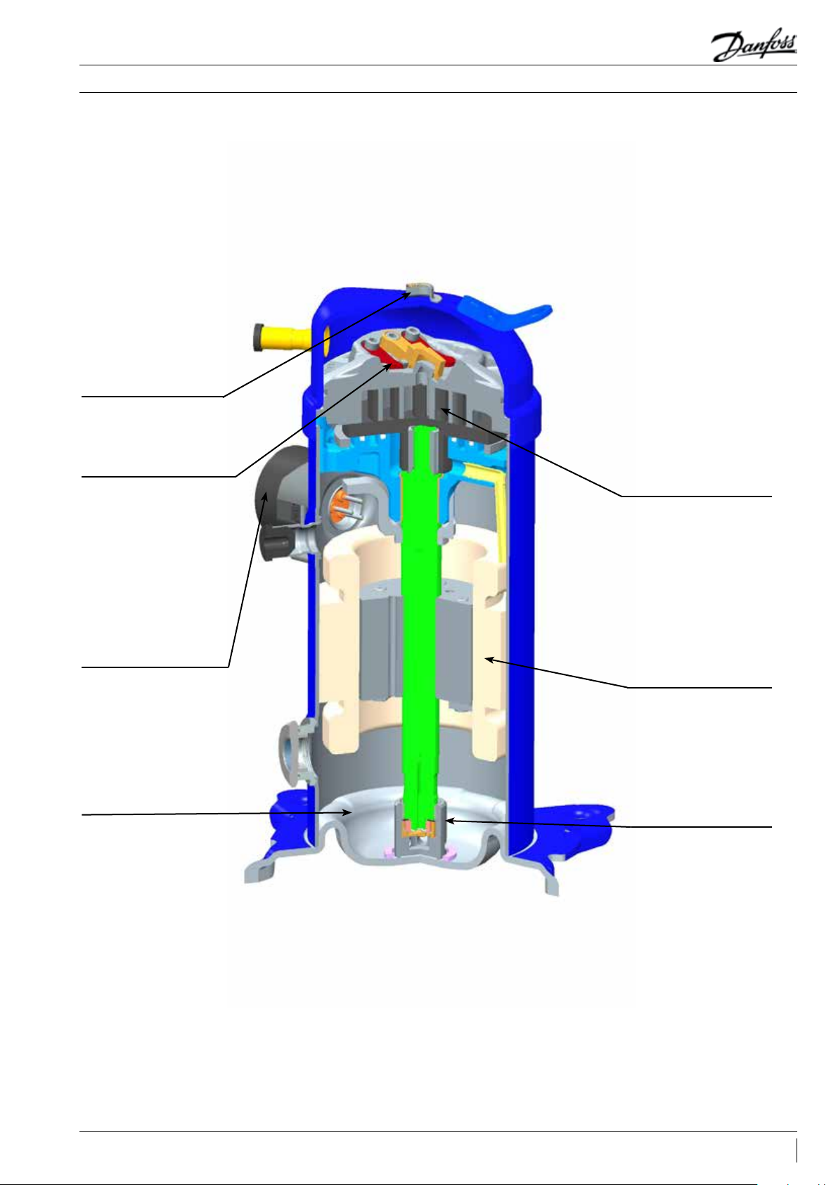
Discharge sensor (dome
sensor) for high discharge
temperature monitoring,
sensor is fitted into top
bracket. Discharge sensor
is optional.
Intermediate discharge
valves for better efficiency
at low pressure-ratio
VZH scroll specificities
Single compressors
Scrolls with optimized
volume ratio lead to better
heat pump application
EMC (Electro-Magnetic
Compatibility) bracket
provided allows for
grounding termination
of shielded wire-harness,
which reduces EMC
emissions between drive
and compressor
PVE 32 lubricant
New distributed IPM
motor lead to higher
power factor
Linear control oil pump
5AB225886435375en-001201
Page 6

Application Guidelines
Inverter compressors
Single compressors
Compressor size
Frequency converter variants
Inverter technology offers more flexibility
in compressor selection than fixed-speed
compressors. Selection of the right inverter
compressor size can be made by different
methods:
1. Maximum cooling capacity: Select a
compressor size which achieves the peak load
system cooling capacity demand at its maximum
speed.
2. Nominal cooling capacity: Select a compressor
size which achieves the nominal system cooling
capacity at a rotational speed of 3600 - 4500 rpm
(60-75 rps).
Different frequency converter variants are
available according to:
Frequency converter for VZH028-035-044
200V&400V: CDS803
1. Mains supply voltage:
- 200-240V/3ph/50-60Hz
- 380-480V/3ph/50-60Hz
2. IP class (CDS803 drives are available in IP20 or
IP21 (requiring additional kit) housings)
3. Best Seasonal Efficiency Ratio: Select a
compressor size which achieves the minimum
system cooling demand at its minimum speed.
Ensure that the compressor is able to cover the
peak load system cooling capacity. This selection
makes the compressor run for a maximum time at
part load where the system efficiency is highest.
Performance tables at three speeds can be found
in the following pages. Detailed performances
can be found in datasheets and in selection
programs.
3. RFI (Radio Frequency Interference) class H4
4. Printed Circuit Board (PCB) coated
Frequency converter for VZH028-035-044 575V:
CDS303
1. Mains supply voltage: 525-600V/3ph/50-60Hz
2. IP class: IP20
3. RFI class HX: No filter
4. PCB not coated
Compressor and frequency converter combinations
VLT Compressor Drives literatures
When the compressor size and mains voltage
have been defined in the above selection criteria,
the code number tables from the “Ordering
information and packaging” section provides the
appropriate frequency converter sizes and up
to eight corresponding code numbers for each
compressor model.
VLT Compressor Drives User’s Manual
(FRCC.ES.017.A1.02) introduces different VLT
Note this compressor is equipped with
a four-pole electrical motor so the applied
frequency from the inverter will be 30 Hz
for 15 rps (900 rpm) up to 200 Hz for 100 rps
(6000 rpm).
Please refer to the table below
min max
Compressor speed
Drive output frequency Hz 30 200
Compressor Drives literatures: Operating
instructions, MCT 10 set-up, Modbus RTU
instructions, VLT drawings, etc..
rps 15 100
rpm 900 6000
6 AB225886435375en-001201
Page 7
Application Guidelines
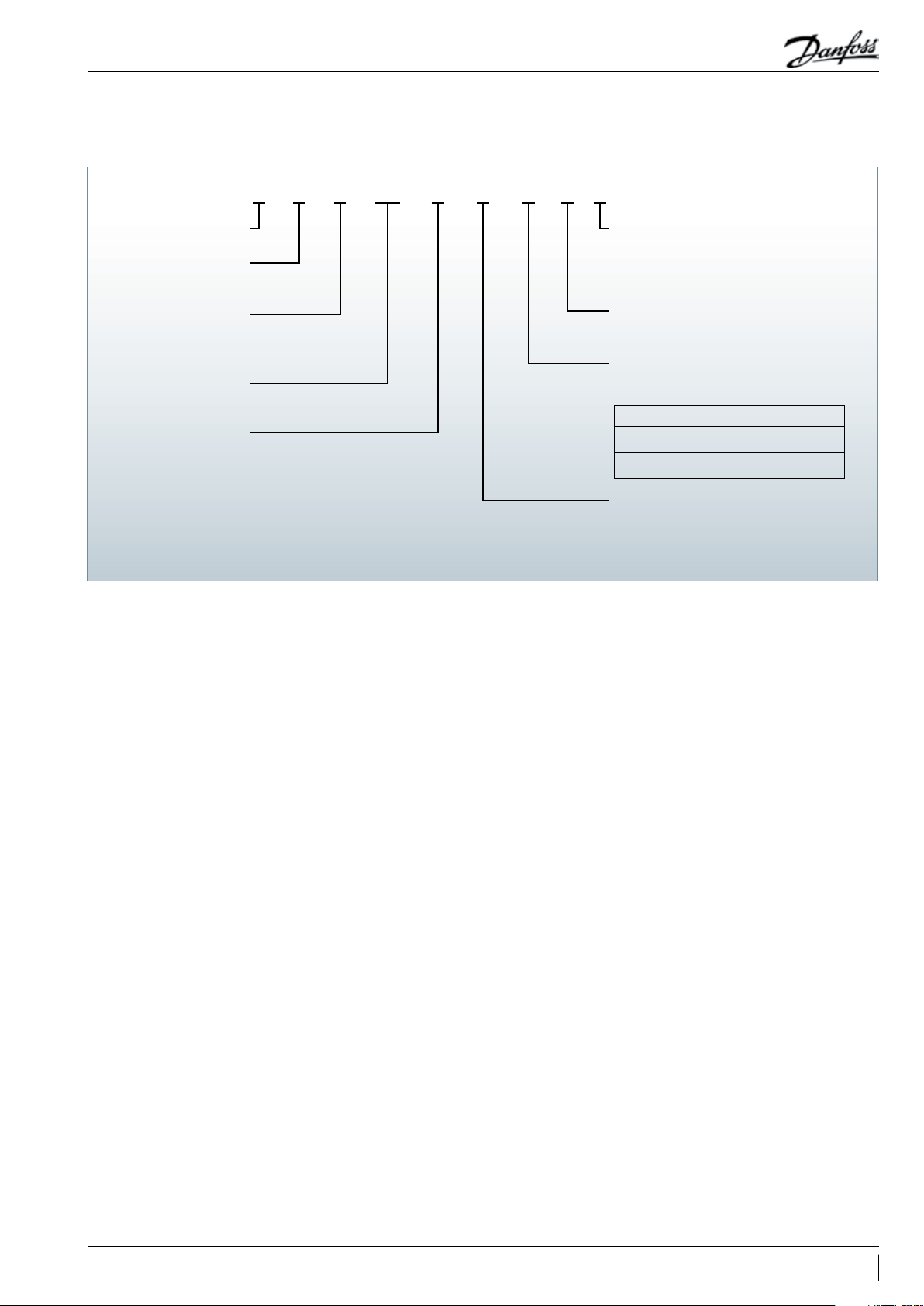
Compressor
nomenclature
Nomenclature and specifications
Single compressors
BNAGC044ZHV
Variable speed
Family
VZH scroll
Lubricant
PVE 32 (160 HV) lubricant,
R410A refrigerant
Swept volume
in cm³/rev
Design pressure ratio
C: IDV and IEER
optimized
Evolution index:
B : Max. evaporating temperature 27(°C)
on operation map
Motor protection type
N: no internal motor protection
(protection by drive)
Equipement version
A: brazed connections, OSG version
B: brazed connections, OLS version
Oil level switch
None
Threaded
OSG (oil sight glass)
version
OLS (oil level sensor)
version
Oil sight glass
Threaded
None
Motor voltage code to CDS803/CDS303 *
G: 380-480V/3~/50 & 60 Hz
H: 525-600V/3~/50&60Hz
J: 200-240V/3~/50 & 60 Hz
* main supply voltage to frequency converter
7AB225886435375en-001201
Page 8
A 1234567825
B
Application Guidelines
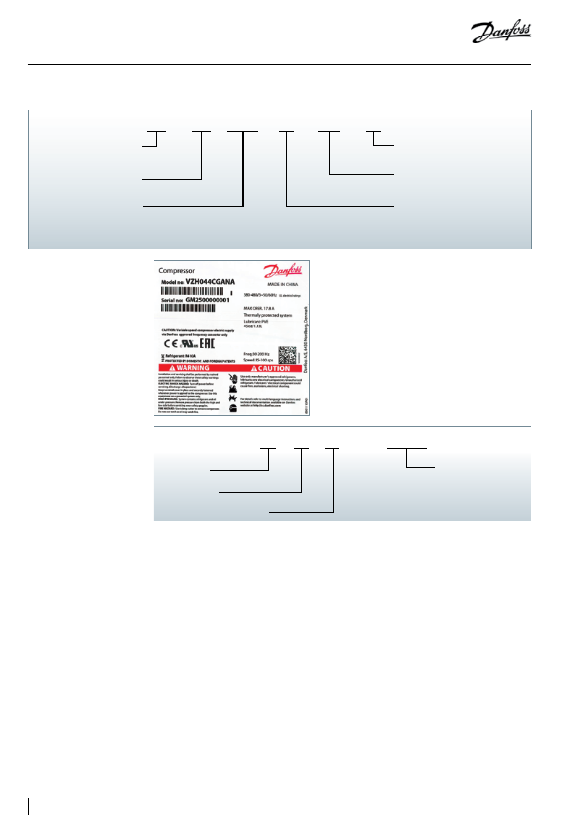
Frequency converter nomenclature
Nomenclature and specifications
Single compressors
H4E20T4P7K5803CDS
Dedicated compressor
drive for VZH scroll
Serie 803/303
output power
P6K0/P7K5/P10K/P11K
Label
in kW
RFI clas
H4/HX
Enclosure protection
IP rating
Main supply voltage
T2: 200-240V/3 ph/50-60 Hz
T4: 380-480V/3 ph/50-60 Hz
T6: 525-600V/3ph/50-60 Hz
Serial number
Year code
Month code
Plant assembly line code
8 Digit serial number
8 AB225886435375en-001201
Page 9

Application Guidelines
Technical specifications
Single compressors
Compressor
specifications
Frequency converter
specifications
Compressor model
VZH028 27. 8 1.5 5.0 6.0 10.0 1.3 26
VZH035 34.9 1.9 6.3 7.5 12.6 1.3 27
VZH044 44.5 2.4 8.0 9.6 16. 0 1.3 27
Mains supply voltage
Supply frequency 50 / 60 Hz
Output voltage 0 - 100 % of supply voltage
Standby power
Inputs
Programmable outputs
Protection functions Over-current protection, low / high current handling
Compressor functions
Swept
volume
(cm³/r ev)
15 rps
(m³/h)
CDS803-T2: 200 - 240 V +/-10% (3-phase)
CDS803-T4: 380 - 480 V +/-10% (3-phase)
CDS303-T6: 525 - 600V +/-10% (3-phase)
T2: P6K0/P7K5: 23.17W P10K: 26.23W
T4: P6K0/P7K5: 11.3W P10K: 25.5W
T6: P7K5: 17W P11K: 29kW
CDS803: 4 digital (0 - 24 V), 2 analog (0 /±10 V or 4 - 20 mA, scalable)
CDS303: 6 digital (0-24V), 2 analog (0/+-10V or 4-20mA, scalable)
CDS803: 2 digital (0- 24 V), 2 analog (0-24 V), 2 relay
CDS303: 2 digital(0-24V), 1 analogue(0-24V), 2 relay
Pressostat / thermostat function (CDS303 only), short cycle protection, oil
return management
Displacement
50 rps
(m³/h)
60 rps
(m³/h)
100 rps
(m³/h)
Oil charge
(Liters)
Net weight
(kg)
Oil return management
Bearings lubrication
Oil return management function only works
under auto mode: After running at low rpm
(less than 40 rps) for 120 minutes, the internal
lubrication algorithm in the drive will accelerate
the compressor speed to 60 rps or above for
60 seconds to ensure sufficient lubrication of
compressor moving parts.
Warning:
This function is enabled by parameter 28-10 as
default setting. Please notice when hands on
mode is selected, oil return management will
A specific oil pump ensures optimal bearing
lubrication at all compressor speeds. The specific
oil pump provides sufficient bearing lubrication
not work even if parameter 28-10 (oil return
management) is set to on. If compressors run
below 40 rps for more than 120 minutes, oil
return fault alarm (A208) will report on LCP
and stop the compressor. Please select hands
on mode carefully and only select hands
on mode if the OEM has implemented oil
return management in the system controller
and qualified oil management. Under such
conditions, the compressor could run below 40
rps continually and meanwhile disable drive oil
return management 28-10.
at low speeds as well as to avoid excessive Oil
Circulation Ratio (OCR) at high speeds.
9AB225886435375en-001201
Page 10

Application Guidelines
Technical specifications
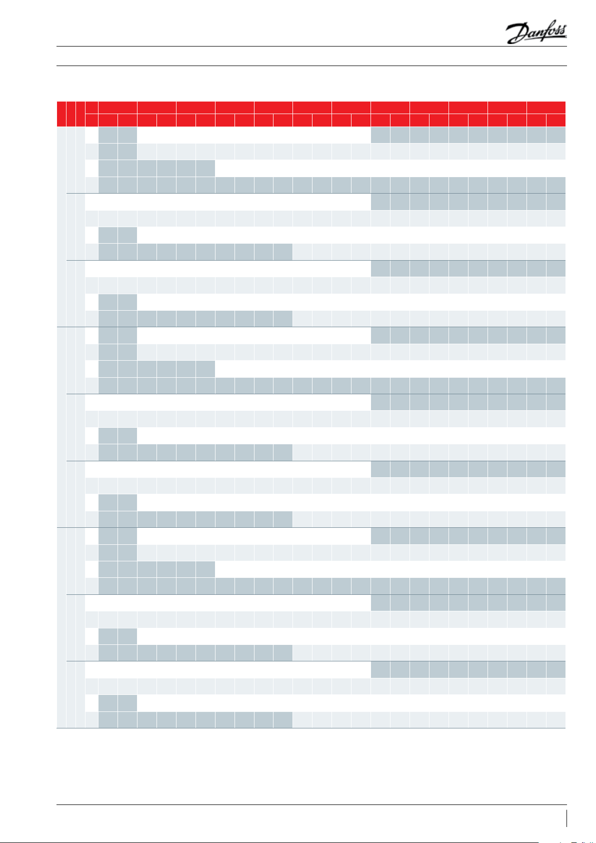
Capacity at EN12900 conditions - VZH028CJ-VZH035CJ-VZH044CJ
Te -30 -25 -20 -15 -10 -5 0 5 10 15 20 25
rps
rpm
Tc Qo Pe Qo Pe Qo Pe Qo Pe Qo Pe Qo Pe Qo Pe Qo Pe Qo Pe Qo Pe Qo Pe Qo Pe
Models
5 - - 185 0 0.538 2310 0.525 2860 0.491 3500 0.431 4240 0.340 5100 0. 213 - - - - - - - - - -
25 - - 14 60 0.773 1870 0.797 2350 0 .812 2910 0. 815 3550 0.799 4300 0.76 0 5140 0. 692 6100 0.591 718 0 0.452 8400 0.268 - -
30
180 0
45 - - - - - - 173 0 1.189 2180 1. 221 2710 1. 247 3310 1.262 4000 1.262 4790 1.241 5690 1.19 4 670 0 1.115 - -
65 - - - - - - - - - - - - - - - - - - - - - - - -
5 3010 1.038 3790 1.053 4730 1.039 5840 0.982 7150 0.867 8680 0.678 104 40 0.402 - - - - - - - - - -
25 2370 1.489 3050 1. 524 3860 1. 569 4820 1.60 9 5930 1.630 7230 1. 618 8730 1.557 10 450 1.433 12400 1.2 32 14600 0.938 1708 0 0.537 - -
60
3600
45 - - 2280 2.290 2940 2.287 3700 2.318 4600 2.369 5640 2 .426 6850 2.473 8240 2.496 9830 2.482 116 40 2. 414 1368 0 2.278 1598 0 2.060
VZH028CJ
65 - - - - - - - - - - 3760 3.558 4 620 3. 607 5630 3.671 6790 3.736 8130 3.786 9660 3.809 - -
5 5030 1.941 6300 1.9 86 7830 1.976 9650 1.898 117 80 1.739 142 60 1.484 17120 1.12 0 - - - - - - - - - -
25 4000 2.614 515 0 2.744 6500 2.858 8080 2 .942 9920 2.982 120 60 2.964 145 20 2. 876 173 40 2.702 20540 2.4 31 2415 0 2.048 28210 1. 539 - -
100
6000
45 - - 3860 3.806 4980 3.929 6280 4.059 7790 4.183 9540 4.288 11560 4.359 138 80 4.384 16530 4.349 1953 0 4.240 22930 4.043 26730 3.74 6
65 - - - - - - - - - - 6 430 6.008 7910 6.125 9640 6. 233 116 20 6 .319 13890 6.369 16480 6. 370 - -
5 - - 2340 0.655 2930 0.638 3620 0.597 4430 0.524 5370 0.414 6460 0. 261 - - - - - - - - - -
25 - - 1850 0.940 2370 0.969 2970 0.988 3680 0.990 4500 0.971 5440 0.924 6 510 0.8 42 7720 0.719 9090 0.550 10630 0. 329 -
30
180 0
45 - - - - - - 2190 1.4 46 2770 1.48 4 3430 1. 516 419 0 1. 534 5070 1.534 6070 1.508 7200 1.450 8480 1. 355
65 - - - - - - - - - - - - - - - - - - - - - - - -
5 3810 1.238 479 0 1.25 6 5980 1.240 7390 1.172 9050 1.034 10980 0.809 13210 0.480 - - - - - - - - - -
25 3000 1.776 3870 1. 818 4890 1.872 6100 1.92 0 7510 1.945 9160 1.930 11 050 1.858 13 220 1.710 15 690 1.4 69 1849 0 1.119 21620 0. 641 - -
60
3600
45 - - 2890 2.733 3720 2.728 4690 2.76 6 5820 2.827 714 0 2.894 8670 2.951 10 430 2.979 124 40 2 .961 1473 0 2.880 17320 2.718 20230 2.458
VZH035CJ
65 - - - - - - - - - - 4760 4.246 5850 4.304 712 0 4.380 8600 4.457 10290 4.518 122 30 4.544 - -
5 6360 2.320 7980 2 .374 9920 2. 363 12220 2.270 14920 2 .079 18060 1. 774 21670 1. 339 - - - - - - - - - -
25 5070 3.125 6520 3. 281 8220 3.417 10220 3 .517 12 560 3.565 152 60 3.54 4 18380 3.438 21950 3 .231 26000 2.907 30570 2.448 35710 1.8 40 - -
100
6000
45 - - 4890 4.551 6300 4.697 7950 4.853 9860 5. 001 120 80 5.127 14 630 5. 212 1757 0 5. 242 20920 5.200 24730 5.070 29020 4.835 3384 0 4. 479
65 - - - - - - - - - - 8140 7.18 4 10020 7.323 122 00 7.453 14710 7. 556 17580 7.615 20860 7. 616 - -
5 - - 3010 0.822 3760 0 .801 4650 0. 749 570 0 0.658 6910 0.520 8300 0.327 - - - - - - - - - -
25 - - 2380 1.180 3040 1.216 3820 1.24 0 4730 1.243 5780 1.219 6990 1.159 8370 1.057 9930 0.903 11 690 0.691 13670 0 .412 - -
30
180 0
45 - - - - - - 2820 1. 815 3560 1.863 4410 1.903 5390 1.926 6520 1.925 7810 1.893 9260 1. 820 10910 1.701
65 - - - - - - - - - - - - - - - - - - - - - - - -
5 4900 1.555 617 0 1. 578 7690 1.558 9510 1.472 11 64 0 1. 299 14120 1.016 16990 0.602 - - - - - - - - - -
25 3860 2. 231 4970 2.283 6290 2 .351 7840 2 .411 9660 2.4 43 11770 2.424 14210 2.333 17000 2.147 20180 1.845
60
3600
45 - - 3720 3.432 4780 3 .427 6030 3.473 7480 3.550 9180 3.635 1114 0 3.706 13410 3.741 16000 3 .719 18 940 3. 617 22270 3.414 26 020 3.087
VZH044CJ
65 - - - - - - - - - - 6120 5.332 753 0 5.405 9160 5. 501 11 050 5.598 13240 5. 674 15730 5.707 - -
5 8180 2.903 10260 2.970 1275 0 2.956 15710 2.839 19180 2.601 23220 2. 219 27870 1.675 - - - - - - - - - -
25 6520 3.910 8380 4.105 10570 4. 275 13150 4.400 16150 4.460 19 630 4.434 23640 4. 301 28220 4.0 42 33430 3.636 39320 3.063 45920 2.302 - -
100
6000
45 - - 6280 5.693 8100 5.876 10220 6.071 126 80 6.257 1553 0 6 .413 1882 0 6.520 2260 0 6.558 26910 6.505 31800 6.342 37320 6.048 43520 5.603
65 - - - - - - - - - - 10460 8.987 128 80 9.16 2 15680 9.323 18910 9.452 2 2610 9. 527 26830 9.527 - -
Single compressors
-
23770 1.405 27810 0.805 - -
To: Evaporating temperature in °C Superheat = 10 K
Tc: Condensing temperature in °C Subcooling = 0 K
Qo: Cooling capacity in W Pe: Power input in kW (with drive loss)
Note: All performance test data after run-in 72hr
10 AB225886435375en-001201
Page 11

Application Guidelines
Technical specifications
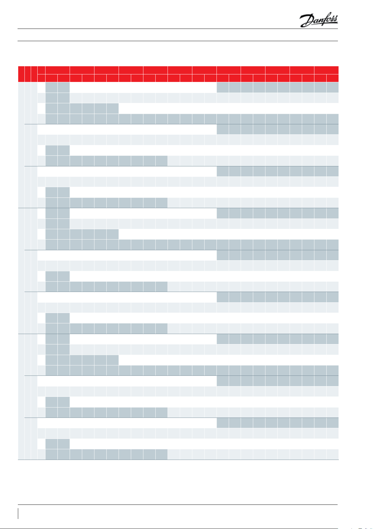
Capacity at ARI conditions - VZH028CJ-VZH035CJ-VZH044CJ
Te -30 -25 -20 -15 -10 -5 0 5 10 15 20 25
rps
rpm
Tc Qo Pe Qo Pe Qo Pe Qo Pe Qo Pe Qo Pe Qo Pe Qo Pe Qo Pe Qo Pe Qo Pe Qo Pe
Models
5 - - 1960 0.538 2440 0.525 3020 0.491 3690 0. 431 4480 0. 340 5380 0.213 - - - - - - - - - -
25 - - 1570 0.773 2010 0.797 2520 0. 812 3110 0. 815 3800 0.799 4590 0.760 5490 0.692 6520 0. 591 7670 0.452 8950 0.268 - -
30
180 0
45 - - - - - - 1910 1.189 2410 1.221 2980 1.247 3640 1.262 4390 1.262 5250 1. 241 6230 1.19 4 7330 1.115 - -
65 - - - - - - - - - - - - - - - - - - - - - - - -
5 3180 1.03 8 4000 1. 053 4990 1.039 617 0 0.982 7550 0.867 9150 0.678 11000 0.402 - - - - - - - - - -
25 2550 1.489 3280 1.524 4150 1. 569 516 0 1.6 09 6360 1. 630 7740 1.618 93 40 1.557 1116 0 1.433 13240 1. 232 15580 0.938 18220 0.537 - -
60
3600
45 - - 2530 2.290 3240 2.287 4080 2. 318 5060 2.369 6200 2.426 7520 2.473 9030 2.496 10770 2.482 1274 0 2 .414 14960 2. 278 1746 0 2.060
VZH028CJ
65 - - - - - - - - - - 4510 3.558 5520 3.607 6700 3.671 8070 3.736 9640 3.786 1143 0 3.809 - -
5 5320 1.941 6660 1.98 6 8280 1.976 10190 1. 898 1244 0 1.739 15 040 1.484 18040 1.120 - - - - - - - - - -
25 4300 2.614 5530 2 .744 6970 2. 858 8660 2.942 10620 2.982 12900 2.964 1553 0 2. 876 18520 2.702 21930 2.4 31 25770 2.048 30080 1.539 - -
100
6000
45 - - 4270 3.806 5500 3.929 6920 4.059 8580 4.183 1049 0 4.288 1270 0 4.359 15 230 4. 384 18110 4. 349 21380 4. 240 25070 4.0 43 2 9210 3. 746
65 - - - - - - - - - - 7700 6.008 9450 6.12 5 11470 6.233 13 800 6.319 16470 6.369 1950 0 6.370 - -
5 - - 2480 0.655 3090 0.638 3820 0 .597 4680 0.524 5670 0.414 6800 0. 261 - - - - - - - - - -
25 - - 19 90 0.9 40 2540 0.969 319 0 0.988 3940 0.990 4810 0.971 5810 0.924 6950 0.842 8250 0. 719 9700 0.550 113 30 0.329 -
30
180 0
45 - - - - - - 2420 1. 446 3040 1.48 4 3770 1.516 4600 1.534 5560 1.534 6650 1.50 8 7880 1. 450 9270 1.355
65 - - - - - - - - - - - - - - - - - - - - - - - -
5 4030 1.2 38 5070 1.256 6320 1.240 7810 1.172 9550 1.034 1158 0 0.809 1392 0 0.480 - - - - - - - - - -
25 3230 1.776 4150 1.818 5250 1.872 6540 1.920 8050 1.945 9800 1.930 1182 0 1. 858 14130 1.710 16760 1.4 69 197 20 1. 119 23060 0.641 - -
60
3600
45 - - 3200 2 .733 4110 2.728 5170 2. 766 6 410 2.827 7850 2.894 9520 2.951 114 40 2.979 13 630 2.961 1612 0 2.880 18940 2.718 22110 2.458
VZH035CJ
65 - - - - - - - - - - 5700 4. 246 6990 4. 304 8480 4.380 10210 4.457 12200 4 .518 14 470 4.544 - -
5 6730 2.320 8430 2.374 104 80 2.363 1290 0 2.270 1574 0 2.079 190 40 1.774 22840 1. 339 - - - - - - - - - -
25 5450 3.125 7000 3.281 8820 3.417 10960 3 .517 13 450 3.565 16330 3.544 19 650 3.438 23450 3. 231 27 760 2.907 32620 2.448 38080 1.840 - -
100
6000
45 - - 5400 4 .551 6960 4.697 8760 4.853 108 60 5.0 01 13280 5 .127 16070 5 .212 19270 5.242 22930 5.20 0 27070 5.070 3174 0 4.835 36980 4.479
65 - - - - - - - - - - 9740 7.18 4 11960 7. 32 3 14 520 7.453 174 70 7. 556 20840 7. 615 246 80 7. 616 - -
5 - - 318 0 0.822 3980 0.801 4910 0.749 6010 0.658 7290 0. 520 8750 0.327 - - - - - - - - - -
25 - - 2550 1.180 3270 1.216 4100 1. 240 5070 1.243 6190 1.219 74 80 1.159 8940 1.057 10610 0.903 124 80 0 .691 145 80 0.412 - -
30
180 0
45 - - - - - - 3110 1.815 3920 1.863 4850 1.90 3 5920 1.926 715 0 1.925 8550 1. 893 10140 1. 820 11930 1.701
65 - - - - - - - - - - - - - - - - - - - - - - - -
5 5180 1.555 6520 1. 578 8130 1.558 100 40 1.472 12 280 1.2 99 14900 1.016 17 900 0.602 - - - - - - - - - -
25 4150 2.231 5340 2.283 6750 2. 351 8 410 2. 411 1035 0 2.443 1260 0 2.424 152 00 2.333 18170 2 .147 21550 1. 845
60
3600
45 - - 4110 3.432 5280 3.427 6650 3.473 8240 3.550 1009 0 3.635 12 240 3.706 14710 3. 741 17 530 3.719 20730 3 .617 2436 0 3.414 28430 3.087
VZH044CJ
65 - - - - - - - - - - 7330 5. 332 8990 5.405 10910 5. 501 13130 5.598 15690 5 .674 18610 5.707 - -
5 8650 2.903 10 850 2.970 13470 2.956 16590 2.839 20240 2.601 24490 2. 219 29370 1.675 - - - - - - - - - -
25 7010 3.910 9000 4.105 113 40 4.275 140 90 4.400 173 00 4.460 21010 4.434 25280 4.301 30160 4.042 35700 3.636 41950 3.063 48970 2.302 - -
100
6000
45 - - 6950 5.693 8950 5.876 11 270 6.071 13960 6.257 170 80 6.413 20670 6.520 24790 6.558 29480 6.505 34 810 6.342 40820 6.048 4756 0 5.603
65 - - - - - - - - - - 12530 8.987 1538 0 9.162 186 80 9.323 22470 9.452 26800 9. 527 3174 0 9. 527 - -
To: Evaporating temperature in °C Superheat = 11.1 K
Tc: Condensing temperature in °C Subcooling = 8.3 K
Qo: Cooling capacity in W Pe: Power input in kW (with drive loss)
Rating point: ARI@60 rps
To/Tc/SH/SC: 7.2°C/54.4°C/11.1K/8.3K@60rps
Single compressors
-
25370 1.40 5 29650 0.805 - -
Note: All performance test data after run-in 72hr
11AB225886435375en-001201
Page 12

Application Guidelines
Technical specifications
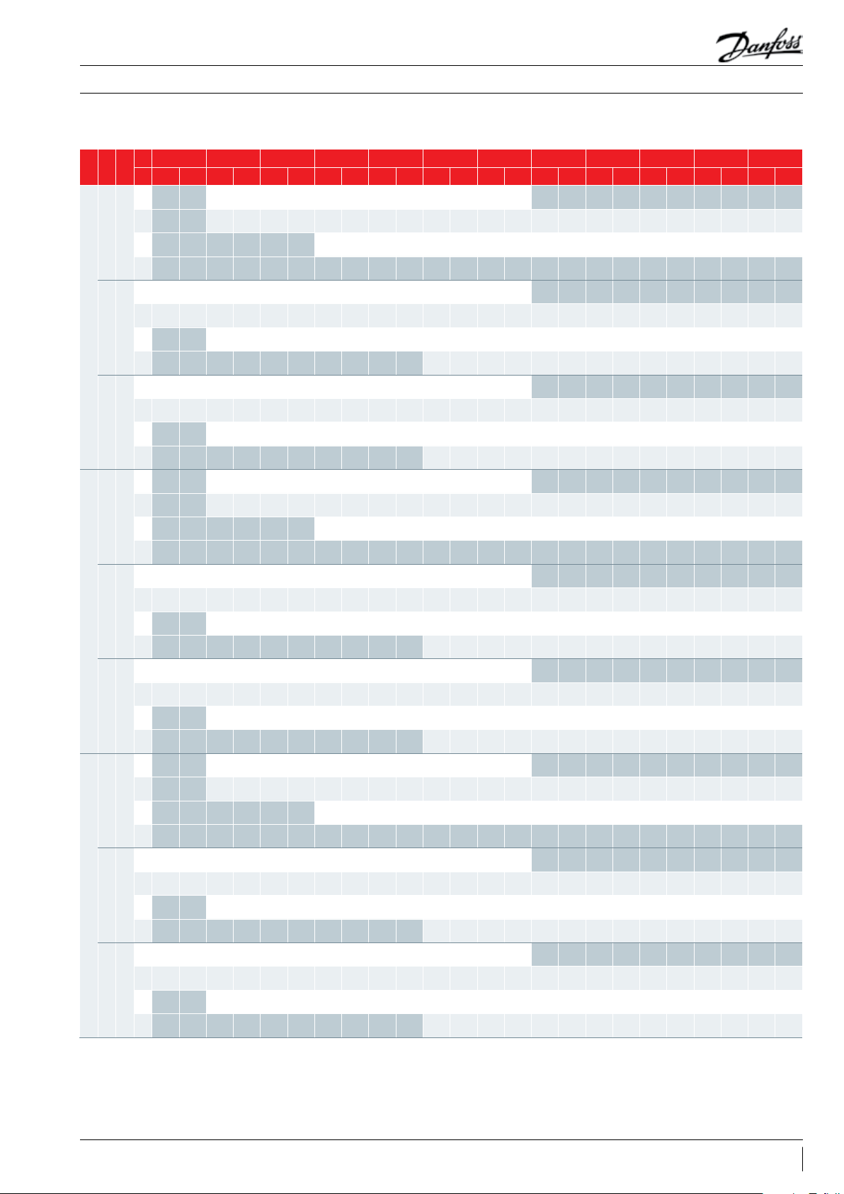
Capacity at EN12900 conditions - VZH028CH-VZH035CH-VZH044CH
Te -30 -25 -20 -15 -10 -5 0 5 10 15 20 25
rps
rpm
Tc Qo Pe Qo Pe Qo Pe Qo Pe Qo Pe Qo Pe Qo Pe Qo Pe Qo Pe Qo Pe Qo Pe Qo Pe
Models
5 - - 185 0 0.557 2310 0.543 2860 0. 508 3500 0.446 4240 0.353 5100 0.223 - - - - - - - - - -
25 - - 14 60 0.799 1870 0.823 2350 0.839 2910 0. 842 3550 0.825 4300 0.785 5140 0.716 6100 0 .612 7180 0.469 8400 0 .281 - -
30
180 0
45 - - - - - - 173 0 1. 228 218 0 1. 261 2710 1. 288 3310 1.303 4000 1. 303 4790 1. 280 5690 1.232 670 0 1.151 - -
65 - - - - - - - - - - - - - - - - - - - - - - - -
5 3010 1.037 3790 1.053 473 0 1.039 5840 0.982 715 0 0.866 8680 0.678 104 40 0.402 - - - - - - - - - -
25 2370 1.488 3050 1. 523 3860 1. 568 4820 1.60 8 5930 1.630 7230 1 .617 8730 1. 556 10 450 1.432 12 400 1. 231 14 600 0.938 1708 0 0.537 - -
60
3600
45 - - 2280 2.289 2940 2.286 370 0 2.317 4600 2.368 5640 2. 425 6850 2. 472 8240 2.496 9830 2. 481 116 40 2. 413 13 680 2.277 15980 2.059
VZH028CH
65 - - - - - - - - - - 3760 3.557 4 620 3.606 5630 3.670 6790 3.734 8130 3.785 9660 3. 807 - -
5 5030 1.894 630 0 1.938 7830 1.928 9650 1.852 1178 0 1.697 1426 0 1.44 8 1712 0 1.093 - - - - - - - - - -
25 4000 2.551 5150 2.678 6500 2.789 8080 2. 871 9 920 2.910 1206 0 2.893 14 520 2.806 1734 0 2.637 20540 2.372 24150 1.998 28210 1. 502 - -
100
6000
45 - - 3860 3.714 4980 3.834 6280 3.961 7790 4.082 9540 4.184 115 60 4.254 13880 4.279 1653 0 4.244 1953 0 4 .138 22930 3.946 26730 3.656
65 - - - - - - - - - - 6 430 5.863 7910 5.977 9640 6.083 116 20 6.167 13890 6 .216 16 480 6 .216 - -
5 - - 2340 0. 651 2930 0.634 3620 0. 593 4430 0. 520 5370 0. 411 6460 0. 258 - - - - - - - - - -
25 - - 1850 0.935 2370 0.963 2970 0.982 3680 0.984 4500 0.965 5440 0.918 6510 0. 836 7720 0.714 9090 0.546 10 630 0.325 -
30
180 0
45 - - - - - - 2190 1.438 2770 1. 476 3430 1.507 419 0 1.526 5070 1.525 6070 1.4 99 7200 1. 442 8480 1. 347
65 - - - - - - - - - - - - - - - - - - - - - - - -
5 3810 1.242 4790 1.26 0 5980 1.244 7390 1.175 9050 1.037 109 80 0 .811 13210 0.4 81 - - - - - - - - - -
25 3000 1. 781 3870 1.823 4890 1. 877 6100 1.925 7510 1.951 916 0 1.93 6 1105 0 1. 863 1322 0 1. 715 1569 0 1.474 18 490 1.122 21620 0.6 43 - -
60
3600
45 - - 2890 2. 740 3720 2.736 4690 2.773 5820 2.835 7140 2.902 8 670 2.959 10430 2.987 124 40 2.969 1473 0 2.888 17320 2.726 20230 2.465
VZH035CH
65 - - - - - - - - - - 4760 4.258 5850 4.316 7120 4.392 8600 4.470 10290 4.531 12 230 4.557 - -
5 6360 2.378 7980 2.433 9920 2.421 12220 2.326 1492 0 2 .130 18060 1. 818 21670 1. 372 - - - - - - - - - -
25 5070 3. 203 6520 3.363 8220 3.502 102 20 3.605 12560 3.653 152 60 3.632 183 80 3.523 2195 0 3 .3 11 26000 2.979 30570 2.509 35710 1.886 - -
100
6000
45 - - 4890 4.664 6300 4. 814 7950 4.973 9860 5 .125 120 80 5.254 14630 5 .341 17 570 5.372 20920 5.329 24730 5 .195 29020 4.954 33840 4.590
65 - - - - - - - - - - 8140 7. 36 2 10020 7.50 5 1220 0 7. 638 14710 7. 743 17580 7. 80 4 20860 7. 80 5 - -
5 - - 3010 0. 855 3760 0.833 4650 0.779 570 0 0.685 6910 0.542 8300 0.344 - - - - - - - - - -
25 - - 2380 1.226 3040 1.26 4 3820 1.288 4730 1.292 5780 1. 266 6990 1.204 8370 1.098 9930 0.939 1169 0 0.720 13670 0.433 - -
30
180 0
45 - - - - - - 2820 1.8 85 3560 1.935 4410 1.976 5390 2.000 6520 1.999 7810 1.964 9260 1. 889 10 910 1.765
65 - - - - - - - - - - - - - - - - - - - - - - - -
5 4900 1.573 6170 1. 596 7690 1.576 9510 1.489 116 40 1. 314 14120 1. 028 169 90 0.609 - - - - - - - - - -
25 3860 2.257 4970 2 .310 6290 2.378 7840 2.439 9660 2.471 11770 2.452 14210 2.360 17000 2.172 20180 1.867
60
3600
45 - - 3720 3.472 4780 3.467 6030 3. 514 74 80 3.592 9180 3.677 1114 0 3 .749 13410 3.785 16000 3.762 18940 3.659 22270 3.453 26020 3.123
VZH044CH
65 - - - - - - - - - - 6120 5.395 7530 5.468 916 0 5.565 110 50 5.663 13240 5 .740 157 30 5.7 74 - -
5 8180 2.896 10260 2.963 12750 2.949 15710 2 .832 1918 0 2.594 23220 2. 214 27870 1.671 - - - - - - - - - -
25 6520 3.900 8380 4.095 10570 4.265 13150 4.390 16150 4.449 196 30 4.423 23640 4. 291 28220 4.032 33430 3.627 39320 3.056 45920 2.297 - -
100
6000
45 - - 6280 5.679 810 0 5.862 10220 6.056 126 80 6. 241 15530 6.398 1882 0 6.505 22600 6.542 26910 6.489 318 00 6.327 37320 6.033 43520 5.589
65 - - - - - - - - - - 10460 8.965 128 80 9.13 9 15680 9. 301 18910 9.429 22610 9.504 26830 9.504 - -
Single compressors
-
23770 1.422 27810 0. 815 - -
To: Evaporating temperature in °C Superheat = 10 K
Tc: Condensing temperature in °C Subcooling = 0 K
Qo: Cooling capacity in W Pe: Power input in kW (with drive loss)
Note: All performance test data after run-in 72hr
12 AB225886435375en-001201
Page 13
Application Guidelines
Technical specifications
Capacity at ARI conditions - VZH028CH-VZH035CH-VZH044CH
Te -30 -25 -20 -15 -10 -5 0 5 10 15 20 25
rps
rpm
Tc Qo Pe Qo Pe Qo Pe Qo Pe Qo Pe Qo Pe Qo Pe Qo Pe Qo Pe Qo Pe Qo Pe Qo Pe
Models
5 - - 1960 0.557 2440 0.543 3020 0.508 3690 0.446 4480 0. 353 5380 0.223 - - - - - - - - - -
25 - - 1570 0.799 2010 0.823 2520 0.839 3110 0.842 3800 0.825 4590 0.785 5490 0.716 6520 0. 612 7670 0.469 8950 0. 281 - -
30
180 0
45 - - - - - - 1910 1.228 2410 1. 261 2980 1. 288 3640 1.30 3 4390 1. 303 5250 1.280 6230 1.232 7330 1.151 - -
65 - - - - - - - - - - - - - - - - - - - - - - - -
5 3180 1.037 4000 1.053 499 0 1. 039 6170 0.982 7550 0.866 9 150 0 .678 11000 0.402 - - - - - - - - - -
25 2550 1.488 3280 1.523 4150 1.568 5160 1.60 8 6360 1.630 7 740 1.617 9340 1. 556 1116 0 1.432 13240 1.231 15580 0.938 1822 0 0.537 - -
60
3600
45 - - 2530 2.289 3240 2.286 4080 2.317 5060 2.368 6200 2.42 5 7520 2 .472 9030 2.496 10770 2.481 1274 0 2. 413 14960 2.277 174 60 2.059
VZH028CH
65 - - - - - - - - - - 4510 3.557 5520 3.606 6700 3.670 8070 3.734 9640 3.785 1143 0 3. 807 - -
5 5320 1. 894 6660 1.938 8280 1.928 10190 1.852 12440 1.6 97 150 40 1.448 18040 1. 093 - - - - - - - - - -
25 4300 2 .551 553 0 2.678 6970 2.789 8660 2.871 10620 2 .910 1290 0 2.893 15530 2.806 18520 2.637 2193 0 2.372 25770 1.998 30080 1.5 02 - -
100
6000
45 - - 4270 3.714 5500 3.834 6920 3.9 61 8580 4.082 10 490 4 .184 12700 4.254 152 30 4.279 18 110 4.24 4 2138 0 4 .138 25070 3.94 6 2 9210 3.656
65 - - - - - - - - - - 7700 5.863 9450 5.977 11470 6.083 13 800 6 .167 16470 6.216 1950 0 6. 216 - -
5 - - 2480 0.651 3090 0.634 3820 0.593 4680 0.520 5670 0 .411 6800 0.258 - - - - - - - - - -
25 - - 19 90 0.935 2540 0.963 3190 0.982 3940 0.984 4810 0.965 5810 0.918 6950 0.836 8250 0.714 9700 0.546 113 30 0. 325 -
30
180 0
45 - - - - - - 2420 1.438 3040 1.476 3770 1.507 4600 1. 526 5560 1. 525 6650 1.499 7880 1.442 9270 1. 347
65 - - - - - - - - - - - - - - - - - - - - - - - -
5 4030 1.242 5070 1.2 60 6320 1.244 7810 1.175 9550 1.037 1158 0 0 .811 13920 0.4 81 - - - - - - - - - -
25 3230 1.781 4150 1. 823 5250 1.877 654 0 1.925 8050 1.951 9800 1.936 118 20 1. 863 14130 1.715 1676 0 1. 474 19 720 1.12 2 23060 0.6 43 - -
60
3600
45 - - 3200 2.74 0 4 110 2.736 5170 2.773 6 410 2. 835 7850 2.902 9520 2.959 11 44 0 2.987 136 30 2.969 1612 0 2.888 18940 2.726 2 2110 2.465
VZH035CH
65 - - - - - - - - - - 5700 4.258 6990 4. 316 8480 4.392 10210 4. 470 122 00 4 .531 14470 4.557 - -
5 6730 2 .378 8430 2.433 104 80 2.421 12 900 2.326 1574 0 2.13 0 190 40 1.818 22840 1. 372 - - - - - - - - - -
25 5450 3.203 7000 3.363 8820 3.502 10960 3.605 13450 3.653 16330 3.632 19650 3.523 23450 3 .311 27760 2.979 32620 2.509 38080 1.886 - -
100
6000
45 - - 5400 4.664 6960 4.814 8760 4.973 108 60 5 .125 13280 5.254 16 070 5.341 19270 5.372 22930 5. 329 27070 5.195 3174 0 4.954 36980 4.590
65 - - - - - - - - - - 9740 7.3 62 11960 7. 50 5 14 520 7.6 38 17470 7. 743 20840 7.80 4 24680 7. 80 5 - -
5 - - 318 0 0.855 3980 0.833 4910 0.779 6010 0.685 7290 0.542 8750 0.344 - - - - - - - - - -
25 - - 2550 1. 226 3270 1.26 4 410 0 1.2 88 5070 1.292 6190 1. 266 7480 1.20 4 8940 1.098 10610 0.939 12 480 0.720 14 580 0.433 - -
30
180 0
45 - - - - - - 3110 1.885 3920 1. 935 4850 1.976 5920 2.000 715 0 1.999 8550 1.964 1014 0 1.8 89 11 930 1.76 5
65 - - - - - - - - - - - - - - - - - - - - - - - -
5 5180 1.57 3 6520 1. 596 8130 1.576 10040 1.48 9 12280 1. 314 149 00 1. 028 17 900 0.609 - -
25 4150 2 .257 5340 2.310 6750 2.378 8410 2.439 10350 2. 471 12600 2.452 15200 2.360 1 8170 2 .172 21550 1. 867 25370 1.422 29650 0. 815 - -
60
3600
45 -
VZH044CH
65 - - - - - - - - - - 7330 5. 395 8990 5.468 10910 5.565 13130 5.663 15690 5 .740 18610 5.774 - -
5 8650 2.896 108 50 2.963 13470 2.949 1659 0 2.832 20240 2.594 24490 2.214 29370 1.671 - - - - - - - - - -
25 7010 3.900 9000 4.095 11 34 0 4.265 14090 4. 390 17 300 4.4 49 21010 4 .423 25280 4 .291 30160 4.032 35700 3.627 419 50 3.056 48970 2.297 - -
100
6000
45 - - 6950 5.679 8950 5.862 11270 6.056 13960 6. 241 1708 0 6.398 20670 6.505 24790 6.542 29480 6.489 34810 6.327 40820 6.033 47560 5.589
65 - - - - - - - - - - 12530 8.965 15 380 9.139 186 80 9. 301 22470 9.429 26800 9.504 31740 9.504 - -
To: Evaporating temperature in °C Superheat = 11.1 K
Tc: Condensing temperature in °C Subcooling = 8.3 K
Qo: Cooling capacity in W Pe: Power input in kW (with drive loss)
Rating point: ARI@60 rps
To/Tc/SH/SC: 7.2°C/54.4°C/11.1K/8.3K@60rps
- 4110 3.472 5280 3.467 6650 3.514 8240 3.592 10090 3.677 12240 3 .749 14710 3.785 175 30 3.762 20730 3. 659 24360 3.453 28430 3.12 3
Single compressors
-
Note: All performance test data after run-in 72hr
13AB225886435375en-001201
Page 14
Application Guidelines
Technical specifications
Capacity at EN12900 conditions - VZH028CG-VZH035CG-VZH044CG
Te -30 -25 -20 -15 -10 -5 0 5 10 15 20 25
rps
rpm
Tc Qo Pe Qo Pe Qo Pe Qo Pe Qo Pe Qo Pe Qo Pe Qo Pe Qo Pe Qo Pe Qo Pe Qo Pe
Models
5 - - 185 0 0.533 2310 0. 519 2860 0.486 3500 0.426 424 0 0.336 510 0 0 .211 - - - - - - - - - -
25 - - 14 60 0 .766 18 70 0.789 2350 0.804 2 910 0.807 3550 0.791 4300 0.752 514 0 0.686 6100 0.586 7180 0.4 47 8400 0.265 - -
30
180 0
45 - - - - - - 173 0 1.177 2180 1.208 2710 1. 234 3310 1.249 4000 1. 249 479 0 1.22 8 5690 1.18 2 670 0 1.10 4 - -
65 - - - - - - - - - - - - - - - - - - - - - - - -
5 3010 1.027 3790 1.043 473 0 1.029 5840 0.972 7150 0.858 8680 0.671 10440 0.398 - - - - - - - - - -
25 2370 1.474 3050 1. 509 3860 1.553 4820 1.593 5930 1.614 7230 1.602 8730 1. 541 10450 1.419 124 00 1.219 14600 0.929 170 80 0.532 - -
60
3600
45 - - 2280 2.268 2940 2. 264 370 0 2.295 4600 2.346 5640 2.402 6850 2.449 8240 2.472 9830 2 .457 116 40 2.390 136 80 2.255 15980 2.040
VZH028CG
65 - - - - - - - - - - 3760 3.523 4620 3.571 5630 3.635 6790 3.699 813 0 3 .749 9660 3.771 - -
5 5030 1.92 2 6300 1.966 7830 1.956 9650 1.879 11780 1.722 14260 1.4 69 17120 1.10 9 - - - - - - - - - -
25 4000 2.588 5150 2.717 6500 2.830 8080 2.913 9920 2.952 120 60 2 .935 14520 2. 847 173 40 2.676 20540 2.407 24150 2.028 28210 1.524 - -
100
6000
45 - - 3860 3.768 4980 3.890 6280 4 .018 7790 4 .141 9540 4.245 115 60 4. 316 138 80 4 .341 1653 0 4. 306 19530 4 .198 22930 4.003 26730 3.709
65 - - - - - - - - - - 6 430 5.9 49 7910 6.064 9640 6.172 1162 0 6. 257 13890 6.306 16 480 6. 307 - -
5 - - 2340 0.648 2930 0.632 3620 0.591 4430 0.519 5370 0 .410 6460 0.258 - - - - - - - - - -
25 - - 1850 0.9 31 2370 0.959 2970 0.978 3680 0.981 4500 0.962 5440 0. 914 6 510 0.833 7720 0.712 9090 0. 545 10 630 0.325 -
30
180 0
45 - - - - - - 2190 1.432 2770 1. 470 3430 1.501 419 0 1. 519 5070 1. 519 6070 1.4 93 7200 1. 436 8480 1.342
65 - - - - - - - - - - - - - - - - - - - - - - - -
5 3810 1.226 479 0 1. 244 5980 1.228 7390 1.160 9050 1. 024 109 80 0.8 01 13210 0.475 - - - - - - - - - -
25 3000 1. 759 3870 1.80 0 4890 1.853 610 0 1.901 7510 1.926 916 0 1 .911 11 050 1.839 13 220 1.693 15 690 1.455 18 490 1.108 21620 0.635 - -
60
3600
45 - - 2890 2.706 3720 2 .701 4690 2.738 5820 2.799 7140 2.865 8670 2.921 10430 2.949 12 440 2.932 14730 2.851 17320 2.691 20230 2.434
VZH035CG
65 - - - - - - - - - - 4760 4.204 5850 4.261 712 0 4. 337 8600 4. 413 1029 0 4.473 12230 4.499 - -
5 6360 2.297 7980 2. 351 9920 2.339 12220 2. 247 14920 2.058 18060 1.757 21670 1.326 - - - - - - - - - -
25 5070 3.094 6520 3. 249 8220 3.384 102 20 3.483 12560 3. 530 1526 0 3.509 183 80 3.404 219 50 3.199 26000 2.878 30570 2.424 35710 1. 822 - -
100
6000
45 - - 4890 4.506 6300 4.651 7950 4.805 9860 4.952 120 80 5.076 14630 5 .161 17570 5.190 20920 5 .148 24730 5.019 29020 4.787 3384 0 4.434
65 - - - - - - - - - - 8140 7.112 1002 0 7. 251 12 200 7. 37 9 14710 7. 48 1 17 580 7. 54 0 20860 7. 54 0 - -
5 - - 3010 0 .812 3760 0.791 4650 0.74 0 5700 0.650 6910 0 .513 8300 0.32 3 - - - - - - - - - -
25 - - 2380 1.166 3040 1. 201 3820 1.224 4730 1.22 8 5780 1. 204 6990 1.145 8370 1.043 9930 0. 891 116 90 0.682 13670 0.407 - -
30
180 0
45 - - - - - - 2820 1.792 3560 1.8 40 4 410 1. 879 5390 1.9 02 6520 1.901 7810 1.869 9260 1.798 10910 1.6 80
65 - - - - - - - - - - - - - - - - - - - - - - - -
5 4900 1.5 40 6170 1.5 62 7690 1.542 9510 1.457 1164 0 1.28 6 1412 0 1.006 1699 0 0.596 - - - - - - - - - -
25 3860 2.209 4970 2. 261 6290 2.327 7840 2.387 9660 2 .419 117 70 2.400 14210 2.310 17000 2 .126 20180 1. 827
60
3600
45 - - 3720 3.398 478 0 3.393 6030 3.439 7480 3. 515 9180 3.599 1114 0 3.669 13410 3.704 16000 3.682 1894 0 3.581 22270 3.380 26020 3.056
VZH044CG
65 - - - - - - - - - - 6120 5. 280 7530 5.352 9160 5. 447 11 050 5.543 13240 5.618 1573 0 5.651 - -
5 8180 2.897 10260 2.964 12 750 2.950 15710 2.834 19180 2.596 23220 2.215 27870 1.672 - - - - - - - - - -
25 6520 3.902 8380 4.097 10570 4. 267 13150 4.392 16150 4.4 51 1963 0 4.425 23640 4.293 28220 4.034 33430 3.629 39320 3.057 45920 2.298 - -
100
6000
45 - - 6280 5.682 8100 5. 865 10220 6.059 126 80 6. 244 1553 0 6. 401 18820 6.508 2260 0 6.545 26910 6.492 3180 0 6.329 37320 6.036 43520 5.592
65 - - - - - - - - - - 10460 8.969 128 80 9.143 15680 9.305 18910 9. 433 22610 9.508 26830 9. 509 - -
Single compressors
-
23770 1.391 27810 0.797 - -
To: Evaporating temperature in °C Superheat = 10 K
Tc: Condensing temperature in °C Subcooling = 0 K
Qo: Cooling capacity in W Pe: Power input in kW (with drive loss)
Note: All performance test data after run-in 72hr
14 AB225886435375en-001201
Page 15
Application Guidelines
Technical specifications
Capacity at ARI conditions - VZH028CG-VZH035CG-VZH044CG
Te -30 -25 -20 -15 -10 -5 0 5 10 15 20 25
rps
rpm
Models
VZH028CG
VZH035CG
VZH044CG
To: Evaporating temperature in °C Superheat = 11.1 K
Tc: Condensing temperature in °C Subcooling = 8.3 K
Qo: Cooling capacity in W Pe: Power input in kW (with drive loss)
Rating point: ARI@60 rps
To/Tc/SH/SC: 7.2°C/54.4°C/11.1K/8.3K@60rps
Tc Qo Pe Qo Pe Qo Pe Qo Pe Qo Pe Qo Pe Qo Pe Qo Pe Qo Pe Qo Pe Qo Pe Qo Pe
5 - - 1960 0.533 2440 0 .519 3020 0.486 3690 0. 426 4480 0.336 5380 0. 211 - - - - - - - - - -
25 - - 1570 0.766 2010 0.789 2520 0.804 3110 0.807 3800 0.791 4590 0.752 5490 0.686 6520 0.586 7670 0.447 8950 0.265 - -
30
180 0
45 - - - - - - 1910 1.17 7 2410 1. 208 2980 1.234 3640 1.249 4390 1. 249 5250 1. 228 6230 1.182 7330 1.10 4 - -
65 - - - - - - - - - - - - - - - - - - - - - - - -
5 3180 1.027 4000 1.043 4990 1.029 6170 0.972 7550 0.858 9150 0.671 11000 0. 398 - - - - - - - - - -
25 2550 1.474 3280 1.509 415 0 1.553 516 0 1.593 6360 1. 614 774 0 1.602 9340 1. 541 1116 0 1. 419 13240 1.219 1558 0 0.929 182 20 0.532 - -
60
3600
45 - - 2530 2.268 3240 2.264 4080 2.295 5060 2.346 6200 2.4 02 7520 2.449 9030 2 .472 10770 2.457 12 740 2.390 14960 2.255 174 60 2.040
65 - - - - - - - - - 4510 3.523 5520 3.571 670 0 3.635 8 070 3.699 9640 3.749 11430 3.771 - -
5 5320 1.92 2 6660 1.96 6 8280 1.956 10190 1.879 124 40 1. 722 150 40 1.4 69 18 040 1.109 - - - - - - - - - -
25 4300 2.588 5530 2 .717 6970 2.830 8660 2 .913 10 620 2.952 129 00 2 .935 15530 2.8 47 18520 2.676 219 30 2.407 25770 2.028 30080 1. 524 - -
100
6000
45 - - 4270 3.768 550 0 3.890 6920 4 .018 8580 4 .141 10490 4.245 1270 0 4. 316 1523 0 4.341 18 110 4.306 21380 4.198 25070 4.003 29210 3.709
65 - - - - - - - - - - 7700 5.949 9450 6.064 11 470 6.17 2 138 00 6.257 16470 6.306 195 00 6.307 - -
5 - - 248 0 0.648 3090 0.632 3820 0.591 4680 0. 519 5670 0.410 6800 0.258 - - - - - - - - - -
25 - - 19 90 0 .931 2540 0.959 3190 0.978 3940 0.981 4810 0.962 5810 0.914 6950 0. 833 8250 0 .712 9700 0.545 113 30 0.325 - -
30
180 0
45 - - - - - - 2420 1.432 3040 1.470 3770 1.501 4600 1. 519 5560 1.519 6650 1.493 7880 1.436 9270 1.342
65 - - - - - - - - - - - - - - - - - - - - - - - -
5 4030 1. 226 5070 1. 244 6320 1. 228 7810 1.160 9550 1.024 1158 0 0. 801 13920 0 .475 - - - - - - - - - -
25 3230 1.759 4150 1. 800 5250 1.853 6540 1.901 8050 1.926 9800 1.911 1182 0 1.839 14130 1.693 16760 1. 455 19720 1.108 23060 0.635 - -
60
3600
45 - - 3200 2.706 4110 2 .701 517 0 2.738 6 410 2.799 7850 2.865 9520 2.921 114 40 2.949 13630 2.932 16120 2.851 18940 2.691 2 2110 2.434
65 - - - - - - - - - - 5700 4.20 4 6990 4 .261 8480 4.337 10210 4. 413 122 00 4. 473 14470 4.499 - -
5 6730 2.297 8430 2 .351 10480 2.339 1290 0 2 .247 1574 0 2.058 19 040 1.757 22840 1. 326 - - - - - - - - - -
25 5450 3.094 7000 3. 249 8820 3.384 10960 3.483 13450 3. 530 16330 3.509 19650 3.404 23450 3 .199 27760 2.878 32620 2. 424 38080 1.822 - -
100
6000
45 - - 5400 4.506 6960 4.651 8760 4.805 1086 0 4.952 1328 0 5.076 16070 5.161 19270 5.190 22930 5.14 8 27070 5 .019 31740 4.787 36980 4.434
65 - - - - - - - - - - 9740 7.112 11960 7.2 51 1452 0 7.379 1747 0 7. 481 20840 7. 54 0 24 680 7. 54 0 - -
5 - - 318 0 0.812 3980 0.791 4910 0.74 0 6010 0.650 7290 0 .513 8750 0.323 - - - - - - - - - -
25 - - 2550 1.16 6 3270 1.201 4100 1.224 5070 1.22 8 619 0 1.204 74 80 1.145 8940 1.043 10610 0.891 124 80 0.682 14580 0.407 - -
30
180 0
45 - - - - - - 3110 1.792 3920 1.840 4850 1.879 5920 1.902 7150 1.901 8550 1.869 10140 1.798 119 30 1.6 80
65 - - - - - - - - - - - - - - - - - - - - - - - -
5 5180 1. 540 6520 1. 562 8130 1.542 10 040 1.457 122 80 1. 286 1490 0 1. 006 179 00 0.596 - - - - - - - - - -
25 4150 2.209 5340 2 .261 6750 2.327 8410 2. 387 1035 0 2.419 126 00 2.400 15200 2 .310 18170 2.12 6 21550 1.827 25370
60
3600
45 - - 4110 3.398 5280 3. 393 6650 3.439 824 0 3 .515 10090 3. 599 12 240 3.669 14710 3.704 17 530 3.682 20730 3.581 24360 3.380 28430 3.056
65 - - - - - - - - - - 7330 5.280 8990 5.352 10910 5.447 13130 5.543 15 690 5.618 18 610 5.651 - -
5 8650 2. 897 10850 2.964 13 470 2.950 16590 2.834 20240 2. 596 24490 2. 215 29370 1.672 - - - - - - - - - -
25 7010 3.902 9000 4.097 1134 0 4. 267 14090 4.392 173 00 4 .451 21010 4.425 25280 4.293 3016 0 4.034 35700 3.629 41950 3.057 48970 2.298 - -
100
6000
45 - - 6950 5.682 8950 5.865 112 70 6.059 13960 6. 244 17 080 6.4 01 20670 6. 508 24790 6. 545 29480 6.492 34 810 6. 329 40820 6.036 47560 5.592
65 - - - - - - - - - - 12530 8.969 153 80 9.143 186 80 9. 305 22470 9.433 26800 9. 508 3174 0 9.509 - -
Single compressors
1.391 29650 0.797 - -
Note: All performance test data after run-in 72hr
15AB225886435375en-001201
Page 16
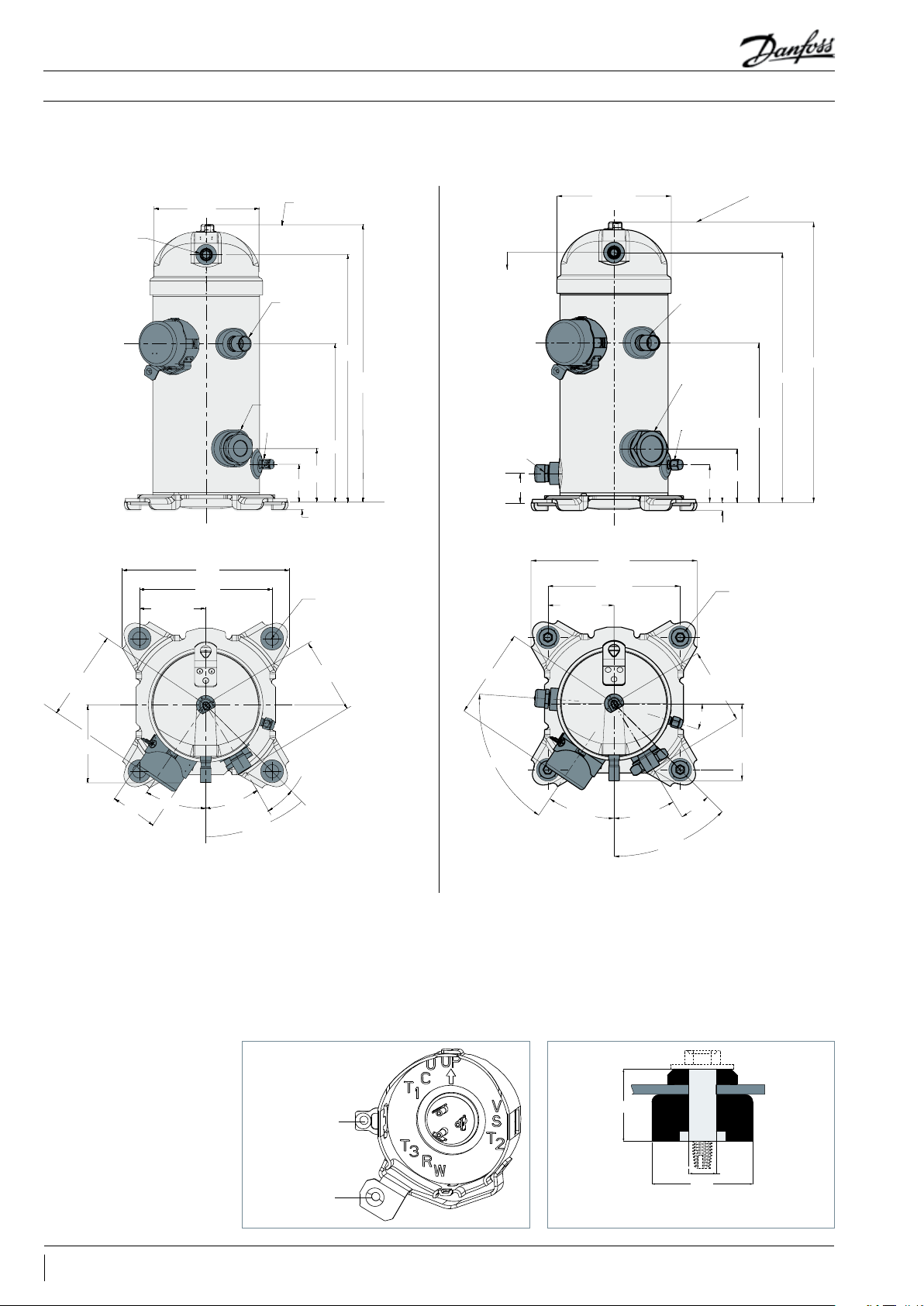
Overall height:
op of sensor bracket
Application Guidelines
Dimensions
Single compressors
VZH028-035-044G/J/H
OSG version
Ø164.5
Discharge line
1/2"
(95.25)
239
190.5
Top of sensor bracket
Suction
3/4"
Oil Sight Glass
1 1/8"
Schrader valve
and cover
55.0
78.0
11
230.5
Ø19.5
4X
360.4
404.4
VZH028-035-044G/J
OLS version
Discharge line
1/2"
Oil level sensor
prism
42.5
(95.25)
Ø164.5
239
190.5
Suction line
3/4"
Organ pipe
tting
Schrader valve
and cover
55.0
11
78.0
Ø19.5
4X
T
404.4
360.4
230.5
129.5
111.3
70.6
(34°) (31°)
109.7
14°±2°
45°±2°
129.5
(60°)
Terminal box (quick connect spade terminals)
109.7
Suction line
(17°)
discharge line
(34°)
(31°)
14°±2°
45°±2°
Note: Manifolding drawing is preliminary version
Mounting Grommet
111.3
All dimensions in mm
16 AB225886435375en-001201
Earth grounding
EMC bracket to
terminations of
shielded wire
29.5
Ø11
Ø 41
Recommended torque for
mounting bolts: 11 Nm (±1 Nm)
Page 17
Application Guidelines
Dimensions
Single compressors
Sight glass / Oil level sensor
VZH compressors OSG versions come equipped
with a threaded oil sight glass with 1"1/8 – 18
UNEF connection. It can be used for a visual
check of oil amount and condition.
Schrader
The oil fill connection and gauge port is a 1/4"
male flare connector incorporating a schrader
valve.
Suction & discharge connections
VZH compressors are all delivered with suction
and discharge brazed connections only. They are
copper-plated steel connections.
Rotolock adaptors are available, refer to the
“Accessories” section.
Compressor models Brazed connection size
VZH028-044
Suction 3/4" 1-1/4" 3/4"
Discharge 1/2" 1" 1/2" 120Z0365
VZH oil level sensor version compressors come
equipped with a screw-in optical part on oil level
switch port located below the electrical box.
Suction Discharge
VZH028-035-044 3/4" 1/2"
Rotolock adaptor set
(adaptor, gasket, sleeve, nut)
Rotolock Solder sleeve ODF Code Number Code Number
120Z0126
Rotolock adaptor
( adaptor only)
120Z0366
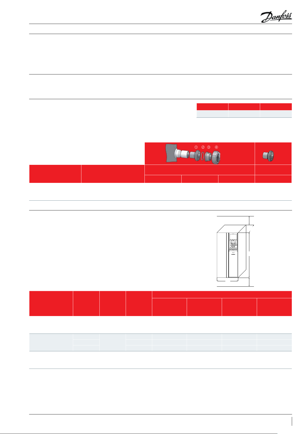
Frequency converter dimensions
Drive supply voltage
T2: 200-240/3/50-60
T4: 380-480/3/50-60
T6: 525-600/3/50 -60
Frequency converter dimensions depend
on supply voltage, IP rating and power. The
table below gives an overview of the overall
Min 100
Clearance above for cooling
L
dimensions and different drive enclosures
(H3, H4, H5, A3 and B3). Details for each drive
enclosure are on the following pages.
H
plate
Min 100
Clearance above for cooling
W
IP20
Drive power
kW
6
7.5 VZH035 H4 29 6x135x241 359x135x241 100/4
10 VZH044 H5 334x150x255 402 x150x255 100/4
6
7.5 VZH035 H3 255x100x206 329x100x206 100/4
10 VZH044 H4 296x135x241 359x135x241 100/4
7.5 VZH028 A3 268x13 0x2 05 374x130x205 100/4
11 H VZH035 B3 399x165x249 420x165x249 100/4
11 VZH044 B3 399x165x249 420x165x249 100/4
Compressor
voltage code
J
G
Compressor
model
VZH028 H4 29 6x135x241 359x135x241 100/4
VZH028 H3 255x100x206 329x100x206 100/4
Drive enclosure
Overall drive size
(H x W x L) mm
Overall drive size
(H x W x L) mm
incl. decoupling
Clearance above/
below
(mm/inch)
17AB225886435375en-001201
Page 18

Application Guidelines
CDS803 frequency converter
Dimensions
Single compressors
B
b
D
C
a
A
a
e
f
99 99
Decoupling Plate
e
Decoupling Plate Illustration
Enclosure Height (mm) Width (mm) Depth (mm) Mounting hole (mm) Max. Weight
Frame IP Class A A
1)
a B b C d e f kg
H3 IP20 255 329 240 10 0 74 206 11 5.5 8.1 4.5
H4 IP20 296 359 275 135 105 241 12.6 7 8.4 7.9
H5 IP20 334 402 314 150 12 0 255 12.6 7 8.5 9.5
1)
A
Including decoupling plate.
The dimensions are only for the physical units, but when installing in an application it is necessary to add space for free air passage both above and below the units. The amount
of space for free air passage is listed in “frequency converter dimensions - Clearance above/below (mm/inch)”.
CDS303 frequency converter
Enclosure Height (mm) Width (mm) Depth (mm) Mounting hole (mm) Max. Weight
Frame IP Class A A
1)
a B b C d e f kg
A3 IP20 268 374 257 130 110 205 11 5.5 9 6.6
B3 IP20 399 420 380 165 140 249 12 6.8 7.9 12
1)
A
Including decoupling plate.
The dimensions are only for the physical units, but when installing in an application it is necessary to add space for free air passage both above and below the units. The amount
of space for free air passage is listed in “frequency converter dimensions - Clearance above/below (mm/inch)”.
18 AB225886435375en-001201
Page 19

Application Guidelines
Electrical data, connections and wiring
Single compressors
Supply voltage
Compressor electrical
specifications
RLA (Rated Load Amp)
MOC (Max Operating
Current)
Because VZH compressors are powered by a
frequency converter, the mains frequency, 50 or
60 Hz, is no longer an issue. Only the mains
voltage is to be taken into account. With 3 motor
voltage codes, the most common mains voltages
and frequencies are covered. Never connect the
VZH compressor directly to the mains power
supply in the case motor burns out.
Compressor rated
voltage (V)
414 V max.
210 V max.
RW: Winding resistance per winding, measured at motor terminals
RLA: Rated load Amp
Model
VZH044CG /VZH044CH
VZH035CG /VZH035CH 12. 4 14.3
VZH028CG /VZH028CH 10.3 11. 8
VZH044CJ
VZH035CJ 26.6 30.6
VZH028CJ 22.0 25.3
RW(Ω) at 20°C line
Rated Load Amp value is the current value at
maximum load, in the operating envelope, and
Max operating current is the maximum
continuous current which is 115% (VZH044-J is
Voltage code Mains voltage range of drive
J
G
H
to line
0.708±7%
0.185±7 %
200-240 V / 3 ph / 50 Hz &
200-240 V / 3 ph / 60 Hz (±10%)
380-480 V / 3 ph / 50 Hz &
380-480 V / 3 ph / 60 Hz (±10%)
525-600 V / 3ph / 50Hz &
525-600 V /3ph / 60Hz (±10%)
RLA (A)
15. 5 17.8
33.3 36
Max Operating
Current (A)
at maximum speed and maximum drive input
voltage.
108%) of RLA. This value is printed on compressor
nameplate.
Wiring connections
VZH scroll compressors will only compress gas
while rotating counter-clockwise (when viewed
from the top of the compressor).
The drawing shows electrical terminal labeling
and should be used as a reference when wiring
the compressor.
U, V & W of the drive and the compressor must be
connected accordingly.
For use of EMC bracket with shielded cable, it is
recommended to have a thread cutting screw
(#10-32) having a torque of 3NM.
Terminal cover mounting The terminal cover and gasket should be installed
prior to operation of the compressor. The terminal
cover has two outside tabs, 180 degrees apart,
Terminal cover removal
push
Earth grounding
EMC bracket to
terminations of
shielded wire
that engage the terminal fence. When installing
the cover, check that it is not pinching the lead
wires.
push
push
19AB225886435375en-001201
Page 20

Application Guidelines
Electrical data, connections and wiring
Single compressors
Fuses
Danfoss recommends using the fuses listed
below to protect service personnel and property
in case of component break-down in the
frequency converter.
For circuit breakers, Moeller types have been
tested and are recommended. Other types of
circuit breakers may be used provided they limit
the energy to a level equal to or lower than the
Moeller types.
UL Compliant fuses Recommended circuit breaker
CDS 803
3x200-240 V IP20
4 TR/VZH028 FRS-R-50 KTN-R50 JKS-50 JJN-50 50 PKZM4-50
5 TR/VZH035 FRS-R-50 KTN-R50 JKS-50 JJN-50 50 PKZM4-50
6.5 TR/VZH044 FRS-R-60 KTN-R60 JKS-60 JJN-60 60 PKZM4-63
3x380-480 V IP20
4 TR/VZH028 FRS-R-25 KTS-R25 JKS-25 JJS -25 25 PK ZM4-25
5 TR/VZH035 FRS-R-25 KTS-R25 JKS-25 JJS -25 25 PK ZM4-25
6.5 TR/VZH044 FRS-R-30 KTS-R30 JKS-30 JJS-30 30 PKZM4-36
CDS 303
525-600V
CDS 303-7.5k W 20A gG KTS-R20 JKS-20 JJS-20 5017906 -020 KLSR020 A6K-20R PKZM4-50
CDS 303-11k W 30A gG KTS-R30 JKS-30 JJS-30 50179 06 -030 KLSR030 A6K-30R PKZM4-50
Bussmann Bussmann Bussmann Bussmann Max fuse
Type RK5 Type RK1 Type J Type T Typ e G Moeller type
EN 50178
Compliant fuses
Size Ty pe Type RK1 Type J Typ e T Type RK1 Type RK1 Type RK1 Moeller type
UL Non UL IP20
UL Compliant fuses
Bussmann SIBA Little fuse
Recommended
circuit breaker
20 AB225886435375en-001201
Page 21

Application Guidelines
Electrical data, connections and wiring
Single compressors
Wire sizes Below table lists recommended wiring sizes for the motor compressor power supply cables. These
wiring sizes are valid for a cable length up to 20m.
From network to frequency converter From frequency converter to compressor
Typ e mm² AWG Typ e mm² AWG
CDS803-6kW(IP20) 6 10 V ZH028 -J 6 10
200 - 240 V
380 - 400 V
525 - 600 V
Note: 1.The wire size here is the guideline but not the actual cable required. The required cable size should be specified by the OEM
depending on the unit design, ambient temperature, the wire material, current, etc.
CDS803-7.5kW(IP20) 6 10 VZH035-J 6 10
CDS803-10kW(IP20) 6 10 V ZH04 4-J 6 10
CDS803-6kW(IP20) 4 10 VZH028-G 4 10
CDS803-7.5kW(IP20) 4 10 VZH035-G 4 10
CDS803-10kW(IP20) 4 10 VZH044-G 4 10
CDS303-7.5kW(IP20) 4 10 VZH028-H 6 10
CDS303-11kW(IP20) 4 10 VZH035-H 6 10
CDS303-11kW(IP20) 4 10 VZH044-H 6 10
Wiring & EMC protection The motor compressor power supply from
the CDS803/303 frequency converter to the
VZH compressor must be done with a braided
screened/shielded cable. This cable needs to
have its screen/shielding conduit connected to
earth on both ends. Avoid terminating this cable
connection with twisting ends (pigtails) because
that would result in an antenna phenomenon
and decrease the effectiveness of the cable.
Control cables to the CDS803/303 frequency
converter must use the same installation
principles as the motor power supply cable.
The motor compressor cable must be installed in
a conduit separated from the control and mains
cables.
Physical installation of the frequency converter
on the mounting plate must ensure good
electrical contact between the mounting plate
and the metal chassis of the converter. Use starwashers and galvanically conductive installation
plates to secure good electrical connections.
Refer to instructions MG18N202/MG34M402 for
tightening torques and screw sizes.
Note that the CDS803/303 must be mounted on
a plain wall to ensure a good air flow through its
heat exchanger.
21AB225886435375en-001201
Page 22

Application Guidelines
Electrical data, connections and wiring
EMC correct installation of an IP20 frequency drive CDS803
EMC qualification reports are available upon request to Danfoss technical support.
Single compressors
Wiring diagram of CDS803
3 Phase
power
input
PLC etc.
PLC
Mains-supply
L1
L2
L3
PE
Reinforced protective earth
L1
L2
L3
PE
Min. 16 mm
Equalizing cable
Control cables
2
Min. 200 mm
between control
cable, mains cable
and between mains
motor cable
Panel
Com.
On
Warn.
Alarm
StatusQuick
Main
Menu
Menu
Menu
k
c
a
B
OK
Auto
Hand
Reset
On
On
Output
contactor etc.
Earthing rail
Cable insulation stripped
All cable entries in
one side of panel
Motor cable
Motor, 3 phases and
Protective earth
U
V
W
PE
Motor
22 AB225886435375en-001201
+10 V DC
0-10 V DC0/4-20 mA
0-10 V DC0/4-20 mA
50 (+10 V OUT)
53 (A IN)
54 (A IN)
55 (COM A IN/OUT)
42 0/4-20 mA A OUT / DIG OUT
45 0/4-20 mA A OUT / DIG OUT
12 (+24 V OUT)
18 (DIGI IN)
19 (DIGI IN)
20 (COM D IN)
27 (DIGI IN)
29 (DIGI IN)
24 V (NPN)
O V (PNP)
24 V (NPN)
O V (PNP)
24 V (NPN)
O V (PNP)
24 V (NPN)
O V (PNP)
Bus ter.
1 2
Bus ter.
RS-485
Interface
ON
ON=Terminated
OFF=Unterminated
(Com RS-485 ) 61
UDC-
UDC+
relay2
relay1
(N RS-485) 69
(P RS-485) 68
Not present on all power sizes
06
240 V AC 3 A
05
04
03
240 V AC 3 A
02
01
RS-485
Do not connect shield to 61
(PNP)-Source
(NPN)-Sink
Page 23

RELAY
2
CDS803
Application Guidelines
Electrical data, connections and wiring
Wiring connections of CDS803
L1 91 L1 U 96 T1/U
L2 92 L2 V 97 T2/V
L3 93 L3 W 98 T3/W
95 PE PE 99
45 0/4-20 mA A OUT / DIG OUT
42 0/4-20 mA A OUT / DIG OUT
50 +10 V OUT NC
53 A IN NO 02
54 A IN COM 01
55 COM A IN/OUT
12 +24 V OUT CO M 04
18 DIGI IN
19 DIGI IN
27 DIGI IN
29 DIGI IN
20 COM D IN
N RS-485 69
P RS-485 68
Com RS-485 61
1
03
RELAY
NC 06
NO 05
Single compressors
Legends:
A: Analog
DIGI: Digital
IN: Input
OUT: Output
COM: Common
NC: Normally-closed
NO: Normally-open
Open loop Process loop
91,92,93 3 phases mains input x x
95 Earth x x
42,45
0/4-20 mA Analague Output or Digital
Output
- -
50 +10V DC Output - 53 0-10V or 4-20mA Analague Input x 54 0-10V or 4-20mA Analague Input - x
55 Com Analague In/Out x 12 +24V output - 18 External On/Off(NO) x x
19 Digital Input - 27 Safety Device e.g.: HP/LP switch x x
29 Digital Input - 20 Com Digital Input - 98 To Compressor T3 x x
97 To Compressor T2 x x
96 To Compressor T1 x x
99 Earth x x
03,02,01 Relay 1 - -
06,05,04 Relay 2 - -
69,68 RS485 Bus - -
61 RS485 Bus Com - -
-: Optional connection
X: Mandatory connection
The CDS803 frequency converter is factory
preset with parameters for the open loop control
principle. The process loop control principle can
be selected by changing parameters in the “Quick
menu.”
Open loop: preset on input 53
0 - 10 V control
Frequency converter in slave mode
Process loop: preset on input 54
4 - 20 mA control
Frequency converter under own PID controller
23AB225886435375en-001201
Page 24

Application Guidelines
Electrical data, connections and wiring
EMC correct installation of an IP20 frequency drive CDS303
EMC qualification reports are available upon request to Danfoss technical support.
PLC etc. Panel
PLC
Min. 0.025 in ²
(16 mm²)
Equalizing cable
Control cables
Single compressors
Grounding rail
Cable insulation
stripped
All cable entries in
one side of panel
Wiring diagram of CDS303
Mains supply
L1
L2
L3
PE
Reinforced protective ground
3 Phase
power
input
DC bus
+10Vdc
-10Vdc +10Vdc
0/4-20 mA
-10Vdc +10Vdc
0/4-20 mA
91 (L1)
92 (L2)
93 (L3)
95
PE
88 (-)
89 (+)
50 (+10 V OUT)
53 (A IN)
54 (A IN)
55 (COM A IN)
12 (+24V OUT)
13 (+24V OUT)
18 (D IN)
19 (D IN)
20
(COM D IN)
27
(D IN/OUT)
*
29
(D IN/OUT)
32 (D IN)
33 (D IN)
*
37 (D IN)
Min. 7.9 in
(200 mm)
between control
cables, motor cable
and mains cable
S201
1 2
ON
ON/I=0-20mA
S202
OFF/U=0-10V
ON
21
24V
0V
24V
0V
Switch Mode
Power Supply
10Vdc
15mA 130/200mA
+ - + -
P 5-00
24V (NPN)
0V (PNP)
24V (NPN)
0V (PNP)
24V (NPN)
0V (PNP)
24V (NPN)
0V (PNP)
24V (NPN)
0V (PNP)
24V (NPN)
0V (PNP)
24Vdc
S801
21
RS-485
Interface
ON
5V
Motor cable
Motor, 3 phases and
protective ground
(W) 98
(PE) 99
(R+) 82
(R-) 81
relay1
relay2
*
(COM A OUT) 39
(A OUT) 42
ON=Terminated
OFF=Open
S801
(P RS-485) 68
(N RS-485) 69
(COM RS-485) 61
(U) 96
(V) 97
03
02
01
06
05
04
0V
Brake
resistor
240Vac, 2A
240Vac, 2A
400Vac, 2A
Analog Output
0/4-20 mA
(PNP) = Source
(NPN) = Sink
130BA025.17
RS-485
24 AB225886435375en-001201
Page 25

RELAY
2
CDS303
Application Guidelines
Electrical data, connections and wiring
Wiring connections of CDS303
L1 91 L1 U 96 T1/U
L2 92 L2 V 97 T2/V
L3 93 L3 W 98 T3/W
95 PE PE 99
39 Ana out COM
42 Ana out +
50 Ana out +10 V NC
53 Ana in 0 ± 10 V NO 02
54 Ana in 0 ± 10 V COM 01
55 Ana in COM
12 +24V COM 04
13 +24V
18 Dig in
19 Dig in
27 Dig in/out
29 Dig in/out
32 Dig in N- RS485 69
33 Dig in P+ RS485 68
20 Dig in COM COM RS485 61
37 Dig in
1
RELAY
NC 06
NO 05
230V or 24V
~
2 A max
Single compressors
Legends:
Ana: Analogue
Dig: Digital
in: Input
out: Output
COM: Common
NC: Normally-closed
NO: Normally-open
Open loop Process loop
91, 92, 93 3 Phase mains input X X
95 Earth X X
39, 42 Analogue output - -
50 Analogue output - 53 PLC+ (0 to 10 V) X 54 Sensor - - X
55 PLC- X 12 HP/LP switch X X
12 External On/Off (NO) X X
13 Factory bridged to 37 X X
13 Sensor + - X
18 External On/Off (NO) X X
19 Digital input - 27 LP switch (NC) / safety devices X X
29 Digital input/output - -
32, 33 Digital input - -
20 Digital input Common - 37 Factory bridged to 13 / HP switch X X
98 To compressor terminal T3 X X
97 To compressor terminal T2 X X
96 To compressor terminal T1 X X
99 To compressor earth connection X X
02, 01 Relay 1 to oil solenoid valve X X
06, 05, 04 Relay 2 - -
69, 68 RS485 Bus - -
61 RS485 Bus Common - -
-: Optional connection
X: Mandatory connection
Electrical connections
VZH028/035/044 scroll compressors are designed
to operate without any assistance.
The CDS303 frequency converter is factory
preset with parameters for the open loop control
principle. The process loop control principle
can be selected by changing parameters in the
«Quick menu».
Open loop: preset on input 53
0 - 10 V control
Frequency converter in slave mode
Process loop: preset on input 54
4 - 20 mA control
Frequency converter under own PID controller
T37 is CE and UL approved for STO, Safety Torque
Function
25AB225886435375en-001201
Page 26

Application Guidelines
Electrical data, connections and wiring
Single compressors
Soft-start control
Phase sequency and reverse rotation protection
IP rating
The CDS803/CDS303 frequency converter
generates by design a compressor soft start with
an default initial ramp up of 7.5s to 50 rps.
Basically seen from the mains the inrush peak
reach a level which is only a few percent more
than the rated nominal current.
Current inrush will not exceed the frequency
converter maximum current.
The compressor will only operate properly in a
single direction. If electrical connections are done
correctly between the drive and the compressor
terminals (compressor and drive terminals U, V &
W matching), the drive will provide correct phase
supply to the compressor, and reverse rotation
will be not possible:
discharge, and suction line warming rather than
immediate cooling. The compressor can be
rapidly damaged in these conditions. To protect
compressors from reverse rotation, one of below
actions is required:
- Use pressure sensors to monitor pressure
difference between discharge and suction of
the compressor, and for normal operation,
• CDS terminal U (96) to VZH terminal T1/U
• CDS terminal V (97) to VZH terminal T2/V
• CDS terminal W (98) to VZH terminal T3/W
If compressor and drive U, V & W terminals are
not matching, the compressor can operate in a
reverse rotation. This results in excessive noise,
no pressure differential between suction and
discharge pressure should be at least 1 bar
higher than suction pressure within 30 s
running after compressor starting.
Mains connection to the CDS frequency
converter order has no influence on the output
phase sequence which is managed by the
frequency converter.
The compressor terminal box IP rating according to IEC529 is IP22.
Motor protection
Element Numerals or letters Meaning for the protection of equipment
Against ingress of solid foreign objects
0
First characteristic
numeral
Second
characteristic
numeral
1
2
3
4
5
6
0
1
2
3
4
5
6
7
8
VZH scroll compressors are not equipped with
an internal motor protector. Motor protection
is provided by the variable speed drive. All
parameters are factory preset in order to
guaranty locked rotor or overload current
(non protected)
≥ 50 mm diameter
≥ 12.6 mm diameter
≥ 2.5 mm diameter
≥ 1.0 mm diameter
dust protected
dust tight
Agains ingress of water with harmful effects
(non protected
vertically dripping
dripping (15° tilted)
spaying
splashing
jetting
powerful jetting
temporary immersion
continuous immersion
When a warning situation is reached in the
current control, the CDS frequency converter
will automatically reduce the compressor
speed in order to keep the motor current of the
compressor below the maximum allowed.
protection.
Anti-reverse protection
26 AB225886435375en-001201
In some cases when compressors stop under
low mass flow low speed condition, discharge
valve may not seal discharge port fast enough,
thus compressors may run in a reverse rotation
due to the residual pressure difference and
generate a big noise. Running in the wrong
direction will reduce the reliability and lifetime
of the compressor. The drive shall prevent the
compressors scroll set from running the wrong
way during stop with anti reverse protection.
To activate the function, the customer must be
able to enable and disable the ANTI-REVERSE
PROTECTION.
Page 27

Application Guidelines
Electrical data, connections and wiring
Single compressors
Temperature protection
Voltage imbalance
If the temperature in the drive is too high,
an alarm (CDS303: Alarm 29, Heatsink Temp.
CDS803: Alarm 69, Pwr. Card Temp) will be seen
to trip the drive. When the drive shows this
alarm, it’s suggested that OEM controller has to
The maximum allowable voltage imbalance
between each phase is 3%. Voltage imbalance
causes high amperage over one or several
phases, which in turn leads to overheating and
possible drive damage.
Mains imbalance function in CDS frequency
converter can be set to “[0] Trip” or “[1] Warning”
be programmed based on the reading of the
heatsink temperature received from the drive
to lower the load to avoid a trip-lock. Contact
Danfoss for more details.
in 14.12 parameter. It is, by default, factory preset
to “[1] Warning”.
Then the compressor electrical motor is never
affected by main voltage imbalance situations
which are made completely transparent by the
frequency converter.
27AB225886435375en-001201
Page 28

Application Guidelines
certificates
Approvals and certificates
VZH compressors comply with the following approvals and certificates.Approvals and
CE
(European Directive)
UL
(Underwriters Laboratories)
EMC
2014/30/EU
CCC VZH code G
All VZH models
All VZH models
VZH code G & code J
Single compressors
Low voltage directive 2014/35/EU
Internal free volume
Products VZH028-035- 044
Declaration of conformity ref.
Low voltage directive 2014/35/EU
Products Internal free volume at LP side without oil (liter)
VZH028 3.2
VZH035 3.2
VZH044 3.2
Contact Danfoss
28 AB225886435375en-001201
Page 29

Application Guidelines
Operating conditions
Single compressors
Application envelopes
The operating envelopes for VZH scroll
compressors are given in the figures below,
where the condensing and evaporating
temperatures represent the range for steady state
operation. Under transient conditions, such as
start-up and defrost, the compressor may operate
outside this envelope for short periods.
The figures below show the operating envelopes
for VZH compressors with refrigerants R410A.
Due to bearing loads and scroll stability, there
will be speed restrictions on the envelops.
The operating limits serve to define the
envelope within which reliable operation of the
compressor is guaranteed:
• Maximum discharge gas temperature: +135°C.
• Minimum suction superheat should be above
5 K and minimum sump superheat should refer
to the “off-cycle migration” chapter due to the
risk of liquid flood back.
• Attention to suction line insulation to reduce
useless superheat.
• Minimum and maximum evaporating and
condensing temperatures as per the operating
envelopes.
• VZH drive can only protect the compressor from
over current. Customers need to have a high
pressure, low pressure sensor and discharge
temperature thermostat to fully protect the
envelop. Since out of map running will threaten
the reliability of compressor, customers must
qualify map protection under all extreme
conditions.
29AB225886435375en-001201
Page 30

Application Guidelines
Application envelopes
for index B
Single compressors
VZH59F Map with R410A (SH 6 K)
70
65
60
55
50
45
40
35
30
25
20
Condensing temperature (°C)
15
10
5
0
-35 -25 -15 -5 5 15 25-30 -20 -10 0 10 20 30
°C
60-100rps
30-100rps 20-100rps
Evaporating temperature (°C)
40-100rps
15-100rps
Voltage:400-460V/208-230V/525-600V
40-100rps
Short cycle timer function
VZH59F Map with R410A (SH 6 K)
70
65
60
55
50
45
40
35
30
25
20
Condensing temperature (°C)
15
10
5
0
-35 -25 -15 -5 5 15 25-30 -20 -10 0 10 20 30
°C
60-100rps
60-95rps
40-100rps
30-100rps
Evaporating temperature (°C)
Short cycle control is provided directly by the
CDS frequency converter, when parameter 28-00
is enabled.
The function is factory set to enabled, with
minimum running time to 60 seconds and the
interval between starts to 300 seconds.
Voltage:380V
40-95rps
20-100rps
40-100rps
15-100rps
Short cycle settings are accessible in the
parameter 28.0x list, in the “compressor functions”
menu.
If system is fully controlled by an external main
controller, it is recommended to limit the start/
stop frequency to 12 times per hour.
30 AB225886435375en-001201
Page 31

Application Guidelines
Operating conditions
Single compressors
Discharge gas thermostat Discharge gas temperature (DGT) protection
is required if the high and low pressure switch
settings do not protect the compressor against
operations beyond its specific application
envelope. Please refer to the examples below,
70
65
60
55
50
45
40
35
30
25
20
Condensing temperature (°C)
15
10
5
0
-35 -30 -25 -20 -15 -10 -5 0 5 10 15 20 25 30 35
Example 1 (R410A, SH = 6 K)
LP switch setting:
LP1 = 3.3 bar (g) (-15.5°C)
HP switch setting:
HP1 = 38 bar (g) (62°C)
Risk of operation beyond the application envelope.
DGT protection required.
DGT limit
LP1 LP2
Evaporating temperature (°C)
which illustrate where DGT protection is required
(Ex. 1) and where it is not (Ex. 2). Please notice the
envelope boundaries change based on different
speed limits.
HP1
Example 1
HP2
Example 2
R410A
Example 2 (R410A, SH = 6 K)
LP switch setting:
LP2 = 4.6 bar (g) (-10.5°C)
HP switch setting:
HP2 = 31 bar (g) (52°C)
No risk of operation beyond the application envelope.
No DGT protection required.
The discharge gas temperature must not exceed
135°C.
A discharge gas temperature protection device
must be installed on all heat pumps. In reversible
air-to-air and air-to-water heat pumps, the
discharge temperature must be monitored
during development test by the equipment
manufacturer.
The compressor must not be allowed to cycle
on the discharge gas thermostat. Continuous
operations beyond the compressor’s operating
range will cause serious damage to the
compressor.
VZH028-044 can install a discharge sensor/ dome
sensor at the top of shell through a bracket
and the sensor has to been connected and
controlled by OEM controller. By installing it at
the top of shell, the discharge sensor can monitor
discharge temperature and work with OEM
controller to limit discharge temperature within
135°C. A customer might select NTC thermistor,
10KOhm@25°C type from “TOD Company” and
this type of sensor could be fit into VZH top
shell directly. The thermostat could also be
attached to the discharge line within 150 mm
from the compressor discharge port and must be
thermally insulated and tightly fixed to the pipe.
Bracket at the shell top
This side up
31AB225886435375en-001201
Page 32

Application Guidelines
Operating conditions
Single compressors
Oil return management function (single compressor)
An insufficient oil level can be the result of oil
depositing itself in pipes and heat exchangers
or low velocity of compressors. The oil return
management could be achieved by increasing
velocity for short periods, at regular time
intervals.
CDS integrates oil return management function
together with compressor internal lubrication
protection.
Internal lubrication protection: If compressor runs
below 40 rps (ORM Min Speed Limit, 28-15) for
more than 120 minutes (low speed running time,
28-11), then CDS internal lubrication function will
accelerate compressor speed to 60 rps (minimum
ORM Boost Speed, 28-17) for 1 minute (minimum
duration, includes ramp up time, 28-13) to
guarantee compressor inner parts get lubricated.
In case slow acceleration condition, please make
sure compressor maintain minimum speed 40 rps
(80Hz) for at least 1 minute running.
ID Name Factory setup Unit
2810 Oil return management ON
2811 Low speed running time 12 0 min
2812 Fixed boost interval 24 h
2813 Boost duration 60 s
2815 ORM min speed limit 80 Hz
2817 ORM boost speed (Hz) 120 Hz
Oil return function: To double ensure well
lubrication, compressor speed will boost to 60
rps (minimum ORM Boost Speed, 28-17) at a fixed
time intervals (as programmed in parameter 2812, default 24 hrs) any way. OEM could set 28-17
to a higher speed, such as 70 rps to secure oil
management
According to different application requirements,
OEM can either add oil separator (including to
add more oil in the system) or adjust oil return
parameters or might need both actions to keep
oil safety for compressor.
Oil management related parameters, 28-11,
28-12, 28-13,28-15 (CDS303 only), 28-17 (CDS303
only) could also be programmed by OEM.
Considering oil return risk, a split system
with more than 10 m piping length requires
mandatory application approval by Danfoss
application specialists.
High and low pressure protection
High pressure According to EN378-2, a high-pressure (HP) safety
switch is required to shut down the compressor.
The high-pressure switch can be set to lower
values depending on the application and
ambient conditions. The HP switch must either be
placed in a lockout circuit or consist of a manual
reset device to prevent cycling around the highpressure limit. If a discharge valve is used, the HP
switch must be connected to the service valve
gauge port, which must not be isolated. The HP
switch can be connected to the CDS803 input 27/
CDS303 input 37 or an external contactor which
could be set before or after the drive.
Please note port 27 of CDS803 is not UL
certificated and when connected with high
pressure switch, no delay is permitted. OEM need
to set port 27 to “coast reverse/coast and reset
inverse” to get rid of minimum running time
restriction.
For CDS303, port 37 is CE and UL approved for
safety torque function.
If the contactor is placed between the drive and
compressor, to make sure a proper start up, the
contactor must be power on ahead of the drive
gets fed at least 3 seconds earlier.
When the contactor acts as a high pressure
switch, it has to be normally close switch. The
contactor will only open when high pressure
triggers or power off.
In case of HP cut out, the output contactor will
open while compressor is running, thus a Motor
Phase Loss alarm will occur.
32 AB225886435375en-001201
Page 33

Application Guidelines
Operating conditions
Single compressors
Low pressure
Pressure settings
A low-pressure (LP) safety switch must be
used. Deep vacuum operations of a scroll
compressor can cause internal electrical arcing
and scroll instability. VZH compressors exhibit
high volumetric efficiency and may draw very
low vacuum levels, which could induce such
a problem. The minimum low-pressure safety
switch (loss-of-charge safety switch) setting is
given in the following table. For systems without
pump-down, the LP safety switch must either be
a manual lockout device or an automatic switch
wired into an electrical lockout circuit. The LP
operations of the compressor. LP switch settings
for pump-down cycles with automatic reset
are also listed in the table below. The lock-out
circuit or LP switch or series with other safety
devices could be connected to CDS803/CDS303
input 27. The low pressure switch must have the
highest priority that shall not be by passed. It
means when low pressure switch is activated,
compressor minimum running time should not
work. OEM need to set port 27 to “coast reverse/
coast and reset inverse” to get rid of minimum
running time restriction.
switch tolerance must not allow for vacuum
Pressure settings R410A
Working pressure range high side bar (g) 8.3 - 41.1 bar
Working pressure range low side bar (g) 1.5-13.9 bar / 1.5-16.6 bar***
Maximum high pressure safety switch setting bar (g) 43.75
Minimum low pressure safety switch setting * bar (g) 1.0
Minimum low pressure pump-down switch setting ** bar (g) 1.18
* LP safety switch shall never be bypassed.
** Recommended pump-down switch settings: 2.2 bar below nominal evaporating temperature with minimum of 1.18
***Only for index B
Electronic expansion valve
Crankcase heating function
With variable capacity systems, an electronic
expansion valve (EXV) is the strongly
recommended solution to handle refrigerant
mass flow variations. Danfoss recommends the
use of ETS products. Ramp-up and ramp-down
settings, of both EXV and compressor, must be
done with great care.
Ramp-up of the EXV must be shorter than
the ramp-up of the compressor, to avoid any
low pressure operation on suction side of the
There is no crankcase heating function in CDS
drives for VZH028-035-044. An external crankcase
compressor. The EXV can also be opened, up
to a certain degree, before the start up of the
compressor.
Ramp-down of the EXV must be longer than the
ramp-down of the compressor, also to avoid low
pressure operation (except with pump-down).
EXV should be closed, and remain closed,
when the compressor is off, to avoid any liquid
refrigerant entering the compressor.
heater is required. Refer to accessory list for code
numbers.
33AB225886435375en-001201
Page 34

Application Guidelines
System design recommendations
Single compressors
Essential piping design considerations
The working pressure in systems with R410A is
about 60% higher than in systems with R22 or
R407C. Consequently, all system components and
piping must be designed for this higher pressure
level.
Proper piping practices should be employed to
ensure adequate oil return, even under minimum
load conditions with special consideration given
to the size and slope of the tubing coming
from the evaporator. Tubing returns from the
evaporator should be designed so as not to trap
oil and to prevent oil and refrigerant migration
back to the compressor during off-cycles.
In systems with R410A, the refrigerant mass
flow will be lower compared to R22/R407C
systems. To maintain acceptable pressure
drops and acceptable minimum gas velocities,
Piping should be designed with adequate
three-dimensional flexibility. It should not be in
contact with the surrounding structure, unless
a proper tubing mount has been installed.
This protection proves necessary to avoid
excess vibration, which can ultimately result in
connection or tube failure due to fatigue or wear
the refrigerant piping must be reduced in size
compared to R22 / R407C systems. Take care
also to not create overly high pressure drops
as in R410A systems the negative impact of
high pressure drops on the system efficiency is
stronger than in R22/R407C systems.
The design in this guideline is for short circuit
application. However, for long circuit and split
system application, an oil separator and an
external non-return valve are recommended for
use based on system qualification status.
CDS frequency converter integrates a special
feature in the compressor functions in order
to improve and secure the oil recovery from
the system. Refer to “Oil Return Management”
section.
from abrasion. Aside from tubing and connection
damage, excess vibration may also transmitted
to the surrounding structure and generate an
unacceptable noise level within that structure.
For more information on noise and vibration, see
“Sound and Vibration Management” section.
Suction lines
Discharge lines
If the evaporator lies above the compressor, as
is often the case in split or remote condenser
systems, the addition of a pump-down cycle
is strongly recommended. If a pump-down
cycle were to be omitted, the suction line must
have a loop at the evaporator outlet to prevent
refrigerant from draining into the compressor
during off-cycles.
If the evaporator were situated below the
compressor, the suction riser must be trapped so
as to prevent liquid refrigerant from collecting at
the outlet of the evaporator while the system is
idle, which would mislead the expansion valve’s
sensor (thermal bulb) at start-up.
When the condenser is mounted at a higher
position than the compressor, a suitably sized
U-shaped trap close to the compressor is
necessary to prevent oil leaving the compressor
from draining back to the discharge side of the
compressor during off cycle. The upper loop also
helps avoid condensed liquid refrigerant from
draining back to the compressor when stopped.
For inverter applications with long lines we
recommend the use of an oil separator even if it
is only the condenser which is far away from the
unit.
Piping must also be designed with care in order
to make sure the remaining oil not trapped by
the oil separator is properly carried over the
system.
Basic principal is shown here. Note that for the
discharge line, following the same principle
as for the suction line with a U-trap every 4 m
To condenser
HP
U-trap
0.5% slope
4 m/s or more
max. 4 m
U-trap, as short as possible
8 to 12 m/s
max. 4 m
0.5% slope
4m/s or more
U trap, as short as possible
LP
Evaporator
must be applied between discharge U-trap and
upper U-trap where the condenser is above the
compressor unit.
We also recommend installing one check valve
on the discharge line to the condenser next to
the condenser to avoid the possibility of having
the discharge tube full of liquid during off cycles;
discharge lines flooded by liquid which may
create start-up issues by drive over-torque or HP
switch trip.
Upper loop
HP
U Trap
LP
3D exibility
Condenser
34 AB225886435375en-001201
Page 35

Application Guidelines
System design recommendations
Single compressors
Oil management
Especially for split systems using variable speed
compressor, in which every installation is unique
and qualification of individual installations is not
practical, Danfoss requires that OEMs install an oil
separator (OS).
The requirement of an oil separator is also
suitable for any other system with complex
piping (long line set, U trap), multiple heat
exchangers and elevation changes.
Many oil separator designs exist, the selection,
requirements and recommendations of the oil
Separator manufacturer should be followed.
Please note that Oil Separators are not 100%
efficient and the OS efficiency will vary with
different compressor running speeds. Customers
should select the OS at the normal operating
point at low speed.
When oil separators are installed, OEM customers
need to evaluate the system performance
efficiency at key rating speeds to consider the
flow loss impact with the selected OS.
Danfoss recommends customers to use cyclonic
oil separators. The following principles are
recommended:
- OEM should select a common low speed
running point to evaluate OS max efficiency.
- Qualify oil management reliability at maximum
and minimum mass flow conditions in the
operating envelope with the OS selected
- Evaluate system efficiency at all rating conditions
to consider flow loss impact from the OS
For VZH028-035-044, the Schrader valve
connection is close to the internal oil pump. To
avoid reliability risks, please connect the OS to
the compressor suction tube. Never return oil to
the Schrader valve in order to avoid a potential
negative impact on reliability, such as oil
turbulence to the oil pump, etc..
For an illustration for OS connections to the
compressor, please refer as below:
Check valve
Oil separator
Capillary
Strainer
Solenoid valve
35AB225886435375en-001201
Page 36

Application Guidelines
System design recommendations
Single compressors
Heat exchangers
Refrigerant charge limits
To obtain optimum efficiency of the complete
refrigerant system, optimized R410A heat
exchangers must be used. R410A refrigerant has
good heat transfer properties: it is worthwhile
designing specific heat exchangers to gain in size
and efficiency.
An evaporator with an optimized R410A
distributor and circuit will give correct superheat
at outlet and optimal use of the exchange
surface. This is critical for plate evaporators that
generally have a shorter circuit and a lower
volume than shell & tubes and air cooled coils.
For all evaporator types, special care is required
for superheat control leaving the evaporator and
oil return.
VZH compressors can tolerate liquid refrigerant
up to a certain extend without major problems.
However, excessive liquid refrigerant in the
compressor is always unfavorable for service life.
Besides, the installation cooling capacity may
be reduced because of the evaporation taking
place in the compressor and/or the suction line
instead of the evaporator. System design must be
such that the amount of liquid refrigerant in the
compressor is limited. In this respect, follow the
guidelines given in the section: “Essential piping
design recommendations” as a priority.
A sub-cooler circuit in the condenser that creates
high sub-cooling will increase efficiency at
high condensing pressure. In R410A systems
the positive effect of sub-cooling on system
efficiency will be significantly larger than in R22/
R407C systems.
Furthermore, for good operation of the
expansion device and to maintain good
efficiency in the evaporator it is important to
have an adequate liquid sub-cooling. Without
adequate sub-cooling, flash gas will be formed at
the expansion device resulting in a high degree
of vapor at the evaporator inlet leading to low
efficiency.
If the refrigerant charge exceeds the values
in table below, a suction line accumulator is
strongly recommended.
Model Refrigerant charge limit (kg)
VZH028-044 3.6
More detailed information can be found in the
paragraphs hereafter. Please contact Danfoss
technical support for any deviation from these
guidelines.
Off-cycle migration Liquid refrigerant can find its way into the
compressor by means of off-cycle migration or
liquid floodback during operation.
Off-cycle refrigerant migration is likely to occur
when the compressor is located at the coldest
part of the installation, when the system uses
a bleed-type expansion device, or if liquid is
allowed to migrate from the evaporator into
the compressor sump by gravity. If too much
liquid refrigerant accumulates in the sump it
will saturate the oil and lead to a flooded start:
when the compressor starts running again, the
refrigerant evaporates abruptly under the sudden
decrease of the bottom shell pressure, causing
the oil to foam. In extreme situations, this might
result in liquid slugging (liquid entering the scroll
elements), which must be avoided as it causes
irreversible damage to the compressor.
The presence of liquid in the crankcase can be
easily detected by checking the sump level
through the oil sight glass. Foam in the oil sump
indicates a flooded start.
VZH scroll compressors can tolerate occasional
flooded starts as long as the total system charge
does not exceed the maximum compressor
refrigerant charge limit.
Off-cycle migration can be prevented by
implementing a crankcase heating or adding a
pump-down cycle to the operation cycle and a
liquid line solenoid valve.
36 AB225886435375en-001201
Page 37

Application Guidelines
System design recommendations
Single compressors
Crankcase heater / sump heater: A crankcase
heater is only effective if capable of sustaining
this level of temperature difference. Tests must
be conducted to ensure that the appropriate oil
temperature is maintained under all ambient
conditions (temperature and wind).
Liquid line solenoid valve (LLSV): An LLSV
may be used to isolate the liquid charge on the
condenser side, thereby preventing against
charge transfer or excessive migration to the
compressor during off-cycles. When installed,
Pump-down cycle: A pump-down cycle
represents one of the most effective ways to
protect against the off-cycle migration of liquid
refrigerant. Once the system has reached its set
point and is about to shut off, the LLSV on the
condenser outlet closes. The compressor then
pumps the majority of the refrigerant charge into
the condenser and receiver before the system
stops on the low pressure pump-down switch.
This step reduces the amount of charge on the
Provide separate electrical supply for the
heaters so that they remain energized even
when the machine is out of service (eg. seasonal
shut-down).
It’s recommended that the heater be turned on
for a minimum of 8 hours prior to starting the
compressor.
EXV also ensures this function. The quantity of
refrigerant on the low-pressure side of the system
can be further reduced by using a pump-down
cycle in association with the LLSV.
low side in order to prevent off-cycle migration.
The recommended low-pressure pump-down
switch setting is 1.5 bar below the nominal
evaporating pressure. It shall not be set lower
than 2.3 bar.
An external non return valve is recommended to
avoid liquid flood back from the high-pressure
side.
Liquid floodback during
operation
Liquid receiver: Refrigerant charge optimization
varies with compressor speed. To avoid flash
gas at low speed, a receiver may be necessary.
Receiver dimensioning requires special attention.
Danfoss recommends the use of an electronic
expansion valve for all air conditioning
applications with VZH028-044 compressors. An
EXV has two key benefits: it provides modulating
control of the system under varying load
The receiver shall be large enough to contain part
of the system refrigerant charge, but shall not
be too large, to avoid refrigerant overcharging
during maintenance operations.
conditions, and it protects the compressors from
flood back during adverse running conditions.
Exceptions to the use of EXV’s with Danfoss
variable speed compressors must be approved by
Danfoss application engineering.
37AB225886435375en-001201
Page 38

Application Guidelines
System design recommendations
Single compressors
Manage superheat During normal operation, refrigerant enters
the compressor as a superheated vapor. Liquid
flood back occurs when a part of the refrigerant
Liquid flood back can cause oil dilution and, in
extreme situations lead to liquid slugging that
can damage compression parts.
entering the compressor is still in liquid state.
Requirement
In steady state conditions the expansion device
must ensure a suction superheat within 5K to 30K
(9 to 54°F).
System evaluation
Use the table in relation with the application to
quickly evaluate the potential tests to perform.
Application Tests to perform
Non reversible Liquid flood back test
Reversible
Liquid flood back test
Test, criteria and solutions
Test N ° Purpose Test condition Pass criteria Solutions
Liquid flood back testing must be
carried out under expansion valve
threshold operating conditions:
•Lowest foreseeable evaporation,
and highest foreseeable
condensation.
•Minimum speed running.
Liquid flood
back test
Steady-state
For reversible system, perform test
in both heating and cooling mode
Suction superheat >5K
1. Check expansion valve selection
and setting.
-For Thermostatic expansion valve
(TXV) check bulb position...
-For Electronic expansion valve
(EXV) check measurement chain
and PID....
2. Add a suction accumulator*.
Defrost test
Tests must be carried out with most
Transient
Check liquid
Defrost test
*Suction accumulator offers protection by trapping the liquid refrigerant upstream from the compressor. The accumulator should be sized at least 50 % of the total system
charge. Suction accumulator dimensions can impact oil return (gas velocity, oil return hole size…), therefore oil return has to be checked according to section “Manage oil in the
circuit”.
floodback
during defrost
cycle
unfavorable conditions :
• fan staging,
• compressor staging
• …
Defrost test must be carried
out in the most unfavorable
condition at 0°C (32°F) evaporating
temperature).
Oil superheat shall not be more than
30 sec below the safe limit defined in
the Dilution Chart. (see graph above)
Oil superheat shall not be more than
30 sec below the safe limit defined in
the Dilution Chart. (see graph ablve)
1.Check defrost logic.
In reversible systems, the defrost
logic can be worked out to limit
liquid floodback effect. (for more
details see “Control Logic”).
2. Add a suction accumulator*.
38 AB225886435375en-001201
Page 39

System design recommendationsApplication Guidelines
Dilution chart
(reference at 20°C / 68°F ambient temperature)
-25.6 -13 -4 514230 32 50 59
18
16
14
12
10
8
6
Oil Superheat (K)
4
2
0
-32 -25 -20 -15 -10 -5 0510 15 20 25
Oil temperature sensor must be placed between
oil sight glass and compressor baseplate. Some
thermal paste shall be used to improve the
conductivity. The sensor must also be correctly
thermally insulated from the ambiance.
Evaporating Temperature °F
Unacceptable
Evaporating Temperature °C
Acceptable
68 772780.6
Single compressors
32
29
25
22
18
14
11
Oil Superheat (°F)
7
4
0
The Oil superheat is defined as:
(Oil temperature - Evaporating temperature)
39AB225886435375en-001201
Page 40

Application Guidelines
Low ambient compressor
operations
Specific application recommendations
Single compressors
Low ambient start-up
Head pressure control under
low ambient conditions
Under cold ambient conditions, upon start-up
the pressure in the condenser may be so low
that a sufficient pressure differential across
the expansion device cannot be developed to
properly feed the evaporator. As a result, the
compressor may go into abnormal low suction
pressure, which can lead to compressor failure.
Under no circumstances should the compressor
be allowed to operate under vacuum. The lowpressure control must be set in accordance with
Several possible solutions are available to prevent
the compressor from drawing down to a vacuum
upon start-up under low ambient conditions.
In air-cooled machines, cycling the fans with
a head pressure controller will ensure that the
fans remain off until the condensing pressure
has reached a satisfactory level. In water-cooled
units, the same can be performed using a water
regulator valve that is also operated by head
pressure, thereby ensuring that the water valve
does not open until the condensing pressure
reaches a satisfactory level.
Note: The minimum condensing pressure must
be set at the minimum saturated condensing
temperature shown in the application envelopes.
the table section “Pressure settings” in order to
prevent this from happening.
Low pressure differentials can also cause the
expansion device to “hunt” erratically, which
might cause surging conditions within the
evaporator, with liquid spillover into the
compressor. This effect is most pronounced
during low load conditions, which frequently
occur during low ambient conditions.
Under very low ambient conditions, in which
testing has revealed that the above procedures
might not ensure satisfactory condensing and
suction pressures, the use of a liquid receiver
with condenser and receiver pressure regulators
would be possible.
Condensing pressure control is also strongly
recommended to improve any system efficiency.
The most accurate value is to control the
condensing temperature at 12 K above the
ambient temperature for air cooled condensers.
For further information, please contact Danfoss
Technical support.
Crankcase heaters
Low load operations It is recommended that the unit is tested and
A crankcase heating will minimize refrigerant
migration caused by the large temperature
gradient between the compressor and the
remainder of the system.
monitored at minimum load and, if possible,
during low ambient conditions as well. During
conditions of low load on the system, the
following considerations should be taken into
account to ensure proper system operating
characteristics.
Belt type crankcase heaters can be used, see
section "Accessory". They can be connected to
CDS relay 1 or 2.
• The superheat setting of the expansion
device should be sufficient to ensure proper
superheat levels during low loading periods.
6 K stable superheat is required. In addition,
the refrigerant charge should be sufficient
to ensure proper sub-cooling within the
condenser so as to avoid the risk of flashing in
the liquid line before the expansion device. The
expansion device should be sized to ensure
proper control of the refrigerant flow into the
evaporator.
40 AB225886435375en-001201
Page 41

Application Guidelines
Specific application recommendations
Single compressors
Brazed plate heat exchangers
An oversized valve may result in erratic control.
This can lead to liquid refrigerant entering the
compressor if the expansion valve does not
provide stable refrigerant super-heat control
under varying loads.
• Condenser fans should be cycled in such a
way that the minimum pressure differential is
maintained between the suction and discharge
pressures. Inverter fans can also be used to
control the amount of heat to be removed from
the condenser.
A brazed plate heat exchanger needs very little
internal volume to satisfy the set of heat transfer
requirements. Consequently, the heat exchanger
offers very little internal volume for the
compressor to draw vapor from on the suction
side. The compressor can then quickly enter into
a vacuum condition. It is therefore important
that the expansion device be sized correctly
and that a sufficient pressure differential across
the expansion device be available to ensure
adequate refrigerant feed into the evaporator.
This aspect is of special concern when operating
the unit under low ambient and load conditions.
For further information on these conditions,
please refer to the previous sections.
• The compressors should be run for a
minimum period in order to ensure that the
oil has sufficient time to properly return to
the compressor sump and that the motor has
sufficient time to cool under conditions of
lowest refrigerant mass flows.
Refer to section “Oil return management
function”.
The suction line running from the heat exchanger
to the compressor must be trapped to avoid
refrigerant migration to the compressor.
When using a brazed plate condenser heat
exchanger, a sufficient free volume for the
discharge gas to accumulate is required in order
to avoid excess pressure build-up. At least 1
meter of discharge line is necessary to generate
this volume. To help reduce the gas volume
immediately after start-up even further, the
supply of cooling water to the heat exchanger
may be opened before the compressor starts
up so as to remove superheat and condense the
incoming discharge gas more quickly.
Reversible heat pump systems
Discharge temperature
monitoring
Due to the small volume of the brazed plate heat
exchanger, no pump-down cycle is normally
required.
Transients are likely to occur in reversible heat
pump systems, i.e. a changeover cycle from
cooling to heating, defrost or low-load short
cycles. These transient modes of operation
may lead to liquid refrigerant carry-over (or
flood-back) or excessively wet refrigerant return
conditions. As such, reversible cycle applications
require specific precautions in order to ensure a
long compressor life and satisfactory operational
function. Compressors need to run at least
Heat pumps frequently utilize high condensing
temperatures in order to achieve a sufficient
temperature rise in the medium being heated.
At the same time, they often require low
evaporating pressures to obtain sufficient
temperature differentials between the evaporator
and the outside temperature. This situation
may result in high discharge temperature; as
such, it is mandatory that a discharge gas safety
control is included to protect the compressor
Because of the large compressor capacity
variation and VZH capability to run at low
condensing temperature an EXV (electronic
expansion valve) is mandatory.
1 minute at 50 rps each time after reverse.
Regardless of the refrigerant charge in the
system, specific tests for repetitive flood-back
are required to confirm whether or not a suction
accumulator needs to be installed. The following
considerations cover the most important issues
when dealing with common applications.
Each application design however should
be thoroughly tested to ensure acceptable
operating characteristics.
from excessive temperatures. Operating the
compressor at too high discharge temperatures
can result in mechanical damage to the
compressor as well as thermal degradation of the
compressor lubricating oil and a lack of sufficient
lubrication.
Refer to the “Discharge gas thermostat” section
for frequency converter settings and accessories
availability.
41AB225886435375en-001201
Page 42

Application Guidelines
Specific application recommendations
Single compressors
Discharge line and reversing
valve
Defrost and reverse cycle
Suction line accumulator
The VZH scroll compressor is a high volumetric
machine and, as such, can rapidly build up
pressure in the discharge line if gas in the line
becomes obstructed even for a very short period
of time which situation may occur with slowacting, reversing valves in heat pumps. Discharge
pressures exceeding the operating envelope may
result in nuisance high-pressure switch cutouts
and can generate excessive load on bearings and
motor.
To prevent such occurrences, it is important that
a 1-meter minimum discharge line length be
allowed between the compressor discharge port
and the reversing valve or any other restriction.
This gives sufficient free volume for the discharge
After the 4-way valve is moved to defrost
position, and in order to shorten the defrost
period, the compressor speed can be maintained
at 70 rps or higher speed during the defrost
period.
The use of a suction line accumulator is strongly
recommended in reversible-cycle applications.
This because of the possibility of a substantial
quantity of liquid refrigerant remaining in the
evaporator, which acts as a condenser during the
heating cycle.
This liquid refrigerant can then return to the
compressor, either flooding the sump with
refrigerant or as a dynamic liquid slug when
gas to collect and to reduce the pressure peak
during the time it takes for the valve to change
position. At the same time, it is important that
the selection and sizing of the reversing or 4-way
valve ensure that the valve switches quickly
enough to prevent against too high discharge
pressure and nuisance high-pressure cutouts.
Check with the valve manufacturer for optimal
sizing and recommended mounting positions.
It is strongly recommended to reduce the
compressor speed to 25/30 rps before the 4-way
valve is moved from a position to another.
Refer also to high and low pressure protection.
When the compressor is started again each time,
compressor will run at 50 rps for at least 1 minute.
Thus to avoid excessive liquid refrigerant to come
back to the compressor sump.
the cycle switches back to a defrost cycle or to
normal cooling operations.
Sustained and repeated liquid slugging and
floodback can seriously impair the oil’s ability to
lubricate the compressor bearings. This situation
can be observed in wet climates where it is
necessary to frequently defrost the outdoor
coil in an air source heat pump. In such cases a
suction accumulator becomes mandatory.
Water utilizing systems
Apart from residual moisture in the system
after commissioning, water could also enter the
refrigeration circuit during operation. Water in
the system should always be avoided. Not only
because it can quickly lead to electrical failure,
sludge in sump and corrosion but in particular
because it can cause serious safety risks.
Common causes for water leaks are corrosion and
freezing.
Corrosion: Materials in the system shall be safe to
use with water and protected against corrosion.
Freezing: When water freezes into ice its volume
expands which can damage heat exchanger
walls and cause leaks. During off periods water
inside heat exchangers could start freezing when
ambient temperature is lower than 0°C. During
on periods ice banking could occur when the
circuit is running continuously at too low load.
Both situations should be avoided by connecting
a pressure and thermostat switch in the safety
line.
42 AB225886435375en-001201
Page 43

Application Guidelines
Sound and vibration management
Single compressors
Running sound level
Model Frequency RPS
VZH028-044
Average sound power for reference at ARI A/C conditions measured in free space.
Please notice below two phenomenon is also normal for variable speed compressor:
1. At light load and low speed condition the compressor may produce certain discharge pulsation.
2. In some situations when the compressor stops working, there may still be some noise which lasts around 2 seconds. The electromagnetic noise is caused by drive anti-reverse
protection.
60 77 70 77 70 77 70
100 86 79 86 79 86 79
Sound generation in a refrigeration or air conditioning system
For all VZH models, noise level given in table does not include bottom hood attenuation.
200 V 400 V 575 V
Without accoustic
hood (dBA)
Typical sound and vibration in refrigeration and
air conditioning systems encountered by design
and service engineers may be broken down into
the following three source categories.
With accoustic
hood (dBA)
Without accoustic
hood (dBA)
With accoustic
hood (dBA)
Without accoustic
hood (dBA)
Mechanical vibrations: These generally extend
along the parts of the unit and structure.
Gas pulsation: This tends to travel through the
cooling medium, i.e. the refrigerant.
With accoustic
hood (dBA)
Sound radiation: This generally takes an
airborne path.
The following sections focus on the causes and
methods of mitigation for each of the above
sources.
Compressor sound radiation
For sound radiating from the compressor, the
emission path is airborne and the sound waves
travel directly from the machine in all directions.
outside. Ensure that no components capable
of transmitting sound/vibration within the unit
come into direct contact with any non insulated
parts on the walls of the unit.
The VZH scroll compressor is designed to be
quiet and the frequency of the sound generated
is pushed into the higher ranges, which not only
are easier to reduce but also do not generate the
penetrating power of lower-frequency sound.
Because of the VZH unique design of a full-
suction gas-cooled motor, compressor body
insulation across its entire operating range is
possible. Acoustic hoods are available from
Danfoss as accessories. These hoods are quick
Use of sound-insulation materials on the inside of
unit panels is an effective means of substantially
and easy to install and do not increase the overall
size of the compressors to a great extent.
reducing the sound being transmitted to the
Mechanical vibrations
Speed by-pass
Gas pulsation
Vibration isolation constitutes the primary
method for controlling structural vibration. VZH
scroll compressors are designed to produce
minimal vibration during operations. The use of
rubber isolators on the compressor base plate or
on the frame of a manifolded unit is very effective
in reducing vibration being transmitted from
the compressor(s) to the unit. Once the supplied
rubber grommets have been properly mounted,
vibrations transmitted from the compressor base
If vibrations occurs at some typical frequencies
of the VZH variable speed compressor system,
design must be checked: frame, piping,
pipes using cushioned clamps. But if some
frequencies continue to produce unacceptable
The VZH scroll compressor has been designed
and tested to ensure that gas pulsation has been
optimized for the most commonly encountered
air conditioning pressure ratios. On heat pump
installations and other installations where the
pressure ratio lies beyond the typical range,
testing should be conducted under all expected
plate to the unit are held to a strict minimum.
In addition, it is extremely important that the
frame supporting the mounted compressor be of
sufficient mass and stiffness to help dampen any
residual vibration potentially transmitted to the
frame.
For further information on mounting
requirements, please refer to the section on
mounting assembly.
vibration levels, speed by-pass is adjustable
in the frequency converter, in order to avoid
some frequency ranges. Four by-pass ranges
are adjustable, and settings can be made in
parameter group 4-6.
conditions and operating configurations to
ensure that minimum gas pulsation is present. If
an unacceptable level is identified, a discharge
muffler with the appropriate resonant volume
and mass should be installed. This information
can be obtained from the component
manufacturer.
43AB225886435375en-001201
Page 44

Application Guidelines
Installation
Single compressors
Compressor handling
Mounting
Each compressor is shipped with printed
instructions for installation. These instructions
can also be downloaded from:
Each VZH scroll compressor is equipped with
one lift ring on the top shell. Always use the
ring when lifting the compressor. Use lifting
equipment rated and certified for the weight
of the compressor. A spreader bar rated for the
weight of the compressor is highly recommended
to ensure a better load distribution. The use
of lifting hooks closed with a clasp certified to
lift the weight of the compressor is also highly
recommended. Always respect the appropriate
rules concerning lifting objects of the type and
weight of these compressors. Maintain the
compressor in an upright position during all
handling operations.
When the compressor is mounted as part of
an installation, never use the lift rings on the
compressor to lift the installation. The risk is that
the lugs could separate from the compressor
Maximum inclination from the vertical plane,
while operating must not exceed 7 degrees.
All compressors are delivered with four rubber
grommets and metal sleeves. Compressors
must always be mounted with these grommets.
Recommended torque for mounting bolts: 11 Nm
(±1 Nm).
http://instructions.cc.danfoss.com
or that the compressor could separate from the
base frame with extensive damage and possible
personal injury as a result.
Never apply force to the terminal box with the
intention of moving the compressor, as the
force placed upon the terminal box can cause
HEAVY
do not lift
manually
extensive damage to both the box and the
components contained inside.
29.5
Ø11
Recommended torque for
mounting bolts: 11 Nm (±1 Nm)
Ø 41
Removing connections shipping plugs
Before the suction and discharge plugs are
removed, the nitrogen holding charge must be
released via the suction schrader valve to avoid
an oil mist blowout. Remove the suction plug
first and the discharge plug afterwards. The plugs
should be removed only just before connecting
the compressor to the installation in order to
avoid moisture from entering the compressor.
When the plugs are removed, it is essential to
keep the compressor in an upright position so as
to avoid oil spillage.
44 AB225886435375en-001201
Page 45

Application Guidelines
Installation
Single compressors
System cleanliness The refrigerant compression system, regardless
of the type of compressor used, will only provide
high efficiency and good reliability, along with
a long operating life, if the system contains
solely the refrigerant and oil it was designed
for. Any other substances within the system
will not improve performance and, in most
cases, will be highly detrimental to a system’s
The use of highly hygroscopic polyolester oil
in R410A compressors requires that the oil be
exposed to the atmosphere as little as possible.
System contamination is one of main factors
affecting equipment reliability and compressor
service life. It is important therefore to take
system cleanliness into account when assembling
a refrigeration system. During the manufacturing
process, circuit contamination may be caused by:
Tubing
Only use clean and dehydrated refrigeration
grade copper tubing. Tube-cutting must be
carried out so as not to deform the tubing
roundness and to ensure that no foreign debris
remains within the tubing. Only refrigerant grade
fittings should be used and these must be of
operation. The presence of non-condensable
substances and system contaminants such as
metal shavings, solder and flux, have a negative
impact on compressor service life. Many of these
contaminants are small enough to pass through a
mesh screen and can cause considerable damage
within a bearing assembly.
• Brazing and welding oxides,
• Filings and particles from the removal of burrs in
pipe-work,
• Brazing flux,
• Moisture and air.
Consequently, when building equipment
and assemblies, the precautions listed in the
following paragraphs must be taken.
both a design and size to allow for a minimum
pressure drop through the completed assembly.
Follow the brazing instructions bellow. Never drill
holes into parts of the pipe-work where filings
and particles can not be removed.
Filter driers
Brazing and soldering
Copper to copper
connections
Dissimilar metals
connections
Compressor connection
For new installations with VZH compressors with
polyolester oil, Danfoss recommends using the
Danfoss DML 100% molecular sieve, solid core
filter drier. Molecular sieve filter driers with loose
beads from third party suppliers shall be avoided.
For servicing of existing installations where acid
formation is present the Danfoss DCL solid core
filter driers containing activated alumina are
recommended.
When brazing copper-to-copper connections,
the use of copper/phosphorus brazing alloy
containing 5% silver or higher with a melting
When manipulating dissimilar metals such as
copper and brass or steel, the use of silver solder
and anti-oxidant flux is required.
When brazing the compressor fittings, do not
overheat the compressor shell, which could
severely damage certain internal components
due to excessive heating. Use of a heat shield
and/or a heat-absorbent compound is highly
recommended. Due to the relatively sizable
tubing and fitting diameters a double-tipped
torch using acetylene is recommended for
brazing operation on VZH compressors.
The drier is to be oversized rather than
undersized. When selecting a drier, always take
into account its capacity (water content capacity),
the system refrigeration capacity and the system
refrigerant charge.
temperature of below 800°C is recommended. No
flux is required during brazing.
heat shield
C
B
A
45AB225886435375en-001201
Page 46

Application Guidelines
Installation
Single compressors
For brazing the suction and discharge
connections, the following procedure is advised:
• Make sure that no electrical wiring is connected
to the compressor.
• Protect painted surfaces on the terminal box
and compressor from torch heat damage (see
diagram).
• Remove the Teflon gaskets when brazing
rotolock connectors with solder sleeves.
• Use only clean, refrigeration-grade copper
tubing and clean all connections.
• Use brazing material with a minimum of 5%
silver content.
• Purge nitrogen or CO
through the compressor
2
in order to prevent against oxidation and
flammable conditions. The compressor should
not be exposed to the open air for extended
periods.
• Use of a double-tipped torch is recommended.
• Apply heat evenly to area A until the brazing
temperature is reached. Move the torch to
area B and apply heat evenly until the brazing
temperature has been reached there as well,
and then begin adding the brazing material.
Move the torch evenly around the joint, in
applying only enough brazing material to flow
the full circumference of the joint.
• Move the torch to area C only long enough to
draw the brazing material into the joint, but not
into the compressor.
• Remove all remaining flux “once the joint has
been soldered” with a wire brush or a wet cloth.
Remaining flux would cause corrosion of the
tubing.
Ensure that no flux is allowed to enter into the
tubing or compressor. Flux is acidic and can cause
substantial damage to the internal parts of the
system and compressor.
The polyolester oil used in VZH compressors
is highly hygroscopic and will rapidly absorb
moisture from the air. The compressor must
therefore not be left open to the atmosphere
for a long period of time. The compressor fitting
plugs shall be removed just before brazing the
compressor. The compressor should always be
the last component brazed into the system
Before eventual unbrazing the compressor or
any system component, the refrigerant charge
must be removed from both the high- and
low-pressure sides. Failure to do so may result in
serious personal injury. Pressure gauges must be
used to ensure all pressures are at atmospheric
level.
For more detailed information on the appropriate
materials required for brazing or soldering, please
contact the product manufacturer or distributor.
For specific applications not covered herein,
please contact Danfoss for further information.
High voltage test
System pressure test
Carry out a high voltage test by short-circuiting
terminals U, V, W, L1, L2 and L3. Energize by max.
1920 V DC for code G compressors and 1460 V DC
for code J compressors for one second between
this short-circuit and the chassis. When running
high voltage tests of the entire installation,
frequency converter and compressor electrical
Always use an inert gas such as nitrogen for
pressure testing. Never use other gases such as
motor compressor test can be conducted
together. When conducting a high voltage test
make sure the system is not under vacuum: this
may cause electrical motor compressor failure.
Please note, it is note recommended that a highvoltage test be carried out too often as it may
damage the motor.
an inflammable mixture. Do not exceed the
following pressures:
oxygen, dry air or acetylene as these may form
Maximum compressor test pressure (Low side) 30 bar
Maximum compressor test pressure (High side) 41.1 b ar
Maximum pressure difference between high side and
low side of the compressor
Pressurize the system on HP side first then LP side
to prevent rotation of the scroll. Never let the
pressure on LP side exceed the pressure on HP
side with more than 5 bar.
36 bar
46 AB225886435375en-001201
Page 47

Application Guidelines
Installation
Single compressors
Leak detection Leak detection must be carried out using a
mixture of nitrogen and refrigerant or nitrogen
and helium, as indicated in the table below.
Never use other gasses such as oxygen, dry air
or acetylene as these may form an inflammable
mixture.
Pressurize the system on HP side first then LP
side.
Vacuum pump down and moisture removal
Refrigerant charging
Moisture obstructs the proper functioning
of both the compressor and the refrigeration
system. Air and moisture reduce service life and
increase condensation pressure, which causes
abnormally high discharge temperatures that
are then capable of degrading the lubricating
properties of the oil. The risk of acid formation
is also increased by air and moisture, and this
condition can also lead to copper plating. All
For the initial charge, the compressor must not
run and eventual service valves must be closed.
Charge refrigerant as close as possible to the
nominal system charge before starting the
compressor. This initial charging operation must
be done in liquid phase as far away as possible
from the compressor. The best location is on the
liquid line between the condenser outlet and the
filter drier. Then during commissioning, when
needed, a complement of charge can be done
Leak detection
with refrigerant
Nitrogen & R410A Nitrogen & Helium
these phenomena may cause both mechanical
and electrical compressor failures. The typical
method for avoiding such problems is a vacuum
pump-down executed with a vacuum pump, thus
creating a minimum vacuum of 500 microns (0.67
mbar). Please refer to News bulletin
Tl1-026-0302 “Vacuum pump down and
dehydration procedure”.
in liquid phase: slowly throttling liquid in on the
low pressure side as far away as possible from the
compressor suction connection. The refrigerant
charge quantity must be suitable for both
summer and winter operations.
Refer to news bulletin FRCC.EN.050 “Danfoss
Commercial Compressors recommended
refrigerant system charging practice” for more
details.
Leak detection
with a mass spectrometer
Commissioning
The system must be monitored after initial
startup for a minimum of 60 minutes to ensure
proper operating characteristics such as:
• Proper metering device operation and desired
superheat readings
• Suction and discharge pressure are within
acceptable levels
• Correct oil level in compressor sump indicating
proper oil return
• Low foaming in sight glass and compressor
sump temperature 10K above saturation
temperature to show that there is no refrigerant
migration taking place
• Acceptable cycling rate of compressors,
including duration of run times.
Note this compressor is equipped with
a four-pole electrical motor so the applied
frequency from the inverter will be 30 Hz for
A short cycling protection is provided in the CDS
frequency converter. It is factory preset “enabled”
with the following parameters in:
28.01 - interval between 2 starts: 300 secondes
28.02 - minimum run time: 60 seconds.
This minimum run time is set to guaranty long
enough running time at start up in order to
create enough refrigerant flow velocity in the
system to recover the oil to the compressor
sump.
• Current draw of compressor within acceptable
values (RLA ratings)
• No abnormal vibrations and noise.
15 rps(900 rpm) up to 200 Hz for 100 rps (6000
rpm).
47AB225886435375en-001201
Page 48

Application Guidelines
Installation
Single compressors
Oil level checking and top-up
In installations with good oil return and line
runs up to 15 m, no additional oil is required. If
installation lines exceed 15 m, additional oil may
be needed. 1 or 2% of the total system refrigerant
charge (in kg) can be used to roughly define the
required oil top-up quantity (in liters) but in any
case the oil charge has to be adjusted based on
the oil level in the compressor sight glass.
When the compressor is running under stabilized
conditions, the oil level must be visible in the
sight glass.
The presence of foam filling in the sight glass
indicates large concentration of refrigerant in the
oil and / or presence of liquid returning to the
compressor.
The oil level can also be checked a few minutes
after the compressor stops, the level must be
between ¼ and ¾ of sight glass.
When the compressor is off, the level in the
sight glass can be influenced by the presence of
refrigerant in the oil.
VZH028-035-044 are factory charged with
PVE32(160HV), when topping up the compressor,
customer could also use PVE68(320HV) lubricant.
Danfoss supply PVE68 as accessory.
There will be no reliability risks even VZH is with
100% PVE68, but the mixture of PVE32 and PVE68
will cause performance drop.
Top-up the oil while the compressor is idle. Use
the schrader connector or any other accessible
connector on the compressor suction line and
a suitable pump. See news bulletin “Lubricants
filling in instructions for Danfoss Commercial
Compressors.”
48 AB225886435375en-001201
Page 49

Application Guidelines
a
Trouble shooting
c
Single compressors
s
f
o
O
&
s & w
c
w
ms
Smains
Check HP/LP
switch
Reset & start
e
c
b
s
a
l
49AB225886435375en-001201
Page 50

Application Guidelines
Trouble shooting
Single compressors
heating
t
o
m
r
overheating
50 AB225886435375en-001201
Page 51

Application Guidelines
Trouble shooting
Single compressors
51AB225886435375en-001201
Page 52

Depth
Height
Width
CD803 packaging
Application Guidelines
Ordering information and packaging
Single compressors
Kit ordering and shipping
Packaging
Compressor single pack
Compressor Industrial pack
Frequency converter single
pack
The tables on the following pages give code
numbers for ordering purposes for the VZH
Compressor model
VZH028/035/044 464 292 286 30
Height
(mm)
Compressors are not packed individually but are
shipped all together on one pallet. They can be
Compressor
model
VZH028 12 1170 815 625 430 3
VZH035 12 1170 815 625 450 3
VZH044 12 1170 815 625 450 3
Drive supply
voltage
T2: Code J
T4: Code G
T6: Code H
Nbr*
Compressor
VZH028/035 H4 380 250 375 7.9
VZH044 H5 420 290 375 9.5
VZH028/035 H3 255 100 206 4.5
VZH044 H4 380 250 375 7.9
VZH028 A3 390 196 301 6.6
VZH035/044 B3 349 500 330 13
Length
(mm)
enclosure
Drive
compressor and CDS frequency converter kit
packed and shipped separately.
Width
(mm)
Depth
(mm)
ordered in quantities of full pallets only, multiples
of 12 compressors, according below table.
Width
(mm)
Height (mm)
Height
(mm)
Width
(mm)
Gross Weight
(kg)
IP20
Depth
(mm)
Weight
(kg)
Static
stacking
pallets
Weight
(kg)
Ordering information
Compressors single pack
Compressor
model
VZH028
VZH035
VZH044
Equipment
version
OSG VZH028CGANB 120G0188 VZH028CJANB 120 G018 6 VZH028CHANB 120G0187
OLS VZH028CGBNB 120G 0263 VZH028CJBNB 12 0G026 4 VZH028CHBNB 120G0 301
OSG VZH035CGANB 120G0185 VZH035CJANB 120G0183 VZH035CHANB 120G0184
OLS VZH035CGBNB 120G0247 VZH035CJBNB 120G0246 VZH035CHBNB 120G 0302
OSG VZH044CGANB 12 0G0182 VZH044CJANB 120G0180 VZH044CHANB 120 G0181
OLS VZH044CGBNB 120 G0245 VZH044CJBNB 120G 0244 VZH044CHBNB 12 0G0243
VZH scroll compressors can be ordered in single
packs and industrial packs. Drive can be ordered
in single packs. Please use the code numbers
from below tables for ordering.
G J H
Compressor Name Code No Compressor Name Code No Compressor Name Code No
52 AB225886435375en-001201
Page 53

Application Guidelines
Compressor Industrial pack
Ordering information and packaging
Single compressors
Compressor
model
VZH028
VZH035
VZH044
Equipment
version
OSG VZH028CGANB/I 120 G0179 VZH028CJANB/I 120G 0259 VZH028CHANB/I 120G0178
OLS VZH028CGBNB/I 120G0303 VZH028CJBNB/I 120 G03 04 - -
OSG VZH035CGANB/I 120G0258 VZH035CJANB/I 12 0G025 6 VZH035CHANB/I 120 G0257
OLS VZH035CGBNB/I 120G0252 VZH035CJBNB/I 120G 0251 - -
OSG VZH044CGANB/I 120G0255 VZH044CJANB/I 120G0253 VZH044CHANB/I 120G 0254
OLS VZH044CGBNB/I 120G0250 VZH044CJBNB/I 120G 0249 - -
Compressor Name Code No Compressor Name Code No Compressor Name Code No
VZH converter order information
Voltage Compressor Description Code NO
200-24 0V/3ph/50&6 0Hz
380-480V/3ph/50&60Hz
LCP: user interface 120Z0581 (accessory)
T2
T4
G J H
CDS803 drive
VZH028 CDS803P6K0T2E20H4 13 4N4260
VZH035 CDS803P7K5T2E20H4 134 N4261
VZH044 CDS803P10KT2E20H4 134 L9470
VZH028 CDS803P6K0T4E20H4 134N 4262
VZH035 CDS 803P7K 5T4E 20H4 134 N4263
VZH044 CDS803P10KT4E20H4 134L9473
Voltage Compressor Description Code NO
T6
525-600V/3ph/50&60Hz
LCP: user interface 120Z0326 (accessory)
CDS303 drive
VZH028 CDS303P7K5T6E20HX 13 4X8358
VZH035 CDS 303P 11KT6 E20HX 135N3582
VZH044 C DS30 3P11K T6E2 0H X 135N3582
53AB225886435375en-001201
Page 54

Application Guidelines
Accessories
Single compressors
Rotolock adaptor
Typ e Code n° Description Application Packaging Pack size
120Z0366 Rotolock adaptor (1-1/4" ~ 3/4") VZH028-044 suction Multipack 10
120Z0365 Rotolock adaptor (1" ~ 1/2") VZH028-044 discharge Multipack 10
Valves, adapters, connectors & gaskets for use on suction and discharge connections
Solder sleeve adapter sets
Typ e Code n° Description Application Packaging Pack size
120Z0126
Solder sleeve adapter set (1"1/4 Rotolock, 3/4" ODF),
(1" Rotolock, 1/2" ODF)
VZH028-044 Multipack 6
Crankcase heaters & thermostats
Crankcase heaters
Typ e Code n° Description Application Packaging Pack size
120Z5040 Belt type crankcase heater,65W,230V,CE mark,UL(wire length: 1270mm)
120Z5041 Belt type crankcase heater,55/70W,400/460V,CE mark,UL(wire length: 1270mm) Multipack 4
VZH028-044
Multipack 4
Lubricant, acoustic hoods and spare parts
Acoustic hoods
Typ e Code n° Description Application Packaging Pack size
120Z5083 Acoustic hood VZH028-044 Single pack 1
Oil level switch
Typ e Code n° Description Application Packaging Pack size
120Z0561 Oil level switch - electrical part (24V AC/DC) All models Single pack 1
120Z0562 Oil level switch - electrical part (230V AC) All models Single pack 1
54 AB225886435375en-001201
Page 55

Application Guidelines
Accessories
Single compressors
Mounting kits
Typ e Code n° Description Application Packaging Pack size
120Z0622
Mounting kit for 1 scroll compressor including 4
grommets, 4 sleeves, 4 bolts, 4 washers, 2 grounding
screws
VZH028-044 Single pack 1
Terminal boxes, covers & T-block connectors
Typ e Code n° Description Application Packaging Pack size
120Z5015 Terminal box cover VZH028-044 Multipack 10
Lubricant
Typ e Code n° Description Application Packaging Pack size
320HV 120 Z5034 PVE68 Lubricant, 2 liter can VZH028-044 Multipack 12
Spare parts frequency converter
LCP ’s
Typ e Code n° Description Application Packaging Pack size
120Z0581 LCP
120Z0 617
120Z0326 LCP
LCP kit for remote mounting contains rubber sealing,
3m cable, bracket and screws
Frequency converter 803 / VZH028-044
code G & code J
Frequency converter CDS803 / VZH028044 code G & code J
Frequency converter CDS303/ VZH028044 code H
Single pack 1
Single pack 1
Single pack 1
Decoupling Plate
Compressor
Frame
200-24 0V 380-480V
H3 - VZH028/035 120Z0582 Single pack 1
H4 VZH028/035 VZH044 120Z0583 Single pack 1
H5 VZH044 - 120Z0583 Single pack 1
Note: use the decoupling plate for EMC correct installation
Decoupling plate Packaging Pack size
55AB225886435375en-001201
Page 56

Danfoss Commercial Compressors
Danfoss Inverter Scrolls
is a worldwide manufacturer of compressors and condensing units for refrigeration and HVAC applications. With a wide range
of high quality and innovative products we help your company to find the best possible energy efficient solution that respects
the environment and reduces total life cycle costs.
We have 40 years of experience within the development of hermetic compressors which has brought us amongst the global
leaders in our business, and positioned us as distinct variable speed technology specialists. Today we operate from engineering
and manufacturing facilities spanning across three continents.
Danfoss Turbocor Compressors
Danfoss Scrolls
Danfoss Optyma Condensing Units
Danfoss Maneurop Reciprocating Compressors
Danfoss Light Commercial Refrigeration
Compressors
Our products can be found in a variety of applications such as rooftops, chillers, residential air conditioners,
heatpumps, coldrooms, supermarkets, milk tank cooling and industrial cooling processes.
http://cc.danfoss.com
Danfoss Commercial Compressors, BP 331, 01603 Trévoux Cedex, France | +334 74 00 28 29
AB225886435375en-001201 © Danfoss | DCS (CC) | 2020.08
 Loading...