

Data sheet
VZ valve - 2/3/4-way
Description
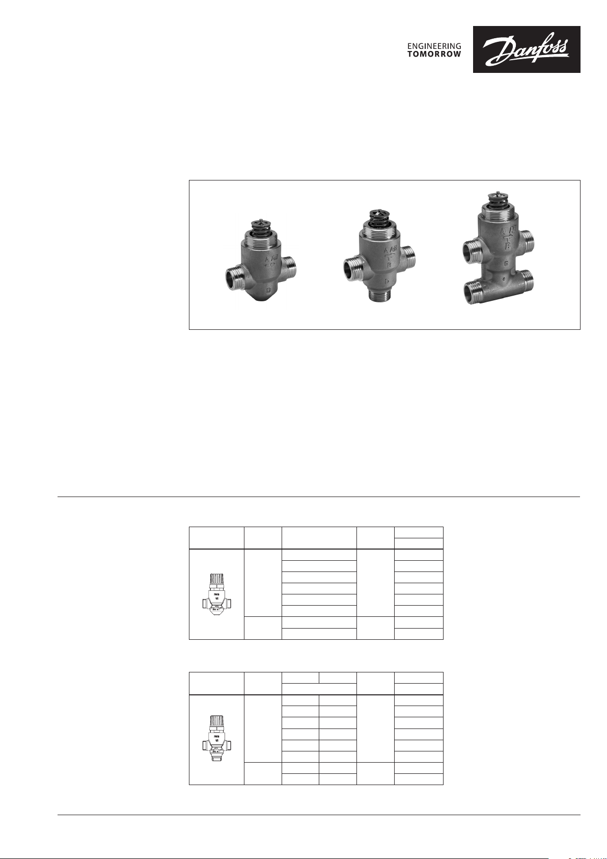
VZ 2 VZ 3 VZ 4
VZ valves provide a high quality, cost effective
solution for the control of hot and/or chilled
water for fan coil units, small reheaters, and
recoolers in temperature control systems.
The valves are used in combination with
AMV(E) 130/140, AMV(E) 130H/140H and
AMV(E) 13 SU actuators.
Ordering VZ 2 Valve
Picture
()* recommended ∆p
Main data:
• DN 15, 20
• kVS 0.25 - 4.0 m3/h
• PN 16
• Logarithmic flow characteristic
• Temperature:
- Circ. water / glycolic water up to 50%:
2 … 120 °C
• Reduced kVS on B port (VZ3 & VZ4 only)
• Linear bypass on 3 and 4 port valves
• Valves are supplied with screwed plastic
cover for manual operation
• Connections: flat end or conex
DN k
(mm) (m3/h) (bar) Flat End
15
20
VS
0.25
0.4 06 5Z 5311
0.63 06 5Z5312
1.0 0 65Z5 313
1.6 0 65Z5 314
2.5 065Z5315
2.5
4.0 065Z5321
Max. ∆p
3.5 (1)*
2.5 (1)*
Code No.
065 Z5310
065Z5320
VZ 3 Valve
Picture
()* recommended ∆p
DN
(mm)
15
20
kVS (A-AB) kVS (B-AB)
m3/h
0.25 0.25
0.4 0.25 06 5Z 5411
0.63 0.4 06 5Z5412
1.0 0.63 06 5Z5413
1.6 1.0 0 65Z5 414
2.5 1.6 0 65Z5415
2.5 1.6
4.0 2.5 065Z5421
Max. ∆p
(bar)
3.5 (1)*
2.5 (1)*
Code No.
Flat End
065Z5410
065Z5420
© Danfoss | 2018.08 VD.HB.I7.02 | 1
Data sheet VZ valve - 2/3/4-way
2
vs
valve
k
Q
S∆p
=
Ordering (continuous)
VZ 4 Valve
kVS (A-AB) k
Picture
()* recommended ∆p
DN
(mm)
15
20
0.25 0.25
0.4 0.25 065Z5511
0.63 0.4 065Z5512
1.0 0.63 065Z5513
1.6 1.0 065Z 5514
2.5 1.6 065Z 5515
2.5 1.6
4.0 2.5 065Z5521
NOTE:
kVS - is the flow in m3/h of water at a temp erature between 5 °C
and 40 °C whic h passes through a valve open at th e nominal
stroke with 100 kPa (1 bar) pressure d rop.
Max. Δp is the p hysical limit of differe ntial pressure the valve will
close against . The recommended Δp - values i n parentheses ()
is based on the ge neration of noise, plug ero sion etc. It should
be checked ag ainst the Δp figure calcul ated from the chart on
page 4 or the eq uation below, with the valve full y opened at the
designed f low rate.
m3/h
(B - AB)
VS
Max. ∆p
(bar)
3.5 (1)*
2.5 (1)*
S = specific g ravity
Q = flow rate in m3/h
Δp
valve
(fully open).
Conversion factors
1 bar = 100 kPa = 14.5 psi
1 l/s = 1 kg/s = 3.6 m3/h
Code No.
Flat End
065Z5510
065Z5520
= pressure drop across val ve in bar
Accessories
Connection Pipe size DN Description Code No.
Tailpieces with
external thread
R /” 15
R ½” 20 003H6902
Consist of 2 union nuts,
2 tailpieces and 2 gaskets (Ms 58)
065Z7015
Technical data
Connection Pipe size DN Description Code No.
Tailpieces for
soldering
Control characteristic Logarithmic
Control range min. 50:1
Leakage loss, closed valve
Medium Circulation water / Glycolic water up to 50 %
Medium temperature °C 2 … 120
Max. operating pressure bar 1
Stroke mm 5.5
Connection External thread (flat connection (MS 58) or conex))
Materials
Body, seat and cone Dezincing free brass CuZn36Pb2As
Stem Stainless steel
Stuffing box EPDM
12 m m 15
15 mm 20 06 5Z7017
Consist of 2 union nuts, 2 solder bushes
and 2 gaskets (Ms 58)
A - AB ≤ 0.05 % of kVS
B - AB ≤ 1 % of kVS
065 Z7016
2 | VD.HB.I7.02 © Danfoss | 2018.08
Data sheet VZ valve - 2/3/4-way
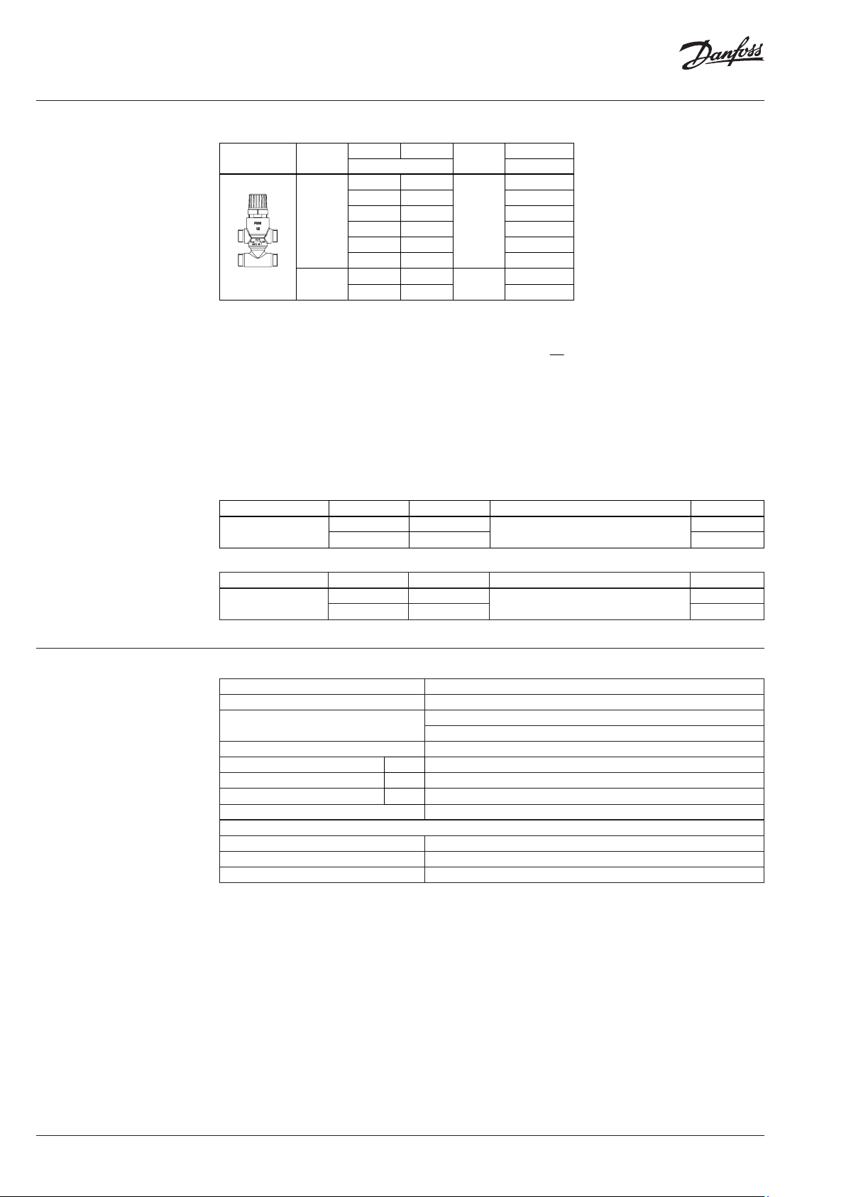
Pressure temperature
diagram
PN 16
Disposal
The valve must be dismantled and the elements
sorted into various material groups before
disposal.
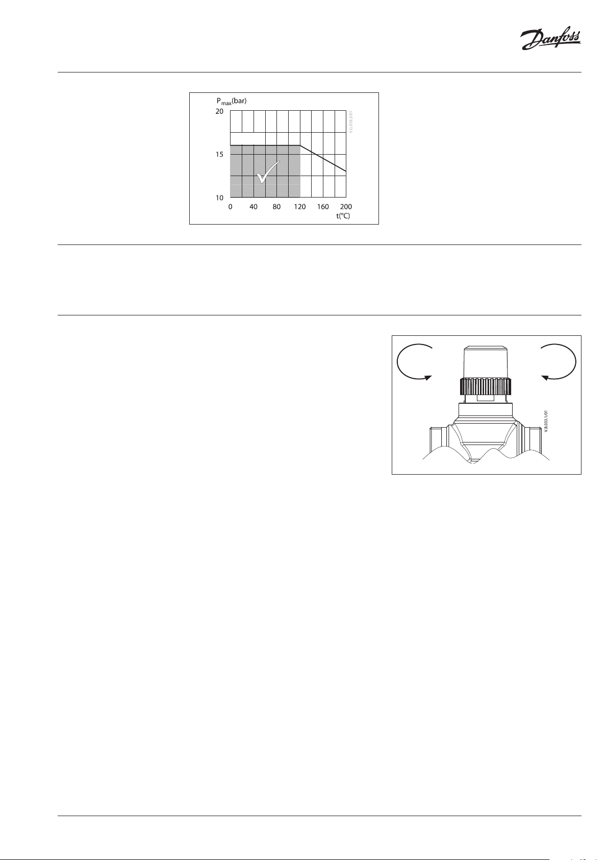
Manual operation Valves are supplied with screwed plastic cover
for manual operation.
Note: The flow is reduced on 75 % in case of
using plastic cover.
Closing
A-AB
Opening
A-AB
VD.HB.I7.02 | 3© Danfoss | 2018.08

Data sheet VZ valve - 2/3/4-way
Installation Hydraulic connections
Mount according to flow direction as indicated
on the valve body. AB is always the outlet port;
inlets are A (two port) or A and B (three or four
port).
Valve mounting
Before mounting the valve be sure that the pipes
are clean and free from swarf. It is essential that
the pipes are lined up squarely with the valve at
each connection and are free from vibrations.
The valve should be adequately supported to
prevent stress being applied to the connections
during operation. A maximum tightening
torque of 25 to 30 Nm should be applied to the
connections.
Install the valve so that the actuator will be
mounted in a vertical or horizontal position but
not upside down.
Leave sufficient clearance to allow the
dismantling of the actuator from the valve body
for maintenance purposes.
The valve must not be installed in an explosive
atmosphere or at an ambient temperature
higher than 50 °C or lower than 2 °C. It must not
be subjected to steam jets, water jets or dripping
liquid.
The valve is supplied complete with installation
instructions. The water quality should meet
VDI 2035 requirements.
AMV(E) 130/140, AMV(E) 130H/140H + VZ
AMV(E) 13 SU + VZ
Note that the actuator may be rotated up to
360° with respect to the valve body, by
loosening the retaining fixture. After this
operation retighten.
Ensure that the direction of flow is correct as
shown in typical application examples
(fig.1 and 2). The three way valve must be
installed as a mixing valve. If possible the valves
should be positioned in the return side.
Note:
Install a strainer upstream of the valve
(e.g. Danfoss FVR/FVF)
Fig. 1 Mixing valve used in mixing application
Fig. 2 Mixing valve used in diverting application
AMV(E)
FVR/FVF
4 | VD.HB.I7.02 © Danfoss | 2018.08

Data sheet VZ valve - 2/3/4-way
21
1
ΔPΔP
ΔP
N authority, Valve
56,0
0252
25
authority valve hence
31,0
029
9
authority valve hence
Sizing Example
Flow rate: 0.3 m3/h
System pressure drop: 20 kPa
Locate the horizontal line representing a flow
rate of 0.3 m3/h (line A). The valve authority is
given by the equation:
Where:
Δ P1 = pressure drop across the fully open valve,
Δ P2 = pressure drop across the rest of the circuit
with a fully open valve
The ideal valve would give a pressure drop equal
to the system pressure drop (i.e. an authority of
0.5):
If P1 = P
N = P1/2P1 = 0.5
In this example an authority of 0.5 would be
given by a valve having a pressure drop of 20 kPa
at that flow rate (point B).
The intersection of line A with a vertical line
drawn from B lies between two diagonal lines;
this means that no ideally-sized valve is available.
The intersection of line A with the diagonal lines
gives the pressure drops stated by real, rather
than ideal, valves. In this case, a valve with kVS 0.6
would give a pressure drop of 25 kPa (point C):
The second-largest valve, with kVS 1, would give a
pressure drop of 9 kPa (point D):
Generally, for a 3 port application, the smaller
valve would be selected (resulting in a valve
authority higher than 0.5, and therefore
improved controllability). However, this will
increase the total pressure and should be
2
checked by the system designer for compatibility
with available pump head, etc. The ideal
authority is 0.5 with a preferred range of
between 0.4 and 0.7.
Design
to close
A
2 Port
AB
to close A- AB
A AB
B
3 Port
to close A- AB
A AB
B B
4 Port
VD.HB.I7.02 | 5© Danfoss | 2018.08

Data sheet VZ valve - 2/3/4-way
Dimensions
92
92
92
H
h
L
d
H
d
h
L
H
d
h
L
AMV(E) 130/140 + VZ 4AMV(E) 130/140 + VZ 3AMV(E) 130/140 + VZ 2
92
1
H
1
h
d
c
L
AMV(E) 130H/140H + VZ .
2
H
AMV(E) 13 SU + VZ .
121
d
L
Valve t ype d
L H H
1
VZ 2 / DN 15 G ½” 65
VZ 2 / DN 20 G ¾” 77 0.49
VZ 3 / DN 15 G ½” 65
VZ 3 / DN 20 G ¾” 77 0.50
119 12 5 155
VZ 4 / DN 15 G ½” 65
VZ 4 / DN 20 G ¾” 77 50 0.62
Tailpieces for soldering
Ød L
G
½” 12 15 0.11
¾” 15 20 0.17
mm
Weight
(kg)
G
Ød
L
H
h h
2
1
mm
26.5
52.5
35
65
Tailpieces with external thread
R L Weig ht
G
(“) (mm) (kg)
½” ⁄ 23 0. 11
¾” ½ 26 0.17
c
Valve weight
-
40 0.51
G
(kg)
0.38
0.39
R
L
6 | VD.HB.I7.02 © Danfoss | 2018.08

Data sheet VZ valve - 2/3/4-way
VD.HB.I7.02 | 7© Danfoss | 2018.08

Data sheet VZ valve - 2/3/4-way
© Danfoss | DHS-SRMT/SI | 2018.088 | VD.HB.I7.02
 Loading...