

Danfoss VX Solo II, VX Solo II Series, VX Solo II H2, VX Solo II H, VX Solo II HWS Instructions Manual
...Page 1
Instructions
VX Solo II
VX Solo II VX Solo II H VX Solo II H2 VX Solo II HWP VX Solo II HWS
VX Solo II HWS VX Solo II H2WP VX Solo II H2WS VX Solo OP
1.0 Table of contents
1.0 Table of contents .......................................................................................................................................................................................................................1
2.0 Safety notes ................................................................................................................................................................................................................................2
3.0 Storage and Handling .............................................................................................................................................................................................................2
4.0 Disposal ........................................................................................................................................................................................................................................2
5.0 Diagrams - examples ...............................................................................................................................................................................................................3
6.0 Main components .................................................................................................................................................................................................................12
6.1 VX Solo II (T°C ) - 1 HE circuit + prim. connection for DHW cylinder ............................................................................................................12
6.2 VX Solo II H (ECL 210/A230.1a) - 1 HE circuit ........................................................................................................................................................ 13
6.3 VX Solo II H2 (ECL 210/A260.1d) -2 HE circuits.....................................................................................................................................................14
6.4 VX Solo II HWP (ECL 210/A237) - 1 HE circuit + prim. connection for DHW cylinder .............................................................................15
6.5 VX Solo II HWS (ECL 210/A237.1a) - 1 HE circuit + sec. connection for DHW cylinder .......................................................................... 16
6.6 VX Solo II HWS (ECL 210/A247.1c) - 1 HE circuit + mixing loop + sec. connection for DHW cylinder ............................................. 17
6.7 VX Solo II H2WP (ECL 210/A260.1d) - 2 HE circuit + prim. connection for DHW cylinder .................................................................... 18
6.8 VX Solo II H2WS (ECL 310/A367.1d) - 2 HE circuits + sec. connection for DHW cylinder .....................................................................19
6.9 VX Solo OP (ECL 210/A237.1a) - 1 HE circuit + sec. connection for DHW cylinder ................................................................................. 20
7.0 Mounting .................................................................................................................................................................................................................................. 21
7.1 Variable connection possibilities ............................................................................................................................................................................. 21
7.2 Tightening of connections ......................................................................................................................................................................................... 21
7.3 Expansion vessel ............................................................................................................................................................................................................ 21
7.4 Heat meter, Fitting pieces ........................................................................................................................................................................................... 22
7.5 Mounting of outdoor temperature sensor ...........................................................................................................................................................22
7.6 Mounting of immersion sensor ................................................................................................................................................................................ 22
8.0 Filling, Start-up ...................................................................................................................................................................................................................... 23
9.0 Manometer and filling ........................................................................................................................................................................................................ 23
10.0 Electrical connections .........................................................................................................................................................................................................23
11.0 Description of VX Solo variants ........................................................................................................................................................................................ 24
11.1 VX Solo II (T°C 200u) .................................................................................................................................................................................................... 24
11.2 VX Solo II H (ECL 210/A230.1a) ................................................................................................................................................................................ 26
11.3 VX Solo II H2 (ECL 210/A260.1d) ............................................................................................................................................................................. 28
11.4 VX Solo II HWP (ECL 210/A237) ............................................................................................................................................................................... 31
11.5 VX Solo II HWS (ECL 210/A237.1a) ......................................................................................................................................................................... 34
11.6 VX Solo II HWS (ECL 210/A247.1c) .........................................................................................................................................................................37
11.7 VX Solo II H2WP (ECL 210/A260.1d) ...................................................................................................................................................................... 40
11.8 VX Solo II H2WS (ECL 310/A367.1d) ......................................................................................................................................................................43
11.9 VX Solo OP (ECL 210/A237.1a) ................................................................................................................................................................................ 46
12.0 Circulation pumps ................................................................................................................................................................................................................ 48
13.0 Maintenance ........................................................................................................................................................................................................................... 50
14.0 Troubleshooting .................................................................................................................................................................................................................... 51
15.0 EC-Declaration of Conformity ..........................................................................................................................................................................................55
Danfoss District Energy VI.GP.P1.02 DKDHR
1
Page 2
Instructions VX Solo II
2.0 Safety notes
Instructions
This operating manual should be read carefully before installation and
start-up of the substation. The manufacturer accepts no liability for
damage or faults that result from non-compliance with the operating
manual.
Please read and follow all the instructions carefully to prevent accidents, injury and damage to property. The risk of persons being injured
and equipment damaged increases considerably if the recommended
permissible operating parameters are exceeded.
Installation, assembly work, first start-up and maintenance work may
be carried out only by qualified and authorized personnel in compliance with the safety regulations (both heating and electrical work).
Connection
The substation must be equipped with features that ensure that
the substation can be separated from all energy sources (also
power supply).
Warning of hot surfaces
Parts of the substation may become hot and hot surfaces can
cause serious burns. Please be extremely cautious in close proximi-ty to the substation.
Energy source
The substation is designed for district heating as the primary source
of energy. However, also other energy sources can be used where the
operating conditions allow it and always are comparable to district
heating.
Application
The substation is designed only to operate with water or a water-glycol
mixture (up to 40%), and other heating media may not be used.
Connect the substation to the house installation in a frost-free room,
where the temperature does not exceed 50 °C and the humidity does
not exceed 80%. Do not cover or wall up the substation or in any other
way block the entrance to the station.
Choice of material
Choice of materials always in compliance with local legislation.
Corrosion protection
The maximum chloride compounds of the flow medium should not
be higher than 300 mg/l. The risk of equipment corrosion increases
considerably if the recommended permissible chloride compounds
are exceeded.
Safety valve(s)
We recommend mounting of safety valve(s), however, always in compliance with local regulations.
Sound level.
≤ 55 dB.
Warning of high pressure and high temperature
The stations work at a maximum supply temperature from the
district heating network of 110°C and the stations work with a operating pressure of 16 bar, which may put the user at risk of burns
from touching the surface or from the emissions of hot media
(water/steam). The risk of persons being injured and equipment
damaged increases considerably if the recommended permissible
operating parameters are exceeded.
Emergency
In case of danger or accidents - fire, leaks or other dangerous circumstances - interrupt all energy sources to the station if possible,
and seek expert help.
In case of discoloured or bad-smelling domestic hot water, close
all shut-off valves on the substation, inform the operating personnel and call for expert help immediately.
Warning of transport damage
Before substation installation, please make sure that the substation has not been damaged during transport. Always transport
the substation with the utmost care and caution.
IMPORTANT - Tightening of connections
Due to vibrations during transport all flange connections, screw
joints and electrical clamp and screw connections must be checked and tightened before water is added to the system.
After water has been added to the system and the system has
been put into operation, re-tighten ALL connections.
(Do not overstrain! - See item 7.2)
3.0 Storage and Handling
If the substation is stored before installation, make sure that the place
is dry and heated.
(Humidity max. 80% and storage temperature 5-70 °C).
Do not stack the unit higher than factory shipped. Units that are
shipped in cardboard packaging are to be lifted by the carrying
handles of the packaging. Transport / removals over great distances
should be carried out on pallets.
During and after unpacking, the substation can be lifted by using
straps, fitted around the pipes or it can be lifted by hand in the
pipes Lifting in the pipes can cause leaks. ALWAYS re-tighten.
Handling
When working on the substation suitable safety shoes must be
worn.
4.0 Disposal
Dispose of packaging material in accordance with local regulations.
This product consists of materials, which must not be disposed of
together with domestic waste. Switch off the complete power supply and dismantle the product and sort the components in various
groups before disposal. Always observe the disposal rules of the local
legislation.
2
DKDHR VI.GP.P1.02 Danfoss District Energy
Page 3
Instructions VX Solo II
5.0 Diagrams - examples
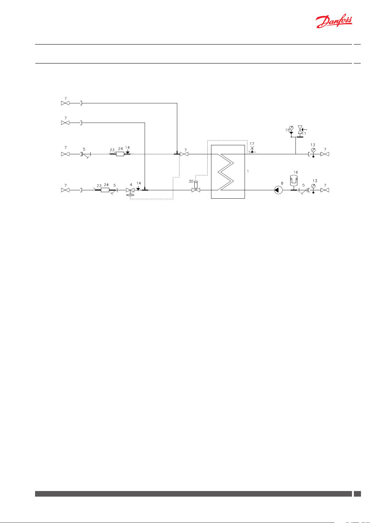
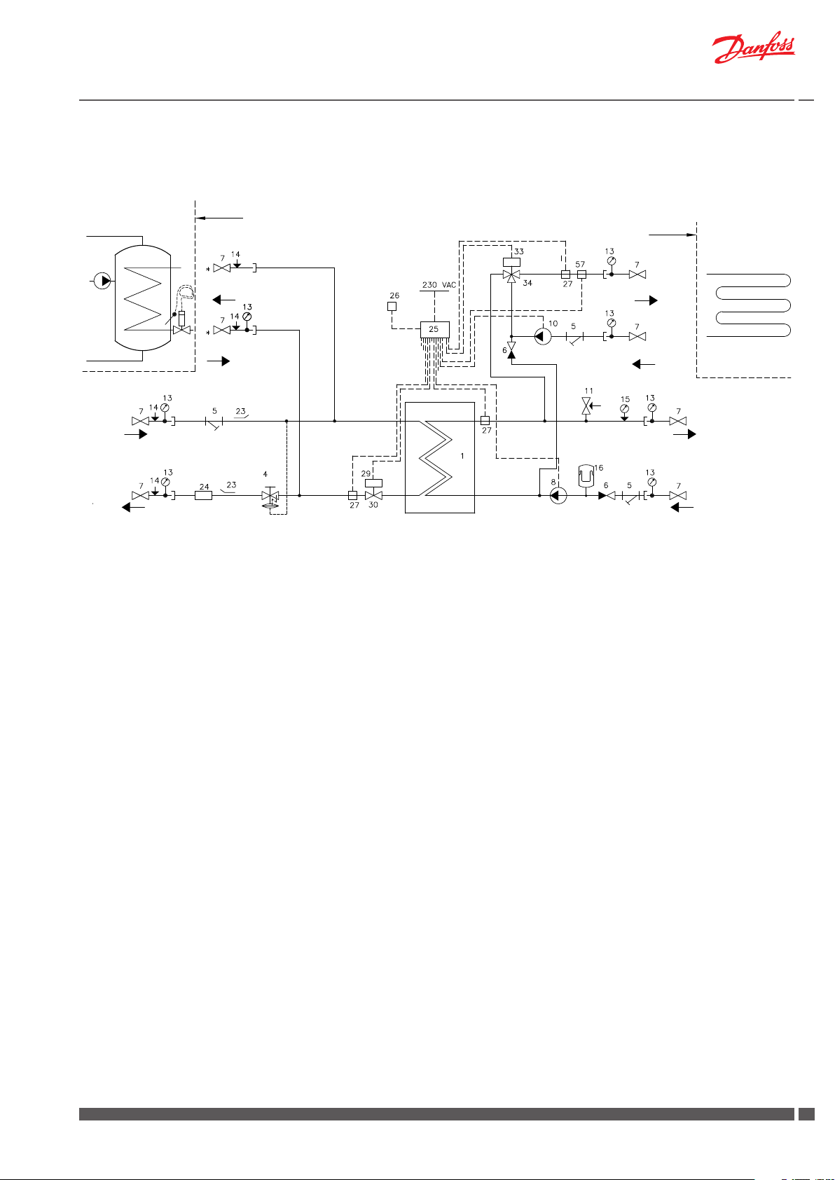
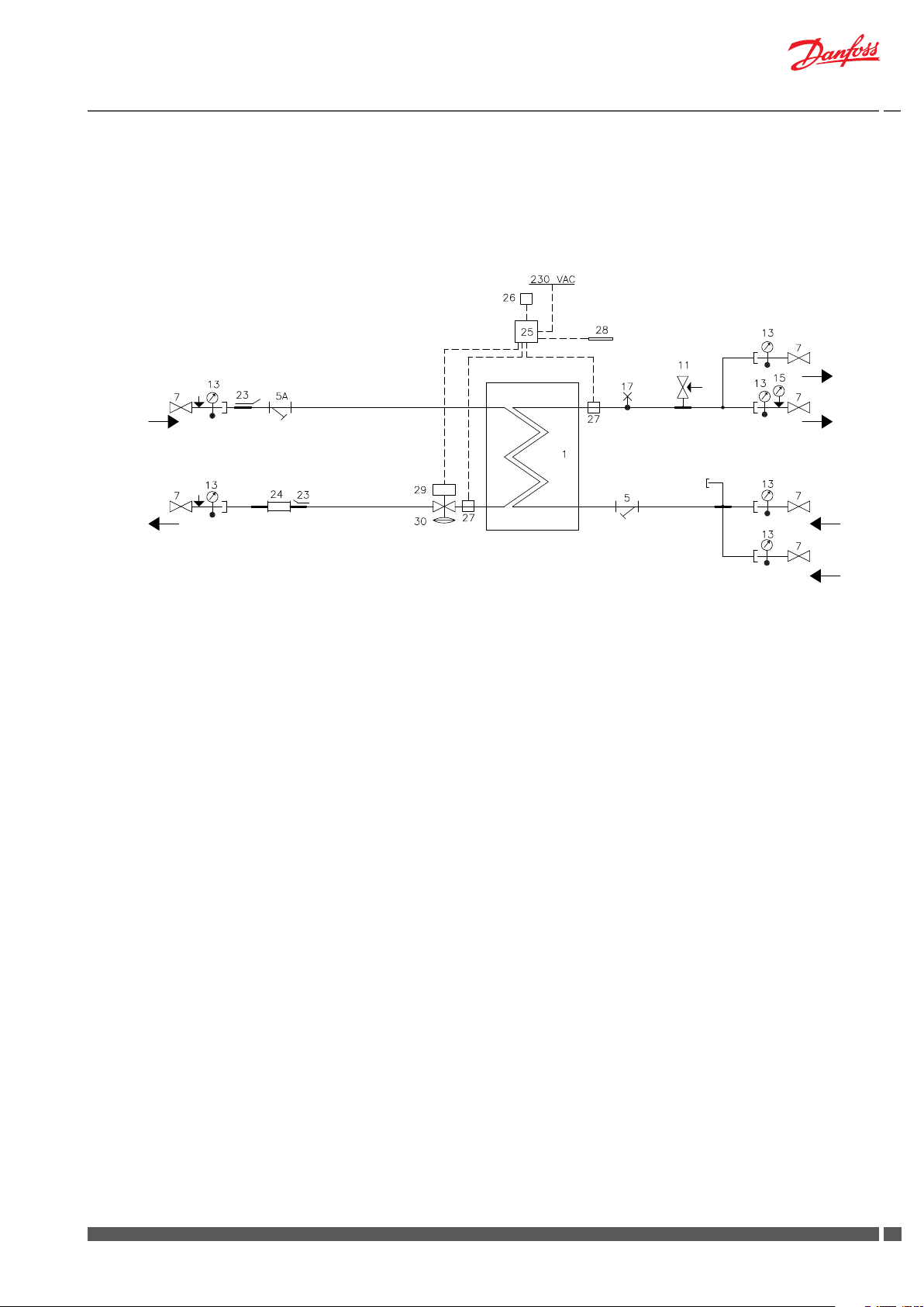
5.1 VX Solo II (T°C 200u) - 1 HE ciruit + primary connection pipes for cylinder
DH
Supply
DH
Return
1 Plate heat exchanger, HE, with insulation
4 Differential pressure controller AVPL
5 Strainer
7 Ball valve
8 Circulation pump HE
11 Safety valve, HE 2.5 bar
13 Thermometer
14 Pocket for pressure gauge
15 Manometer
16 Expansion vessel
17 Air vent
23 Sensor pocket for heat meter ½“
24 Fitting piece for heat meter, 3/4” x 110 mm
30 Self-acting thermostatic valve T°C 200/VS 2-15
HE
Supply
HE
Return
Danfoss District Energy VI.GP.P1.02 DKDHR
33
Page 4
Instructions VX Solo II
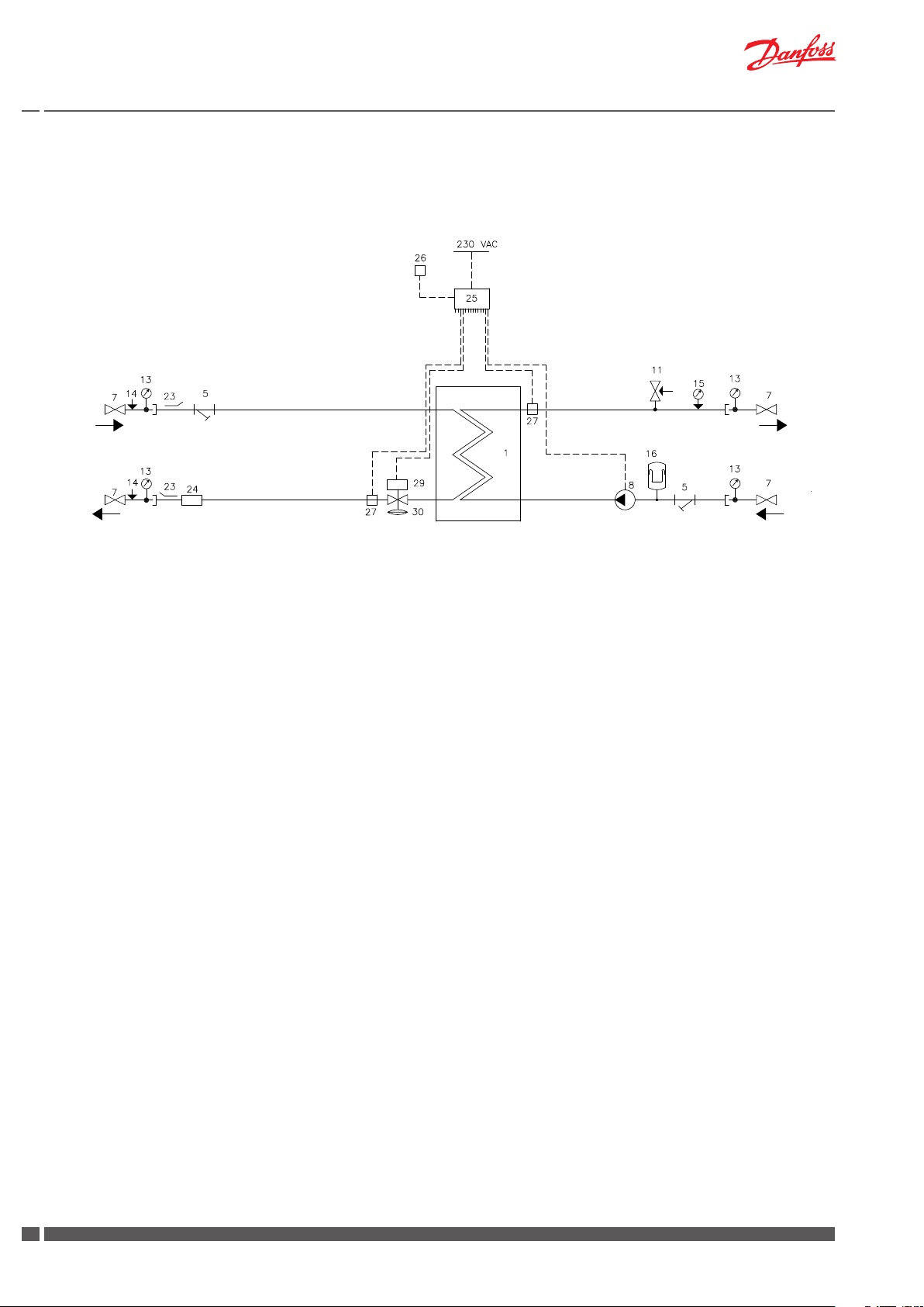
5.2 VX Solo II H (ECL 210/A230.1a) - 1 HE circuit
DH
Supply
DH
Return
1 Plate heat exchanger, HE, with insulation
5 Strainer
7 Ball valve
8 Circulation pump HE
11 Safety valve, HE
13 Thermometer
14 Pocket for pressure gauge
15 Manometer
16 Expansion vessel
23 Sensor pocket for heat meter ½“
24 Fitting piece for heat meter, 3/4” x 110 mm
25 Controller Danfoss ECL 210/A230.1a
26 Outdoor sensor Danfoss ESMT
27 Sensor Danfoss ESMC
29 Danfoss actuator AMV150
30 Danfoss flow controller with integrated control valve AHQM
HE
Supply
HE
Return
4
DKDHR VI.GP.P1.02 Danfoss District Energy
Page 5
Instructions VX Solo II
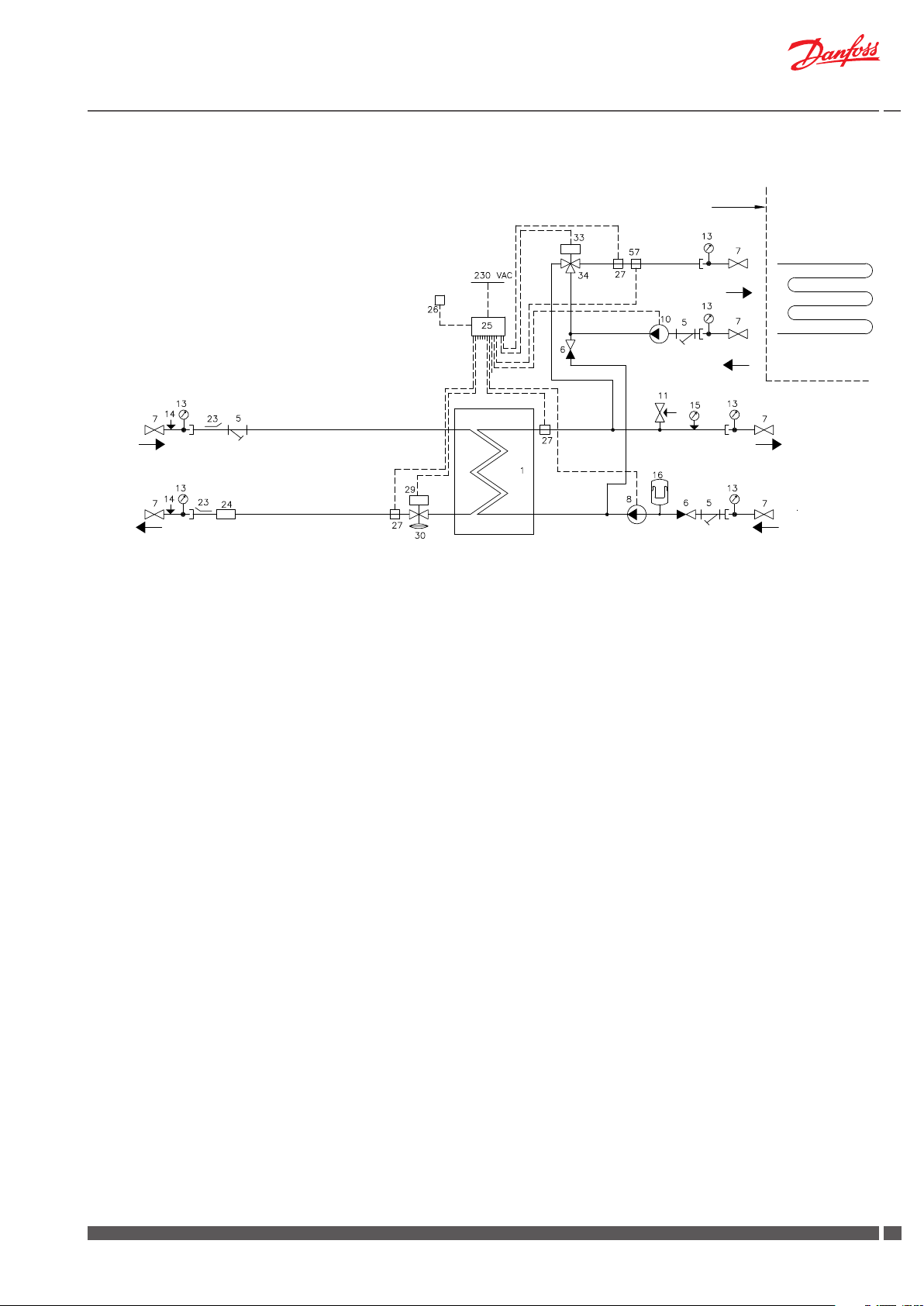
5.3 VX Solo II H2 (ECL 210/A260.1d) - 2 HE circuits
Supply limit
FH
Supply
FH
Return
DH
Supply
DH
Return
1 Plate heat exchanger, HE, with insulation
5 Strainer
6 Non-return valve
7 Ball valve
8 Circulation pump HE
10 Circulation pump FH
11 Safety valve, HE
13 Thermometer
14 Pocket for pressure gauge
15 Manometer
16 Expansion vessel
23 Sensor pocket for heat meter ½“
24 Fitting piece for heat meter, 3/4” x 110 mm
25 Controller Danfoss ECL 210/A260.1d
26 Outdoor sensor Danfoss ESMT
27 Sensor Danfoss ESMC
29 Danfoss actuator AMV13
30 Danfoss flow controller with integrated control valve AHQM
33 Danfoss actuator AMV150
34 3-way valve VMV 30/15
57 Safety temperature monitor Jumo AT
HE
Supply
HE
Return
Danfoss District Energy VI.GP.P1.02 DKDHR
55
Page 6

Instructions VX Solo II
5.4 VX Solo II HWP (ECL 210/A237) - 1 HE circuit + primary connection pipes for DHW cylinder
Supply limit
Cylinder
Cylinder
Supply
Cylinder
Return
DH
Supply
DH
Return
1 Plate heat exchanger, HE, with insulation
4 Differential pressure controller with flow limitation AVPB-F
5 Strainer
7 Ball valve
8 Circulation pump HE
11 Safety valve, HE
13 Thermometer
14 Pocket for pressure gauge
15 Manometer
16 Expansion vessel
23 Sensor pocket for heat meter ½“
24 Fitting piece for heat meter, 3/4” x 110 mm
25 Controller Danfoss ECL 210/A237
26 Outdoor sensor Danfoss ESMT
27 Sensor Danfoss ESMC
29 Danfoss actuator AMV150
30 2-way valve VS2
HE
Supply
HE
Return
6
DKDHR VI.GP.P1.02 Danfoss District Energy
Page 7
Instructions VX Solo II
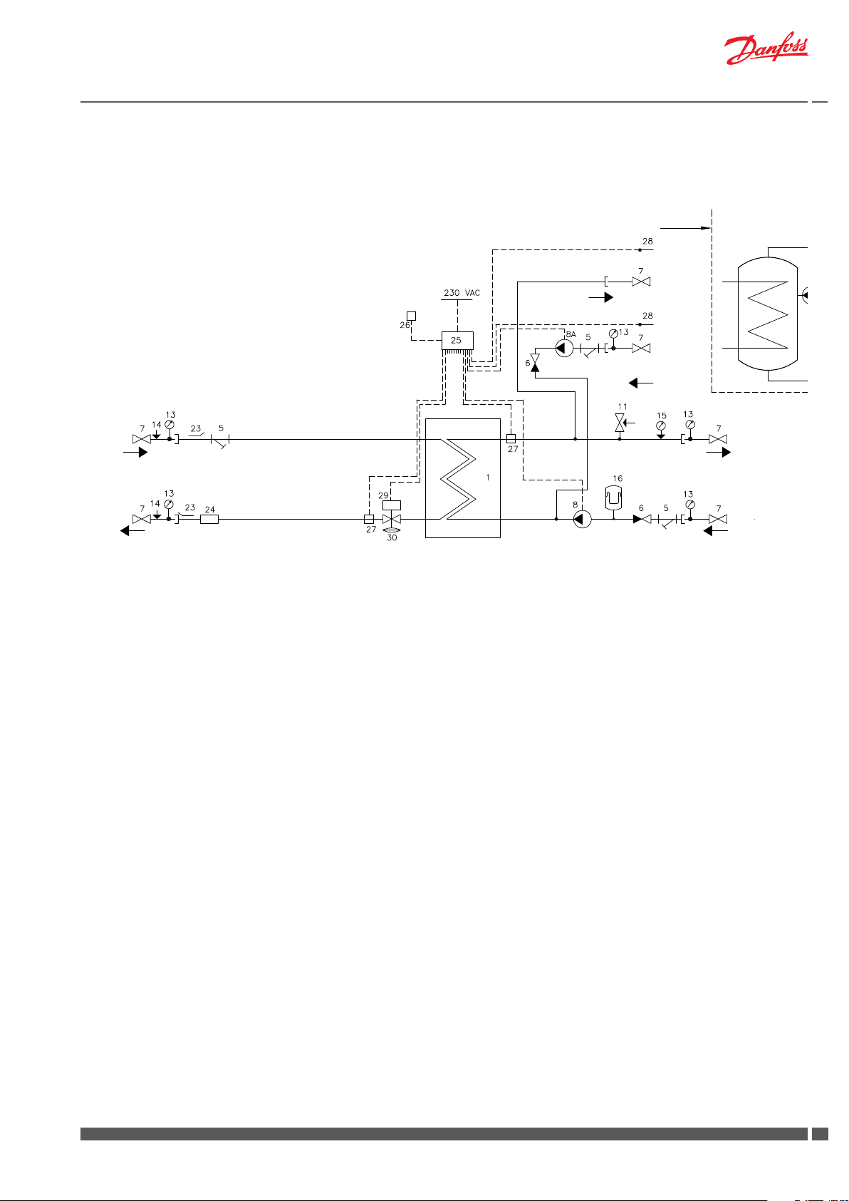
5.5 VX Solo II HWS (ECL 210/A237.1a) - 1 HE circuit + secondary connection pipes for DHW cylinder
Supply limit
Cylinder
Cylinder
Supply
Cylinder
Return
DH
Supply
DH
Return
1 Plate heat exchanger, HE, with insulation
5 Strainer
6 Non-return valve
7 Ball valve
8 Circulation pump HE
8A Circulation pump Cylinder
11 Safety valve, HE
13 Thermometer
14 Pocket for pressure gauge
15 Manometer
16 Expansion vessel
23 Sensor pocket for heat meter ½“
24 Fitting piece for heat meter, 3/4” x 110 mm
25 Controller Danfoss ECL 210/A237.1a
26 Outdoor sensor Danfoss ESMT
27 Sensor Danfoss ESMC
28 Immersion sensor Danfoss ESMB
29 Danfoss actuator AMV13
30 Danfoss flow controller with integrated control valve AHQM
HE
Supply
HE
Return
Danfoss District Energy VI.GP.P1.02 DKDHR
77
Page 8
Instructions VX Solo II
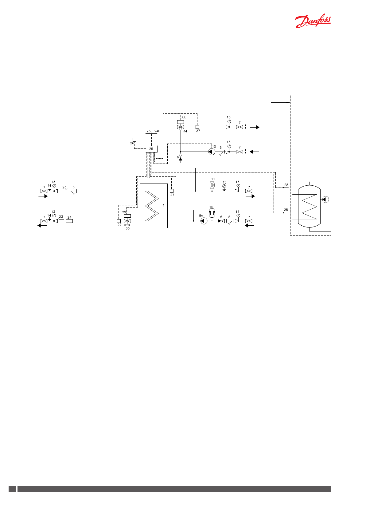
5.6 VX Solo II HWS (ECL 210/A247.1c) - 1 HE circuit + mixing loop + secondary connection pipes for DHW cylinder
Supply limit
HE
Supply
HE
Return
Radiator heating/
Floor heating
Cylinder
DH
Supply
DH
Return
1 Plate heat exchanger, HE, with insulation
5 Strainer
6 Non-return valve
7 Ball valve
8A Circulation pump HE
10 Circulation pump Cylinder
11 Safety valve, HE
13 Thermometer
14 Pocket for pressure gauge
15 Manometer
16 Expansion vessel
23 Sensor pocket for heat meter ½“
24 Fitting piece for heat meter, 3/4” x 110 mm
25 Controller Danfoss ECL 210/A247.1c
26 Outdoor sensor Danfoss ESMT
27 Sensor Danfoss ESMC
28 Immersion sensor Danfoss ESMB
29 Danfoss actuator AMV150
30 Danfoss flow controller with integrated control valve AHQM
33 Danfoss actuator AMV150
34 3-way valve VMV 30/15
Cylinder
Supply
Cylinder
Return
8
DKDHR VI.GP.P1.02 Danfoss District Energy
Page 9
Instructions VX Solo II
5.7 VX Solo II H2WP (ECL 210/A260.1d) - 2 HE circuit + primary connection pipes for DHW cylinder
Supply limit
Cylinder
Cylinder
Supply
Cylinder
Return
Supply limit
FH
Supply
FH
Return
DH
Supply
DH
Return
1 Plate heat exchanger, HE, with insulation
4 Differential pressure controller with flow limitation AVPB-F
5 Strainer
6 Non-return valve
7 Ball valve
8 Circulation pump HE
10 Circulation pump FH
11 Safety valve, HE
13 Thermometer
14 Pocket for pressure gauge
15 Manometer
16 Expansion vessel
23 Sensor pocket for heat meter ½“
24 Fitting piece for heat meter, 3/4” x 110 mm
25 Controller Danfoss ECL 210/A260.1d
26 Outdoor sensor Danfoss ESMT
27 Sensor Danfoss ESMC
29 Danfoss actuator AMV13
30 2-way valve VS2
33 Danfoss actuator AMV150
34 3-way valve VMV 30/15
57 Safety temperature monitor Jumo AT
HE
Supply
HE
Return
Danfoss District Energy VI.GP.P1.02 DKDHR
99
Page 10

Instructions VX Solo II
5.8 VX Solo II H2WS (ECL 310/A367.1d) - 2 HE circuits + secondary connection pipes for DHW cylinder
DH
Supply
DH
Return
Supply limit
Cylinder
Supply
Cylinder
Return
FH
Supply
FH
Return
Cylinder
HE
Supply
HE
Return
1 Plate heat exchanger, HE, with insulation
5 Strainer
6 Non-return valve
7 Ball valve
8 Circulation pump HE
8A Circulation pump Cylinder
10 Circulation pump FH
11 Safety valve, HE
13 Thermometer
15 Manometer
16 Expansion vessel
23 Sensor pocket for heat meter ½“
24 Fitting piece for heat meter, 3/4” x 110 mm
25 Controller Danfoss ECL 310/A367.1d
26 Outdoor sensor Danfoss ESMT
27 Sensor Danfoss ESMC
28 Immersion sensor Danfoss ESMB
29 Danfoss actuator AMV13
30 Danfoss flow controller with integrated control valve AHQM
33 Danfoss actuator AMV150
34 3-way valve VMV 30/15
57 Safety temperature monitor Jumo AT
10
DKDHR VI.GP.P1.02 Danfoss District Energy
Page 11
Instructions VX Solo II
5.9 VX Solo OP (ECL 210/A237.1a) - 1 HE circuit + secondary connection pipes for DHW cylinder
Cylinder
Supply
DH
Supply
DH
Return
1 Plate heat exchanger, HE, with insulation
5 Strainer
6 Non-return valve
7 Ball valve
11 Safety valve, HE
13 Thermometer
15 Manometer
17 Air valve
23 Sensor pocket for heat meter ½“
24 Fitting piece for heat meter, 3/4” x 110 mm
25 Controller Danfoss ECL 210/A237.1a
26 Outdoor sensor Danfoss ESMT
27 Sensor Danfoss ESMC
28 Immersion sensor Danfoss ESMB
29 Danfoss actuator AMV10
30 Danfoss flow controller with integrated control valve AVQM
HE
Supply
Conn. for
expansion vessel
HE
Return
Cylinder
Return
Danfoss District Energy VI.GP.P1.02 DKDHR
1111
Page 12
Instructions VX Solo II
6.0 Main components
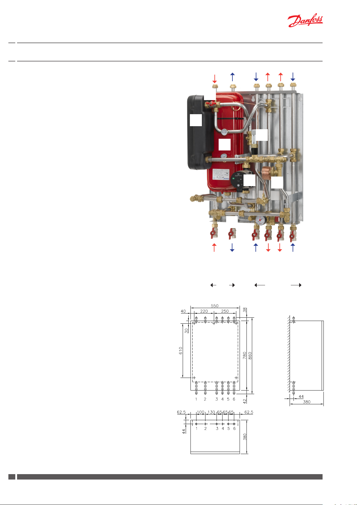
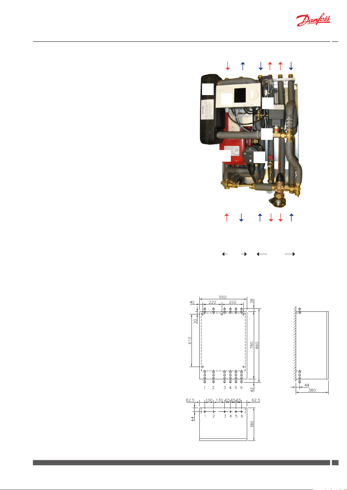
6.1 VX Solo II (T°C ) - 1 HE circuit + prim. connection for DHW cylinder
1 Plate heat exchanger
4 Differential pressure controller
8 Circulation pump, HE
16 Expansion vessel
17 Air valve
24 Fitting piece for heat meter
30 Thermostat T°C 200
17
1
The substations offer variable connection possibilities, as
connection of pipes can be established both in the top or in
the bottom of the substation.
Please note:
Your substation may look different than the substation shown, as
variants with other components may be supplied. The control function, however, is basically as stated in this instruction manual.
Instructions for the fitted components will be supplied together with
the substation.
16
24
8
24
DH supply
DH returnf
Primary Secundary
30
HE return
4
HE supply
Cylinder return
Cylinder supply
Measurements:
Dimensions without cover
H860 x W510 x D345 mm
Dimensions with cover
H860 x W550 x D380 mm
Connections:
Order:
1 District heating (DH) supply
2 District heating (DH) return
3 Heating (HE) return
4 Heating (HE) supply
5 Cylinder supply
6 Cylinder return
Connection sizes (example:
DH: G¾ (ET)
HE: G¾ (IT)
top view
12
DKDHR VI.GP.P1.02 Danfoss District Energy
Wall
Page 13
Instructions VX Solo II
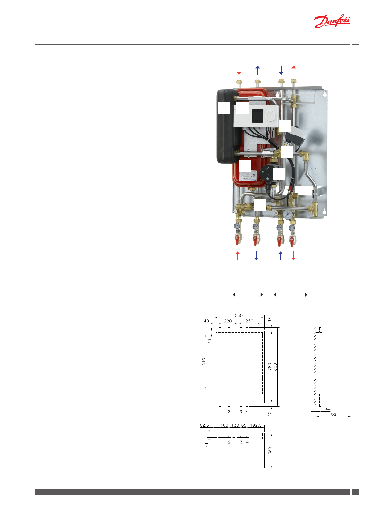
6.2 VX Solo II H (ECL 210/A230.1a) - 1 HE circuit
1 Plate heat exchanger
8 Circulation pump, HE
16 Expansion vessel
24 Fitting piece for heat meter
25 Electronic controller
29 Actuator AMV 13
30 Flow controller with integrated control valve AHQM
1
25
The substations offer variable connection possibilities, as
connection of pipes can be established both in the top or in
the bottom of the substation.
Please note:
Your substation may look different than the substation shown, as
variants with other components may be supplied. The control function, however, is basically as stated in this instruction manual.
Instructions for the fitted components will be supplied together with
the substation.
24
16
24
DH supply
DH return
Primary Secundary
29
30
8
HE return
HE supply
Measurements:
Dimensions without cover
H860 x W530 x D365 mm
Dimensions with cover
H860 x W550 x D380 mm
Connections:
Order:
1 District heating (DH) supply
2 District heating (DH) return
3 Heating (HE) return
4 Heating (HE) supply
Connection sizes (example:
DH: G¾ (ET)
HE + FH: G¾ (IT)
top view
Danfoss District Energy VI.GP.P1.02 DKDHR
Wall
1313
Page 14
Instructions VX Solo II
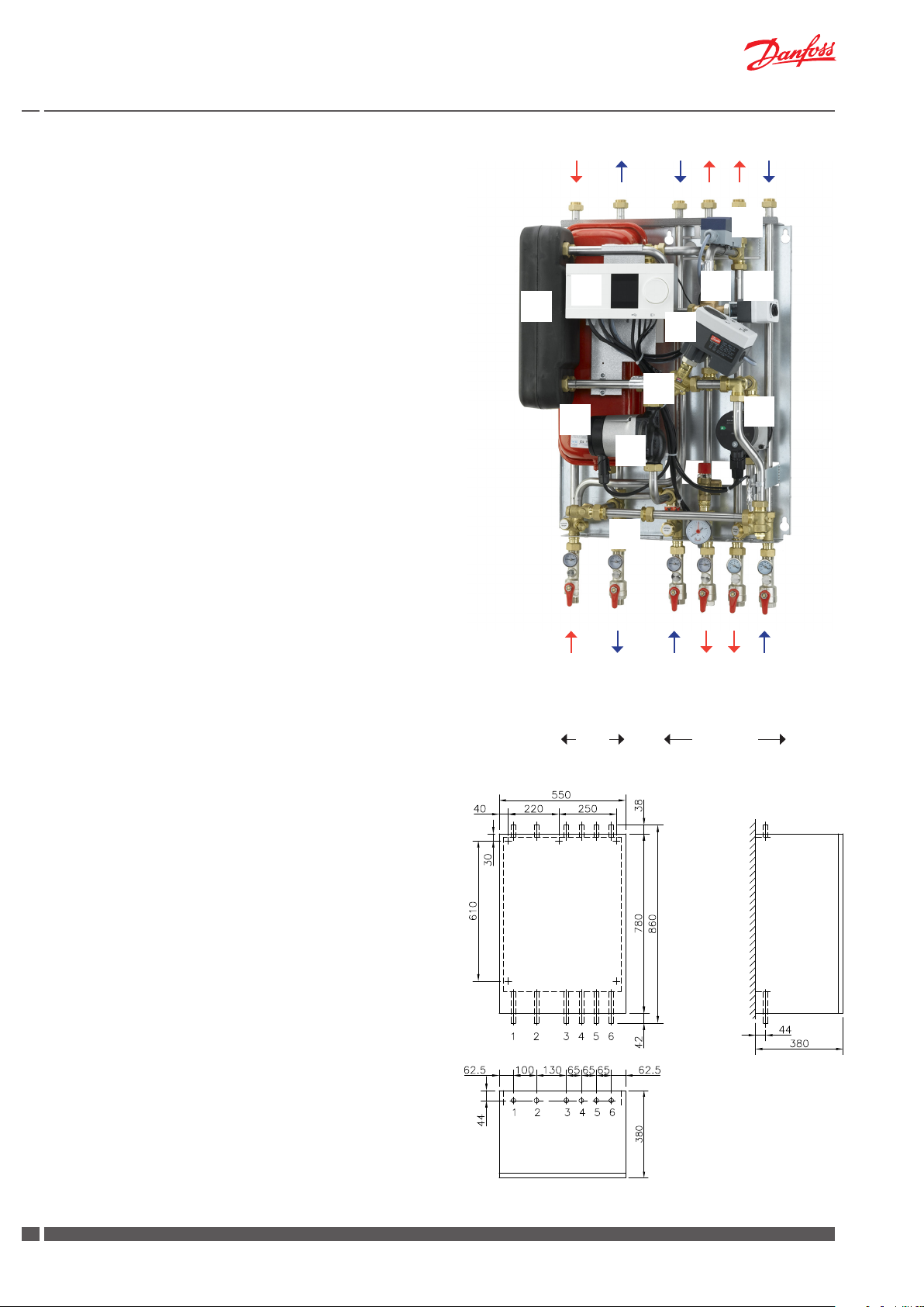
6.3 VX Solo II H2 (ECL 210/A260.1d) -2 HE circuits
1 Plate heat exchanger
8 Circulation pump, HE
10 Circulation pump, FH
16 Expansion vessel
24 Fitting piece for heat meter
25 Electronic controller
29 Actuator AMV 13)
30 Flow controller with integrated control valve AHQM
33 Actuator AMV150
34 3-way valve VMV 30/15
57 Safety temperature monitor
The substations offer variable connection possibilities, as
connection of pipes can be established both in the top or in
the bottom of the substation.
Please note:
Your substation may look different than the substation shown, as
variants with other components may be supplied. The control function, however, is basically as stated in this instruction manual.
57
34
25
33
1
29
30
16
10
8
Instructions for the fitted components will be supplied together with
the substation.
Measurements:
Dimensions without cover
H860 x W530 x D365 mm
Dimensions with cover
H860 x W550 x D380 mm
Connections:
Order:
1 District heating (DH) supply
2 District heating (DH) return
3 Heating (HE) return
4 Heating (HE) supply
5 Floor heating (FH) supply
6 Floor heating (FH) return
24
DH supply
DH return
Primary Secundary
HE return
HE supply
FH supply
FH return
Connection sizes (example:
DH: G¾ (ET)
HE + FH: G¾ (IT)
top view
14
DKDHR VI.GP.P1.02 Danfoss District Energy
Wall
Page 15
Instructions VX Solo II
6.4 VX Solo II HWP (ECL 210/A237) - 1 HE circuit + prim. connection for DHW cylinder
1 Plate heat exchanger
4 Differential pressure controller
8 Circulation pump, HE
16 Expansion vessel
24 Fitting piece for heat meter
25 Electronic controller
29 Actuator AMV 150
30 2-way valve VS2
The substations offer variable connection possibilities, as
connection of pipes can be established both in the top or in
the bottom of the substation.
Please note:
Your substation may look different than the substation shown, as
variants with other components may be supplied. The control function, however, is basically as stated in this instruction manual.
Instructions for the fitted components will be supplied together with
the substation.
1
25
16
29
30
8
24
4
Measurements:
Dimensions without cover
H860 x W530 x D365 mm
Dimensions with cover
H860 x W550 x D380 mm
Connections:
Order:
1 District heating (DH) supply
2 District heating (DH) return
3 Heating (HE) return
4 Heating (HE) supply
5 Cylinder (FH) supply
6 Cylinder (FH) return
Connection sizes (example:
DH: G¾ (ET)
HE + FH: G¾ (IT)
Wall
HE return
HE supply
DH return
DH supply
Primary Secundary
Cylinder return
Cylinder supply
top view
Danfoss District Energy VI.GP.P1.02 DKDHR
1515
Page 16
Instructions VX Solo II
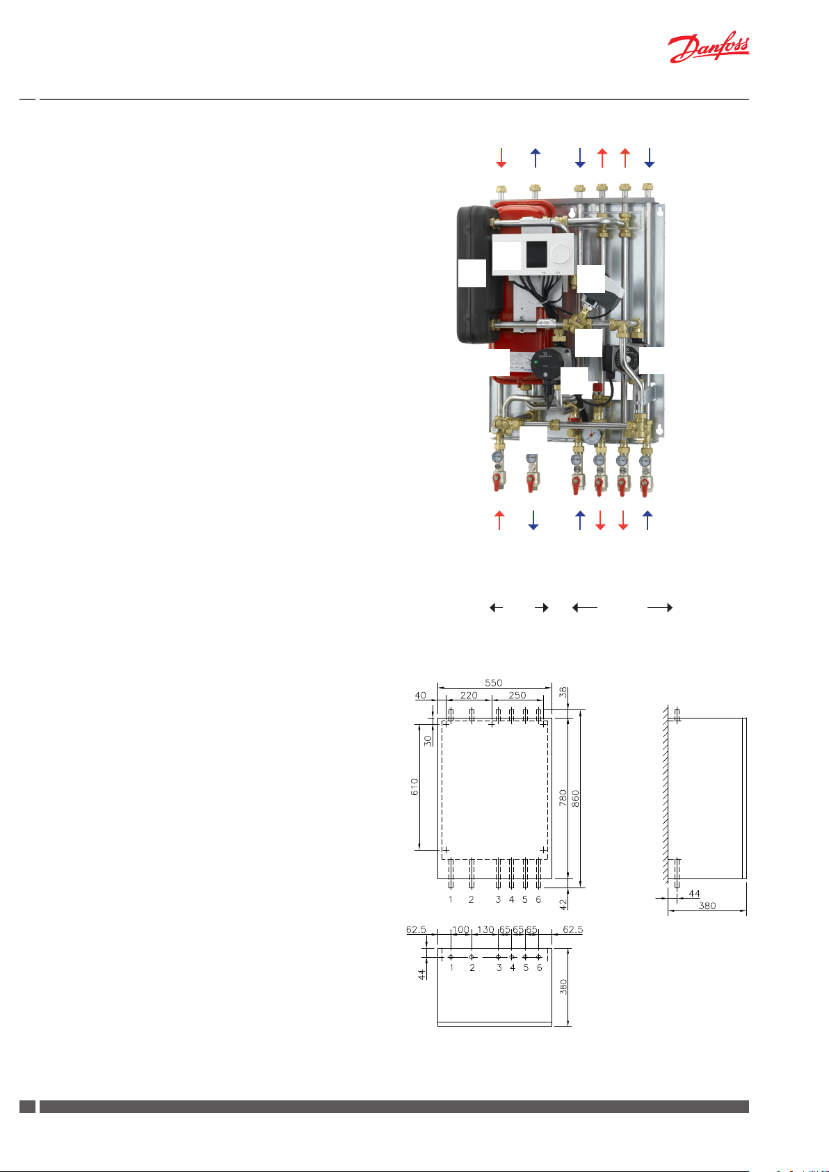
6.5 VX Solo II HWS (ECL 210/A237.1a) - 1 HE circuit + sec. connection for DHW cylinder
1 Plate heat exchanger
8 Circulation pump, HE
8A Circulation pump, Cylinder
16 Expansion vessel
24 Fitting piece for heat meter
25 Electronic controller
29 Actuator AMV 150
30 Flow controller with integrated control valve AHQM
The substations offer variable connection possibilities, as connection of pipes can be established
both in the top or in the bottom of the substation.
Please note:
Your substation may look different than the substation shown, as
variants with other components may be supplied. The control function, however, is basically as stated in this instruction manual.
Instructions for the fitted components will be supplied together with
the substation.
25
1
16
29
30
8A
8
24
Measurements:
Dimensions without cover
H860 x W530 x D365 mm
Dimensions with cover
H860 x W550 x D380 mm
Connections:
Order:
1 District heating (DH) supply
2 District heating (DH) return
3 Heating (HE) return
4 Heating (HE) supply
5 Cylinder (FH) supply
6 Cylinder (FH) return
Connection sizes (example:
DH: G¾ (ET)
HE + FH: G¾ (IT)
DHreturn
DH supply
Primary Secundary
Wall
HE return
HE supply
Cylinder return
Cylinder supply
top view
16
DKDHR VI.GP.P1.02 Danfoss District Energy
Page 17
Instructions VX Solo II
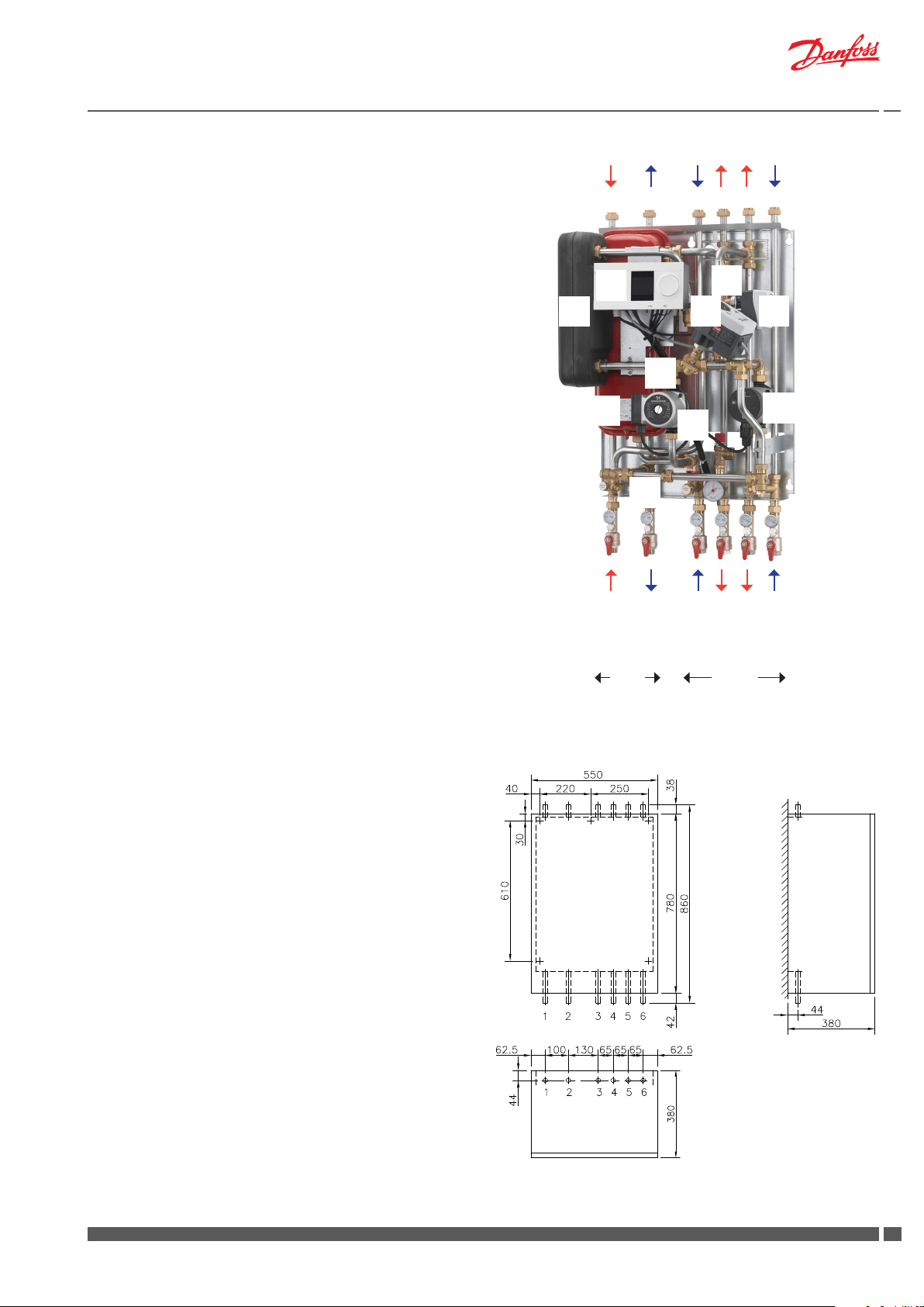
6.6 VX Solo II HWS (ECL 210/A247.1c) - 1 HE circuit + mixing loop + sec. connection for DHW cylinder
1 Plate heat exchanger
8A Circulation pump, Cylinder
10 Circulation pump, HE
16 Expansion vessel
24 Fitting piece for heat meter
25 Electronic controller
29 Actuator AMV 150
30 Flow controller with integrated control valve AHQM
33 Actuator AMV150
34 3-way valve VMV 30/15
The substations offer variable connection possibilities, as
connection of pipes can be established both in the top or in
the bottom of the substation.
25
1
30
29
34
33
Please note:
Your substation may look different than the substation shown, as
variants with other components may be supplied. The control function, however, is basically as stated in this instruction manual.
Instructions for the fitted components will be supplied together with
the substation.
Measurements:
Dimensions without cover
H860 x W530 x D365 mm
Dimensions with cover
H860 x W550 x D380 mm
16
10
24
DH return
DH supply
Cylinder return
Primär Sek undär
HE supply
Cylinder supply
8A
HE return
Connections:
Order:
1 District heating (DH) supply
2 District heating (DH) return
3 Cylinder (FH) return
4 Cylinder (FH) supply
5 Heating (HE) supply
6 Heating (HE) return
Connection sizes (example:
DH: G¾ (ET)
HE + FH: G¾ (IT)
top view
Danfoss District Energy VI.GP.P1.02 DKDHR
Wall
1717
Page 18

Instructions VX Solo II
6.7 VX Solo II H2WP (ECL 210/A260.1d) - 2 HE circuit + prim. connection for DHW cylinder
1 Plate heat exchanger
4 Differential pressure controller
8 Circulation pump, HE
10 Circulation pump, FH
16 Expansion vessel
24 Fitting piece for heat meter
25 Electronic controller
29 Actuator AMV 13
30 Flow controller with integrated control valve AHQM
33 Actuator AMV 150
34 3-way valve VMV 30/15
57 Safety temperature monitor
The substations offer variable connection possibilities, as
connection of pipes can be established both in the top or in
the bottom of the substation.
Please note:
25
1
16
57
34
33
29
30
10
8
Your substation may look different than the substation shown, as
variants with other components may be supplied. The control function, however, is basically as stated in this instruction manual.
Instructions for the fitted components will be supplied together with
the substation.
Measurements:
Dimensions without cover
H860 x W650 x D365 mm
Dimensions with cover
H860 x W700 x D380 mm
Connections:
24
DH return
DH supply
Primary Secundary
HE return
4
FH supply
HE supply
FH return
Cylinder return
Cylinder supply
SecundaryPrimary
Order:
1 District heating (DH) supply
2 District heating (DH) return
3 Heating (HE) return
4 Heating (HE) supply
5 Floor heating (FH) supply
6 Floor heating (FH) return
7 Cylinder supply
8 Cylinder return
Connection sizes:
DH + Cylinder: G¾ (ET)
HE + FH: G¾ (IT)
top view
18
DKDHR VI.GP.P1.02 Danfoss District Energy
Wall
Page 19

Instructions VX Solo II
6.8 VX Solo II H2WS (ECL 310/A367.1d) - 2 HE circuits + sec. connection for DHW cylinder
1 Plate heat exchanger
8 Circulation pump, HE
8A Circulation pump, Cylinder
10 Circulation pump, FH
16 Expansion vessel
24 Fitting piece for heat meter
25 Electronic controller
29 Actuator AMV 13
30 Flow controller with integrated control valve AHQM
33 Actuator AMV 150
34 3-way valve VMV 30/15
57 Safety temperature monitor
The substations offer variable connection possibilities, as
connection of pipes can be established both in the top or in
the bottom of the substation.
Please note:
25
1
16
57
34
29
33
30
8
8A
10
Your substation may look different than the substation shown, as
variants with other components may be supplied. The control function, however, is basically as stated in this instruction manual.
Instructions for the fitted components will be supplied together with
the substation.
Measurements:
Dimensions without cover
H860 x W650 x D365 mm
Dimensions with cover
H860 x W700 x D380 mm
Connections:
Order:
1 District heating (DH) supply
2 District heating (DH) return
3 Heating (HE) return
4 Heating (HE) supply
5 Floor heating (FH) supply
6 Floor heating (FH) return
7 Cylinder supply
8 Cylinder return
24
DH supply
Primary
DH return
HE return
HE supply
Wall
FH supply
Secundary
FH return
Cylinder return
Cylinder supply
Connection sizes:
DH + Cylinder: G¾ (ET)
HE + FH: G¾ (IT)
top view
Danfoss District Energy VI.GP.P1.02 DKDHR
1919
Page 20

Instructions VX Solo II
6.9 VX Solo OP (ECL 210/A237)
1 Plate heat exchanger
25 Electronic controller
29 Actuator AMV 10
30 Flow controller with integrated control valve AVQM
Please note:
Your substation may look different than the substation shown, as
variants with other components may be supplied. The control function, however, is basically as stated in this instruction manual.
Instructions for the fitted components will be supplied together with
the substation.
DH return
DH supply
Above photo shows VX Solo OP variant for heating only.
HE supply
HE return
1
25
29
30
DH return
DH supply
Cylinder supply
Primary Secundary
HE supply
He return
Cylinder return
Measurements:
Dimensions without cover
H640 x W440 x D250 mm
Dimensions with cover
H640 x W500 x D380 mm
Connections:
Order:
1 District heating (DH) supply
2 District heating (DH) return
3 Cylinder supply
4 Heating (HE) supply
5 Cylinder return
6 Heating (HE) return
Connection sizes (example:
DH: G¾ (ET)
HE + Cylinder: G¾ (IT)
Wall
top view
20
DKDHR VI.GP.P1.02 Danfoss District Energy
Page 21

Instructions VX Solo II
7.0 Mounting
Necessary assembly, start-up and maintenance work must be performed by qualified and authorized personnel only, and always in
compliance with local regulations and this instruction manual.
The substation must be easily accessible, enabling maintenance
work without undue discomfort.
The substation is intended for wall mounting and the mounting
sheet on the back of the substation has got holes for screw installation. Lift the substation in the back plate and fix it to a solid wall,
which has the necessary load-bearing capacity, in a workmanlike
manner with two strong bolts, screws or expansion plugs.
All pipes and connections must be cleaned and rinsed before startup. After that the strainers should be cleaned.
A label for each of the different connections is placed on the substation. Connect the substation to the household piping according to
these symbols as well as the instructions in this manual.
7.1 Variable connection possibilities
The substations offer variable connection possibilities (not VX Solo
II HWS OP), as connection of pipes can be established in the top
or in the bottom of the substation. Upon delivery the substation is
prepared for connection in bottom of the substation.
For change of connection from bottom to top, demount plugs on
connection pipes in top of substation and ball valves on connection
pipes in bottom of substation, and mount plugs in connection pipes
in bottom of substation and ball valves on connection pipes in top
of substation.
Please note that the air screw, which originally is mounted on the
heating supply pipe in top of substation must be relocated to the
highest point of the substation.PLEASE NOTE that the variable con-
nection possibilities makes it possible to establish some of the connections in the top and
others in the bottom of the substation. This may be desirable in some
cases.
7.2 Tightening of connections
Check and tighten all connections before adding water to the system,
as vibrations during transport may have caused leaks.
After having added water to the system, tighten all the connections
before performing leak test. If the substation operates in accordance
with the dimensioning basis, re-tighten the connections and take the
substation into continuous use.
Please note that the connections may be supplied with EPDM rubber gaskets - in general connection sizes from ¾” to and incl. 1½”
for Kompakt H stations. Therefore take care not to overstrain the
union nuts, as this may result in leaks. The manufacturer accepts
no liability for leaks that result from overstrain of union nuts.
7.3 Expansion vessel
The VX Solo II substations are equipped with an expansion vessel,
which is factory set to 0,5 bar.
Please note that for type HWS OP the expansion vessel is not part
of the delivery.
Danfoss District Energy VI.GP.P1.02 DKDHR
2121
Page 22

Instructions VX Solo II
7.4 Heat meter, Fitting pieces
The substation is equipped with fitting pieces for heat meter in
district heating return.
Assembly of heat meters
- Loosen nuts from fitting piece.
Remove fitting piece and replace with heat meter.
- do not forget gaskets.
- After mounting of heat meter remember to check and tighten
all threaded connections.
7.5 Mounting of outdoor temperature sensor
The outdoor temperature sensor is delivered separately and must be
mounted on site according to the enclosed illustrations.
The outdoor sensor is always to be mounted on the coldest side of
the property (normally the north side of the property).
The sensor must not be exposed to the morning sun, and should not
be mounted above windows, doors, air vents or other heat sources,
and not under balconies and roof eaves.
Mounting height approx. 2.5 m above ground.
Temperature range: -50 to 50° C
Electrical connections
Two wire non polarized (can be crossed)
Sensor cable: 2 x 0.4 - 1.5 mm²
Connect the cable ends to ECL controller in clamps 29 and 30.
7.6 Mounting of immersion sensor
The immersion sensor for accurate temperature measurement and
control in the cylinder is supplied separately and must be mounted
and connected to the controller on site.
Temperature range immersion sensor: 0 to 100 °C
Temperature range immersion pocket: 0 to 180 °C
2-wire cable (2 x 0.34 mm²) spliced is preassembled in the controller.
1) Mount sensor pocket (separately delivered) in top or bottom of
cylinder.
2) Lay immersion sensor and cable from substation to cylinder and
mount immersion sensor in immersion pocket.
In case the length of the sensor cable is not long enough for your
property, it is recommendable to change the whole cable. The minimum area for the cable is 0,4 mm² and max. length is 125 m.
For electrical connections please refer to enclosed Danfoss instructions for the ECL controller.
22
DKDHR VI.GP.P1.02 Danfoss District Energy
Page 23

Instructions VX Solo II
8.0 Filling, Start-up
Check and tighten all connections before adding water to the system,
as vibrations during transport may have caused leaks.
After having added water to the system, tighten all the connections
before performing leak test.
Then heat up the system and tighten the connections once again.
Before adding water to the system and first start-up, check if:
- pipes are connected according to the circuit diagram,
- expansion vessel, if any, is connected,
- heat meter is mounted,
- shut-off valves are closed,
- threaded and flanged connections are tightened.
Adding water to the system:
1. Pump must be switched off when water is added to the system.
2. Fill heat exchanger and system with water until the manometer
shows a working pressure, which corresponds to the system
height + 5 m (approx. 1.5 - 2.0 bar)
3. Deaerate the system completely.
4. Start the pump.
9.0 Manometer and filling
If the pressure drops below 1 bar, water must be added to the system.
The operating pressure should never exceed 2.5 bar.
(The safety valves open at 3 bar)
If system pressure drops dramatically within a short time, heating
system should be examined for leakage, - this includes checking
the factory set pressure of the expansion vessel.
Note;
Filling of water to the heating system must be done outside the
substation.
10.0 Electrical connections
The station is wired and tested in the factory.
Electrical connections between the controller, pump (s), sensor and
actuator (s) are made.
The electrical connection of the substation must be performed by a
qualified and authorised electrician in compliance with all applicable
rules and regulations.
The station should be connected to a 230 V AC power supply.
Connection of power supply must be established in accordance with
current regulations and local standards.
The station must be wired and connected to an external main switch
so that it can be turned off during maintenance, cleaning or repair
work.
Controller ECL 210/310
Supply voltage: 230 V a.c. - 50 Hz
Voltage range: 207 bis 244 V a.c. (IEC 60038)
Power consumption 5 VA
Load on relay outputs: 4(2) A - 230 V a.c
Load on triac outputs: 0,2 A - 230 V a.c.
Actuator AMV10 / AMV13 / AMV 150
Supply voltage: 230 V a.c. - 50 Hz
Power consumption: 2 / 7 VA
For further information please refer to the enclosed instructions.
Pump(s) (Alpha2 L)
Supply voltage: 230 V a.c. - 50 Hz
Protection class: IP42
Power consumption: Max. 25 Watt
(UPS pump max. 45 Watt)
For further information please refer to the enclosed installation and
operating instructions for the pump(s).
Danfoss District Energy VI.GP.P1.02 DKDHR
2323
Page 24

Instructions VX Solo II (T°C 200u)
7369316-0 SIBC VI.CB.T1.6K © Danfoss 05/03 1
Instructions
AVPL 1.0/1.6
1 5
3 4 7
r kPa
20 25
19 24
18 23
17 22
16 21
15 20
14 19
13 18
12 17
11 16
10 15
9 14
8 13
7 12
6 11
5 10
4 9
3 8
2 7
1 6
0 5
2 6
11.0 Description of VX Solo variants
11.1 VX Solo II (T°C 200u)
Substation for indirect heating for single-family, semi-detatched and
terraced houses as well as flats. With one heating circuit for radiator
or floor heating. For wall-mounting.
The temperature for the heating circuit is controlled by a self-acting
thermostatic valve T°C 200u.
Please note:
Your substation may look different than the substation shown, as
variants with other components may be supplied.
Instructions for the fitted components will always be supplied together with the substation.
Differential pressure controller
(Standard on systems with self-acting thermostatic valve).
The differential pressure controller reduces the fluctuating
pressure in the district heating network to a small and invariable
operating pressure in the substation.
The required room temperature is controlled on your radiator thermostats.
Differential pressure controller AVPL
AVPL is a self-acting differential pressure controller for PN 16 with
adjustable differential pressure setting and the differential pressure
controller can be set at any differential pressure between 5 kPa and
25 kPa (0.05 bar and 0.25 bar).
The preset factory setting of the controller is 10 kPa (0.1 bar).
The differential pressure can be set by means of an Allen key NV 3. 1
turn corresponds with 1 kPa (0.01 bar).
The controller settings can be changed in accordance with the enclosed producer instructions:
Differential pressure controller (PN 16) AVPL
Return mounting, adjustable setting
Alternative differential pressure controller TD200
Alternatively a diffferential pressure controller type TD200 can be
mounted in the substation.
This type of differential pressure controller is preset from factory and
should not be adjusted afterwards.
AVPL
24
DKDHR VI.GP.P1.02 Danfoss District Energy
Page 25

Instructions VX Solo II (T°C 200u)
Control of heating circuit
The temperature for the heating circuit is controlled by a thermostatic valve T°C 200.
Approximate thermostat scale setting:
Pos. 1 = 20°C
2 = 30°C
3 = 40°C
4 = 50°C
5 = 60°C
6 = 70°C
Please note that the values are intended as a guide and may vary
according to the district heating operating conditions.
Approximate supply temperatures at:
10 °C outdoor temperature approx. 40°C
0 °C outdoor temperature approx. 55°C
-10 °C outdoor temperature approx. 65°C
It is important to keep the supply temperature to the radiators as low
as possible (the temperature is indicated by thermometer mounted
in HE return). The room temperature is controlled by radiator thermostats.
Floor heating (substation with heat exchanger for floor heating)
It is important to keep the supply temperature to the floor heating
system as low as possible, approx. 30-35° (the temperature is indicated by thermometer mounted in HE return),
The T°C is typically set in pos. 2-2.5 (intended as a guide). The supply
temperature should not exceed 40°C (ALWAYS refer to the instructions of the floor supplier).
Circulation pump, heating circuit
See chapter 12 on page 49 for more information about circulation
pump.
Danfoss District Energy VI.GP.P1.02 DKDHR
2525
Page 26

Instruction VX Solo II H (ECL 210/A230)
11.2 VX Solo II H (ECL 210/A230.1a)
Substation for indirect heating for single-family, semi-detatched and
terraced houses as well as flats. With one heating circuit for radiator
or floor heating. For wall-mounting.
The temperature for the heating circuit is controlled by a Danfoss ECL
210 controller in combination with an electronic actuator. The ECL
controller acts as the brain of the heating system. It lets you easily
control and optimise system performance and operation.
Please note:
Your substation may look different than the substation shown, as
variants with other components may be supplied.
Instructions for the fitted components will always be supplied together with the substation.
Heating circuit
The temperature for the heating circuit is controlled electronically by
the Danfoss ECL controller. The supply temperature ist calculated by
the controller on basis of the outdoor temperature.
The ECL Comfort 210 controller is loaded with a selected application
by means of an ECL Application Key (Plug-&-Play). The Application
Key contains information about application, languages and factory
settings.
From factory the VX Solo II H is loaded with Application 1a.
Other applications can, however, be loaded by means of the ECL
Application Key, and it is possible to update the controller with new
application software.
The controller is factory preset to turn off the heating automatically
in the summer period.
The controller settings can be changed in accordance with the enclosed producer instructions for the mounted controller.
See ECL Application Key Box with ECL Comfort 210/310 user guide
and mounting guide, for further information.
We also refer to Danfoss Installation Guide für ECL Comfort 210, application
A230, which can be found on www.heating.danfoss.com
26
DKDHR VI.GP.P1.02 Danfoss District Energy
Page 27

Instructions VX Solo II H (ECL 210/A230)
Instructions
AVQM, AVQMT – PN 16, 25 / DN 15-50
DN 15-32 DN 15-50 DN 32-50 DN 15-50 DN 32-50 DN 15-50 DN 32-50
∆p = 0.2 ∆p = 0.2 ∆p = 0.2 ∆p = 0.2 ∆p = 0.2 ∆p = 0.2 ∆p = 0.2
AVQM (PN 16) AVQM (PN 25) AVQMT (PN 25) AVQMT/AVT (PN 25)
ENGLISH
Flow (and temperature) controller with integrated control
valve AVQM, AVQMT
www.danfoss.com Page 7
DANSK
Flow- (og temperatur-)regulator med indbygget motorventil
AVQM, AVQMT
www.danfoss.dk Side 9
DEUTSCH
Volumenstrom (und Temperatur-) Regler mit Motorstellventil
AVQM, AVQMT
www.danfoss.de Seite 11
ESPAÑOL
Regulador de caudal (y temperatura) con válvula de control
integrada AVQM, AVQMT
www.danfoss.es Página 13
SLOVENŠČINA
Regulator pretoka (in temperature) z regulacijskim ventilom
AVQM, AVQMT
www.danfoss.si Stran 15
POLSKI
Regulator przepływu (i temperatury) z zaworem
regulacyjnym AVQM, AVQMT
www.danfoss.pl Strona 17
MAGYAR
Térfogatáram(és hőmérséklet) szabályozó, motoros
szabályozó-szeleppel egybeépítve AVQM, AVQMT
www.danfoss.hu Oldal 19
SRPSKI
Uputstvo AVQM, AVQMT-PN 16, 25/DN 15-50 grejanje.danfoss.com Strana 21
Instructions
AMV 150
ENGLISH
Actuators for three point control AMV 150 www.danfoss.com Page 2
DANSK
Motorer til 3-punkts styring AMV 150 www.danfoss.dk Side 3
DEUTSCH
Stellantriebe für 3-Pkt.- Eingangssignal AMV 150 www.danfoss.de Seite 3
SVENSKA
Motor för 3-punktsreglering AMV 150 varme.danfoss.se Sida 4
NEDERLANDS
Servomotor met 3-puntssturing AMV 150 www.danfoss.nl Pagina 4
LIETUVIŲ K.
Pavaros trijų padėčių valdymui AMV 150 www.danfoss.lt 5 puslapis
LATVISKI
Motori trīs punktu kontrolei AMV 150 www.danfoss.com Lpp. 5
MAGYAR
Szelepmozgatók hárompontos szabályozáshoz AMV 150 www.danfoss.com 6. oldal
ČESKY
Servopohony s tříbodovým regulačním signálem AMV 150 w ww.danfoss.cz Strana 6
POLSKI
Siłowniki sterowane sygnałem 3-punktowym AMV 150 www.danfoss.pl Strona 7
РУССКИЙ
Электроприводы для трехпозиционного регулирования AMV 150
www.danfoss.ru Страница 7
AMV 150 + AMV 150 + AMV 150 +
VS2 (DN 15) VMV AVQM (DN 15)
Control of heating circuit
For controlling the heating circuit the VX Solo II H is supplied with
a self-acting flow controller with integrated control valve Danfoss
AHQM and an electrical actuator AMV 150, which in combination
with the ECL controller controls the heating circuit.
The controller closes when set max. flow is exceeded.
The flow-controller is equipped with excess pressure safety valve,
which protects the actuator from too high differential pressure.
The electrical actuator has undergone a functional test from factory.
In case of operating disturbances the actuator can be closed manually turning the manual override knob on top of actuator counterclockwise.
Please see enclosed instructions,
Electrical actuator AMV 150
Flow-controller with integrated control valve AHQM
Manual override (AMV 150)
Circulation pump, heating circuit
See chapter 12 on page 48 for more information about circulation
pump
AHQM
Press and hold the button (on
the bottom side of the actuator)
during manual override.
Danfoss District Energy VI.GP.P1.02 DKDHR
2727
Page 28

Instructions VX Solo II H2 (ECL 210/A260)
11.3 VX Solo II H2 (ECL 210/A260.1d)
Substation for indirect heating for single-family, semi-detatched
and terraced houses as well as flats. With two heating circuits for
radiator and floor heating. For wall-mounting.
The temperature for the heating circuit is controlled by a Danfoss ECL
210 controller in combination with an electronic actuator. The ECL
controller acts as the brain of the heating system. It lets you easily
control and optimise system performance and operation.
Please note:
Your substation may look different than the substation shown, as
variants with other components may be supplied.
Instructions for the fitted components will always be supplied together with the substation.
Heating circuit
The temperature for the heating circuit is controlled electronically by
the Danfoss ECL controller. The supply temperature ist calculated by
the controller on basis of the outdoor temperature.
The ECL Comfort 210 controller is loaded with a selected application
by means of an ECL Application Key (Plug-&-Play). The Application
Key contains information about application, languages and factory
settings.
From factory the VX Solo II H2 is loaded with Application 1d.
Other applications can, however, be loaded by means of the ECL
Application Key, and it is possible to update the controller with new
application software.
The controller is factory preset to turn off the heating automatically
in the summer period.
The controller settings can be changed in accordance with the enclosed producer instructions for the mounted controller.
See ECL Application Key Box with ECL Comfort 210/310 user guide
and mounting guide, for further information.
We also refer to Danfoss Installation Guide für ECL Comfort 210, application
A260, which can be found on www.heating.danfoss.com
28
DKDHR VI.GP.P1.02 Danfoss District Energy
Page 29

Instructions VX Solo II H2 (ECL 210/A260)
Instructions
AVQM, AVQMT – PN 16, 25 / DN 15-50
DN 15-32 DN 15-50 DN 32-50 DN 15-50 DN 32-50 DN 15-50 DN 32-50
∆p = 0.2 ∆p = 0.2 ∆p = 0.2 ∆p = 0.2 ∆p = 0.2 ∆p = 0.2 ∆p = 0.2
AVQM (PN 16) AVQM (PN 25) AVQMT (PN 25) AVQMT/AVT (PN 25)
ENGLISH
Flow (and temperature) controller with integrated control
valve AVQM, AVQMT
www.danfoss.com Page 7
DANSK
Flow- (og temperatur-)regulator med indbygget motorventil
AVQM, AVQMT
www.danfoss.dk Side 9
DEUTSCH
Volumenstrom (und Temperatur-) Regler mit Motorstellventil
AVQM, AVQMT
www.danfoss.de Seite 11
ESPAÑOL
Regulador de caudal (y temperatura) con válvula de control
integrada AVQM, AVQMT
www.danfoss.es Página 13
SLOVENŠČINA
Regulator pretoka (in temperature) z regulacijskim ventilom
AVQM, AVQMT
www.danfoss.si Stran 15
POLSKI
Regulator przepływu (i temperatury) z zaworem
regulacyjnym AVQM, AVQMT
www.danfoss.pl Strona 17
MAGYAR
Térfogatáram(és hőmérséklet) szabályozó, motoros
szabályozó-szeleppel egybeépítve AVQM, AVQMT
www.danfoss.hu Oldal 19
SRPSKI
Uputstvo AVQM, AVQMT-PN 16, 25/DN 15-50 grejanje.danfoss.com Strana 21
'+6076, (,+ 'DQIRVV
,QVWUXFWLRQV
$09
5
5
$099096 $09$940 $099%
1
1
7369311-0 VI.52.D3.003-2005
INSTRUCTIONS
VMV
065R9179
065R9179
NC (normally closed)
RAVK (only VMV DN 15, 20)
ABV - NC
NO (normally open)
ABV - NO
NC (normally closed)
RAVK (only VMV DN 15, 20)
RAVI (only VMV DN 15, 20)
ABV - NC
NO (normally open)
ABV - NO
Instructions
AMV 150
ENGLISH
Actuators for three point control AMV 150 www.danfoss.com Page 2
DANSK
Motorer til 3-punkts styring AMV 150 www.danfoss.d k Side 3
DEUTSCH
Stellantriebe für 3-Pkt.- Eingangssignal AMV 150 www.danfoss.de Seite 3
SVENSKA
Motor för 3-punktsreglering AMV 150 varme.danfoss.se Sida 4
NEDERLANDS
Servomotor met 3-puntssturing AMV 150 www.danfoss.nl Pagina 4
LIETUVIŲ K.
Pavaros trijų padėčių valdymui AMV 150 www.danfoss.lt 5 puslapis
LATVISKI
Motori trīs punktu kontrolei AMV 150 www.danfoss.com Lpp. 5
MAGYAR
Szelepmozgatók hárompontos szabályozáshoz AMV 150 www.danfoss.com 6. oldal
ČESKY
Servopohony s tříbodovým regulačním signálem AMV 150 w ww.danfoss.cz Strana 6
POLSKI
Siłowniki sterowane sygnałem 3-punktowym AMV 150 www.danfoss.pl Strona 7
РУССКИЙ
Электроприводы для трехпозиционного регулирования AMV 150
www.danfoss.ru Страница 7
AMV 150 + AMV 150 + AMV 150 +
VS2 (DN 15) VMV AVQM (DN 15)
Control of heating circuit
For controlling the heating circuit the VX Solo II H2 is supplied with
a self-acting flow controller with integrated control valve Danfoss
AHQM and an electrical actuator AMV 13, which in combination with
the ECL controller controls the heating circuit.
The controller closes when set max. flow is exceeded.
The flow-controller is equipped with excess pressure safety valve,
which protects the actuator from too high differential pressure.
The electrical actuator has undergone a functional test from factory.
Please see enclosed instructions,
Electrical actuator AMV 13
Flow-controller with integrated control valve AHQM
AMV 13 AHQM
Circulation pump
See chapter 12 on page 48 for more information about circulation
pump.
Control of floor heating circuit
For controlling the floor heating circuit the VX Solo II H2 is supplied
with a 3-way valve VMV and an electrical actuator AMV 150, which in
combination with the ECL controller controls the floor heating circuit.
The electrical actuator has undergone a functional test from factory.
In case of operating disturbances the actuator can be closed manually turning the manual override knob on top of actuator counterclockwise.
Please see enclosed instructions,
Electrical actuator AMV 150
3-way seated mixing valve VMV
Manual override (AMV)
VMV
Press and hold the button (on
the bottom side of the actuator)
during manual override.
Danfoss District Energy VI.GP.P1.02 DKDHR
2929
Page 30

Instructions VX Solo II H2 (ECL 210/260)
Safety temperature monitor
The floor heating circuit can be supplied with a safety
thermostat for protection against overheating.
Please see enclosed operating instructions
Jumo AT
30
DKDHR VI.GP.P1.02 Danfoss District Energy
Page 31

Instructions VX Solo II HWP (ECL 210/237)
11.4 VX Solo II HWP (ECL 210/A237)
Substation for indirect heating for single-family, semi-detatched and
terraced houses as well as flats. With one heating circuit for radiator
or floor heating and with connection pipes for domestic hot water
cylinder on the primary side. For wall-mounting.
The temperature for the heating circuit is controlled by a Danfoss ECL
210 controller in combination with an electronic actuator. The ECL
controller acts as the brain of the heating system. It lets you easily
control and optimise system performance and operation.
Please note:
Your substation may look different than the substation shown, as
variants with other components may be supplied.
Instructions for the fitted components will always be supplied together with the substation.
Heating circuit
The temperature for the heating circuit is controlled electronically by
the Danfoss ECL controller. The supply temperature ist calculated by
the controller on basis of the outdoor temperature.
The ECL Comfort 210 controller is loaded with a selected application
by means of an ECL Application Key (Plug-&-Play). The Application
Key contains information about application, languages and factory
settings.
Various applications can be loaded by means of the ECL Application
Key, and it is possible to update the controller with new application
software.
The controller is factory preset to turn off the heating automatically
in the summer period.
The controller settings can be changed in accordance with the enclosed producer instructions for the mounted controller.
See ECL Application Key Box with ECL Comfort 210/310 user guide
and mounting guide, for further information.
We also refer to Danfoss Installation Guide für ECL Comfort 210, application
A230, which can be found on www.heating.danfoss.com
Danfoss District Energy VI.GP.P1.02 DKDHR
3131
Page 32

Instructions VX Solo II HWP (ECL 210/237)
INSTRUCTIONS
VS2 2-way
065R9075
065R9075
DN L (mm)
15 65
20 70
25 75
DN L1(mm)
15 131
20 142
25 159
DN L2(mm)
15 139
20 154
25 159
DN L3(mm)
15 69
20 74
25 79
Instructions
AMV 150
ENGLISH
Actuators for three point control AMV 150 www.danfoss.com Page 2
DANSK
Motorer til 3-punkts styring AMV 150 www.danfoss.d k Side 3
DEUTSCH
Stellantriebe für 3-Pkt.- Eingangssignal AMV 150 www.danfoss.de Seite 3
SVENSKA
Motor för 3-punktsreglering AMV 150 varme.danfoss.se Sida 4
NEDERLANDS
Servomotor met 3-puntssturing AMV 150 www.danfoss.nl Pagina 4
LIETUVIŲ K.
Pavaros trijų padėčių valdymui AMV 150 www.danfoss.lt 5 puslapis
LATVISKI
Motori trīs punktu kontrolei AMV 150 www.danfoss.com Lpp. 5
MAGYAR
Szelepmozgatók hárompontos szabályozáshoz AMV 150 www.danfoss.com 6. oldal
ČESKY
Servopohony s tříbodovým regulačním signálem AMV 150 w ww.danfoss.cz Strana 6
POLSKI
Siłowniki sterowane sygnałem 3-punktowym AMV 150 www.danfoss.pl Strona 7
РУССКИЙ
Электроприводы для трехпозиционного регулирования AMV 150
www.danfoss.ru Страница 7
AMV 150 + AMV 150 + AMV 150 +
VS2 (DN 15) VMV AVQM (DN 15)
Instructions
AVPB, AVPB-F, AVPBT, AVPBT-F – PN 16,25/DN 15 – 50
ENGLISH
ESPAÑOL
DEUTSCH
DANSK
NEDERLANDS
SLOVENŠČINA
POLSKI
ČESKY
MAGYAR
РУССКИЙ
73695220 DH-SMT/SICO 02 / 2006 VI.DB.O1.8H 1
Page 2
www.danfoss.com
Side 2
www.danfoss.dk
Seite 2
www.danfoss.de
Page 2
www.danfoss.es
Blz. 2
www.danfoss.com
Stran 20
www.danfoss.com
20. oldal
www.danfoss.hu
Strana 20
www.danfoss.com
Strona 20
www.danfoss.pl
Стр. 20
www.danfoss.com
Differential pressure controller with flow limitation
AVPB, AVPB-F, AVPBT, AVPBT-F
Differenstrykregulator med flowbegrænsning
AVPB, AVPB-F, AVPBT, AVPBT-F
Differenzdruck-- (und Temperatur-) Regler mit
Durchflussbegrenzung AVPB, AVPB-F, AVPBT, AVPBT-
F
Regulador de presión diferencial con limitación de
caudal AVPB, AVPB-F, AVPBT, AVPBT-F
Drukverschil- (en temperatuur-) regelaar met
debietbegrenzing AVPB, AVPB-F, AVPBT, AVPBT-F
Regulator diferenčnega tlaka in omejevalnik
pretoka AVPB, AVPB-F, AVPBT, AVPBT-F
Nyomáskülönbség-szabályozó és térfogatáram
korlátozó AVPB, AVPB-F, AVPBT, AVPBT-F
Regulátor diferenčního tlaku s omezovačem
průtoku AVPB, AVPB-F, AVPBT, AVPBT-F
Regulator różnicy ciśnień z ograniczeniem
przepływu AVPB, AVPB-F, AVPBT, AVPBT-F
Регулятор перепада давлений с ручным
ограничением расхода AVPB, AVPB-F, AVPBT, AVPBT-F
AVPB AVPB-F AVPB AVPB-F AVPB AVPB-F
(PN 16) (PN 16) (PN25) (PN25) (PN25) (PN25)
AVPBT-F AVT/AVPBT-F AVPBT AVT/AVPBT
(PN25) (PN25) (PN25) (PN25)
DN 15 - 32 DN 15 - 32 DN 15 - 50 DN 15 - 50 DN 32 - 50 DN 32 - 50
∆p = 0.05 - 0.5 ∆p = 0.2 ∆p = 0.2 - 1.0 ∆p = 0.5 ∆p = 0.2 - 1.0 ∆p = 0.5
∆p = 0.2 - 1.0 ∆p = 0.3 ∆p = 0.3 - 2.0 ∆p = 0.3 - 2.0
∆p = 0.8 - 1.6 ∆p = 0.5
DN 15 - 25 DN 32 - 50 DN 15 - 25 DN 32 - 50 DN 15 - 25 DN 32 - 50 DN 15 - 25 DN 32 - 50
∆p = 0.5 ∆p = 0.5 ∆p = 0.5 ∆p = 0.5 ∆p = 0.2 - 1.0 ∆p = 0.2 - 1.0 ∆p = 0.2 - 1.0 ∆p = 0.2 - 1.0
Control of heating circuit
For controlling the heating circuit the VX Solo II HWP (ECL 210), AVPB-F
is supplied with a 2-way valve VS 2 and an electrical actuator AMV
150, which in combination with the ECL controller controls the heating circuit.
The electrical actuator has undergone a functional test from factory.
In case of operating disturbances the actuator can be closed manually turning the manual override knob on top of actuator counterclockwise.
Please see enclosed instructions,
Electrical actuator AMV 150
2-way valve VS 2
Manual override (AMV)
Differential pressure controller
The self-acting differential pressure controller AVPB-F with flow
limitation reduces the fluctuating pressure in the district heating
network to a small and invariable operating pressure in the substation and thereby ensures the best possible operating conditions.
The control valve opens on falling differential pressure to maintain
constant differential pressure, and closes on rising differential pressure or when set max. flow is exceeded.
The differential pressure controller is preset from factory and should
not be adjusted afterwards.
The controller has a control valve with adjustable flow restrictor and
flow setting is being done by the adjustment of the flow restrictor
position.
The controller is equipped with excess pressure safety valve, which
protects the actuator from too high differential pressure.
Please see enclosed instructions,
AVPB-F
VS 2
Press and hold the button (on the
bottom side of the actuator) during
manual override.
32
DKDHR VI.GP.P1.02 Danfoss District Energy
Flow setting
Flow setting is being done by the adjustment of the flow restrictor position.
Page 33

Instructions VX Solo II HWP (ECL 210/237)
Circulation pump, heating circuit
See chapter 12 on page 48 for more information about circulation
pump.
Domestic hot water
The VX Solo II HWP (ECL 210/230) substations are supplied with connection pipes for domestic hot water cylinder on the primary side.
(Please note that cylinder control is not included in delivery).
Danfoss District Energy VI.GP.P1.02 DKDHR
3333
Page 34

Instructions VX Solo II HWS (ECL 210/A237)
11.5 VX Solo II HWS (ECL 210/A237.1a)
Substation for indirect heating for single-family, semi-detatched
and terraced houses as well as flats. With one heating circuit for
radiator or floor heating and with connection pipes for cylinder
on the secondary side. For wall-mounting.
The temperature for the heating circuit is controlled by a Danfoss ECL
210 controller in combination with an electronic actuator. The ECL
controller acts as the brain of the heating system. It lets you easily
control and optimise system performance and operation.
Please note:
Your substation may look different than the substation shown, as
variants with other components may be supplied.
Instructions for the fitted components will always be supplied together with the substation.
Heating circuit
The temperature for the heating circuit is controlled electronically by
the Danfoss ECL controller. The supply temperature ist calculated by
the controller on basis of the outdoor temperature.
The ECL Comfort 210 controller is loaded with a selected application
by means of an ECL Application Key (Plug-&-Play). The Application
Key contains information about application, languages and factory
settings.
From factory the VX Solo II HWS (ECÆ210/A237) is loaded with Application 1a.
Other applications can, however, be loaded by means of the ECL
Application Key, and it is possible to update the controller with new
application software.
The controller is factory preset to turn off the heating automatically
in the summer period.
The controller settings can be changed in accordance with the enclosed producer instructions for the mounted controller.
See ECL Application Key Box with ECL Comfort 210/310 user guide
and mounting guide, for further information.
We also refer to Danfoss Installation Guide für ECL Comfort 210, application
A237, which can be found on www.heating.danfoss.com
34
DKDHR VI.GP.P1.02 Danfoss District Energy
Page 35

Instructions VX Solo II HWS (ECL 210/A237)
Instructions
AVQM, AVQMT – PN 16, 25 / DN 15-50
DN 15-32 DN 15-50 DN 32-50 DN 15-50 DN 32-50 DN 15-50 DN 32-50
∆p = 0.2 ∆p = 0.2 ∆p = 0.2 ∆p = 0.2 ∆p = 0.2 ∆p = 0.2 ∆p = 0.2
AVQM (PN 16) AVQM (PN 25) AVQMT (PN 25) AVQMT/AVT (PN 25)
ENGLISH
Flow (and temperature) controller with integrated control
valve AVQM, AVQMT
www.danfoss.com Page 7
DANSK
Flow- (og temperatur-)regulator med indbygget motorventil
AVQM, AVQMT
www.danfoss.dk Side 9
DEUTSCH
Volumenstrom (und Temperatur-) Regler mit Motorstellventil
AVQM, AVQMT
www.danfoss.de Seite 11
ESPAÑOL
Regulador de caudal (y temperatura) con válvula de control
integrada AVQM, AVQMT
www.danfoss.es Página 13
SLOVENŠČINA
Regulator pretoka (in temperature) z regulacijskim ventilom
AVQM, AVQMT
www.danfoss.si Stran 15
POLSKI
Regulator przepływu (i temperatury) z zaworem
regulacyjnym AVQM, AVQMT
www.danfoss.pl Strona 17
MAGYAR
Térfogatáram(és hőmérséklet) szabályozó, motoros
szabályozó-szeleppel egybeépítve AVQM, AVQMT
www.danfoss.hu Oldal 19
SRPSKI
Uputstvo AVQM, AVQMT-PN 16, 25/DN 15-50 grejanje.danfoss.com Strana 21
Instructions
AMV 150
ENGLISH
Actuators for three point control AMV 150 www.danfoss.com Page 2
DANSK
Motorer til 3-punkts styring AMV 150 www.danfoss.d k Side 3
DEUTSCH
Stellantriebe für 3-Pkt.- Eingangssignal AMV 150 www.danfoss.de Seite 3
SVENSKA
Motor för 3-punktsreglering AMV 150 varme.danfoss.se Sida 4
NEDERLANDS
Servomotor met 3-puntssturing AMV 150 www.danfoss.nl Pagina 4
LIETUVIŲ K.
Pavaros trijų padėčių valdymui AMV 150 www.danfoss.lt 5 puslapis
LATVISKI
Motori trīs punktu kontrolei AMV 150 www.danfoss.com Lpp. 5
MAGYAR
Szelepmozgatók hárompontos szabályozáshoz AMV 150 www.danfoss.com 6. oldal
ČESKY
Servopohony s tříbodovým regulačním signálem AMV 150 w ww.danfoss.cz Strana 6
POLSKI
Siłowniki sterowane sygnałem 3-punktowym AMV 150 www.danfoss.pl Strona 7
РУССКИЙ
Электроприводы для трехпозиционного регулирования AMV 150
www.danfoss.ru Страница 7
AMV 150 + AMV 150 + AMV 150 +
VS2 (DN 15) VMV AVQM (DN 15)
Control of heating circuit
For controlling the heating circuit the VX Solo II HWS (ECL 210/A237)
is supplied with a self-acting flow controller with integrated control
valve Danfoss AHQM and an electrical actuator AMV 150, which in
combination with the ECL controller controls the heating circuit.
The controller closes when set max. flow is exceeded.
The flow-controller is equipped with excess pressure safety valve,
which protects the actuator from too high differential pressure.
The electrical actuator has undergone a functional test from factory.
In case of operating disturbances the actuator can be closed manually turning the manual override knob on top of actuator counterclockwise.
Please see enclosed instructions,
Electrical actuator AMV 150
Flow-controller with integrated control valve AHQM
Manual override (AMV 150)
Circulation pump
See chapter 12 on page 48 for more information about circulation
pump.
Domestic hot water
The VX Solo II HWS (ECL 210/A237) substations are supplied with
connection pipes for domestic hot water cylinder on the secondary side, and the temperature in the cylinder is controlled by the
Danfoss ECL controller.
AHQM
Press and hold the button (on the
bottom side of the actuator) during
manual override.
Danfoss District Energy VI.GP.P1.02 DKDHR
3535
Page 36

Instructions VX Solo II HWS (ECL 210/A237)
Grundfos UP UPS
UPD, UPSD
UP, UPS, UPD, UPSD
GRUNDFOS INSTRUCTIONS
Domestic hot water circulation pump
It is recommended to set the pump at highest speed of rotation (setting 3) before start-up. Then set the pump at lowest possible speed of
rotation (setting 1), in due consideration of the electricity consumption and the heating comfort. Factory setting of the selector switch is
centre position (default).
Select setting 2 and 3 only if the pump setting does not meet actual
system requirements.
Please see enclosed instructions,
GRUNDFOS UPS
Installation and operating instructions
Selector switch
36
DKDHR VI.GP.P1.02 Danfoss District Energy
Page 37

Instructions VX Solo II HWS (ECL 210/A247)
11.6 VX Solo II HWS (ECL 210/A247.1c)
Substation for indirect heating for single-family, semi-detatched and
terraced houses as well as flats. With one heating circuit for radiator
or floor heating , with mixing loop and with connection pipes for
cylinder on the secondary side. For wall-mounting.
The temperature for the heating circuit is controlled by a Danfoss ECL
210 controller in combination with an electronic actuator. The ECL
controller acts as the brain of the heating system. It lets you easily
control and optimise system performance and operation.
Please note:
Your substation may look different than the substation shown, as
variants with other components may be supplied.
Instructions for the fitted components will always be supplied together with the substation.
Heating circuit
The temperature for the heating circuit is controlled electronically by
the Danfoss ECL controller. The supply temperature ist calculated by
the controller on basis of the outdoor temperature.
The ECL Comfort 210 controller is loaded with a selected application
by means of an ECL Application Key (Plug-&-Play). The Application
Key contains information about application, languages and factory
settings.
From factory the VX Solo II HWS (ECL 210/A247) is loaded with Application 1c.
Other applications can, however, be loaded by means of the ECL
Application Key, and it is possible to update the controller with new
application software.
The controller is factory preset to turn off the heating automatically
in the summer period.
The controller settings can be changed in accordance with the enclosed producer instructions for the mounted controller.
See ECL Application Key Box with ECL Comfort 210/310 user guide
and mounting guide, for further information.
We also refer to Danfoss Installation Guide für ECL Comfort 210, application
A247, which can be found on www.heating.danfoss.com
Danfoss District Energy VI.GP.P1.02 DKDHR
3737
Page 38

Instructions VX Solo II HWS (ECL 210/A247)
Instructions
AVQM, AVQMT – PN 16, 25 / DN 15-50
DN 15-32 DN 15-50 DN 32-50 DN 15-50 DN 32-50 DN 15-50 DN 32-50
∆p = 0.2 ∆p = 0.2 ∆p = 0.2 ∆p = 0.2 ∆p = 0.2 ∆p = 0.2 ∆p = 0.2
AVQM (PN 16) AVQM (PN 25) AVQMT (PN 25) AVQMT/AVT (PN 25)
ENGLISH
Flow (and temperature) controller with integrated control
valve AVQM, AVQMT
www.danfoss.com Page 7
DANSK
Flow- (og temperatur-)regulator med indbygget motorventil
AVQM, AVQMT
www.danfoss.dk Side 9
DEUTSCH
Volumenstrom (und Temperatur-) Regler mit Motorstellventil
AVQM, AVQMT
www.danfoss.de Seite 11
ESPAÑOL
Regulador de caudal (y temperatura) con válvula de control
integrada AVQM, AVQMT
www.danfoss.es Página 13
SLOVENŠČINA
Regulator pretoka (in temperature) z regulacijskim ventilom
AVQM, AVQMT
www.danfoss.si Stran 15
POLSKI
Regulator przepływu (i temperatury) z zaworem
regulacyjnym AVQM, AVQMT
www.danfoss.pl Strona 17
MAGYAR
Térfogatáram(és hőmérséklet) szabályozó, motoros
szabályozó-szeleppel egybeépítve AVQM, AVQMT
www.danfoss.hu Oldal 19
SRPSKI
Uputstvo AVQM, AVQMT-PN 16, 25/DN 15-50 grejanje.danfoss.com Strana 21
Instructions
AMV 150
ENGLISH
Actuators for three point control AMV 150 www.danfoss.com Page 2
DANSK
Motorer til 3-punkts styring AMV 150 www.danfoss.d k Side 3
DEUTSCH
Stellantriebe für 3-Pkt.- Eingangssignal AMV 150 www.danfoss.de Seite 3
SVENSKA
Motor för 3-punktsreglering AMV 150 varme.danfoss.se Sida 4
NEDERLANDS
Servomotor met 3-puntssturing AMV 150 www.danfoss.nl Pagina 4
LIETUVIŲ K.
Pavaros trijų padėčių valdymui AMV 150 www.danfoss.lt 5 puslapis
LATVISKI
Motori trīs punktu kontrolei AMV 150 www.danfoss.com Lpp. 5
MAGYAR
Szelepmozgatók hárompontos szabályozáshoz AMV 150 www.danfoss.com 6. oldal
ČESKY
Servopohony s tříbodovým regulačním signálem AMV 150 w ww.danfoss.cz Strana 6
POLSKI
Siłowniki sterowane sygnałem 3-punktowym AMV 150 www.danfoss.pl Strona 7
РУССКИЙ
Электроприводы для трехпозиционного регулирования AMV 150
www.danfoss.ru Страница 7
AMV 150 + AMV 150 + AMV 150 +
VS2 (DN 15) VMV AVQM (DN 15)
7369311-0 VI.52.D3.003-2005
INSTRUCTIONS
VMV
065R9179
065R9179
NC (normally closed)
RAVK (only VMV DN 15, 20)
ABV - NC
NO (normally open)
ABV - NO
NC (normally closed)
RAVK (only VMV DN 15, 20)
RAVI (only VMV DN 15, 20)
ABV - NC
NO (normally open)
ABV - NO
Instructions
AMV 150
ENGLISH
Actuators for three point control AMV 150 www.danfoss.com Page 2
DANSK
Motorer til 3-punkts styring AMV 150 www.danfoss.d k Side 3
DEUTSCH
Stellantriebe für 3-Pkt.- Eingangssignal AMV 150 www.danfoss.de Seite 3
SVENSKA
Motor för 3-punktsreglering AMV 150 varme.danfoss.se Sida 4
NEDERLANDS
Servomotor met 3-puntssturing AMV 150 www.danfoss.nl Pagina 4
LIETUVIŲ K.
Pavaros trijų padėčių valdymui AMV 150 www.danfoss.lt 5 puslapis
LATVISKI
Motori trīs punktu kontrolei AMV 150 www.danfoss.com Lpp. 5
MAGYAR
Szelepmozgatók hárompontos szabályozáshoz AMV 150 www.danfoss.com 6. oldal
ČESKY
Servopohony s tříbodovým regulačním signálem AMV 150 w ww.danfoss.cz Strana 6
POLSKI
Siłowniki sterowane sygnałem 3-punktowym AMV 150 www.danfoss.pl Strona 7
РУССКИЙ
Электроприводы для трехпозиционного регулирования AMV 150
www.danfoss.ru Страница 7
AMV 150 + AMV 150 + AMV 150 +
VS2 (DN 15) VMV AVQM (DN 15)
Control of heating circuit
For controlling the heating circuit the VX Solo II HWS (ECL300/C47-1)
is supplied with a self-acting flow controller with integrated control
valve Danfoss AHQM and an electrical actuator AMV 150, which in
combination with the ECL controller controls the heating circuit.
The controller closes when set max. flow is exceeded.
The flow-controller is equipped with excess pressure safety valve,
which protects the actuator from too high differential pressure.
The electrical actuator has undergone a functional test from factory.
In case of operating disturbances the actuator can be closed manually turning the manual override knob on top of actuator counterclockwise.
Please see enclosed instructions,
Electrical actuator AMV 150
Flow-controller with integrated control valve AHQM
Manual override (AMV 150)
Control of heating circuit, mixing loop
The VX Solo II HWS (ECL 210/AS247) is supplied with mixing loop,
which provides a suitable temperature level e.g. for floor heating.
The VX Solo II HWS (ECL 300/C47-1) is supplied with a 3-way valve
VMV and an electrical actuator AMV 150, which in combination with
the ECL controller controls the mixing loop.
The electrical actuator has undergone a functional test from factory.
In case of operating disturbances the actuator can be closed manually turning the manual override knob on top of actuator counterclockwise.
Please see enclosed instructions,
Electrical actuator AMV 150
3-way seated mixing valve VMV
AHQM Press and hold the button (on the
bottom side of the actuator) during
manual override.
Manual override (AMV 150)
VMV
Press and hold the button (on the bottom
side of the actuator) during manual
override.
Circulation pump, heating circuit
See chapter 12 on page 48 for more information about circulation
pump.
38
DKDHR VI.GP.P1.02 Danfoss District Energy
Page 39

Instructions VX Solo II HWS (ECL 210/A247)
Grundfos UP UPS
UPD, UPSD
UP, UPS, UPD, UPSD
GRUNDFOS INSTRUCTIONS
Domestic hot water
The VX Solo II HWS substations are supplied with connection pipes
for domestic hot water cylinder on the secondary side, and the temperature in the cylinder is controlled by the Danfoss ECL controller.
Domestic hot water circulation pump
It is recommended to set the pump at highest speed of rotation (setting 3) before start-up. Then set the pump at lowest possible speed of
rotation (setting 1), in due consideration of the electricity consumption and the heating comfort. Factory setting of the selector switch is
centre position (default).
Select setting 2 and 3 only if the pump setting does not meet actual
system requirements.
Please see enclosed instructions,
GRUNDFOS UPS
Installation and operating instructions
Danfoss District Energy VI.GP.P1.02 DKDHR
3939
Page 40

Instructions VX Solo II H2WP (ECL 210/A260)
11.7 VX Solo II H2WP (ECL 210/A260.1d)
Substation for indirect heating for single-family, semi-detatched and
terraced houses as well as flats. With two heating circuits for radiator
and floor heating, and connection pipes for cylinder on the primary
side. For wall-mounting.
The temperature for the heating circuit is controlled by a Danfoss ECL
210 controller in combination with an electronic actuator. The ECL
controller acts as the brain of the heating system. It lets you easily
control and optimise system performance and operation.
Please note:
Your substation may look different than the substation shown, as
variants with other components may be supplied.
Instructions for the fitted components will always be supplied together with the substation.
Heating circuit
The temperature for the heating circuit is controlled electronically by
the Danfoss ECL controller. The supply temperature ist calculated by
the controller on basis of the outdoor temperature.
The ECL Comfort 210 controller is loaded with a selected application
by means of an ECL Application Key (Plug-&-Play). The Application
Key contains information about application, languages and factory
settings.
From factory the VX Solo II H2WP is loaded with Application 1d.
Other applications can, however, be loaded by means of the ECL
Application Key, and it is possible to update the controller with new
application software.
The controller is factory preset to turn off the heating automatically
in the summer period.
The controller settings can be changed in accordance with the enclosed producer instructions for the mounted controller.
See ECL Application Key Box with ECL Comfort 210/310 user guide
and mounting guide, for further information.
We also refer to Danfoss Installation Guide für ECL Comfort 210, application
A260, whcih can be found on www.heating.danfoss.com
40
DKDHR VI.GP.P1.02 Danfoss District Energy
Page 41

Instructions VX Solo II H2WP (ECL 210/A260)
INSTRUCTIONS
VS2 2-way
065R9075
065R9075
DN L (mm)
15 65
20 70
25 75
DN L1(mm)
15 131
20 142
25 159
DN L2(mm)
15 139
20 154
25 159
DN L3(mm)
15 69
20 74
25 79
Instructions
AMV 150
ENGLISH
Actuators for three point control AMV 150 www.danfoss.com Page 2
DANSK
Motorer til 3-punkts styring AMV 150 www.danfoss.d k Side 3
DEUTSCH
Stellantriebe für 3-Pkt.- Eingangssignal AMV 150 www.danfoss.de Seite 3
SVENSKA
Motor för 3-punktsreglering AMV 150 varme.danfoss.se Sida 4
NEDERLANDS
Servomotor met 3-puntssturing AMV 150 www.danfoss.nl Pagina 4
LIETUVIŲ K.
Pavaros trijų padėčių valdymui AMV 150 www.danfoss.lt 5 puslapis
LATVISKI
Motori trīs punktu kontrolei AMV 150 www.danfoss.com Lpp. 5
MAGYAR
Szelepmozgatók hárompontos szabályozáshoz AMV 150 www.danfoss.com 6. oldal
ČESKY
Servopohony s tříbodovým regulačním signálem AMV 150 w ww.danfoss.cz Strana 6
POLSKI
Siłowniki sterowane sygnałem 3-punktowym AMV 150 www.danfoss.pl Strona 7
РУССКИЙ
Электроприводы для трехпозиционного регулирования AMV 150
www.danfoss.ru Страница 7
AMV 150 + AMV 150 + AMV 150 +
VS2 (DN 15) VMV AVQM (DN 15)
7369311-0 VI.52.D3.003-2005
INSTRUCTIONS
VMV
065R9179
065R9179
NC (normally closed)
RAVK (only VMV DN 15, 20)
ABV - NC
NO (normally open)
ABV - NO
NC (normally closed)
RAVK (only VMV DN 15, 20)
RAVI (only VMV DN 15, 20)
ABV - NC
NO (normally open)
ABV - NO
Instructions
AMV 150
ENGLISH
Actuators for three point control AMV 150 www.danfoss.com Page 2
DANSK
Motorer til 3-punkts styring AMV 150 www.danfoss.d k Side 3
DEUTSCH
Stellantriebe für 3-Pkt.- Eingangssignal AMV 150 www.danfoss.de Seite 3
SVENSKA
Motor för 3-punktsreglering AMV 150 varme.danfoss.se Sida 4
NEDERLANDS
Servomotor met 3-puntssturing AMV 150 www.danfoss.nl Pagina 4
LIETUVIŲ K.
Pavaros trijų padėčių valdymui AMV 150 www.danfoss.lt 5 puslapis
LATVISKI
Motori trīs punktu kontrolei AMV 150 www.danfoss.com Lpp. 5
MAGYAR
Szelepmozgatók hárompontos szabályozáshoz AMV 150 www.danfoss.com 6. oldal
ČESKY
Servopohony s tříbodovým regulačním signálem AMV 150 w ww.danfoss.cz Strana 6
POLSKI
Siłowniki sterowane sygnałem 3-punktowym AMV 150 www.danfoss.pl Strona 7
РУССКИЙ
Электроприводы для трехпозиционного регулирования AMV 150
www.danfoss.ru Страница 7
AMV 150 + AMV 150 + AMV 150 +
VS2 (DN 15) VMV AVQM (DN 15)
Control of heating circuit
For controlling the heating circuit the VX Solo II H2WP (ECL 210) is
supplied with a 2-way valve VS 2 and an electrical actuator AMV 150,
which in combination with the ECL controller controls the heating
circuit.
The electrical actuator has undergone a functional test from factory.
In case of operating disturbances the actuator can be closed manually turning the manual override knob on top of actuator counterclockwise.
Please see enclosed instructions,
Electrical actuator AMV 150
2-way valve VS 2
Manual override (AMV 150)
Circulation pump, heating circuit
See chapter 12 on page 48 for more information about circulation
pumps.
Control of floor heating circuit
For controlling the floor heating circuit the VX Solo II H2WP is supplied
with a 3-way valve VMV and an electrical actuator AMV 150, which in
combination with the ECL controller controls the floor heating circuit.
The electrical actuator has undergone a functional test from factory.
In case of operating disturbances the actuator can be closed manually turning the manual override knob on top of actuator counterclockwise.
VS2
Press and hold the button (on the
bottom side of the actuator) during
manual override.
Please see enclosed instructions,
Electrical actuator AMV 150
3-way seated mixing valve VMV
Manual override (AMV 150)
VMV
Press and hold the button (on
the bottom side of the actuator)
during manual override.
Danfoss District Energy VI.GP.P1.02 DKDHR
4141
Page 42

Instructions VX Solo II H2WS (ECL 310/A367)
Safety temperature monotor
The heating circuit can be supplied with a safety
thermostat for protection against overheating.
Please see enclosed operating instructions
Jumo AT
Domestic hot water
The VX Solo II H2WS (ECL 310/A367) substations are supplied with
connection pipes for domestic hot water cylinder on the secondary
side.
(Please note that cylinder control is not included in the delivery).
42
DKDHR VI.GP.P1.02 Danfoss District Energy
Page 43

Instructions VX Solo II H2WS (ECL 310/A367)
11.8 VX Solo II H2WS (ECL 310/A367.1d)
Substation for indirect heating for single-family, semi-detatched
and terraced houses as well as flats. With two heating circuits for
radiator and floor heating, and connection pipes for cylinder on the
secondary side. For wall-mounting.
The temperature for the heating circuit is controlled by a Danfoss ECL
310 controller in combination with an electronic actuator. The ECL
controller acts as the brain of the heating system. It lets you easily
control and optimise system performance and operation.
.
Please note:
Your substation may look different than the substation shown, as
variants with other components may be supplied.
Instructions for the fitted components will always be supplied together with the substation.
Heating circuit
The temperature for the heating circuit is controlled electronically by
the Danfoss ECL controller. The supply temperature ist calculated by
the controller on basis of the outdoor temperature.
The ECL Comfort 310 controller is loaded with a selected application
by means of an ECL Application Key (Plug-&-Play). The Application
Key contains information about application, languages and factory
settings.
From factory the VX Solo II H2WS is loaded with Application 1d.
Other applications can, however, be loaded by means of the ECL
Application Key, and it is possible to update the controller with new
application software.
The controller is factory preset to turn off the heating automatically
in the summer period.
The controller settings can be changed in accordance with the enclosed producer instructions for the mounted controller.
See ECL Application Key Box with ECL Comfort 210/310 user guide
and mounting guide, for further information.
We also refer to Danfoss Installation Guide für ECL Comfort 210, application
A367, which can be found on www.heating.danfoss.com
Danfoss District Energy VI.GP.P1.02 DKDHR
4343
Page 44

Instructions VX Solo II H2WS (ECL 310/A367)
Instructions
AVQM, AVQMT – PN 16, 25 / DN 15-50
DN 15-32 DN 15-50 DN 32-50 DN 15-50 DN 32-50 DN 15-50 DN 32-50
∆p = 0.2 ∆p = 0.2 ∆p = 0.2 ∆p = 0.2 ∆p = 0.2 ∆p = 0.2 ∆p = 0.2
AVQM (PN 16) AVQM (PN 25) AVQMT (PN 25) AVQMT/AVT (PN 25)
ENGLISH
Flow (and temperature) controller with integrated control
valve AVQM, AVQMT
www.danfoss.com Page 7
DANSK
Flow- (og temperatur-)regulator med indbygget motorventil
AVQM, AVQMT
www.danfoss.dk Side 9
DEUTSCH
Volumenstrom (und Temperatur-) Regler mit Motorstellventil
AVQM, AVQMT
www.danfoss.de Seite 11
ESPAÑOL
Regulador de caudal (y temperatura) con válvula de control
integrada AVQM, AVQMT
www.danfoss.es Página 13
SLOVENŠČINA
Regulator pretoka (in temperature) z regulacijskim ventilom
AVQM, AVQMT
www.danfoss.si Stran 15
POLSKI
Regulator przepływu (i temperatury) z zaworem
regulacyjnym AVQM, AVQMT
www.danfoss.pl Strona 17
MAGYAR
Térfogatáram(és hőmérséklet) szabályozó, motoros
szabályozó-szeleppel egybeépítve AVQM, AVQMT
www.danfoss.hu Oldal 19
SRPSKI
Uputstvo AVQM, AVQMT-PN 16, 25/DN 15-50 grejanje.danfoss.com Strana 21
'+6076, (,+ 'DQIRVV
,QVWUXFWLRQV
$09
5
5
$099096 $09$940 $099%
1
1
7369311-0 VI.52.D3.003-2005
INSTRUCTIONS
VMV
065R9179
065R9179
NC (normally closed)
RAVK (only VMV DN 15, 20)
ABV - NC
NO (normally open)
ABV - NO
NC (normally closed)
RAVK (only VMV DN 15, 20)
RAVI (only VMV DN 15, 20)
ABV - NC
NO (normally open)
ABV - NO
Instructions
AMV 150
ENGLISH
Actuators for three point control AMV 150 www.danfoss.com Page 2
DANSK
Motorer til 3-punkts styring AMV 150 www.danfoss.d k Side 3
DEUTSCH
Stellantriebe für 3-Pkt.- Eingangssignal AMV 150 www.danfoss.de Seite 3
SVENSKA
Motor för 3-punktsreglering AMV 150 varme.danfoss.se Sida 4
NEDERLANDS
Servomotor met 3-puntssturing AMV 150 www.danfoss.nl Pagina 4
LIETUVIŲ K.
Pavaros trijų padėčių valdymui AMV 150 www.danfoss.lt 5 puslapis
LATVISKI
Motori trīs punktu kontrolei AMV 150 www.danfoss.com Lpp. 5
MAGYAR
Szelepmozgatók hárompontos szabályozáshoz AMV 150 www.danfoss.com 6. oldal
ČESKY
Servopohony s tříbodovým regulačním signálem AMV 150 w ww.danfoss.cz Strana 6
POLSKI
Siłowniki sterowane sygnałem 3-punktowym AMV 150 www.danfoss.pl Strona 7
РУССКИЙ
Электроприводы для трехпозиционного регулирования AMV 150
www.danfoss.ru Страница 7
AMV 150 + AMV 150 + AMV 150 +
VS2 (DN 15) VMV AVQM (DN 15)
Control of heating circuit
For controlling the heating circuit the VX Solo II H2WS is supplied with
a self-acting flow controller with integrated control valve Danfoss
AHQM and an electrical actuator AMV 13, which in combination with
the ECL controller controls the heating circuit.
The controller closes when set max. flow is exceeded.
The flow-controller is equipped with excess pressure safety valve,
which protects the actuator from too high differential pressure.
The electrical actuator has undergone a functional test from factory.
Please see enclosed instructions,
Electrical actuator AMV 13
Flow-controller with integrated control valve AHQM
AMV 13 AHQM
Circulation pump, heating circuit
See chapter 12 on page 48 for more information about circulation
pump
Control of floor heating circuit
For controlling the floor heating circuit the VX Solo II H2WS is supplied
with a 3-way valve VMV and an electrical actuator AMV 150, which in
combination with the ECL controller controls the floor heating circuit.
The electrical actuator has undergone a functional test from factory.
In case of operating disturbances the actuator can be closed manually turning the manual override knob on top of actuator counterclockwise.
Please see enclosed instructions,
Electrical actuator AMV 150
3-way seated mixing valve VMV
Manual override (AMV)
44
DKDHR VI.GP.P1.02 Danfoss District Energy
VMV Press and hold the button (on
the bottom side of the actuator)
during manual override.
Page 45

Instructions VX Solo II H2WS (ECL 310/A367)
Grundfos UP UPS
UPD, UPSD
UP, UPS, UPD, UPSD
GRUNDFOS INSTRUCTIONS
Safety temperature monitor
The heating circuit can be supplied with a safety thermostat for protection against overheating.
Please see enclosed operating instructions
Jumo AT
Domestic hot water
The VX Solo II H2WS substations are supplied with connection pipes
for domestic hot water cylinder on the secondary side, and the temperature in the cylinder is controlled by the Danfoss ECL controller.
Domestic hot water circulation pump
It is recommended to set the pump at highest speed of rotation (setting 3) before start-up. Then set the pump at lowest possible speed of
rotation (setting 1), in due consideration of the electricity consumption and the heating comfort. Factory setting of the selector switch is
centre position (default). Select setting 2 and 3 only if the pump setting does not meet actual system requirements.
Please see enclosed instructions,
GRUNDFOS UPS
Selector switch
Danfoss District Energy VI.GP.P1.02 DKDHR
4545
Page 46

Instructions VX Solo OP
11.9 VX Solo OP (ECL 210/A237.1a)
Substation for indirect heating for single-family, semi-detatched
and terraced houses as well as flats. With one heating circuit and
with connection pipes for cylinder on the secondary side. For
wall-mounting.
The temperature for the heating circuit is controlled by a Danfoss ECL
210 controller in combination with an electronic actuator. The ECL
controller acts as the brain of the heating system. It lets you easily
control and optimise system performance and operation.
Please note:
Your substation may look different than the substation shown, as
variants with other components may be supplied.
Instructions for the fitted components will always be supplied together with the substation.
Heating circuit
The temperature for the heating circuit is controlled electronically by
the Danfoss ECL controller. The supply temperature ist calculated by
the controller on basis of the outdoor temperature.
The ECL Comfort 210 controller is loaded with a selected application
by means of an ECL Application Key (Plug-&-Play). The Application
Key contains information about application, languages and factory
settings.
From factory the VX Solo OP is loaded with Application 1a.
Other applications can, however, be loaded by means of the ECL
Application Key, and it is possible to update the controller with new
application software.
The controller is factory preset to turn off the heating automatically
in the summer period.
The controller settings can be changed in accordance with the enclosed producer instructions for the mounted controller.
See ECL Application Key Box with ECL Comfort 210/310 user guide
and mounting guide, for further information.
We also refer to Danfoss Installation Guide für ECL Comfort 210, application
A237, whcih can be found on www.heating.danfoss.com
46
DKDHR VI.GP.P1.02 Danfoss District Energy
Page 47

Instructions VX Solo OP
Instructions
AVQM, AVQMT – PN 16, 25 / DN 15-50
DN 15-32 DN 15-50 DN 32-50 DN 15-50 DN 32-50 DN 15-50 DN 32-50
∆p = 0.2 ∆p = 0.2 ∆p = 0.2 ∆p = 0.2 ∆p = 0.2 ∆p = 0.2 ∆p = 0.2
AVQM (PN 16) AVQM (PN 25) AVQMT (PN 25) AVQMT/AVT (PN 25)
ENGLISH
Flow (and temperature) controller with integrated control
valve AVQM, AVQMT
www.danfoss.com Page 7
DANSK
Flow- (og temperatur-)regulator med indbygget motorventil
AVQM, AVQMT
www.danfoss.dk Side 9
DEUTSCH
Volumenstrom (und Temperatur-) Regler mit Motorstellventil
AVQM, AVQMT
www.danfoss.de Seite 11
ESPAÑOL
Regulador de caudal (y temperatura) con válvula de control
integrada AVQM, AVQMT
www.danfoss.es Página 13
SLOVENŠČINA
Regulator pretoka (in temperature) z regulacijskim ventilom
AVQM, AVQMT
www.danfoss.si Stran 15
POLSKI
Regulator przepływu (i temperatury) z zaworem
regulacyjnym AVQM, AVQMT
www.danfoss.pl Strona 17
MAGYAR
Térfogatáram(és hőmérséklet) szabályozó, motoros
szabályozó-szeleppel egybeépítve AVQM, AVQMT
www.danfoss.hu Oldal 19
SRPSKI
Uputstvo AVQM, AVQMT-PN 16, 25/DN 15-50 grejanje.danfoss.com Strana 21
2
3
Instructions
AMV 10
082R9086
082R9086
1
AMV 10 + VM2, VS2 AMV 10 + VB2 AMV 10 + VMV AMV 10 + AVQM
N - 1
N - 3
Control of heating circuit
For controlling the heating circuit the VX Solo II HWS OP is supplied
with a self-acting flow controller with integrated control valve Danfoss
AHQM and an electrical actuator AMV 10, which in combination with
the ECL controller controls the heating circuit.
The controller closes when set max. flow is exceeded.
The flow-controller is equipped with excess pressure safety valve,
which protects the actuator from too high differential pressure.
The electrical actuator has undergone a functional test from factory.
In case of operating disturbances the actuator can be closed manually turning the manual override knob on top of actuator counterclockwise.
Please see enclosed instructions,
Electrical actuator AMV 10
Flow-controller with integrated control valve AVQM
Manual override
Domestic hot water
The VX Solo OP substations are supplied with connection pipes for
domestic hot water cylinder on the secondary side, and the temperature in the cylinder is controlled by the Danfoss ECL controller.
VX Solo OP for heating only
The VX Solo OP is available as a variant for hating only. - See photo
to the right.
AVQM Press and hold the button (on
the bottom side of the actuator)
during manual override.
Danfoss District Energy VI.GP.P1.02 DKDHR
4747
Page 48

Instructions VX Solo II
12.0 Circulation pumps
Grundfos Pumpe ALPHA2 L
Substation start-up / pump
Do not start the pump until the system has been filled with liquid
and vented. The required minimum inlet pressure must be available
at the pump inlet. See Grundfos instructions for the pump.
The heating system can be vented via an air escape valve installed
above the pump.
The pump is self-venting. It need not be vented before start-up.
Air in the pump may cause noise, This noise ceases after a few minutes running.
Please note, that the system cannot be vented through the pump
Please note, that the pump must not run dry.
Pump setting
The pump is factory-set to start on the highest proportional-pressure curve PP2. This setting is suitable for a large majority of all
single-family houses
In this pump setting the pump performance and consequently the
power consumption is adjusted according to hte heat demand in
the system.
Grundfos Alpha2 L has seven optional settings, which can be selected with the push-button.
Enclosed photo shows the recommended and alternative pump settings for system types.
For further information about pump settings please refer to the enclosed Grundfos Instructions.
ALPHA2 L,
Installation and operating instructions
Summer operation
The circulation pump for heating is automatically switched off in periods without heat demand. To prevent the pump from blocking in
periods without heat demand, the controller automatically switches
on the pump for some minutes every third day. In this period the
circulation pump should be set at the highest speed of rotation.
If the heating requirement increases the pump setting can be changed
by means of the selector switch.
For more information about venting of pump etc. please refer to enclosed installation and operating instructions.
Recommended and alternative pump settings for system type.
Pump setting
Pos. System type
A. Floor heating Lowest constant-pressure
B. Two-pipe systems Highest constant-pressure
Recommended Alternative
Highest constant-pressure
curve (CP1)
curve (PP2)
curve (CP2)
Lowest constant-pressure
curve (PP1)
C. One-pipe systems Lowest constant-pressure
curve (PP1)
48
DKDHR VI.GP.P1.02 Danfoss District Energy
Highest constant-pressure
curve (PP2)
Page 49

Instructions VX Solo II
Grundfos Pumpe ALPHA2
Substation start-up / pump
Do not start up the pump until the system has been filled with the
flow media and vented. It is recommended to set the pump at highest
speed of rotation before start-up. Then set the pump at lowest possible speed of rotation, in due consideration of the electricity consumption and the heating comfort.
Factory-setting of the pump is AUTOADAPT. AUTOADAPT is suitable for most systems. In this pump setting the pump performance
will continuously be adjusted to the actual system requirements.
For floor heating AUTOADAPT is recommended.
Pump settings:
Floor heating and two-pipe systems:
Choose AUTOADAPT-function (adjusts the pump performance to
the actual system requirements).
One-pipe systems:
Setting of pump according to the enclosed instructions.
ALPHA2
GRUNDFOS INSTRUCTIONS
Summer operation
Substation with T°C thermostat:
In periods without heating demand the pump can be switched of on
the switch and the shut-off valve/”summer valve” S in top of the station can be closed during this period. Switch on the pump (for a short
period) at least once per month.
For start-up follow the above start-up instructions. It is recommendable to vent the system after the summer periodagain.
Substation with Danfoss ECL:
The circulation pump for heating is automatically switched off in periods without heat demand. To prevent the pump from blocking in
periods without heat demand, the controller automatically switcheson the pump for some minutes every third day. In this period the
circulation pump should be set at the highest speed of rotation.
If the heating requirement increases the pump setting can be changed
by means of the selector switch.
For more information about venting of pumps ect. please refer to the
enclosed Grundfoss instructions.
S
Danfoss District Energy VI.GP.P1.02 DKDHR
4949
Page 50

Instructions VX Solo II
13.0 Maintenance
Maintenance work
Is only to be carried out by qualified and authorised personnel.
Inspection
The operator or other authorised personnel is obliged to perform inspections at regular intervals and if necessary carry out maintenance
work according to these and other instructions. Within the scope of the
above maintenance work all strainers should be cleaned, all connections
should be tightened and the operation of the safety valves should be
checked by turning the valve head in the indicated direction.
Rinsing/cleaning of plate heat exchanger
Brazed heat exchangers can be rinsed. For optimum cleaning the flow
rate should be a min. of 1.5 times normal flow rate, preferably in backflush mode. This will remove any deposits formed on the inside of the
plate heat exchanger. In case of more serious deposits, a cleaning liquid,
approved by Danfoss (f.ex. Kaloxi or Radiner FI) can be pumped through
the heat exchanger. Both are environmentally friendly cleaning fluids
and can be disposed of through the usual domestic sewerage system.
Afterwards rinse thoroughly with large amounts of water.
Deacidification of plate heat exchanger
After long operation, because of the relatively high temperatures in
the plates or tubes, the heat exchangers are expecially subject to
calification. Any deacidification of the plate heat exchanger is done as
shown on the drawing to the right. For brazed plate heat exchangers
weak inhibited acid solutions (e.g. 5% formic, acetic or phosphoric acid)
may be used.
Measures after maintenance work
After maintenance work and before switching the system on again:
– Check that all screwed connections are tight.
– Check that all safety features, covers, that were removed, have been
replaced properly.
– Clean the working area and remove any spilled materials.
– Make sure that all tools, materials and other quipment that were
used, have been removed from the working area.
– Connect to energy supply and check for leaks.
– Vent the system.
– If necessary adjust the system again.
– Make sure that all safety features on the device and the system work
properly.
For the janitor or other supervisors
Meter reading
It is recommended to read the heat meter at regular intervals, and to
write down the meter readings.
Cooling / Return temperature reading
The cooling, i.e. the temperature difference between district heating
supply and district heating return is of great importance for the total
heat economy. It is therefore very important to observe the supply
and return temperatures. Normal temperature difference is 30-35 °C.
Please note, that the lowest district heating return temperature is directly dependent on the return temperature from the heating circuit
and the cylinder circuit. Therefore, please observe these return temperatures.
Tightening of connections
When reading the heat meter, all fittings and connections should be
checked for leaks. If leaks are detected, contact qualified and authorized personnel immediately.
Please note that the connections may be supplied with EPDM rubber gaskets - in general connection sizes from ¾” to and incl. 1½”
for Kompakt H stations. Therefore take care not to overstrain the
union nuts, as this may result in leaks. The manufacturer accepts
no liability for leaks that result from overstrain of union nuts.
50
DKDHR VI.GP.P1.02 Danfoss District Energy
Page 51

Instructions VX Solo II
14.0 Troubleshooting
If operating disturbances occur, the following basic features
should be checked before carrying out actual troubleshooting:
- the substation is connected to electricity,
- the strainer on the district heating supply is clean,
14.1 Troubleshooting - Heating
Problem Possible cause Solution
Strainer clogged on DH og HE side
(radiator circuit).
Filter in district heating meter clogged. Clean the filter (after consulting the
Defective differential pressure controller. Check the functions of the differential
Defective sensor Replace sensor
Defektive actuator. Check the functioning of the actuator.
Defective motor valve - or possibly dirt
in the valve housing.
No heat
Automatic controls wrongly set or defective - possibly power failure.
- the district heating flow temperature is at normal level
(summer at least 60 °C, winter at least 70 °C),
- the differential pressure is higher than or equal to the normal
(local) differential pressure in the district heating network. -
If in doubt, ask the district heating plant,
- there is pressure on the system.
Clean strainer.
district heating plant).
pressure controller - clean valve seat if
required.
Check the functions of the motor valve clean valve housing if required.
Check if the setting of the controller is
correct - see separate instructions. Check
the power supply.
Temporary setting of actuator to “manual” control - see instruction on heating
circuit, manual control.
Uneven heat distribution
Supply temperature too high
Pump out of operation.
The pump is set at too low speed of
rotation.
Air pockets in the system. Vent the installation thoroughly.
Air pockets in the system. Vent the installation thoroughly.
Wrong setting of automatic controls. Adjust automatic controls, see instruc-
Defective sensor. Replace sensor.
Defective controller. The controller does
not react as it is should in accordance
with the instructions.
Check that the pump is receiving power
and that it runs. Control that there is
no air in the pump housing - see pump
manual.
Set the pump at higher speed of rotation
- see instructions on heating circuit.
tions for automatic controls.
Call in automatic controls manufacturer
or replace controller.
Danfoss District Energy VI.GP.P1.02 DKDHR
5151
Page 52

Instructions VX Solo II
Problem Possible cause Solution
Wrong setting of automatic controls.
Adjust automatic controls, see instructions for automatic controls.
Supply temperature too low
Poor cooling
Defective controller. The controller does
not react as it is should in accordance
with the instructions.
Outdoor sensor mounted or placed
incorrectly.
Strainer clogged. Clean strainer.
Too small heating surface/ too small
radiators compared to the total heating
requirement of the building.
Poor utilization of existing heating
surface.
The system is single-pipe. It is extremely important to keep the
Call in automatic controls manufacturer
or replace controller.
Mount/place outdoor sensor correctly.
Increase total heating surface.
Make sure that the heat is distributed
evenly across the full heating surface open all radiators and keep the radiator
in the system from heating up at the
bottom. Higher temperature at the top
and lower temperature at the bottom
part of the radiators means that the
system operation is correct.
supply temperature to the radiators as
low as ever possible, while maintaining a
reasonable level of comfort.
52
DKDHR VI.GP.P1.02 Danfoss District Energy
Page 53

Instructions VX Solo II
14.2 Troubleshooting - Domestic hot water
Problem Possible cause Solution
Defective or wrongly set differential
pressure controller.
Strainer on DH supply clogged. Clean strainer.
Defective actuator - or possibly dirt in
the valve housing.
No domestic hot water
Not enough pressure on the hot water Strainer in cold water meter clogged. Clean strainer - possibly in consultation
Long waiting time
Automatic controls wrongly set or defective - possibly power failure.
Calified heating element. Clean DHW cylinder with acid solution or
Inadequate cylinder capacity. Wait for heating / loading of the cylinder.
Circulation pump out of operation. Check whether the pump is running -
Check the functions of the differential
pressure controller - clean valve seat and
capillary tubes if required, - air and rinse
capillary tubes.
Check the functions of the actuator clean valve seat if required.
Check if the setting of the controller is
correct, - see separate instructions.
Check the power supply;
Temporary setting of actuator to “manual” control - see instructions on heating
circuit, manual control.
replace heating element.
You may check the specifications of the
manufacturer conc. cylinder capacity.
with the water supply company.
whether the pump is receiving power.
control that there is no air in the pump
housing - see pump manual.
Temperature too low
Temperature too high
Variations in temperature
See “No domestic hot water”. See “No domestic hot water”.
Non-return valve on the circulation line
defective (leads to mixing - and the
circulation water pipes become cold during tapping).
Defective actuator - possibly dirt in the
valve housing.
Automatic controls wrongly set or defective.
Defective immersion sensor. Replace immersion sensor.
Non-return valve on the circulation line
defective (leads to mixing - and the
circulation water pipes become cold during tapping).
Replace non-return valve.
Check the functions of the actuator clean valve seat if required.
Check if the setting of the controller is
correct, - see separate instructions.
Replace non-return valve.
Danfoss District Energy VI.GP.P1.02 DKDHR
5353
Page 54

Instructions VX Solo II
Problem Possible cause Solution
Declining temperature during tapping
Poor cooling
Defective or wrongly set differential
pressure controller (set too low).
Automatic controls wrongly set. Check that the controller has been cor-
Immersion sensor placed incorrectly. Place immersion sensor correctly in ac-
Calified heating element. Clean DHW cylinder with acid solution or
Calified heating element. Clean DHW cylinder with acid solution or
Check the functions of the differential
pressure controller - clean valve seat and
capillary tubes if required, - air and rinse
capillary tubes.
rectly set - see separate instructions.
cordance with the manufacturer instructions for the cylinder.
You may contact Danfoss Redan A/S for
further information.
replace heating element.
replace heating element.
You may check the specifications of the
manufacturer conc. cylinder capacity.
54
DKDHR VI.GP.P1.02 Danfoss District Energy
Page 55

Instructions VX Solo II
15.0 EC-Declaration of Conformity
Danfoss Redan A/S
DK-8382 Hinnerup
Telephone +45 87 43 89 43
EC-DECLARATION OF CONFORMITY
For CE marking in EU (European Union)
Danfoss Redan A/S District Energy
DK-8382 Hinnerup
Declares under our sole responsibility that below products including all available power and control options:
VX Solo II
Main components: See Instruction Manual
Covered by this declaration is in conformity with the following directive(s), standard(s) or other normative document(s), provided that the products are used in accordance with our instructions.
EU Directives:
EMC Directive 2004/108/EEC
EN 61000-6-1 2007
industry.
EN 61000-6-2 2007 Electromagnetic compatibility- Generic standard: Immunity industry.
EN 61000-6-3 2007 Electromagnetic compatibility- Generic standard: Emission for residential, commercial and light
industry.
EN 61000-6-4 2007 Electromagnetic compatibility- Generic standard: Emission industry.
Machinery Directive 2006/42/EEC
EN ISO 14121-
EN 60204-1-Safety of machinery - Electrical equipment of machines — Part 1: General requirements
PED Directive 97/23/EEC
Conformity assessment procedure followed: Module A - Internal control of production
All substations that falls under Article 3 §3 and category 1 shall not be CE-marked according to this directive
CE marked affixed year 2010
Approved by:
Electromagnetic compatibility- Generic standard: Immunity for residential, commercial and light
1 Safety of machinery -- Risk assessment
District Energy
Omega 7, Søften
Danfoss District Energy VI.GP.P1.02 DKDHR
5555
Page 56

Danfoss Redan A/S · Omega 7, Søften · DK-8382 Hinnerup
Phone: +45 87 43 89 43 · Fax: +45 87 43 89 44 · redan@danfoss.com · www.redan.danfoss.dk
Produced by Danfoss Redan A/S © 09/2011
 Loading...