

Page 1
MAKING MODERN LIVING POSSIBLE
Danfoss District Energy
VX Solo HWS
Instructions for installation and use
Page 2
Instructions for installation and use VX Solo HWS substations
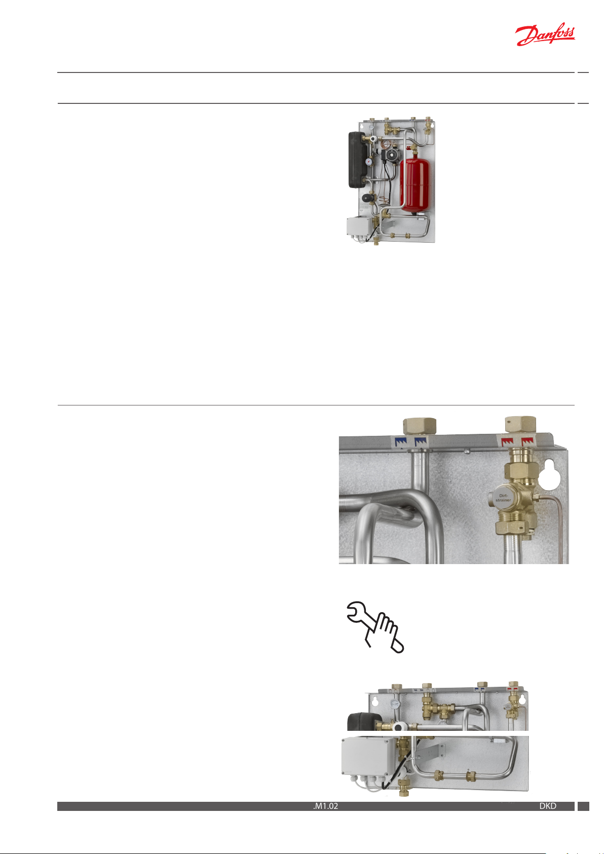
VX Solo HWS, thermostatic control
1 HE circuit + secondary connection for DHW cylinder
VX Solo HWS, thermostatic control
1 HE circuit + secondary connection for DHW cylinder,
with cover
1. Contents
1.0 Contents .......................................................................................................................................................................................................................................2
2.0 Product introduction ............................................................................................................................................................................................................... 3
2.1 VX Solo HWS (thermostatic control and terminal box) - 1 HE circuit + sec. connection for DHW cylinder .....................................3
3.0 Dimensional sketch / connections .....................................................................................................................................................................................4
4.0 Enduser instructions, General ..............................................................................................................................................................................................5
5.0 Enduser instructions, Adjustment and Setting .............................................................................................................................................................6
6.0 Installation instructions, Safety and Handling ...............................................................................................................................................................7
7.0 Installation instructions - Getting started ....................................................................................................................................................................... 8
8.0 Description of VX Solo HWS .................................................................................................................................................................................................9
9.0 Installation instructions, general ........................................................................................................................................................................................9
10.0 Commissioning and start-up, VX Solo HWS ................................................................................................................................................................ 13
10.1 Programmable room thermostat / DHW time controller TP9000 .............................................................................................................. 13
11.0 Domestic hot water cylinder ............................................................................................................................................................................................ 16
12.0 Maintenance ........................................................................................................................................................................................................................... 17
12.1 Maintenance schedule (recommendations) ...................................................................................................................................................... 18
13.0 Troubleshooting .................................................................................................................................................................................................................... 19
14.1 Troubleshooting - Heating ....................................................................................................................................................................................... 19
13.2 Troubleshooting - Domestic hot water ................................................................................................................................................................ 21
14.0 EU Declaration of Conformity .......................................................................................................................................................................................... 23
15.0 Commissioning Certicate ................................................................................................................................................................................................ 24
2
DKDHR VI.HE.M1.02 Danfoss District Energy
Page 3
Instructions for installation and use VX Solo HWS substations
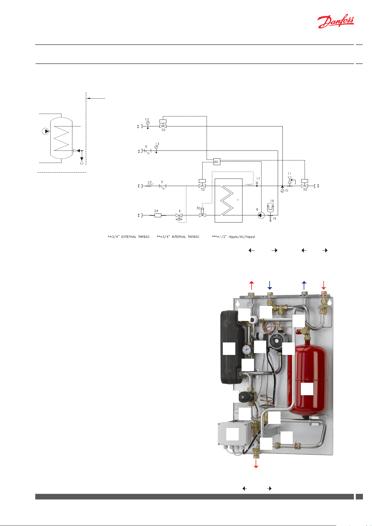
2.0 Product introduction
2.1 VX Solo HWS (thermostatic control and terminal box) - 1 HE circuit + sec. connection for DHW cylinder
Supply limit
Storage cylinder
Top:
Cylinder
supply
Common
return
Radiator return
DH
1 Plate heat exchanger, HE, insulated
4 Dierential pressure controller AVPL
5 Dirt strainer
8 Circulation pump, HE
11 Safety valve, HE 2.5 bar
13 Thermometer
14 Pocket for pressure gauge ¼
15 Manometer
16 Expansion vessel 12 L
supply
DH
return
Principal components
1 Plate heat exchanger HE
4 Dierential pressure controller
8 Circulation pump, HE
11 Safety valve HE
15 Manometer
16 Expansion vessel
17 Air valve
19 Fill valve
24 Fitting piece for heat meter
30 Thermostat Danfoss AVTB 30-100 °C
52 Zone valve Danfoss VMT/TWA-V
60 Terminal box
17 Air valve
19 Fill valve / Tapping point
23 Sensor pocket for heat meter ½“
24 Fitting piece for heat meter,
3/4” x 110 mm
30 Thermostat AVTB 30-100 °C
52 Zone valve Danfoss VMT/TWA-V
60 Terminal box
---------------------------------------------------
Terminal box is prepared for wiring of electronic
programmable room thermostat TP9000 for
heating or DHW operation according to demand.
Secondary
Common return
Cylinder supply
52
1 8
17
52
19
DH return
Bottom:
HE
Supply
Primary
DH supply
15
16
30
11
60
4
24
52
HE supply
Secondary
Danfoss District Energy VI.HE.M1.02 DKDHR
33
Page 4
Instructions for installation and use VX Solo HWS substations
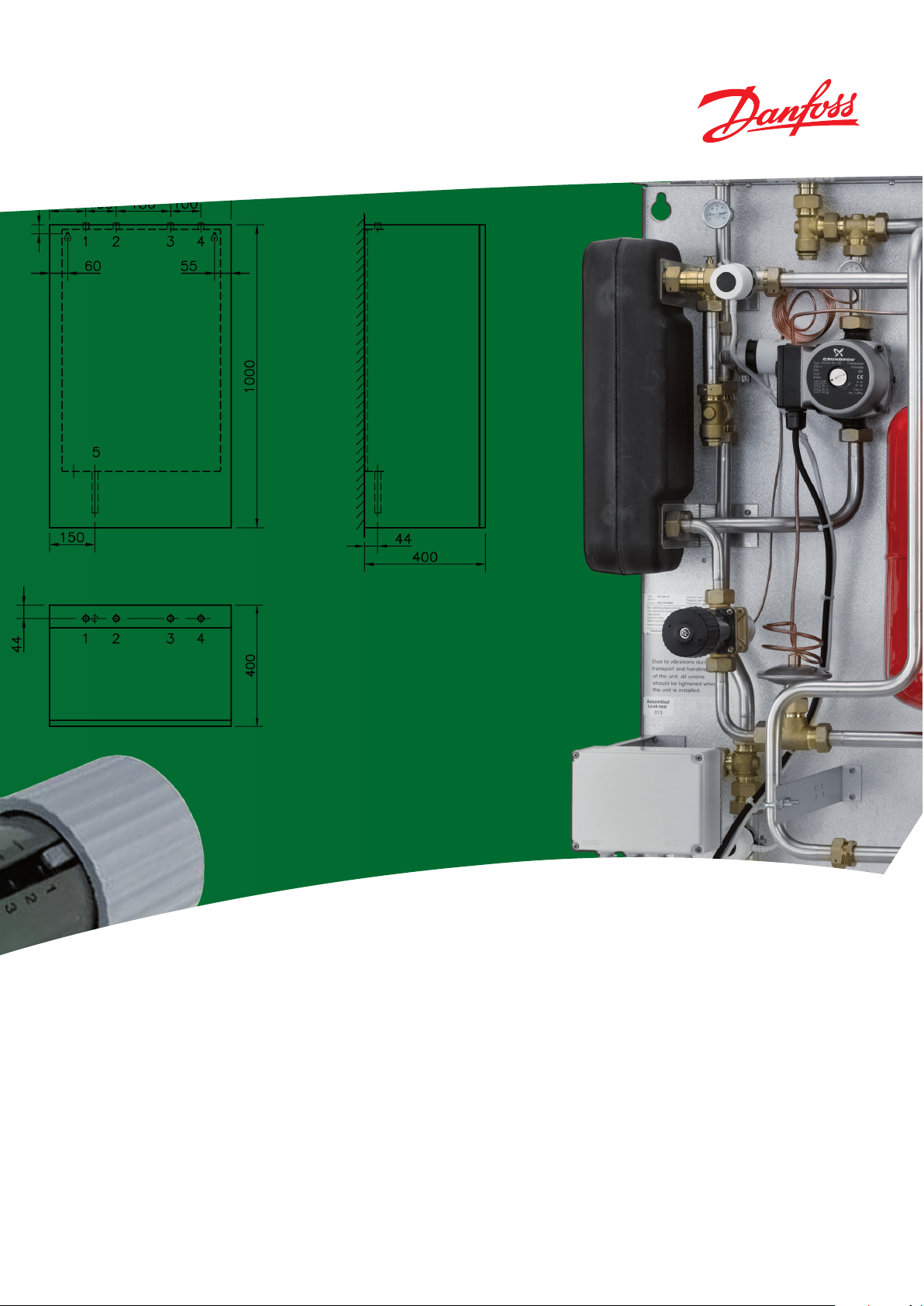
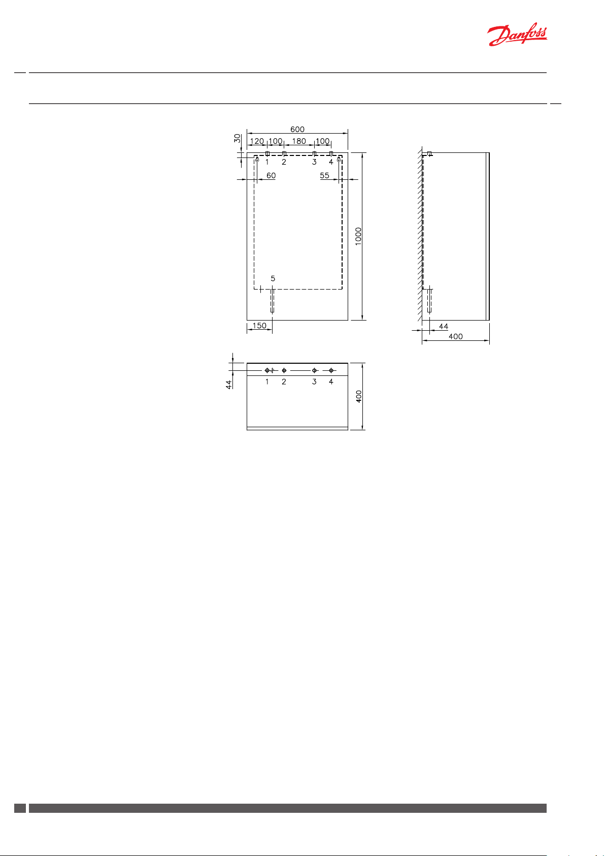
3.0 Dimensional sketch / connections
Dimensions:
Dimensions without cover
H 850 x W 560 x D 350 mm
Dimensions with cover
H 1000 x W 600 x D 400 mm
Connections:
Order:
1 Cylinder (DHW) supply
2 Common return
3 District heating (DH) return
4 District heating (DH) supply
5 Heating (HE) supply
Connections size:
DH: G¾” (IT)
HE: G¾” (IT)
Cylinder: G¾” (IT)
Zirk.
Wall
top view
4
DKDHR VI.HE.M1.02 Danfoss District Energy
Page 5
Instructions for installation and use VX Solo HWS substations
4.0 Enduser instructions, General
Instructions
Please read these instructions carefully before installing and commissioning this substation. The manufacturer accepts no liability for loss
or damage resulting from failure to comply with these instructions
for use. Read and follow these instructions carefully to prevent the
risk of physical injury and/or damage to property. Exceeding the
recommended operating parameters appreciably increases the risk
of personal injury and/or damage to property.
Warning! Hot surfaces
Parts of the substation may be very hot and can cause burn injuries. Be very careful when you are in the immediate vicinity of
the unit.
Installation, commissioning and maintenance must be carried out
by qualied and authorised personnel (both plumbing and electrical work).
Once the station has been installed and is operating, there is nor-
mally no need to alter the settings or other functions. The district
heating substation is very reliable and easy to operate.
If necessary, you can change the temperature settings as described
on page 6. For more detailed information about the substation,
see the sections concerning installation and commissioning.
Description
These instructions apply to substation type VX Solo HWS, which is
a district heating substation for indirect heating for single-family
houses, semi-detatched and terraced houses as well as ats. With
one heating circuit for radiator and/or oor heating and with connection pipes for domestic hot water cylinder on secondary side.
For wall-mounting.
The HE supply temperature is controlled by a self-acting temperature
controller Danfoss AVTB.
An immersion control thermostat of your choice choice, used to
control the water temperature in the hot water cylinder, must be
mounted on site.
As optional supply, Danfoss oers an immersion control thermostat
type ITC, which must be ordered separately and supplied loose together with the substation for mounting on site.
The ITC must be mounted in the 2/3 point of the DHW cylinder.
Warnings about high pressure and high temperature
The maximum supply temperature in the district heating network can be up to 110°C and the operating pressure can be up
to 16 bar. This may result in a risk of scalding from touching the
substation and from outow of the medium (water/steam). Exceeding the substation design data and operating parameters for
pressure and temperature carries an appreciable risk of personal
injury and/or damage to property.
Emergencies
In the event of re, leaks or other hazards, immediately shut o
all sources of energy to the substation, if possible, and call for
appropriate assistance.
If the domestic hot water is discoloured or malodorous, shut o
all ball valves on the substation and the storage cylinder, notify
all users and call for professional assistance without delay.
The VX Solo HWS is specicly prepared for connection of a TP9000
programmable room thermostat / DHW time controller, which allows
heating and DHW operation according to demand. The integrated
room thermostat will open/close the zone valve for heating operation and the DHW sensor in the cylinder or the DHW timer will open/
close the zone valve for DHW operation.
We recommend regular inspections of the substation - ideally in
connection with readings of the district heating meter.
Pay special attention to any leaks and an excessively high return
temperature in the district heating circuit (poor cooling of the district
heating water). Cooling – i.e. the dierence between the supply and
return temperature of the district heating water – has a signicant effect on the overall energy economy. Therefore, it is important to focus
on the supply and return temperature in the heating system.
The dierence should typically be 30–35°C in systems that operate
with radiators.
Irregularities
When reading the meters, check all joints and connections for leaks.
Check the troubleshooting section before contacting your professional provider.
Danfoss District Energy VI.HE.M1.02 DKDHR
55
Page 6
Instructions for installation and use VX Solo HWS substations
5.0 Enduser instructions, Adjustment and Setting
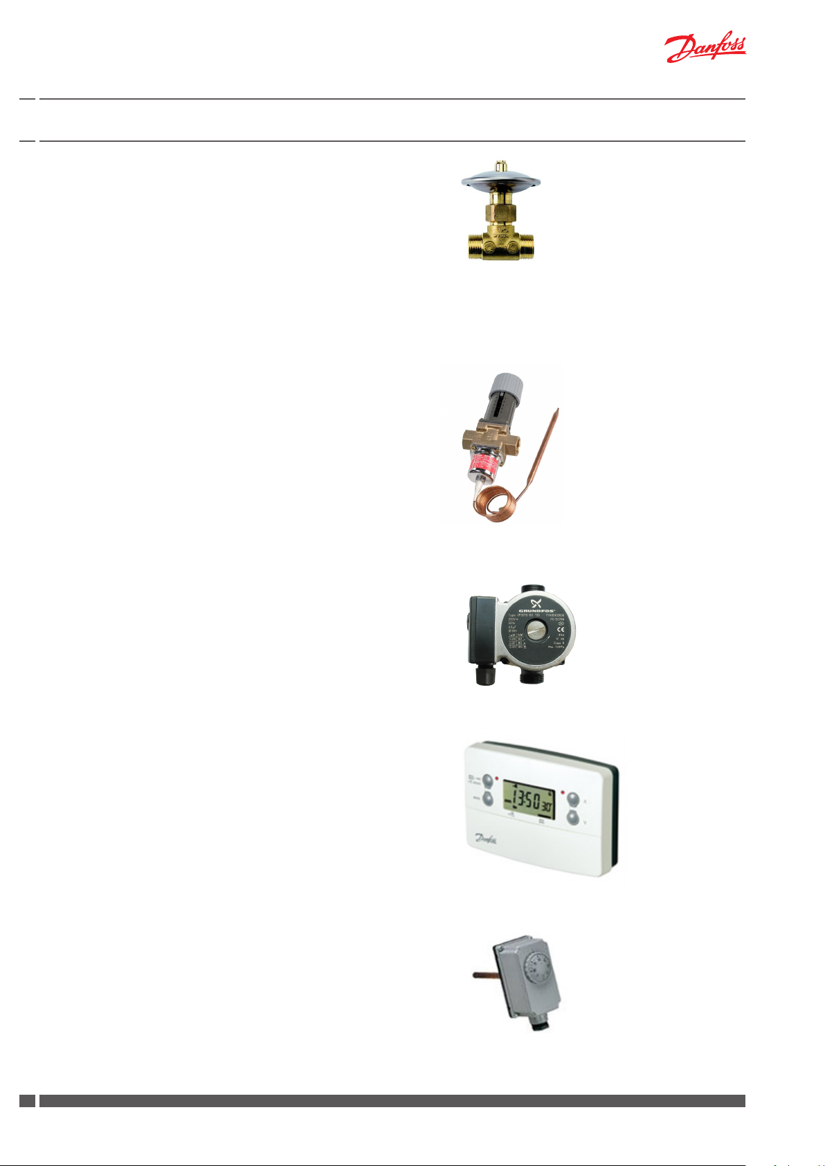
Heating circuit, Dierential Pressure Controller
The dierential pressure controller (Fig. 1) reduces the high, uctuating pressure in the district heating network to a constant operating
pressure.
The TD200 dierential pressure controller is preset from factory and
should not be adjusted afterwards.
Heating circuit, Temperature control
Thermostatic control
The HE temperature is controlled by a self-acting temperature controller Danfoss AVTB (Fig. 2). The controller has a control valve, thermostatic
actuator and handle for temperature setting.
The thermostat will be set by the installer in connection with the commissioning, but it may be necessary to adjust it subsequently depending on the outdoor temperature.
Approximate thermostat scale settings:
1.0 = 35 °C
1.5 = 45 °C
2.0 = 55 °C
2.5 = 65 °C
3.0 = 75 °C
The setting values may vary depending on the operating conditions.
It is important to set the supply temperature to the radiators as low
as possible. Use the radiator thermostat to regulate the room temperature.
Other variations with other types of thermostatic valves for control of
the heating circuit may occur.
Fig. 1
TD200
Fig. 2
AVTB
Pump.
VX Solo HWS substations are factory tted with a pump (Fig. 3). The
pump setting is established in connection with the commissioning.
Generally speaking, this setting is not to be altered. If it should nevertheless be necessary to change the pump setting, see the section concerning pumps in the installation and commissioning sections regarding the
individual products.
Programmable Room thermostat / DHW time controller
TP9000
The VX Solo HWS is specicly prepared for connection of a TP9000
controller (Fig. 4), which allows heating and DHW operation according to demand.
The TP9000 comes with a factory preset clock with automatic summer/winter time changes, and at installation the TP9000 is set to
operate in either full 7 day, 5 day/2 day mode, which allows dierent
programmes to be set for the weekend, or in 24 hour mode, in which
case the programmed events are repeated every 24 hours.
There is normally no need to alter the settings or other functions. However, should this be necessary, we recommend that you contact your
professional provider, or refer to separate instructions for TP9000.
Immersion Control Thermostat (mounting on site)
An applicable immersion control thermostat of your choice choice
must be mounted in the 2/3 point of the DHW cylinder.
An immersion control thermostat oers secure immersion sensing,
and is used to control water temperature in the hot water cylinder.
Fig. 3
Fig. 4
Fig. 5
As optional supply, Danfoss oers an immersion control thermostat
type ITC (Fig. 5), which must be ordered separately and supplied
loose with the substation for mounting on site.
The immersion thermostat has a 100mm insertion length and is supplied with a ½”BSP/100mm pocket. It has an adjustment range of
0-90°C has SPDT contact.
Recommended setting is 60 °C.
6
DKDHR VI.HE.M1.02 Danfoss District Energy
Immersion Control Thermostat ITC for
cylinder - 132.886 - Code No. 099-1057
Page 7
Instructions for installation and use VX Solo HWS substations
6.0 Installation instructions, Safety and Handling
Instructions
Please read these instructions carefully before installing and comissioning this substation. The manufacturer accepts no liability for loss or
damage resulting from failure to comply with these instructions for use.
Read and follow these instructions carefully to prevent the risk of physical injury and/or damage to persons and property. Exceeding the recommended operating parameters considerably increases the risk of
personal injury and/or damage to property.
Installation, commissioning and maintenance must be carried out by
qualied and authorized personnel in compliance with the local safety
regulations.
Connection
It must be possible to cut o all energy sources to the unit - including electrical connections - at all times.
Warning! Hot surfaces
Parts of the substation may be very hot and can cause burn injuries. Be very careful when you are in the immediate vicinity of the
substation.
Once the station has been installed and is operating, there is normally
no need to alter the settings or other functions. The district heating
substation is very reliable and easy to operate.
Energy source
The substation is primarily designed for connection to district heating.
Alternative energy sources can be used if the operating conditions are
equivalent to district heating at all times.
Application
The substation is designed only to operate with water or a water-glycol
mixture (up to 40%), and other heating media may not be used.
The substation is to be connected to the household piping in a frost-free
room, where the temperature does not exceed 50 °C and the relative
humidity is not higher than 80%. The substation must no be covered,
bricked in or otherwise cut o from access.
Choise of materials
Only use materials, that comply with local regulations.
Corrosion
The maximum chloride compounds of the medium must not be higher
than 300 mg/l. The risk of corrosion increases considerably if the recommended chloride content is exceeded.
Safety valve(s)
Installation of safety valve(s) must always be in compliance with local
regulations.
Noise level.
≤ 55 dB.
Warning of high pressure and high temperature
The maximum supply temperature in the district heating network
can be up to 110°C and the operating pressure can be up to 16 bar.
This may result in a risk of scalding from touching the substation
and from outow of the medium (water/steam). Exceeding the
substation design data and operating parameters for pressure and
temperature carries an appreciable risk of personal injury and/or
damage to property.
Emergencies
In the event of re, leaks or other hazards, immediately shut o all
sources of energy to the substation, if possible and call for appropriate assistance.
If the domestic hot water is discoloured or malodorous, shut o all
ball valves on the substation, notify all users and call for professional
assistance immediately.
Warning of damage during transport
On reception of the substation, and before installing it, check for
any evidence of damage during transport.
The substation must be handled and moved with the greatest care
and attention.
NB! - Tightening of connections
Before mounting of the substation, ALL pipe connections MUST
be retightened, as vibrations during transport may have caused
leaks. Once the substation has been put into operation ALL pipe
connections MUST be pressure tested for leaks and retightened
once more if necessary.
DO NOT OVERTIGHTEN THE PIPE CONNECTIONS – see page 9,
“Test & connections” for more information.
Storage
Before installation, the units must be stored in a dry, heated (i.e. frostfree) room.
(Relative humidity max. 80% and storage temperature 5-70 °C).
The units must not be stacked higher than the limit at the factory (max.
8 layers) Units supplied in cardboard packaging must be lifted using the
handles incorporated in the packaging. Units must be placed on pallets
for transport/moving across large distances.
As far as possible, do not lift the substation by the pipes. Lifting by the
pipes may cause leaks. REMEMBER to retighten.
Disposal
Dispose of the packaging in accordance with the local regulations for
disposal of used packaging materials.
The substation is made of materials that cannot be disposed of together
with household waste.
Close all energy sources and disconnect all connection pipes. Disconnect
and dismantle the product for disposal in accordance with the applicable
local regulations for the disposal of the individual components.
Danfoss District Energy VI.HE.M1.02 DKDHR
Handling
We recommend that you wear suitable safety footwear while
handling and installing the substation.
77
Page 8
Instructions for installation and use VX Solo HWS substations
7.0 Installation instructions - Getting started
Connect the substation to the household piping in accordance with
the labelling at the bottom/top and/or in accordance with the instructions in this manual.
Commissioning:
1. The substation is prepared for wall mounting. Mount the substation on a solid wall using two sturdy bolts, screws, expansion bolts or similar.
2. Mount immersion control thermostat (either type ITC, which can
be supplied loose from Danfoss as an option or any other applicable thermostat) and wire this to the terminal box according to
wiring diagram on page 11.
3. Mount programmable controller TP9000 (to be ordered separately) and wire this to the terminal box according to wiring diagram
on page 11.
4. Close all shut-o valves (to be ordered separately) on the substation before connecting it/them to the household piping.
5. Mount the district heating meter (see page 10).
6. IMPORTANT! Tighten all pipe connections, as they may have
loosened during transport and handling.
7. On systems that feature a safety valve, establish a drain connection in compliance with the applicable legislation.
8. Fill the heat exchanger/ the system with water according to the
instructions on page 12 until the manometer shows a working
pressure, which corresponds to the system height + approx. 5
m (approx. 1.2 - 1.5 bar).
9. Check the substation and the household piping thoroughly
for leaks.
10. Pressure test the entire system for leaks in accordance with
the applicable regulations.
11. Connect the terminal box to the electricity supply, but do not
switch on the power.
12. Heat the system and vent the radiator circuit/heating side
thoroughly on the radiators and the air valve, if any.
13. Remove the red split on the position indicator of the zone
valve.
14. Now switch on the power.
15. Finish by adjusting the substation in accordance with the
instruction manuals.
Heating and cooling the substation may cause leaks. Therefore
it may be necessary to retighten the connections in the period
after commissioning.
8
DKDHR VI.HE.M1.02 Danfoss District Energy
Page 9
Instructions for installation and use VX Solo HWS substations
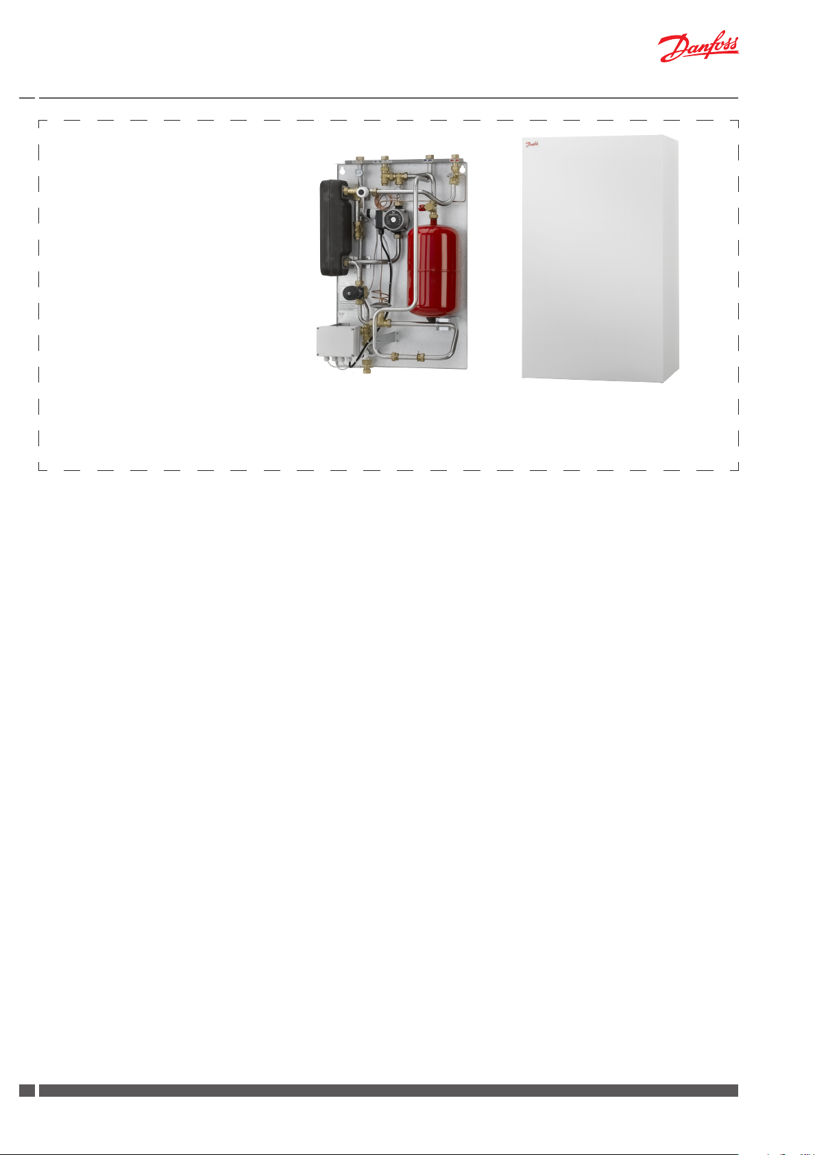
8.0 Description of VX Solo HWS
Substation for indirect heating for single-family, semi-detatched
and terraced houses as well as ats. With one heating circuit for radiator or oor heating and with connection pipes for domestic hot
water cylinder on the secondary side. For wall-mounting.
The temperature for the heating circuit is controlled by a self-acting
temperature controller Danfoss AVTB.
An applicable immersion control thermostat of your choice, used
to control the water temperature in the hot water cylinder must be
mounted on site.
Danfoss oers an immersion control thermostat type ITC, which must
be ordered separately and supplied loose with the substation for
mounting on site.
The substation is prepared for mounting of a programmable TP9000
controller, which allows heating and DHW operation according to
demand. The integrated room thermostat will open/close the zone
valve for heating operation and the DHW sensor in the cylinder or
the DHW timer will open/close the zone valve for DHW operation.
Please note:
Your substation may look dierent than the substation shown, as variants with other components may be supplied.
Supplier instructions for the tted components will always be supplied
together with the substation.
9.0 Installation instructions, general
Installation
The installation, connection and maintenance of the substation must
be performed by qualied and authorised personnel.
Installation must always be performed in accordance with the applicable legislation and in compliance with these instructions.
The substation must be installed so that it is freely accessible and can
be maintained without unnecessary disruption. Lift the substation
by its mounting plate and secure it to a solid wall using 2 sturdy
bolts, screws or expansion bolts positioned in the two keyholes in
the mounting plate.
Before commissioning, rinse all the pipes in the household piping
system thoroughly to remove any impurities, and check and clean
the dirt strainers in the substation.
Connect the substation to the household piping in accordance with
the labelling at the bottom/top and/or in accordance with the instructions in this manual.
Test and connections
Before lling the system with water, retighten all the pipe connections
because vibrations and shocks during transport and handling may
have caused leaks. Once the system has been lled with water, tighten
all the pipe connections once more before performing pressure test
for leaks. After heating of the system, check all the connections and
retighten if necessary.
Please note that the connections feature EPDM rubber gaskets!
Therefore, it is important that you DO NOT OVERTIGHTEN the union
nuts. Over-tightening may result in leaks. Leaks caused by overtightening or failure to retighten connections are not covered by
the warranty.
Connections
Connection of pipes for DH supply and return, common return as well
as DHW cylinder is established in top of the substation, and connection of pipe for HE supply is established in bottom of the substation.
Danfoss District Energy VI.HE.M1.02 DKDHR
99
Page 10

Instructions for installation and use VX Solo HWS substations
Expansion vessel
The VX Solo HWS substation is equipped with an expansion vessel,
which is factory set to 0,5 bar.
Fitting piece for heat meter(s)
The VX Solo HWS substation is equipped with xed tting piece size
3/4” x 110 mm for tting of heat meter in DH return.
Fitting of heat meters
- Close the ball valves on the district heating and the heating
sides.
- Loosen the union nuts at both ends of the tting piece and
remove it.
- Fit the heat meter, - remember to insert gaskets.
- Mount sensor, - remember to insert gaskets.
- After mounting of heat meter remember to check and tighten
all pipe connections before commissioning the heat meter.
The heat meter is to be installed so that the direction of ow corresponds to the direction of the arrow on the ow sensor.
Mounting of temperature sensor
As standard the heat meter is supplied with temperature sensors for
measuring the supply and return ow temperatures.
The VX Solo HWS substation is prepared for mounting of temperature
sensors with M10x1 connection (see photo to the right).
The supply ow sensor is mounted in the sensor pocket on DH supply (pos. A)
- demount M10 plug (pos. A)
- insert one temperature sensor in the sensor pocket
- tighten temperature sensor union nut
Mount the return ow sensor in the heat meter housing (pos. B).
A
A
Pipe bushing ½”/M10x1 incl. plug M10
B
10
DKDHR VI.HE.M1.02 Danfoss District Energy
Page 11

Instructions for installation and use VX Solo HWS substations
Electrical connection
The VX Solo HWS substation is wired and tested in the factory, and
internal electrical components are pre-wired into an electrical terminal box.
The electrical connection of the substation must be performed by a
qualied and authorised electrician in compliance with all applicable
rules and regulations.
The station should be connected to a 230 V AC power supply.
The power supply / connection must be carried out in accordance
with the applicable regulations and instrustions.
The station must be connected to an external main switch so that it
can be disconnected during maintenance, cleaning and repairs or
Electrical terminal box
The electrical terminal box houses the internal electrical connections
of the substation and allows the wiring in the substation to interface
with the main power supply provided by a local utility.
For the VX Solo HWS with terminal box, the pump and zone valve are
pre-wired to the terminal box, and the terminal box is also prepared
for connection of a TP9000 programmable room thermostat / DHW
time controller and a ITC immersion control thermostat.
Thermal actuator TWA-V
Supply voltage 230 V a.c. - 50-60 Hz
Protection class: IP41
Power consumption Average 2 Watt
For further information please refer to the enclosed instructions.
Pump Grundfos UPS 15-60
Supply voltage: 230 V a.c. - 50 Hz
Protection class: IP44
Power consumption: Max. 100 Watt
For further information please refer to the enclosed instructions for
the circulation pump.
See below wiring diagram for more information.
Danfoss District Energy VI.HE.M1.02 DKDHR
1111
Page 12

Instructions for installation and use VX Solo HWS substations
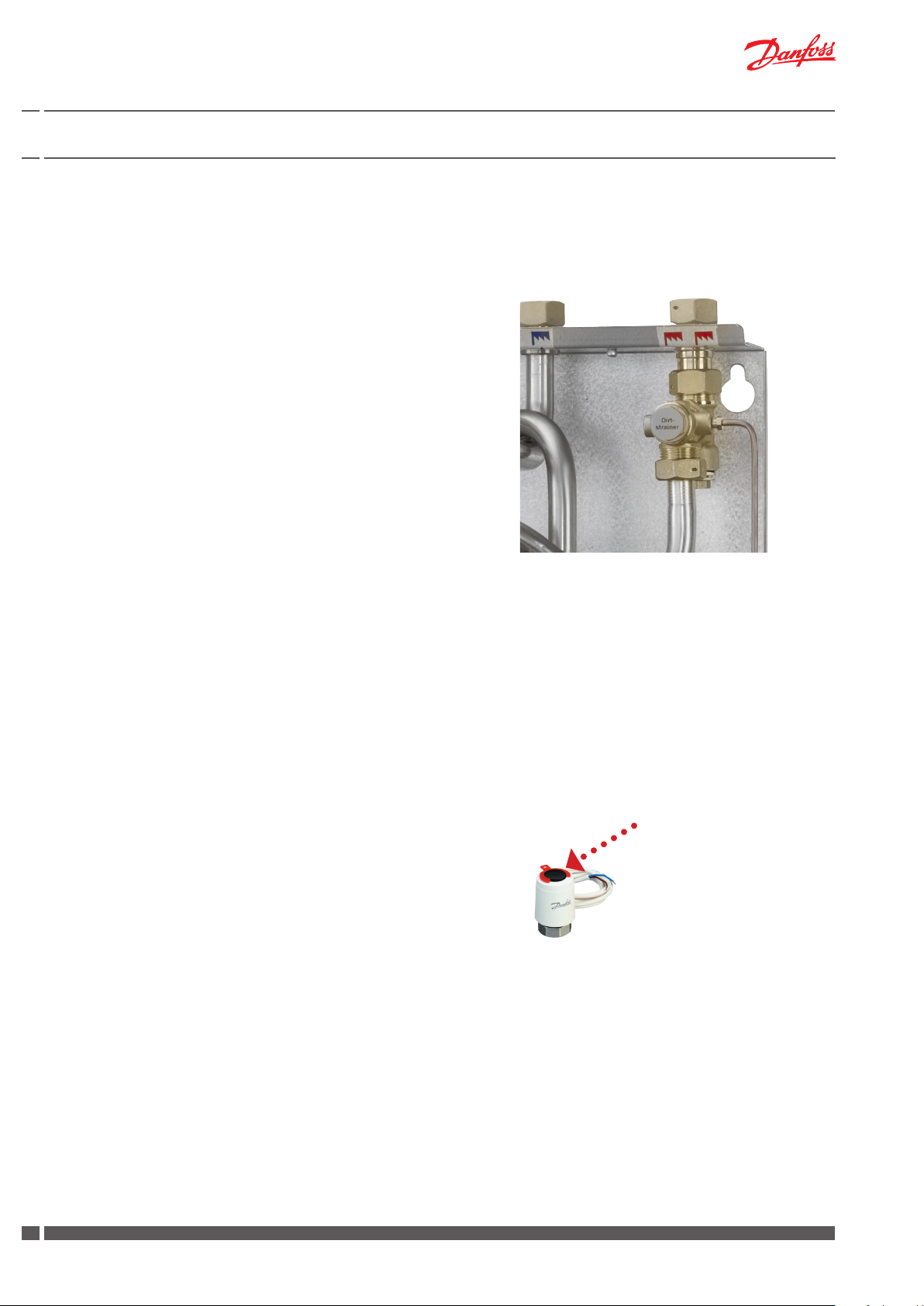
Filling, start-up
Prior to the VX Solo HWS installation all its pipes and connections
should be cleaned and rinsed. After that the dirt strainers should
be cleaned.
Due to vibrations during transport all connections must be checked
and tightened before lling and start-up.
Before starting-up, check if:
- pipes are connected according to the circuit diagram,
- expansion vessel is connected,
- heat meter is mounted,
- shut-o valves (to be ordered separately) are closed,
- threaded and anged connections are tightened.
The pump must be switched o when lling the system with water.
• Open the ball valves for the HE supply and return ow as well
as the ball valve for DCW (ball valves to be ordered separately).
• Carefully open the ll valve and ll the system with water and
at the same time vent the system.
• Fill the heat exchanger / the system with water* until the manometer shows a working pressure, which corresponds to the
system height + approx. 5 m (approx. 1.2 - 1.5 bar).
Fill valve
• Close the ll valve.
• Finally open the remaining ball valves (to be ordered separate-
ly) and heat up the system.
• Remove the red split on the position indicator of the zone
valve.
• After lling and heat-up of the system it should be vented by
means of the air vents on the substation, if any and on the ra-
Manometer and lling
If the pressure drops below 1 bar, water must be added to the system.
The operating pressure should never exceed 1.5 bar.
(The safety valve opens at 2,5 bar)
If system pressure drops dramatically within a short time, heating
system should be examined for leakage, - this includes checking
the factory set pressure of the expansion vessel.
12
DKDHR VI.HE.M1.02 Danfoss District Energy
Page 13

Instructions for installation and use VX Solo HWS substations
10.0 Commissioning and start-up, VX Solo HWS
10.1 Programmable room thermostat / DHW time controller TP9000
TP9000 (not part of delivery)
A programmable room thermostat / DHW time controller TP9000,
which allows heating and DHW operation according to demand,
must be placed in a reference room.
The integrated room thermostat will open/close a zone valve for
heating operation, and the DHW sensor in the cylinder or the DHW
timer will open/close the zone valve for DHW operation.
When there is no demand for heating or DHW all zone valves primary
and secondary are closed. And pump P1 is not running.
When the room thermostat calls for heating the primary zone valve M1
and the secondary zone valve M3 will open. Pump P1 will be switched
on. Zone valve M2 for DHW will remain closed.
When there is no heat demand all zone valves will close. And pump
P1 is not running.
When the sensor in the DHW cylinder calls for demand or the DHW
timer calls for demand the primary zone valve M1 will open, and secondary zone valve M2 will open and secondary zone valve M3 will close.
Pump P1 will then be switched on.
MAKING MODERN LIVING POSSIBLE
M1
Electronic Programmable Room Thermostat
Danfoss Heating
TP9000
plus Domestic Hot Water Timer
Installation Guide
Zone valves / thermal actuators TWA-A
Heating and DHW operation is activated by the programmable room
thermostat / DHW time controller TP9000 in connection with a zone
valve /thermal actuator TWA-A.
The thermal actuators of the zone valves are switched on by an external contact from the room thermostat, and start to open or close
the valves. The actuating movement is achieved by means of an
electrically heated expansion element. When the heating current is
switched o, the actuators shut or open the valves.
The actuators are equipped with a visual position indicator to show
the open or closed position of the valves.
INSTRUCTIONS
TWA NC
TWA-A
For Danfoss RA valves
TWA-V
For Danfoss RAV/VMT valves
TWA-L
For Danfoss RAVL valves
TWA-K
For Heimeier/MNG/Oventrop
valves with M30 × 1.5 connection,
generally as per attached drawing.
Other valves must be veried
individually to ensure correct
valve closing measurement and
valve top geometry.
TWA-D
For Danfoss RTD valves
P1
M2
M3
*) 24 V Class II transformer (SELV)
**) 230 V max. 3 A pre-fuse
VI.SB.H3.02 12-2005 Produced by Danfoss Industri Service 05.09 JJ-Bi.DS
088R0248| 15.12.2005 | Version 03
Thermal actuator TWA-A
Danfoss District Energy VI.HE.M1.02 DKDHR
1313
Page 14

Instructions for installation and use VX Solo HWS substations
Dierential pressure controller
(Standard on systems with self-acting thermostatic valve).
The dierential pressure controller reduces the uctuating
pressure in the district heating network to a small and invariable
operating pressure in the substation.
The required room temperature is controlled on your radiator thermostats.
Dierential pressure controller TD200
A diferential pressure controller type TD200 is mounted in the substation.
TD200 is a self-acting dierential pressure controller, which is preset
from factory and it is not possible to adjust it afterwards.
TD200
Control of heating circuit
The HE temperature is controlled by a self-acting temperature controller Danfoss AVTB. The controller has a control valve, thermostatic
actuator and handle for temperature setting.
The AVTB closes on rising temperature.
The thermostat will be set by the installer in connection with the commissioning, but it may be necessary to adjust it subsequently depending on the outdoor temperature.
Setting changes:
Turning the handle counterclockwise increases the temperature, turning it clockwise reduces the temperature. The scale is graduated with
reference values, i.e. the temperature cannot be read from the scale,
but must be read from a thermometer placed near the sensor in the
medium to be temperature-controlled.
Approximate thermostat scale settings:
1 = 35 °C
2 = 55 °C
3 = 75 °C
4 = 95 °C
5 = 120 °C
INSTRUCTIONS
AVTB with sensor Ø9.5/180 mm
003R9157
DANSK ESPANOL
AVTB-ventiler med lille/lang føler
Las válvulas AVTB con sensor
(∅9,5/180 mm) skal monteres i retur-
pequeño/largo (∅9,5/180 mm) deben
montarse en la línea de retorno (el
ledningen (føleren skal placeres varmere end det medie der gennemstrøm-
sensor debe montarse en un lugar que
mer ventilen).
sea más caliente que el medio que
fluye por la válvula).
Hvis AVTB, med temperaturområdet 20-
Si la válvula AVTB con gama de tempe-
60 °C, monteres forkert, så føleren
ratura de 20-60 °C se monta
bliver koldere end AVTB-regulatorens
incorrectamente, de manera que el
ventil-hus, vil regulatoren holde op med
sensor esté más frío que el cuerpo de
at regulere.
válvula del regulador AVTB, el
ENGLISH
regulador dejará de regular.
AVTB valves with small/long sensor
ITALIANO
(∅9.5/180 mm) must be fitted in the
return line (sensor placed warmer than
La valvola AVTB con il bulbo piccolo/
the medium flowing through the valve).
lungo (∅9,5/180 mm) deve essere
montata nel tubo di ritorno (il bulbo deve
If AVTB with 20-60 °C temperature
essere più caldo del fluido che
range is installed incorrectly so that the
attraversa la valvola).
sensor becomes colder than the valve
body, the valve will stop regulating.
Se la valvola AVTB con campo di
regolazione da 20°C a 60°C viene
DEUTSCH
erroneamente montata con il bulbo più
Das Ventilgehäuse des
freddo del corpo valvola, la regolazione
Temperaturreglers AVTB mit kleinem/
del flusso non avviene.
langen Fühler (...) ist in die
Rücklaufleitung einzubauen (der
Einbauort des Fühlers muß wärmer
SVENSKA
sein, als der des Ventilgehäuses).
AVTB-ventiler med liten/lång givare
Durch einen falschen Einbau (der
(∅9,5/180 mm) skall monteras i retur-
Einbauort des Fühlers ist kälter als der
ledningen (givaren skall placeras
des Ventilgehäuses) des AVTB mit dem
varmare än det medium, som genom-
Temperaturbereich 20-60°C ist die
strömmar ventilen).
einwandfreie Funktion des Reglers nicht
gewährleistet.
Om AVTB, med temperaturområdet 20-
FRANCAIS
60° C, monteras fel, så att givaren blir
kallare än AVTB-regulatorns ventilhus,
Les vannes AVTB avec sonde mince et
kommer regulatorn att upphöra med att
longue (∅9,5/180 mm) doivent se
reglera.
monter sur le tube de retour (la sonde
doit être placée à un endroit plus chaud
que le fluide qui traverse la vanne).
Si une AVTB ayant une échelle de
température de 20 à 60 °C est mal
montée (la sonde devient plus froide
que le corps de vanne du régulateur de
l’AVTB), ce régulateur va cesser de
fonctionner.
BC-HM VI.5A.A1.5R © Danfoss 09/00 1
NEDERLANDS
AVTB-afsluiters met een smalle/lange
voeler (o 9,5/180 mm) moeten in de
retourleiding gemonteerd worden (de
temperatuur van de voeler dient
warmer te zijn dan van het medium dat
door de afsluiter stroomt).
Bij een AVTB met een
temperatuurbereik van 20-60°C dient
tijdens bedrijf de temperatuur van de
voeler altijd warmer te zijn dan het
afsluiterhuis. Indien dit niet zo is stopt
de werking van de regelaar.
SUOMEKSI
Käytettäessä pientä/pitkää anturia
(∅9,5/180 mm) on AVTB-venttiili aina
asennettava paluujohtoon (anturi on
sijoitettava siten, että sen lämpötila on
korkeampi kuin venttiilin läpi virtaavalla
aineella).
Jos AVTB-venttiili, jonka lämpötila-alue
on 20-60 °C, asennetaan virheellisesti
niin, että anturin lämpötila on
alhaisempi kuin AVTB-venttiilin rungon
lämpötila, säätimen toiminta lakkaa.
003R9157
AVTB
14
DKDHR VI.HE.M1.02 Danfoss District Energy
Page 15

Instructions for installation and use VX Solo HWS substations
UP, UPS, UPD, UPSD
GRUNDFOS INSTRUCTIONS
25
0.12
Type UPS 25-40 180
230V
50Hz
2 µF
35
45
0.16
0.20
DK
I
1/1
1
(A)
P
(W)
Max.1.0 MPa
P/N:96281384
PC:0528
IP 44
TF 110
E
nerg
i
y
a
e
A
B
C
D
E
F
G
984996
Circulation pump, heating circuit
The VX Solo HWS substation comes standard with a Grundfos UPS
15-60 circulation pump, which can be operated at three dierent
speeds.
A supplier instructions manual is enclosed.
Other variations with other types of circulation pump may occur and
in such cases supplier’s installation instructions for the specic pump
will be enclosed.
Substation start-up / pump
Do not start up the pump until the system has been lled with the
ow media and vented.
At start-up the rotor can is to be vented by removing the plug in
the top of the motor.
Pump setting
3 speeds allow to set up the circulator pump in a way, that matches the system’s requirements, while wet rotor design allows it to be
virtually silent while operating.
It is recommended to set the pump at highest speed of rotation
(setting 3) before start-up. Then set the pump at lowest possible
speed of rotation (setting 1), in due consideration of the lectricity
consumption and the heating comfort. Factory setting of the selector switch is centre position (default). Select setting 2 and 3 only
if the pump setting does not meet actual system requirements
For further information please refer to the enclosed Grundfoss instructions.
GRUNDFOS INSTRUCTIONS
UP, UPS
GRUNDFOS INSTRUCTIONS
UP, UPS
Danfoss District Energy VI.HE.M1.02 DKDHR
1515
Page 16

Instructions for installation and use VX Solo HWS substations
11.0 Domestic hot water cylinder
Domestic hot water
The VX Solo HWS substation is supplied with connection pipes for
domestic hot water cylinder on the secondary side.
(Please note that cylinder control thermostat is to be ordered separately, - either type ITC, which can be supplied loose from Danfoss as
an option or any other compatible/applicable thermostat).
Option:
Immersion control thermostat
Danfoss oers an immersion control thermostat type ITC, which must
be ordered separately and then supplied loose with the substation
for mounting and wiring to the terminal box on site.
The thermostat has a 100 mm insertion lengt and is supplied with
a ½” BSP/100 mm pocket.
It has an adjustment range of 0 to 90 °C and has SPDT contacts.
Recommended setting is 60 °C.
Mounting of immersion control thermostat
1) Mount sensor pocket in cylinder.
2) Mount immersion thermostats in immersion pocket.
3) Wire the immersion thermostat cable in the terminal box
according to the wiring diagram on page 11.
Please see also refer to enclosed
Installation Instructions for ITC Immersion Thermostat
Installation Instructions
ITC, ITL & ITD Immersion Thermostats
ITC ITL ITD
Control Limit
Control
Limit
DHW operation
When the sensor in the DHW cylinder calls for demand or the DHW
timer calls for demand, DHW operation is activated by the programmable room thermostat / DHW time controller TP9000 in connection
with a zone valve /thermal actuator TWA-A.
See operation descriptions on page 13 for further information.
Thermal actuator TWA-ATP9000
16
DKDHR VI.HE.M1.02 Danfoss District Energy
Page 17

Instructions for installation and use VX Solo HWS substations
12.0 Maintenance
Maintenance work
Is only to be carried out by qualied and authorised personnel.
Inspection
The substation should be checked regularly by authorised personnel.
Any necessary maintenance must be performed in accordance with the
instructions in this manual and other sets of instructions.
During service the dirt strainers are to be cleaned – including the lter
on the controller, all pipe connections must be tightened and the safety
valve must be function tested by turning the lever.
Rinsing/cleaning of plate heat exchanger
To clean the plate heat exchanger, rinse it by running clean water
through the exchanger at high speed and in the opposite direction to
the normal ow. This will remove any dirt deposits that may have built
up in the exchanger. If rinsing with clean water is not sucient, the
exchanger can also be cleane d by circulating a cleaning agent approved
by Danfoss (e.g. Kaloxi or Radiner Fl cleaning uid) through the
exchanger. Both these cleaning uids are environmentally friendly and
can be disposed o through the standard sewer system. After use of
a cleaning uid, the plate heat exchanger must be rinsed thoroughly
with clean water.
Acid cleaning of plate heat exchanger
Deposits of limescale may build up in plate heat exchangers for domestic
hot water on account of the large temperature uc tuations, and because
aerated water is used on the secondary side. If it becomes necessary
to clean the exchanger with acid, this can be done as shown on the
drawing to the right. Brazed plate heat exchangers can withstand
rinsing with a dilute acid solution - e.g. 5% formic, acetic or phosphoric
acid).
Measures after maintenance work
After maintenance work and before commissioning:
– Check that all screwed connections are tight.
– Check that all safety features, covers, that were removed, have been
replaced properly.
– Clean the working area and remove any spilled materials.
– Clear all tools, materials and other equipment from the working area.
– Connect to energy supply and check for leaks.
– Vent the system.
– Carry out any necessary adjustment again.
– Make sure that all safety features on the device and the system work
properly.
Meter reading
The caretaker/owner must perform visual checking and reading of
the energy meter at short, regular intervals.
Service procedures must only be performed by trained, authorised
personnel.
NB! Excessive consumption for whatever reason is not covered by
the Danfoss warranty.
Cooling / Return temperature reading
Cooling – i.e. the dierence between the supply and return temperature
of the district heating water – has a signicant eect on overall energy
economy. Therefore, it is important to focus on the supply and return
temperature in the heating system. The dierence should typically be
30–35°C. Please note that a low district heating return temperature is
directly related to the return temperature from the heating circuit and
the return temperature of the circulation water.
It is therefore important to focus on these return temperatures.
Danfoss District Energy VI.HE.M1.02 DKDHR
1717
Page 18

Instructions for installation and use VX Solo HWS substations
12.1 Maintenance schedule (recommendations)
Interval Maintenance work Comments
Check all connections for leaks
Check that the safety valve on the cold water supply is
functioning correctly.
Check that all components are intact and functioning as
intended
Clean all dirt lters/strainers in the substation Replace any lters that are not intact
At least once a year
Check that any electrical cables are in serviceable condition
and that it is possible to disconnect the electrical power supply to the substation
Check the pipes and exchanger for signs of corrosion Visual check
Check that the temperature regulators are set in accordance
with the instructions in this manual
Check the functions of all shut-o valves Check that the ball valves open and close as they should
Service and maintenance procedures must only be performed by
trained, authorised personnel.
Please note that after dismantling, the gaskets MUST be replaced.
Once the system has been lled with water, retighten all the pipe
connections once more before performing pressure test for leaks.
After heating of the system, check all the connections and
retighten if necessary.
Please note that the connections may feature EPDM gaskets! Therefore,
it is important that you DO NOT OVERTIGHTEN the pipe
connections. Over-tightening may result in leaks. Leaks caused by
over-tightening or failure to retighten connections are not covered
by the warranty.
If you identify a leak, replace the gaskets and retighten the pipe connections
Check the functionality by turning the lever on the safety valves
In the event of irregularities, lack of functionality or visible faults and
defects in a component, replace the component in questionn
Visual check. Check whether it is possible to disconnect the current to the
substation.
Follow the instructions in the present manual
18
DKDHR VI.HE.M1.02 Danfoss District Energy
Page 19

Instructions for installation and use VX Solo HWS substations
13.0 Troubleshooting
If operating disturbances occur, the following basic features
should be checked before carrying out acual troubleshooting:
- the substation is correctly connected,
- the district heating supply temperature is at least 70 °C,
- the dierential pressure is higher than or equal to the normal
(local) dierential pessure in the district heating network. - If
in doubt, ask the district heating plant,
14.1 Troubleshooting - Heating
Problem Possible cause Solution
Strainer clogged on DH og HE side
(radiator circuit).
Filter in district heating meter clogged. Clean the lter (after consulting the
Defective dierential pressure controller. Check the functions of the dierential
Defective sensor Replace sensor
Defektive actuator. Check the functioning of the actuator.
Defective motor valve - or possibly dirt
in the valve housing.
No heat
Automatic controls wrongly set or defective - possibly power failure.
- the substation is connected to electricity (pump and
automatic components),
- the dirt strainer in the district heating supply pipe is clean,
- air pockets in the system.
Clean strainer.
district heating plant).
pressure controller - clean valve seat if
required.
Check the functions of the motor valve clean valve housing if required.
Check if the setting of the controller is
correct - see separate instructions. Check
the power supply.
Temporary setting of actuator to “manual” control - see instruction on heating
circuit, manual control.
Uneven heat distribution
Supply temperature too high
Pump out of operation.
The pump is set at too low speed of
rotation.
Air pockets in the system. Vent the installation thoroughly.
Air pockets in the system. Vent the installation thoroughly.
Wrong setting of automatic controls. Adjust automatic controls, see instruc-
Defective sensor. Replace sensor.
Defective controller. The controller does
not react as it is should in accordance
with the instructions.
Check that the pump is receiving power
and that it runs. Control that there is
no air in the pump housing - see pump
manual.
Set the pump at higher speed of rotation
- see instructions on heating circuit.
tions for automatic controls.
Call in automatic controls manufacturer
or replace controller.
Danfoss District Energy VI.HE.M1.02 DKDHR
1919
Page 20

Instructions for installation and use VX Solo HWS substations
Problem Possible cause Solution
Wrong setting of automatic controls.
Adjust automatic controls, see instructions for automatic controls.
Supply temperature too low
Poor cooling
Defective controller. The controller does
not react as it is should in accordance
with the instructions.
Outdoor sensor mounted or placed
incorrectly.
Strainer clogged. Clean strainer.
Too small heating surface/ too small
radiators compared to the total heating
requirement of the building.
Poor utilization of existing heating
surface.
The system is single-pipe. It is extremely important to keep the
Call in automatic controls manufacturer
or replace controller.
Mount/place outdoor sensor correctly.
Increase total heating surface.
Make sure that the heat is distributed
evenly across the full heating surface open all radiators and keep the radiator
in the system from heating up at the
bottom. Higher temperature at the top
and lower temperature at the bottom
part of the radiators means that the
system operation is correct.
supply temperature to the radiators as
low as ever possible, while maintaining a
reasonable level of comfort.
20
DKDHR VI.HE.M1.02 Danfoss District Energy
Page 21

Instructions for installation and use VX Solo HWS substations
13.2 Troubleshooting - Domestic hot water
Problem Possible cause Solution
No domestic hot water
Long waiting time
Defective or wrongly set dierential
pressure controller.
Strainer on DH supply clogged. Clean strainer.
Defective actuator - or possibly dirt in
the valve housing.
Automatic controls wrongly set or defective - possibly power failure.
Calied heating element. Clean DHW cylinder with acid solution or
Inadequate cylinder capacity. Wait for heating / loading of the cylinder.
Circulation pump out of operation. Check whether the pump is running -
Check the functions of the dierential
pressure controller - clean valve seat and
capillary tubes if required, - air and rinse
capillary tubes.
Check the functions of the actuator clean valve seat if required.
Check if the setting of the controller is
correct, - see separate instructions.
Check the power supply;
Temporary setting of actuator to “manual” control - see instructions on heating
circuit, manual control.
replace heating element.
You may check the specications of the
manufacturer conc. cylinder capacity.
whether the pump is receiving power.
control that there is no air in the pump
housing - see pump manual.
Temperature too low
Temperature too high
Variations in temperature
See “No domestic hot water”. See “No domestic hot water”.
Non-return valve on the circulation line
defective (leads to mixing - and the
circulation water pipes become cold during tapping).
Defective actuator - possibly dirt in the
valve housing.
Automatic controls wrongly set or defective.
Defective immersion sensor. Replace immersion sensor.
Non-return valve on the circulation line
defective (leads to mixing - and the
circulation water pipes become cold during tapping).
Replace non-return valve.
Check the functions of the actuator clean valve seat if required.
Check if the setting of the controller is
correct, - see separate instructions.
Replace non-return valve.
Danfoss District Energy VI.HE.M1.02 DKDHR
2121
Page 22

Instructions for installation and use VX Solo HWS substations
Problem Possible cause Solution
Declining temperature during tapping
Poor cooling
Defective or wrongly set dierential
pressure controller (set too low).
Automatic controls wrongly set. Check that the controller has been cor-
Immersion sensor placed incorrectly. Place immersion sensor correctly in ac-
Calied heating element. Clean DHW cylinder with acid solution or
Calied heating element. Clean DHW cylinder with acid solution or
Check the functions of the dierential
pressure controller - clean valve seat and
capillary tubes if required, - air and rinse
capillary tubes.
rectly set - see separate instructions.
cordance with the manufacturer instructions for the cylinder.
You may contact Danfoss Redan A/S for
further information.
replace heating element.
replace heating element.
You may check the specications of the
manufacturer conc. cylinder capacity.
22
DKDHR VI.HE.M1.02 Danfoss District Energy
Page 23

Instructions for installation and use VX Solo HWS substations
14.0 EU Declaration of Conformity
Danfoss Redan A/S
DK-8382 Hinnerup
Telephone +45 87 43 89 43
EC-DECLARATION OF CONFORMITY
For CE marking in EU (European Union)
Danfoss Redan A/S District Energy
DK-8382 Hinnerup
Declares under our sole responsibility that below products including all available power and control options:
VX Solo
Main components: See Instruction Manual
Covered by this declaration is in conformity with the following directive(s), standard(s) or other normative document(s), provided that the products are used in accordance with our instructions.
EU Directives:
EMC Directive 2004/108/EEC
EN 61000-6-1 2007
industry.
EN 61000-6-2 2005 Electromagnetic compatibility- Generic standard: Immunity industry.
EN 61000-6-3 2007 Electromagnetic compatibility- Generic standard: Emission for residential, commercial and light
industry.
EN 61000-6-4 2007 Electromagnetic compatibility- Generic standard: Emission industry.
Machinery Directive 2006/42/EEC
EN ISO 14121-
EN 60204-1-Safety of machinery - Electrical equipment of machines — Part 1: General requirements
PED Directive 97/23/EEC
Conformity assessment procedure followed: Module A - Internal control of production
All substations that falls under Article 3 §3 and category 1 shall not be CE-marked according to this directive
CE marked affixed year 2010
Approved by:
Place and date of issue: Hinnerup, Aug. 24th, 2010
Name: Thavarupan Perinpam
Title: Quality and Lean Manager
Electromagnetic compatibility- Generic standard: Immunity for residential, commercial and light
1 Safety of machinery -- Risk assessment
District Energy
Omega 7, Søften
Danfoss District Energy VI.HE.M1.02 DKDHR
2323
Page 24

Instructions for installation and use VX Solo HWS substations
15.0 Commissioning Certicate
Commissioning certicate
The substation is the direct link between the district heating supply network and the household piping system. All supply pipes and the
pipes in the household piping system must be checked and rinsed before commissioning. Once the system has been lled with water, all
pipe connections must be retightened before performing pressure test for leaks. The dirt strainers must be cleaned and the substation
must be adjusted in accordance with the instructions in this manual.
It is important to comply with all technical regulations and the applicable legislation in every respect.
Installation and commissioning must only be performed by trained, authorised personnel.
The substation is checked in the factory for leaks before delivery. Leaks are however possible due to vibrations caused by transport, handling and heating of the system and therefore it is important to check all connections and to retighten if necessarys before commissioning.
Please note that the connections may feature EPDM gaskets! Therefore it is important that you DO NOT OVER-TIGHTEN the connections.
Over-tightening may result in leaks. Leaks caused by ove-rtightening or failure to retighten connections are not covered by the warranty.
To be lled-out by the installer.
This substation has been retightened, adjusted and commissioned
on the: by installer:
Date/Year
Company name (stamp)
24
DKDHR VI.HE.M1.02 Danfoss District Energy
Page 25

Instructions for installation and use VX Solo HWS substations
Danfoss District Energy VI.HE.M1.02 DKDHR
2525
Page 26

Instructions for installation and use VX Solo HWS substations
26
DKDHR VI.HE.M1.02 Danfoss District Energy
Page 27

Instructions for installation and use VX Solo HWS substations
Danfoss District Energy VI.HE.M1.02 DKDHR
2727
Page 28

Danfoss Randall Ltd. · District Energy · Ampthill Road · DK-Bedford MK42 9ER
Tel. +0845 1217 400 · Fax: +0845 1217 515 · danfossrandall@danfoss.com · www.danfoss-randall.co.dk
VI.HE.M1.02
Produced by Danfoss Redan A/S © 04/2012
 Loading...