

Page 1
MAKING MODERN LIVING POSSIBLE
Danfoss District Energy
VX Solo 22
Instructions for installation and use
Page 2
Instructions for installation and use VX Solo 22
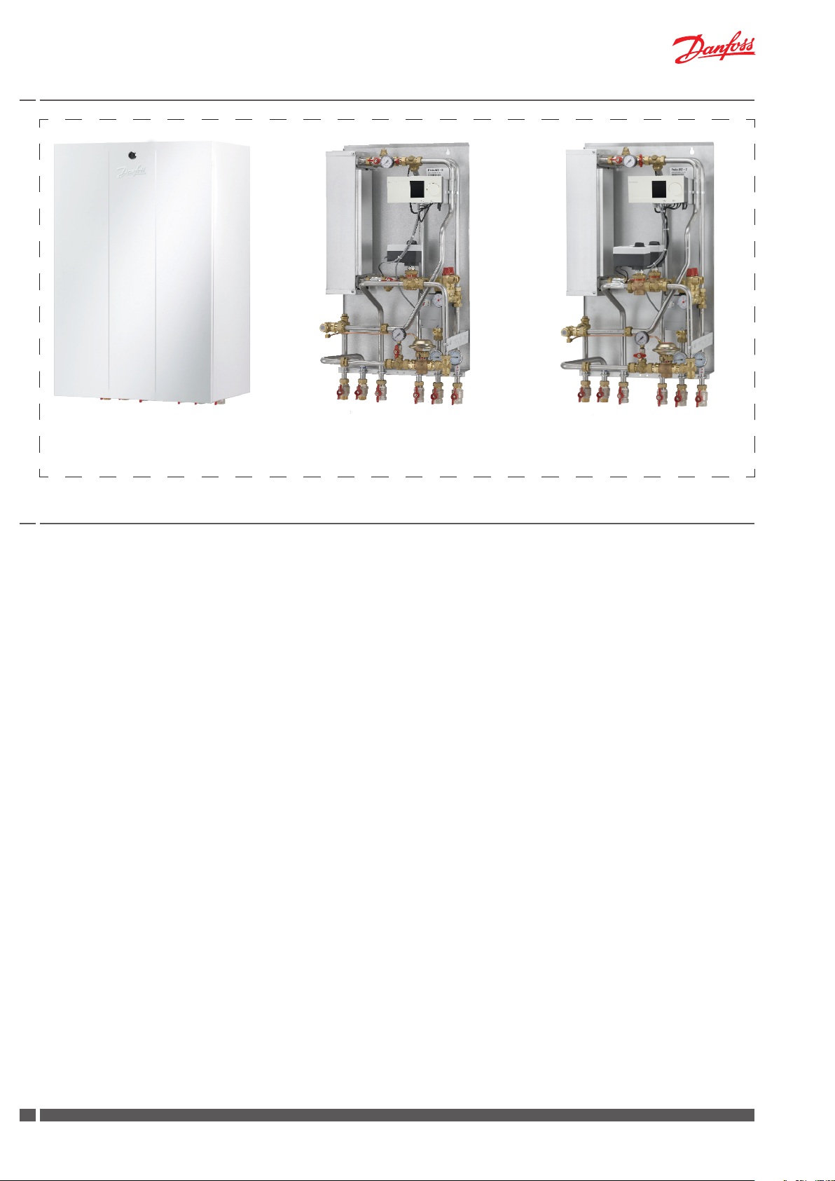
VX Solo 22 with cover VX Solo 22, ECL 310, A230 VX Solo 22, ECL 310, A266
1. Content
1. Content ..................................................................................................................................................................................................................................................2
2. Product introduction, VX Solo 22 - ECL Comfort 310, A230, electronic control of 1 circuit ....................................................................................3
3. Product introduction, VX Solo 22 - ECL Comfort 310, A266, electronic control of 2 circuits ..................................................................................4
4. Enduser instructions, description and initial adjustment ...................................................................................................................................................6
5. Installation instructions, connection, safety and handling .................................................................................................................................................7
6. Installation instructions, GETTING STARTED ............................................................................................................................................................................8
7. Installation instructions, general ..................................................................................................................................................................................................9
8. Electrical connections, ECL Comfort 310 ................................................................................................................................................................................ 10
9. Adjustment and commissioning, lling the system and dierential pressure controller .....................................................................................11
10. Adjustment and commissioning, heating circuit ................................................................................................................................................................ 12
11. Adjustment and commissioning, DHW circuit - only for systems with DHW cylinder control, App. A266 .................................................... 14
12. Operation and maintenance ....................................................................................................................................................................................................... 15
13. Maintenance plan ........................................................................................................................................................................................................................... 16
14. Troubleshooting .............................................................................................................................................................................................................................. 17
15. EU Declaration of Conformity ..................................................................................................................................................................................................... 19
16. Commissioning Certicate .......................................................................................................................................................................................................... 20
2
DKDHR VI.GE.Y1.01 Danfoss District Energy
Page 3
Instructions for installation and use VX Solo 22
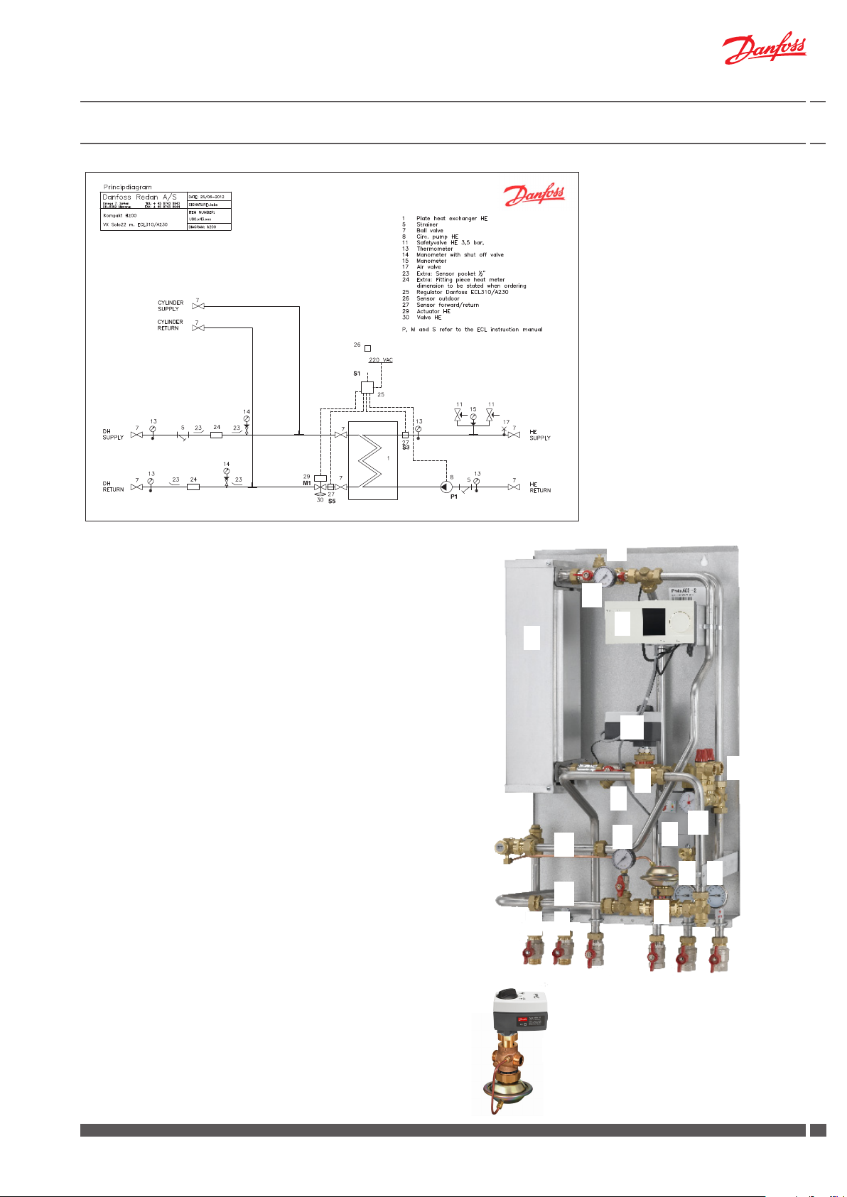
2. Product introduction, VX Solo 22 - ECL Comfort 310, A230, electronic control of 1 circuit
Note!
This diagram is intended as a guide
Principal components
Plate heat exchanger, brazed, HE
1.
Valve housing
2.
2A.
Actuator
3.
Controller Danfoss ECL Comfort 310
4.
Dierential pressure controller AVP-F
5.
Strainer
6.
Thermometer DH supply
7.
Thermometer DH return
8.
Pump, HE
9.
Thermometer, HE supply
10.
Thermometer, HE return
11.
Safety valves, HE
12.
Air valve
13.
Manometer
14.
Fitting piece for heat meter (optional)
15
Can alternatively be replaced by an AVQM controller
Alternative equipment
Fitted standard pump can be replaced with an A-labelled Grundfos
pump. Please contact our sales department for further information.
15
, HE
15
, HE
15
12
13
3
1
2A
11
2
5
13
5
14
13
8
9
10
14
6
7
4
Accessories available as extra equipment
White cover with door - Code No. 144B2056
Replacement parts (heat exchangers without insulation cover)
Heat exchanger XB37M-1 30 Code No. 004B1694
Heat exchanger XB37M-1 40 Code No. 004B1696
Heat exchanger XB37M-1 50 Code No. 004B1697
Danfoss District Energy VI.GE.Y1.02 DKDHR
15
33
Page 4
Instructions for installation and use VX Solo 22
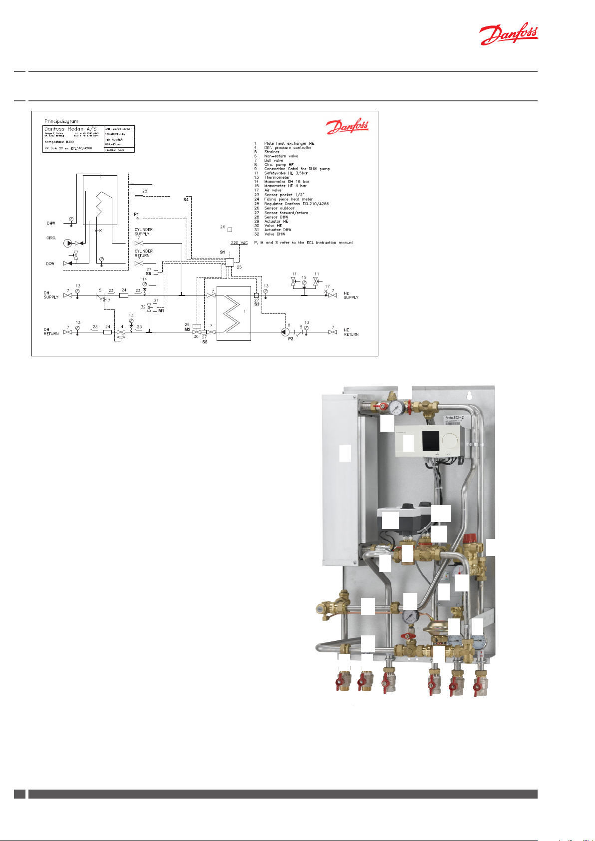
3. Product introduction, VX Solo 22 - ECL Comfort 310, A266, electronic control of 2 circuits
Note!
This diagram is intended as a guide
Principal components
Plate heat exchanger, brazed, HE
1.
Valve housing, HE
2.
2A.
Actuator, HE
3.
Controller Danfoss ECL Comfort 310
4.
Dierential pressure controller AVP-F
5.
Strainer
6.
Thermometer DH supply
7.
Thermometer DH return
8.
Pump, HE
9.
Thermometer, HE supply
10.
Thermometer, HE return
11.
Safety valves, HE
12.
Air valve
13.
Manometer
14.
Fitting piece for heat meter (optional)
15.
Valve housing, connection for DHW cylinder
15A.
Actuator, connection for DHW cylinder
Alternative equipment
Fitted standard pump can be replaced with an A-labelled Grundfos
pump. Please contact our sales department for further information
Accessories available as extra equipment
White cover with door - Code No. 144B2056
12
13
3
1
2A
15A
15
2
11
5
13
8
5
14
13
10
9
14
6
7
4
Replacement parts (heat exchangers without insulation cover)
Heat exchanger XB37M-1 30 Code No. 004B1694
Heat exchanger XB37M-1 40 Code No. 004B1696
Heat exchanger XB37M-1 50 Code No. 004B1697
4
DKDHR VI.GE.Y1.02 Danfoss District Energy
Page 5
Instructions for installation and use VX Solo 22
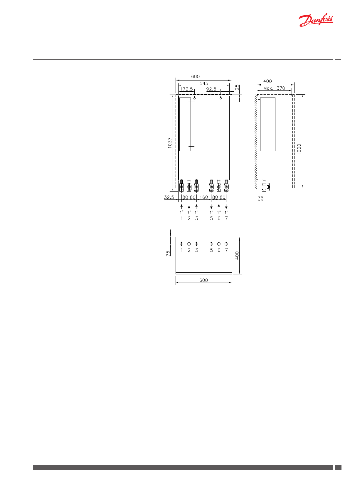
Dimensions:
Dimensions without cover
H1037 x W545 x D370 mm
Dimensions with cover
H1037 x W600 x D400 mm
Connections:
Order:
1 District heating (DH) supply
2 District heating (DH) return
3 Cylinder return
5 Cylinder supply
6 Heating (HE) return
7 Heating (HE) supply
Connections size:
DH, HE: G 1” (IT)
Connection for cylinder: G 1 or ¾” (IT)
Cover
Cover
Cover
Top view
Wall
Danfoss District Energy VI.GE.Y1.02 DKDHR
55
Page 6
Instructions for installation and use VX Solo 22
4. Enduser instructions, description and initial adjustment
Instructions
Please read these instructions carefully before installing and commissioning this unit. The manufacturer accepts no liability for loss
or damage resulting from failure to comply with these instructions
for use. Read and follow these instructions carefully to prevent the
risk of physical injury and/or damage to property. Exceeding the
recommended operating parameters appreciably increases the risk
of personal injury and/or damage to property.
Installation, commissioning and maintenance must be carried out
by qualied and authorised personnel (both plumbing and electrical work).
Once the station has been installed and is operating, there is nor-
mally no need to alter the settings or other functions. The district
heating unit is very reliable and easy to operate.
Warning! Hot surfaces
Parts of the unit may be very hot and can cause burn injuries.
Be very careful when you are in the immediate vicinity of the unit.
Warnings about high pressure and high temperature
The maximum supply temperature in the district heating network can be up to 120°C and the operating pressure can be up
to 16 bar. This may result in a risk of scalding from touching the
unit and from outow of the medium (water/steam). Exceeding
the unit design data and operating parameters for pressure and
temperature carries an appreciable risk of personal injury and/or
damage to property.
Description
These instructions apply to two unit types. One variant with Danfoss
ECL Comfort 310 controller with night-time duty for control of the
heating circuit only (Application A230) as well as a variant with
Danfoss ECL Comfort 310 controller for control of both the heating
circuit (incl. night-time duty) as well as a DHW cylinder circuit (Application A266).
VX Solo 22 units are tted with a dierential pressure controller that
maintains a constant pressure in the radiators. For both VX Solo 22
applications the supply temperature to the heating circuit is controlled electronically.
For VX Solo 22, application A266, the temperature in the DHW cylinder is also controlled electronically.
We recommend regular inspections of the unit - ideally in connection
with readings of the district heating meter.
Pay special attention to any leaks and an excessively high return
temperature in the district heating circuit (poor cooling of the district
heating water). Cooling – i.e. the dierence between the supply and return temperature of the district heating water – has a signicant eect
on the overall energy economy. Please note that the district heating
return temperature is directly related to the return temperature from
the heating circuit (and the return temperature from the domestic
hot water cylinder). Therefore, it is important to focus on the supply
and return temperature in the heating system.
The dierence should typically be 30–35°C in systems that operate
with radiators. In systems that feature oor heating, the dierence is
typically 5–10°C.
Emergencies
In the event of re, leaks or other hazards, immediately shut o
all sources of energy to the unit, if possible, and call for appropriate assistance.
If the domestic hot water is discoloured or malodorous, shut o
all ball valves on the unit notify all users and call for professional
assistance without delay.
Initial setting
VX Solo 22 is electronically controlled (fully automatic) and there
is normally no need to alter the settings or other functions. The
DHW (Application 266) and HE temperatures are set during initial
adjustment and commissioning of the unit.
We suggest that you contact qualied and authorised personnel,
if it becomes necessary to change the parameters (temperatures,
night-time reduction etc.) in the controller.
Irregularities
When reading the meter, check all joints and connections for leaks.
If you identify any irregularities/leaks, contact your professional
provider for assistance.
6
DKDHR VI.GE.Y1.02 Danfoss District Energy
Page 7
Instructions for installation and use VX Solo 22
5. Installation instructions, connection, safety and handling
Instructions
Please read these instructions carefully before installing and commissioning this unit. The manufacturer accepts no liability for loss
or damage resulting from failure to comply with these instructions
for use. Read and follow these instructions carefully to prevent the
risk of physical injury and/or damage to property. Exceeding the
recommended operating parameters appreciably increases the risk
of personal injury and/or damage to property.
Installation, commissioning and maintenance must be carried out
by qualied and authorised personnel (both plumbing and electrical work).
Heat source
The unit is primarily designed for connection to district heating.
Alternative energy sources can be used if the operating conditions
are equivalent to district heating at all times.
Application
The unit is designed exclusively to heat water.
The unit must not be used to heat other media.
The unit is to be connected to the household piping in a frost-free
room, where the temperature does not exceed 50°C, and where the
relative humidity is not higher than 80%. The unit must not be covered, bricked in or otherwise cut o from access.
Choise of materials
Only use materials that comply with local regulations.
Connection
It must be possible to cut o all energy sources to the unit – including
electrical connections – at all times. The unit must be connected to an
electrical equalizer connection.
Potential equalization/grounding
Potential equalization is an electrical equalizer connection to secure
against user contact with dangerous voltage, which may occur for
example between two piping systems. Potential equalization reduces
corrosion in heat exchangers, water heaters, district heating units and
plumbing installations. Equalization of potentials should be eected
according to local regulations.
Warning! Hot surfaces
Parts of the unit may be very hot and can cause burn injuries. Be very
careful when you are in the immediate vicinity of the unit.
Warnings about high pressure and high temperature
The maximum supply temperature in the district heating network
can be up to 120°C and the operating pressure can be up to 16 bar.
This may result in a risk of scalding from touching the unit and from
outow of the medium. Exceeding the unit design data and operating
parameters for pressure and temperature carries an appreciable risk of
personal injury and/or damage to property.
Corrosion
The maximum chlorine content of the medium must not be higher
than 300 mg/l. The risk of corrosion increases considerably if the
recommended chlorine content is exceeded.
Safety valve(s)
Safety valves must always be installed in accordance with the applicable local regulations.
Noise level
≤ 55 dB
Storage
Before installation, the unit(s) must be stored in a dry, heated (i.e. frostfree) room.
(Relative humidity max. 80% and storage temp. 5–70°C).
The units must not be stacked higher than the limit at the factory. Units
supplied in cardboard packaging must be lifted using the handles
incorporated in the packaging. Units must be placed on pallets for
transport/moving across large distances.
As far as possible, do not lift the unit by the pipes. Lifting by the pipes
may cause leaks. REMEMBER to retighten.
Emergencies
In the event of re, leaks or other hazards, immediately shut o all energy
sources to the
If the
valves on the unit, notify all users and call professional assistance without delay.
Warning about damage during transport
On reception of the unit, and before installing it, check for any evidence
of damage during transport.
The unit must be handled and moved with the greatest care and attention.
NB! - Tightening of connections
Before lling the unit with water, ALL pipe connections MUST be
retightened, as vibrations during transport may have caused leaks.
Once the unit has been lled and the system is hot, ALL pipe connections MUST be retightened once more. DO NOT OVERTIGHTEN THE
PIPE CONNECTIONS – see page 9, “Test & connections”.
Handling
We recommend that you wear suitable safety footwear while handling
and installing the unit.
We recommend that you wear suitable safety working gloves while
handling and installing the unit.
Do not remove any transport brackets until the unit is in the immediate
vicinity of the installation site.
unit
, if possible, and call appropriate assistance.
domestic hot water
is discoloured or malodorous, shut o all ball
Disposal
Dispose of the packaging in accordance with the local regulations for
disposal of used packaging materials. The unit is made of materials that
cannot be disposed of together with household waste.
Close all energy sources and disconnect all connection pipes. Disconnect
and dismantle the product for disposal in accordance with the applicable
local regulations for the disposal of the individual components.
Danfoss District Energy VI.GE.Y1.02 DKDHR
77
Page 8
Instructions for installation and use VX Solo 22
6. Installation instructions, GETTING STARTED
Connect the unit to the household piping in accordance with the
labelling at the bottom and/or in accordance with the instructions
in this manual.
Please also refer to page 9, top, Installation instructions, General.
Mount VX Solo 22 on a solid wall using expansion bolts or similar.
Please note that the unit weighs more than 60 kg!
See page 9 for more details.
GETTING STARTED is a quick guide and some details in connection
with installation and commissioning may require additional information, which can be found elsewhere in this instruction manual.
1. When the unit has been securely mounted, close all shut-o
valves on supply and return pipes before connecting the unit
to the household piping
2. Mount the district heating meter (if the unit includes built-in
tting piece for heat meter - see page 9 in the instructions, if
necessary)
3. IMPORTANT! Tighten all pipe connections, as they may
have loosened during transport and handling (do NOT
overtighten!) - check that the air valve in top of the unit is
closed
4. Install properly sized expansion vessel on the heating system
5. Establish a drain connection on the safety valves in compliance with the aplicable legislation
6. Open the ball valves for HE supply and return and ll the
system with water. Filling of water to the heating system must
be done through connection to an exterior cold water supply.
(see instructions on page 11)
7. Fill the DHW cylinder with water
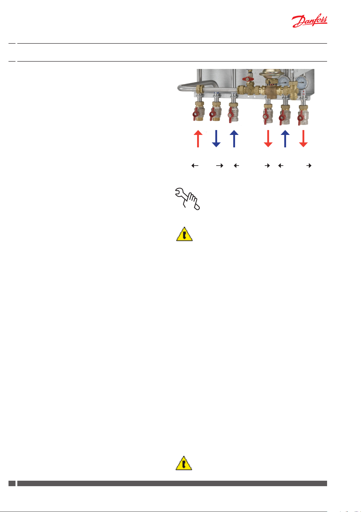
District heating
supply return
Primary
Connection for cylinder
return supply
Primary
HE
return
Secondary
HE
supply
8. Then carefully open the ball valve for the district heating
supply ow, and nally open the ball valve for the district
heating return ow as well as the connection pipe for the
DHW cylinder
9. Check the unit and the household piping thoroughly for leaks
10. Pressure test the entire system for leaks in accordance with
the applicable regulations
11. Connect the ECL automatics to the electricity supply, but do
not switch on the power
12. Heat the system and vent the radiator circuit/heating side
thoroughly on the radiators and the air valve, see pages 11
and 15 “Venting of system” in the instruction manual
13. Now switch on the automatics at the mains
14. Finish by adjusting the unit in accordance with the instructions and remember to ll-in the commissioning certicate
on page 20
15. IMPORTANT! Heating and cooling of the system may cause
leaks. Therefore it may be necessary to retighten the connections in the period after commissioning.
8
DKDHR VI.GE.Y1.02 Danfoss District Energy
Page 9

Instructions for installation and use VX Solo 22
7. Installation instructions, general
The installation, connection and maintenance of the unit must be
performed by qualied and authorised personnel. Installation must
always be performed in accordance with the applicable legislation
and in compliance with these instructions.
The unit must be installed so that it is freely accessible and can
be maintained without unnecessary disruption. Lift the unit by its
mounting plate/rear section (as far as possible do not lift the unit
by the pipes) and secure it to a solid wall using 2 expansion bolts or
the like positioned in the two keyholes in the mounting plate/rear
section. It is recommended that at least two people are involved in
the installation.
We recommend positioning of rubber spacers between the wall
and the unit to prevent the transfer of resonance noise from the
pump into the wall.
Before commissioning, rinse all the pipes in the household piping system thoroughly to remove any impurities, and check and clean the dirt
strainers in the unit.
Test and connections
Before lling the system with water, retighten all the pipe connections because vibrations and shocks during transport and handling
may have caused leaks. Once the system has been lled with water,
tighten all the pipe connections once more before performing pressure test for leaks. After heating of the system, check all the connections and retighten if necessary.
Please note that the connections may feature EPDM rubber gaskets!
Therefore, it is important that you DO NOT OVERTIGHTEN the
union nuts. Overtightening may result in leaks. Leaks caused by
overtightening or failure to retighten connections are not covered
by the warranty.
Fitting piece for heat meter
As standard the VX Solo 22 is supplied without built-in tting piece
for heat meter.
If the unit is ordered with built-in tting piece for heat meter this is
mounted as described below.
Fitting of heat meter
- Close the ball valves on the district heating line
- Loosen the union nuts at both ends of the tting piece (14) and
remove it
- Fit/fasten the heat meter - remember gaskets
- Mount temperature sensors in sensor pockets (according to
meter regulations)
- Remember to check and tighten all pipe connections before
commissioning the heat meter.
Safety valve
Always lead the blow-o pipes from the safety valves (11) to a
drain in accordance with applicable legislation.
Expansion vessel
A suitable expansion vessel is to be connected to the heating system on site. It is the developer’s/contractor’s responsibility to install
a properly sized and approved expansion tank with the required
initial pressure.
14
14
11
Danfoss District Energy VI.GE.Y1.02 DKDHR
99
Page 10

Instructions for installation and use VX Solo 22
8. Electrical connections, ECL Comfort 310
Electrical connection
The electrical connection of the unit must be performed by authorised
personnel. The unit is to be connected to a 230 V AC mains power supply.
The power supply/connection must be carried out in accordance with
the applicable regulations and instructions.
The unit must be connected to an external switch so that it can be disconnected in connection with maintenance, cleaning and repairs or in
the event of an emergency.
As standard the VX Solo 22 is supplied with Danfoss ECL Comfort 310
with Application A230 or Application 266. The control equipment includes actuator(s) and sensors installed in the unit and the controller,
placed/mounted on the mounting plate in top of the unit.The controller
is electrically wired to sensors, pump and actuator(s).
Connection of outdoor sensor and immersion sensor, if any, as well as
connection to circulation pump on the DHW circuit (not part of the
delivery) is carried out in accordance with below instructions.
Installation of outdoor sensor (ESMT)
The outdoor temperature sensor is supplied loose with the unit.
It is to be mounted on site as shown in the drawings to the right.
Always mount the sensor on the coldest side of the building (normally
the north side).
It must not be exposed to morning sunlight, and must not be positioned above windows, doors, ventilation ducts, balconies under
overhanging roof sections, or close to any other heat source.
Installation height: approx. 2.5 m above ground level.
Temperature range: -50 to 50° C.
Electrical connection
The cables can be connected to the sensor in any order.
Connection cable: 2 x 0.4 - 1.5 mm²
The cable ends are connected to the ECL 310 controller in common
ground terminal and in terminal 29. See below
VX Solo 22 med electronic control of both circuits (App. A266)
The controller is prepared for connection of immersion sensor S4 (DHW
cylinder is not part of the delivery) and connection of an external circulation pump. The return ow sensor S6 (ESMC) from the cylinder is
mounted in the unit and is electrically wired to the controller.
Controller ECL Comfort 310
Supply voltage: 230 V AC - 50 Hz
Power consumption: 5 VA
Actuator AMV 10 / AMV 150
Supply voltage: 230 V AC - 50 Hz
Power consumption: 2 VA / 8 VA
Pumps Wilo Yonos PARA or Stratos PARA
(Alternatively: Grundfos Alpha 2 or Magna)
Supply voltage: 230 V AC - 50/60 Hz
Power consumption:
Wilo Max 45 Watt (Yonos) / 70 Watt (Stratos)
Grundfos Max 25 Watt (Alpha2) / 185 Watt (Magna)
230 V a.c. , A266.1 / A266.2 / A266.9
Mounting of immersion sensor (ESMU)
Sensor pocket and sensor are supplied loose and must be mounted
and connected to the controller on site in accordance with the cylinder
supplier’s instructions. A cable for the immersion temperature sensor
is preinstalled in the controller and is marked S4 (immersion sensor).
If it is necessary to change the cable, the new cable must be mounted
in common ground terminal and in terminal 26. Se below.
The minimum area for the cable is 0,4 mm² and max. length is 125 m.
Mounting of external circulation pump (domestic hot water)
The externally placed circulation pump is prepared for connection
to preinstalled cable marked P1.
If it is necessary to change the cable, the new cable must be mounted
in common ground terminal N and terminal 11 or 12. See below.
Access to ECL base part
Access to the base part for connection of outdoor sensor or the like
is obtained by pulling the lock (pin) down with a screwdriver until a
yellow line is visible on the lock. Then, the front piece can easily be
removed. Locking is achieved by pressing the lock up.
Common ground
terminal
Lock / pin
10
DKDHR VI.GE.Y1.02 Danfoss District Energy
ECL Comfort 310 base part
Page 11

Instructions for installation and use VX Solo 22
9. Adjustment and commissioning, lling the system and dierential pressure controller
General information
PLEASE NOTE! Some models may have a slightly dierent appearance,
but the control function is in principle the same as described below.
Commissioning
Commission the unit in accordance with the instructions on page
8 -10.
Filling the system
Filling of water to the heating system must be done through connection to an exterior cold water supply.
Check and tighten all connections before adding water to the system,
as vibrations during transport may have caused leaks. After having
added water to the system, tighten all the connections before performing leak test.
Then heat up the system, check the connections and tighten once
again if necessary.
Before adding water to the system and rst start-up, check if:
- pipes are connected according to the circuit diagram,
- expansion vessel is connected,
- heat meter is mounted,
- shut-o valves are closed,
- threaded and anged connections are tightened.
Filling the system - (Note, by means of exterior cold water supply):
1. Pump must be switched o when water is added to the system.
2. Fill heat exchanger and system with water until the manometer
shows a working pressure, which corresponds to the system
height + 5 m (approx. 1.5 - 2.0 bar)
3. Vent the system completely.
4. Start the pump.
Dierential pressure controller (common return pipe
- only Application A266)
The dierential pressure controller, Danfoss AVP-F reduces the high
uctuations in pressure in the district heating network, ensuring a
small and constant operating pressure across the unit. This ensures
optimum operating conditions for the control equipment.
The dierential pressure controller closes on rising dierential
pressure.
The dierential pressure controller is preset to a xed value from
factory and should not be adjusted afterwards.
Please refer to enclosed producer instructions for further
information.
Instructions AVP-F
Danfoss District Energy VI.GE.Y1.02 DKDHR
1111
Page 12

065R9074
Instructions
082R9086
Instructions for installation and use VX Solo 22
10. Adjustment and commissioning, heating circuit
Danfoss ECL Comfort 310
The temperature for the heating circuit is controlled electronically by
a Danfoss ECL 310 controller. The ECL controller is supplied with an
ECL Application Key A230 or A266. The application Key contains information about application, language and factory settings, adapted
to the type of system, for which it is ordered.
Note! Various applications can be loaded.
The controller is factory-set for local language and the running time
for the actuator (heating circuit) is preset for the actual application.
General controller settings such as “ Time and Date” must be entered
during commissioning of the controller. And also the desired supply
ow temperature must be set.
Please refer to the enclosed manufacturer instructions for the ECL
210/310 controller in order to set the required temperature for
the heating circuit:
ECL Application Key Box with ECL Comfort 210/310 user guide and
mounting guide, for further information.
We recommend that your order commissioning of the controller with
your local Danfoss representative.
Note, in systems that feature only oor heating it is important that the
supply temperature does not exceed 35°C, and ALWAYS check the
instructions from the oor supplier ( typically for wooden oors).
Manual override
Instructions
AVQM, AVQMT – PN 16, 25 / DN 15-50
AVQM (PN 16) AVQM (PN 25) AVQMT (PN 25) AVQMT/AVT (PN 25)
082R9086
AMV 10
Actuator + valve, unit with electronic control of heating circuit only
Application A230
The VX Solo 22, A230 is supplied with a Danfoss AVQM tted to the
primary return pipe. The AVQM controller is used together with an
electrical actuator Danfoss AMV 10. The AVQM is a self-acting ow controller with integrated control valve primarily for use in district heating
systems. The controller is normally open and closes when set max. ow
is exceeded.
Flow setting
Flow setting is being done by the adjustment of the ow restrictor position. The adjustment can be performed on the basis of ow adjustment diagram (see relevant instructions) and / or by the means of heat
meter.
See also enclosed manufacturer instructions:
Instructions AVQM
Factory-setting
The AVQM controller and the actuator have undergone a functional
test from factory.
The ow limiter is not set/adjusted from factory.
In the event of operating disturbances the AMV actuator can be shut
o manually in accordance with enclosed instructions, by turning
the manual override knob on top of the actuator clockwise. Please
note that the knob can be “tight” to turn.
See also enclosed manufacturer instructions:
Instructions AMV 10
Actuator + valve, unit with control of heating- and DHW cylinder
circuits, Application A266
For controlling the heating circuit the VX Solo 22, A266 is supplied
with a Danfoss AMV 10 actuator with Danfoss valve type VM2,
placed on the primary return ow pipe. The AMV actuator is electrically wired to the controller from factory.
Factory setting
The actuator has undergone a functional test and is preset from
factory.
In the event of operating disturbances the actuator can be shut o
manually in accordance with enclosed instructions, by turning the
manual override knob on top of the actuator clockwise. Please note
that the knob can be “tight” to turn.
DN 15-32 DN 15-5 0 D N 32-50 D N 15- 50 DN 32-50 DN 15-50 DN 32-50
∆p = 0.2 ∆p = 0.2 ∆p = 0.2 ∆p = 0.2 ∆p = 0.2 ∆p = 0.2 ∆p = 0.2
Flow (and temperature) controller with integrated control
ENGLISH
valve AVQM, AVQMT
Flow- (og temperatur-)regulator med indbygget motorventil
DANSK
AVQM, AVQMT
Volumenstrom (und Temperatur-) Regler mit Motorstellventil
DEUTSCH
AVQM, AVQMT
Regulador de caudal (y temperatura) con válvula de control
ESPAÑOL
integrada AVQM, AVQMT
Regulator pretoka (in temperature) z regulacijskim ventilom
SLOVENŠČINA
AVQM, AVQMT
Regulator przepływu (i temperatury) z zaworem
POLSKI
regulacyjnym AVQM, AVQMT
Térfogatáram(és hőmérséklet) szabályozó, motoros
MAGYAR
szabályozó-szeleppel egybeépítve AVQM, AVQMT
Uputstvo AVQM, AVQMT-PN 16, 25/DN 15-50 grejanje.danfoss.com Strana 21
SRPSKI
73695050 DH-SMT/SI VI.DB.T2.1N © Danfoss 09/2009 1
065R9074
VM2 VB2
7369053-0SIBC VI.HB.C1.00 © Danfoss 5/02 1
Instructions
VM2, VB2 2-way
DN L (mm)
15 65
20 70
25 75
32 100
40 110
50 130
DN L1(mm)
15 131
20 142
25 159
32 196
40 196
50 228
DN L2(mm)
15 139
20 154
25 159
32 184
40 294
50 330
DN L3(mm)
15 69
20 74
25 79
32 104
40 114
50 134
www.danfoss.com Page 7
www.danfoss.dk Side 9
www.danfoss.de Seite 11
www.danfoss.es Página 13
www.danfoss.si Stran 15
www.danfoss.pl Strona 17
www.danfoss.hu Oldal 19
AMV 10 + VM2, VS2 AMV 10 + VB2 AMV 10 + VMV AMV 10 + AVQM
3
7369215-6 EI.96.E2.00 © Danfoss 02/02 1
2
1
N - 1
N - 3
Alternative actuator
AMV150 and valve
housing VS2
Instructions
AMV 150
AMV 150 + AMV 150 + AMV 150 +
VS2 (DN 15) VMV AVQM (DN 15)
Actuators for three point control AMV 150 www.danfoss.com Page 2
ENGLISH
Motorer til 3-punkts styring AMV 150 www.danfoss.dk Side 3
DANSK
Stellantriebe für 3-Pkt.- Eingangssignal AMV 150 www.danfoss.de Seite 3
DEUTSCH
Motor för 3-punktsreglering AMV 150 varme.danfoss.se Sida 4
SVENSKA
Servomotor met 3-puntssturing AMV 150 www.danfoss.nl Pagina 4
NEDERLANDS
Pavaros trijų padėčių valdymui AMV 150 www.danfoss.lt 5 puslapis
LIETUVIŲ K.
Motori trīs punktu kontrolei AMV 150 www.danfoss.com Lpp. 5
LATVISKI
Szelepmozgatók hárompontos szabályozáshoz AMV 150 www.danfoss.com 6. oldal
MAGYAR
Servopohony s tříbodovým regulačním signálem AMV 150 www.danfoss.cz Strana 6
ČESKY
Siłowniki sterowane sygnałem 3-punktowym AMV 150 ww w.danfoss.pl Strona 7
POLSKI
РУССКИЙ
Электроприводы для трехпозиционного регулирования AMV 150
www.danfoss.ru Страница 7
12
DKDHR VI.GE.Y1.02 Danfoss District Energy
Page 13

Instructions for installation and use VX Solo 22
Pump - Wilo Stratos PARA / Yonos PARA (system with ECL)
The pump is factory connected to the ECL controller.
On systems with ECL controller turn the red switch to the right (constant curve) and set it to “Max. pos.” initially. Then set the pump to the
lowest possible position, depending on the heating requirement for
the building - taking into account aspects such as cooling and power
consumption.
Venting: The pump features a built-in venting function, which can
be used when the system needs to be bled. Turn the red switch to
the vertical position. The pump will then run a venting routine that
lasts 10 minutes. There may be some noise during this phase. Once
the 10-minute period is nished, reset the pump according to the
instructions above.
For additional information, see the manual: Wilo Stratos PARA /
Yonos PARA.
Summer operation (all pump types)
Outside the heating period, the pump will be disconnected automatically from the heating system. During the summer period, the controller will start the pump for a minute at least once every three days to
prevent the pump from blocking.
Monterings- og driftsvejledning
Wilo-Stratos højeffektivitetspumpe
2 030 388 / 0210
Med forbehold for tekniske ændringer!
or
Start-up after summer operation - venting
Please note that it may be necessary to vent the system again. To vent
the system, use the vent valve in the substation or on the radiators
and, if appropriate, the air valve at the highest point of the system.
Alternative pump - Grundfos Magna / Alpha2 (system with ECL)
The pump ist factory-set to control mode AutoADAPT without automatic nicht-time duty. The automatic night-time duty function is
not to be used.
On systems with ECL select control mode: constant-pressure control (see chapter on “Setting of control mode”) and then the setpoint is adjusted to the actual system characteristics.
Please see enclosed instructions:
GRUNDFOS MAGNA, GRUNDFOS INSTRUCTIONS
or GRUNDFOS ALPHA2
Constant pressure
Max. pos.
Constant pressure
Max. pos.
Venting
Vertical pos.
Venting
Vertical pos.
Variable pressure
Max. pos.
Variable pressure
Max. pos.
GRUNDFOSINSTRUCTIONS
GRUNDFOS MAGNA
Series 2000
MAGNA 25-40, 25-60, 25-100, 32-40, 32-60, 32-100, 40-100(D), 50-100
Installation and operating instructions
or
Please note, that the system cannot be vented through the pump.
Danfoss District Energy VI.GE.Y1.02 DKDHR
1313
Page 14

065R9074
Instructions for installation and use VX Solo 22
11. Adjustment and commissioning, DHW circuit - only for systems with DHW cylinder control, App. A266
Danfoss ECL Comfort 310 - Application A266
The application Key contains information about application, language and factory settings, adapted to the type of system, for which
it is ordered.
Note! Various applications can be loaded.
The controller is factory-set for local language and the running time
for the actuator (DHW circuit) is preset for the actual application.
General controller settings such as “ Time and Date” must be entered
during commissioning of the controller. And also the desired DHW
temperature must be set.
(Make sure that the immersion sensor is placed correctly before making adjustment of the temperature).
Please refer to the enclosed manufacturer instructions for the ECL
210/310 controller in order to set the required domestic hot water
temperature in the DHW cylinder circuit:
We recommend that that your order commissioning of the controller
with your local Danfoss Sales Company.
Actuator + valve, unit with control of the heating and DHW cylinder circuits, Application A266
For controlling the domestic hot water circuit the VX Solo 22, A266
is supplied with Danfoss AMV 10 actuator with Danfoss valve housing type VM2 placed on the primary return ow pipe. The AMV actuator is electrically wired to the controller from the plant. (Alternatively the unit can be supplied with AMV150 actuator and valve
VS2).
The actuator has undergone a functional test and is preset from
factory.
In the event of operating disturbances the actuator can be shut o
manually in accordance with enclosed instructions, by turning the
manual override knob on top of the actuator clockwise. Please note
that the knob can be “tight” to turn.
Instructions
AVQM, AVQMT – PN 16, 25 / DN 15-50
AVQM (PN 16) AVQM (PN 25) AVQMT (PN 25) AVQMT/AVT (PN 25)
DN 15-32 DN 15-50 DN 32-50 DN 15-50 DN 32-50 DN 15-50 DN 32 -50
∆p = 0.2 ∆p = 0.2 ∆p = 0.2 ∆p = 0. 2 ∆p = 0.2 ∆p = 0.2 ∆p = 0. 2
Flow (and temperature) controller with integrated control
ENGLISH
valve AVQM, AVQMT
Flow- (og temperatur-)regulator med indbygget motorventil
DANSK
AVQM, AVQMT
Volumenstrom (und Temperatur-) Regler mit Motorstellventil
DEUTSCH
AVQM, AVQMT
Regulador de caudal (y temperatura) con válvula de control
ESPAÑOL
integrada AVQM, AVQMT
Regulator pretoka (in temperature) z regulacijskim ventilom
SLOVENŠČINA
AVQM, AVQMT
Regulator przepływu (i temperatury) z zaworem
POLSKI
regulacyjnym AVQM, AVQMT
Térfogatáram(és hőmérséklet) szabályozó, motoros
MAGYAR
szabályozó-szeleppel egybeépítve AVQM, AVQMT
Uputstvo AVQM, AVQMT-PN 16, 25/DN 15-50 grejanje.danfoss.com Strana 21
SRPSKI
73695050 DH-SMT/SI VI.DB.T2.1N © Danfoss 09/2009 1
Alternative actuator
AMV150 and valve
housing VS2
065R9074
www.danfoss.com Page 7
www.danfoss.dk Side 9
www.danfoss.de Seit e 11
www.danfoss.es Página 13
www.danfoss.si S tra n 15
www.danfoss.pl Strona 17
www.danfoss.hu Oldal 19
7369053-0SIBC VI.HB.C1.00 © Danfoss 5/02 1
VM2 VB2
Instructions
VM2, VB2 2-way
DN L (mm)
15 65
20 70
25 75
32 100
40 110
50 130
DN L1(mm)
15 131
20 142
25 159
32 196
40 196
50 228
DN L2(mm)
15 139
20 154
25 159
32 184
40 294
50 330
DN L3(mm)
15 69
20 74
25 79
32 104
40 114
50 134
14
DKDHR VI.GE.Y1.02 Danfoss District Energy
Page 15

Instructions for installation and use VX Solo 22
12. Operation and maintenance
Meter reading
The caretaker/owner must perform visual checking and reading of the
district heating meter at short, regular intervals in accordance with
the maintenance plan, page 16. (Please notat that the meter is not a
part of the delivery from Danfoss).
Service procedures must only be performed by trained, authorised
personnel.
NB! Excessive consumption for whatever reason is not covered by
the Danfoss warranty.
Inspection
The unit should be checked regularly by authorised personnel. Any
necessary maintenance must be performed in accordance with the
instructions in this manual and other sets of instructions.
During service the dirt strainers are to be cleaned – including the
lter on the controller, all pipe connections must be tightened and
the safety valve (pos. 11) must be function tested by turning the lever.
Always lead the blow-o pipes from the safety valves to a drain in
accordance with applicable legislation.
Rinsing/cleaning of pla te heat exchanger
To clean the plate heat exchanger, rinse it by running clean water
through the exchanger at high speed and in the opposite direction to
the normal flow. This will remove any dirt deposits that may have built
up in the exchanger. If rinsing with clean water is not sufficient, the exchanger can also be cleaned by circulating a cleaning agent approved
by Danfoss (e.g. Radiner Fl cleaning fluid) through the exchanger. Use
an environmentally friendly cleaning fluid, which can be disposed off
through the standard sewer system. After use of a cleaning fluid, the
plate heat exchanger must be rinsed thoroughly with clean water.
11
Venting
During start-up (of the heating season) always vent the radiator circuit/heating side, the pump and the unit. To vent the unit, use the
air valve (pos. 12)) in the unit. Vent the radiator circuit/heating side
on the bleed screws of the radiators. Vent the pump according to
instructions in the pump manual.
Measures after maintenance work
After maintenance work and before commissioning:
– Check that all screwed connections are tight.
– Check that all safety features, covers, that were removed, have been
replaced properly.
– Clean the working area and remove any spilled materials.
– Clear all tools, materials and other equipment from the working area.
– Connect to energy supply and check for leaks.
– Vent the system.
– Carry out any necessary adjustment again.
– Make sure that all safety features on the device and the system work
properly.
Cooling / Return temperature reading
Cooling – i.e. the dierence between the supply and return temperature of the district heating water – has a signicant eect on overall
energy economy. Please note that the district heating return temperature is directly related to the return temperature from the heating circuit (and the return temperature from the domestic hot water
cylinder). Therefore, it is important to focus on the supply and return
temperature in the heating system. The dierence should typically be
30–35°C in systems that operate with radiators. In systems that feature
oor heating, the dierence is typically 5–10°C. In these systems the
supply temperature should not exceed 35°C.
Luftskrue
12
Tightening of connections
When reading the meter check that all connections are tight. If leaks
are found, contact authorized personnel immediately.
Danfoss District Energy VI.GE.Y1.02 DKDHR
1515
Page 16

Instructions for installation and use VX Solo 22
13. Maintenance plan
Maintenance plan (recommendations)
Interval Maintenance work
Comments
At least once per month
At least once a year
Read meter and check the system for leaks
Check all connections for leaks
Check that the safety valves are functioning correctly. Check the functionality by turning the lever on the safety valves
Check that all components are intact and functioning as
intended
Clean all dirt lters/strainers in the unit Replace any lters that are not intact
Check that any electrical cables are in serviceable condition
and that it is possible to disconnect the electrical power
supply to the unit
Check the pipes and exchanger for signs of corrosion Visual check
Check that insulation cover, if any, is functioning as intended Check that the insulation ts tightly around the product/unit
Check that the temperature regulators are set in accordance
with the instructions in this manual
Check the functions of all shut-o valves Check that the ball valves open and close as they should
*)Enduser/caretaker.
Note! After maintenance work has been carried out all gaskets
HAVE to be replaced.
Note the read meter values in a control book - contact authorized personnel immediately in case of leaks or other irregu lariti es
If you identify a leak, replace the gaskets and retighten the pipe connections
In the event of irregularities, lack of functionality or visible faults and
defects in a component, replace the component in questionn
Visual check. Check whether it is possible to disconnect the current to
the unit.
Follow the instructions in the present manual
16
DKDHR VI.GE.Y1.02 Danfoss District Energy
Page 17

Instructions for installation and use VX Solo 22
14. Troubleshooting
Fundamental
In the event of disruptions to operation , you should fundamentally - before commencing the actual troubleshooting - check
whether:
• the system is correctly connected
• the district heating supply temperature is at its normal level
• the dierential pressure is at its normal level - ask your district
heating supplier if necessary
Problem Possible cause Solution
Dirt strainer in the district heating or
heating return line clogged.
Filter in district heating meter clogged.
No heat
Defective or wrongly adjusted dierential pressure controller.
Air pockets in the system.
Uneven distribution of heat Air pockets in the system.
Insucient heating surface / radiators
too small compared to the total heating
Poor cooling
requirement of the building.
Poor utilisation of the existing heating
surface.
• there is a power supply to the system - pump and automatics
• the dirt strainer in the district heating supply pipe is clean
• there is air in the system (if the system is vented)
Clean the lter / dirt strainer.
Clean the lter (in consultation with the
district heating plant).
Check the functions of the dierential
pressure controller - if necessary, clean the
valve seat.
Vent the installation thoroughly - see the
instructions.
Vent the installation thoroughly - see the
instructions.
Increase total heating surface.
Turn on all radiators and prevent the radiators in the system from becoming warm
at the bottom.
Defective actuator - or possibly dirt in
the valve housing.
Automatic components/controller
incorrectly adjusted or defective - or
possibly power outage.
No heat
Danfoss District Energy VI.GE.Y1.02 DKDHR
The pump is not working.
The pump is set at too low speed of rotation (not all system types).
Air pockets in the system.
Check that the actor is functioning correctly - clean the valve seat if necessary.
Check that the controller setting is correct - see the separate instructions for the
controller.
Check the power supply.
Temporarily set the actuator to “manual”
control - see the instructions for the heating system.
Check that there is a power supply for the
pump, and that it is operating.
Check that there is no air in the pump
housing - see pump manual.
Set the pump to a higher speed - see the
instructions for the heating system.
Vent the installation thoroughly - see the
instructions.
1717
Page 18

Instructions for installation and use VX Solo 22
Problem Possible cause Solution
Calied heating element in DHW cylinder.
DHW*, no hot water
Inadequate cylinder capacity.
Non-return valve in thermostatic mixer
in the bathroom defective - results in hot
Temperature too low / variations in
temperature
Lack of hot water pressure Strainer in the cold water meter clogged.
Long wait for hot water Circulation pump out of order.
No hot water / temperature too low
and cold water mixing. Please note that
uctuating temperatures may occur at
other tapping points in the system!
NB, Check all mixers in the house for
faults/defects!
Dirt strainer in the district heating supply line clogged.
Clean DHW cylinder with acid solution or
replace heating element.
Wait for heating / loading of the cylinder.
You may check the specications of the
manufacturer conc. cylinder capacity.
Replace the mixer or perhaps only the
non-return valve.
Clean the strainer (cold water meter,
in consultation with the water supply
company).
Check whether the pump is running and whether there is a power supply to
the pump. Make sure that there is no air
in the pump housing.
Clean the dirt strainer.
Controller incorrectly adjusted or defec-
Hot water temperature too high
Temperature falls during tapping
(lack of capacity)
Poor cooling Calied heating element.
Discoloured water (during a protracted
period)
*Please note that (generally) the cylinder and the circulation pump are not part of the Danfoss Redans delivery.
tive.
Defective immersion sensor.
The immersion thermostat sensor incorrectly tted in the cylinder.
Heating element short-circuited. Replace the cylinder.
Check that the setting of the controller
is correct.
Replace sensor.
Place sensor correctly, see page 10. You
may contact Danfoss Redan A/S for
further information.
Clean DHW cylinder with acid solution or
replace heating element in accordance
with manufacturer instructions for the
cylinder.
18
DKDHR VI.GE.Y1.02 Danfoss District Energy
Page 19

Instructions for installation and use VX Solo 22
15. EU Declaration of Conformity
EC-DECLARATION OF CONFORMITY
For CE marking in EU (European Union)
Danfoss Redan A/S, District Energy
DK-8382 Hinnerup
Declares under our sole responsibility that below products including all available power and control options:
VX Solo 22
VX 22 - S 22
Main components: See instruction.
Covered by this declaration is in conformity with the following directive(s), standard(s) or other normative document(s), provided that the products are used in accordance with our instructions.
EU Directives:
EMC Directive 2004/108/EEC
EN 61000-6-1 2007 Electromagnetic compatibility- Generic standard: Immunity for residential, commercial and light
industry.
EN 61000-6-2 2005 Electromagnetic compatibility- Generic standard: Immunity industry.
EN 61000-6-3 2007 Electromagnetic compatibility- Generic standard: Emission for residential, commercial and light
industry.
EN 61000-6-4 2007 Electromagnetic compatibility- Generic standard: Emission industry.
Machinery Directive 2006/42/EEC
EN ISO 14121-1 Safety of machinery -- Risk assessment
EN 60204-1-Safety of machinery - Electrical equipment of machines — Part 1: General requirements
PED Directive 97/23/EEC
Conformity assessment procedure followed: Module A - Internal control of production
All substations that falls under Article 3 §3 and category 1 shall not be CE-marked according to this directive
CE marked affixed year 2010
Approved by:
Place and date of issue: Hinnerup, April 24th, 2012
Name: Thavarupan Perinpam
Title: Quality and Lean Manager
Danfoss Redan A/S
District Energy
Omega 7, Søften
DK-8382 Hinnerup
Telephone +45 87 43 89 43
Danfoss District Energy VI.GE.Y1.02 DKDHR
1919
Page 20

Instructions for installation and use VX Solo 22
16. Commissioning Certicate
Commissioning certicate
The unit is the direct link between the district heating supply network and the household piping system. All supply pipes and the pipes in
the household piping system must be checked and rinsed before commissioning. Once the system has been lled with water, all pipe connections must be retightened before performing pressure test for leaks. The dirt strainers must be cleaned and the unit must be adjusted
in accordance with the instructions in this manual.
It is important to comply with all technical regulations and the applicable legislation in every respect.
Installation and commissioning must only be performed by trained, authorised personnel.
The unit is checked in the factory for leaks before delivery. Leaks are however possible due to vibrations caused by transport, hand-ling and
heating of the system and therefore it is important to check all connections and to retighten if necessarys before commissioning.
Please note that the connections may feature EPDM gaskets! Therefore it is important that you DO NOT OVER-TIGHTEN the connections.
Over-tightening may result in leaks. Leaks caused by ove-rtightening or failure to retighten connections are not covered by the warranty.
To be lled-out by the installer.
This unit has been retightened, adjusted and commissioned
on the: by installer:
Date/Year
Company name (stamp)
20
DKDHR VI.GE.Y1.02 Danfoss District Energy
Page 21

Instructions for installation and use VX Solo 22
Danfoss District Energy VI.GE.Y1.02 DKDHR
2121
Page 22

Instructions for installation and use VX Solo 22
22
DKDHR VI.GE.Y1.02 Danfoss District Energy
Page 23

Instructions for installation and use VX Solo 22
Danfoss District Energy VI.GE.Y1.02 DKDHR
2323
Page 24

Danfoss Redan A/S · District Energy · Omega 7, Søften · DK-8382 Hinnerup
Tel.: +45 87 43 89 43 · Fax: +45 87 43 89 44 · redan@danfoss.com · www.redan.danfoss.dk
VI.GE.Y1.02
Produced by Danfoss A/S © 08/2012
 Loading...