

Page 1
Fact sheet
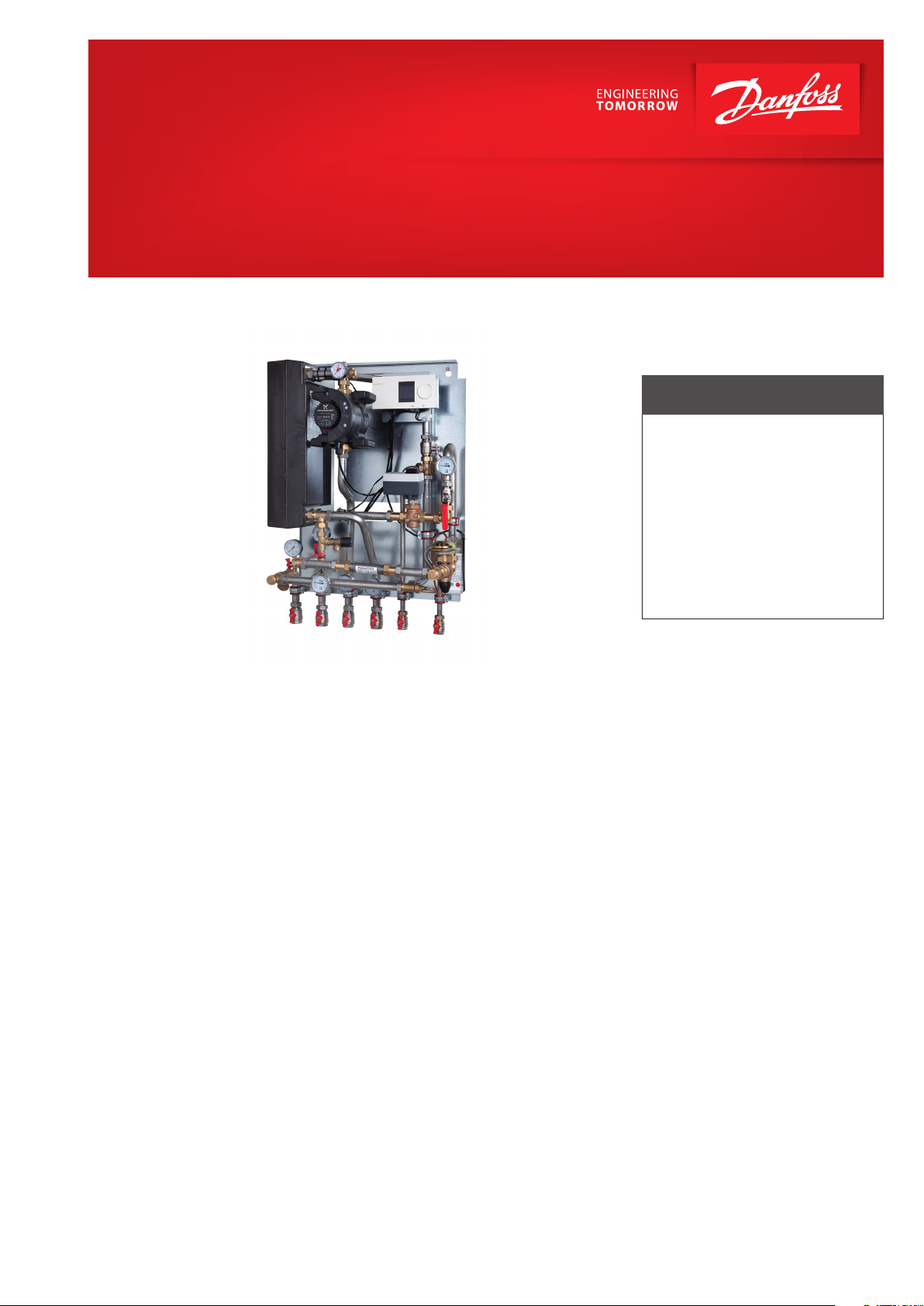
Termix VX-Compact-28-HWP
Indirect substation for apartment buildings with up to 25 apartments
FEATURES AND BENEFITS
• Substation for apartment buildings
• Indirect heating, connections
for domestic hot water tank
• Thermostatic or electronic regulation
of heating (HE) temperature
• Capacity: 35-75 kW heating
• Minimum space required for installation
• Pipes and plate heat exchanger
made of stainless steel
Application
The Termix VX Compact 28 is a complete solution for space heating with
optimal safety, ecient energy transfer, service-friendly construction and
a compact design. The substation is
applicable, if a heat exchanger is required or on a conversion to district
heating, where the existing equipment
is unsuitable for direct connection.
The Termix VX Compact 28 substation
is ideal, where a high level of security
against burst pipes and water damage
in the heating system is required.
District heating (DH)
The district heating circuit is prefabricated with motorized control valve,
dierential pressure controller, thermometers, ball valves, tting piece
and sensor pockets for insertion of
aheat meter.
Heating (HE)
The heating circuit consists of a plate
heat exchanger, safety valve, manometer, thermometers, ball valves, drain
valve, air valve and circulation pump.
The heating temperature can be controlled by the electronic controller
with an outdoor temperature sensor.
Domestic hot water (DHW)
Termix VX Compact 28 is supplied
with connection pipes for a DHW
tank on the supply line.
Options
As an option the substation can be
equipped with a thermostat with
safety monitor. This is possible only
for substations with electronic controller.
Construction
All pipes are made of stainless steel.
The connections are made by nuts
and gaskets. The Termix VX Compact
28 is delivered with a white-lacquered steel cover.
www.danfoss.com
Page 2
Danfoss GmbH Fernwärme- und Regelungstechnik · Carl-Legien-Str. 8 · 63073 Oenbach
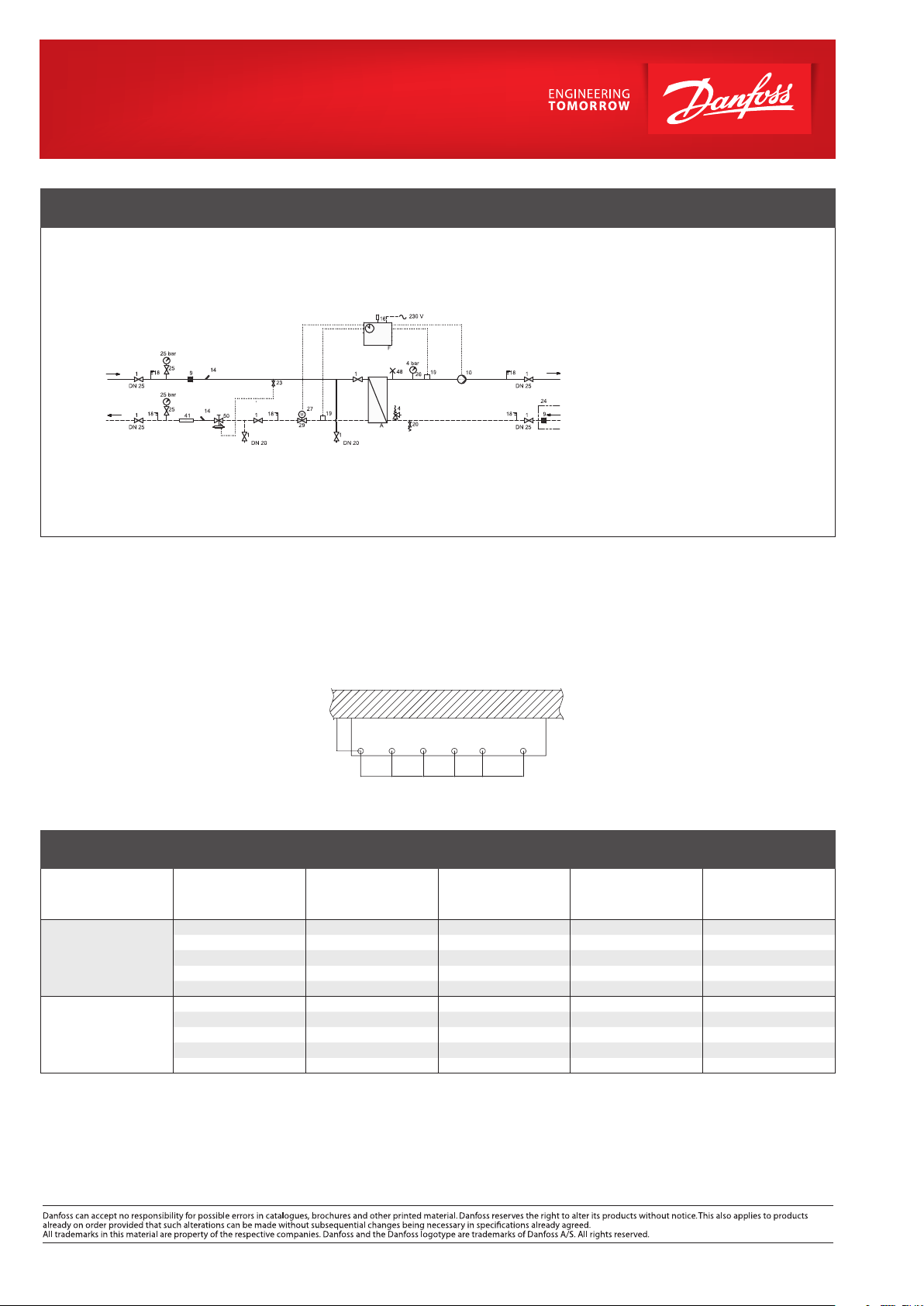
CIRCUIT DIAGRAM – EXAMPLE
DH
supply
DH
return
HE
supply
HE
return
A Plate heat exchanger HE
F Electronic controller
1 Ball valve
4 Safety valve
9 Strainer
10 Circulation pump
14 Sensor pocket, energy meter
16 Outdoor sensor
18 Thermometer
19 Surface sensor
20 Filling/drain valve
23 Ball valve
24 Delivered loose with unit
25 Manometer with ball valve
26 Manometer
27 Actuator
29 2-way motorized valve
41 Fitting piece, energy meter
48 Air escape, manual
50 Di. pressure cont. ow limiter
Technical parameters:
Nominal pressure: PN 16
DH supply temperature: T
Brazing material (HEX): Copper
Weight: approx. 50 kg
Dimensions (mm):
H 940 × W 620 × D 420
Electrical supply: 230 V AC
max
= 120 °C
HEATING: CAPACITY EXAMPLES
Substation
type
Type 1
Type 2
Heating
capacity
[kW]
50 90 / 55 50 / 70
50
35
50
35 80 / 60 55 / 75
75 90 / 55 50 / 70
75 80 / 55 50 / 70
55 75 / 55 50 / 70
75 90 / 60 55 / 75
55 80 / 60 55 / 75
Connections:
1 District heating supply (DH)
2 District heating return (DH)
3 Heating supply (HE)
4 Heating return (HE)
5 Tank supply (DHW)
6 Tank return (DCW)
seen from above
Heating circuit
primary
[°C]
80 / 55 50 / 70
75 / 55 50 / 70
90 / 60 55 / 75
Heating circuit
secondary
[°C]
wall
Connections sizes:
DH: 1” (ext. thread)
HE: 1” (int. thread)
DCW + DHW: ¾” (int. thread)
Options:
• Thermostat with safety monitor
Flow rate
primary
[l / h]
1200 2238
1830 2238
1823 1623
1426 2238
1797 1623
1801 3378
2735 3378
2723 2460
2140 3378
2687 2460
Flow rate
secondary
[l / h]
Technische Beratung/Angebote: Tel.: 069 / 8902 - 960 · Fax: 069 / 8902 466 - 948 · anfrage-fw@danfoss.com
Auftragsabwicklung: Tel.: 069 / 8902 - 970 · Fax: 069 / 8902 466 - 949 · verkauf-fw@danfoss.com
© Danfoss | DHS-SRMT/ PL | 2016 . 04
VL.IE.I2.02
 Loading...