How it Works
Log In / Sign Up
Buy Points
How it Works
FAQ
Contact Us
Questions and Suggestions
Users
Danfoss
Loading...
V
VRG801
VRH 120
5
VRH 30
4
VRH 5
5
VRH 60
4
VS 06
VS 10
VS 2
19
VSB 06-CN
VSB 06-EN
VSB 12-CN
VSB 12-EN
VSH
2
VSH 008
VSH088
13
VSH117
13
VSH170
13
VSH170AGANA
8
VSH scroll compressors with frequency control for air conditioning systems
VSP
VSP 100
VSP 125
VSP 160
VSP 200
VSP 250
VSP 315
VSP 400
VSP 50
VSP 70
VSP 80
VSPP
3
VT2800 Series
VTA 572
VTC 500
VTC 511
VTZ
VVS
VVX
2
VVX-B
5
VVX-B HWP
VVX Compact
VVX Compact 28
7
VVX Compact 28 - 40
VVX-I
2
VVX-ID 22-22
2
VVX-OR
VVX-Q
VX
VX 22
2
VX2 PTC
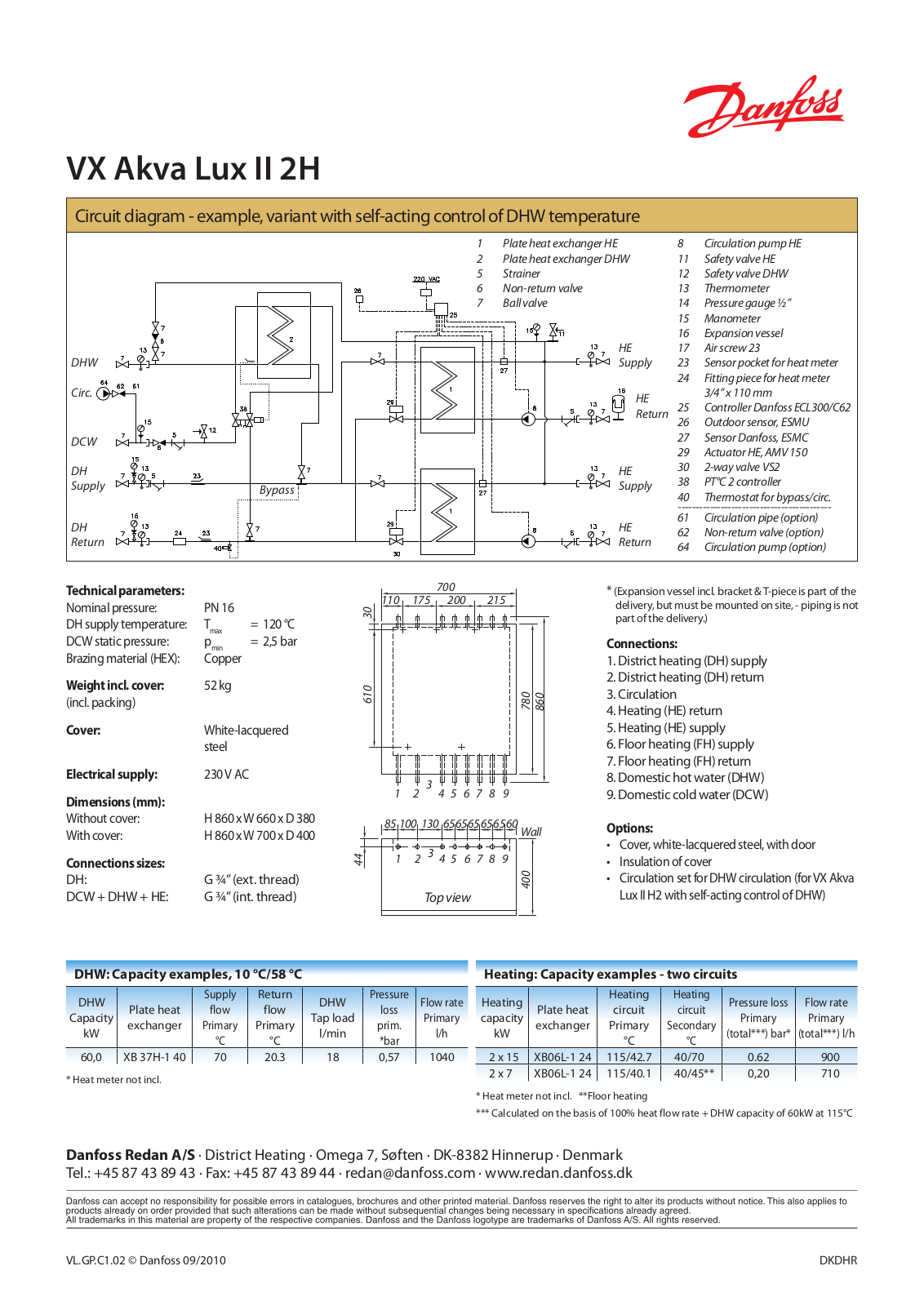
VX Akva Lux II 2H
VX Compact 28
4
VX Compact 28 - 40
2
VX Compact 28 HW OP
2
VX-Compact-28-HWP
4
VX Compact – Floor Station
VXe Solo H
VXe Solo HWP
VXe Solo HWS
VX-F
3
VXi Solo
VXi Solo H
3
VXi Solo HOFOR
VXi Solo HWP
VX SLS
VX SOLO 22
6
VX Solo H OP
VX Solo HWS
2
VX Solo HWS OP
2
VX Solo II
11
VX Solo II H
3
VX Solo II H2
2
VX Solo II H2WP
2
VX Solo II H2WS
2
VX Solo II HOFOR
VX Solo II HWP
2
VX Solo II HWS
2
VX Solo II Kbh
VX Solo II Series
VX Solo OP
VX - T24
VX tengigrind
VX-W
Vykurovacie káble
Vynuogynų apsauga nuo šalčio
VZ2
12
VZ 3
12
VZ 4
12
VZH028-035-044
VZH052-065
VZH088
18
VZH088-117-170
4
VzH088AGANA
VZH117
18
VZH170
18
VzH170AGANA
3
VZH hybrid manifold
VZL 2
13
VZL 3
13
Výmenníkové stanice na centrálne zásobovanie teplom
Loading...
Loading...
Nothing found
VX Akva Lux II 2H
Fact sheet
2 pgs
730.17 Kb
0
Table of contents
Loading...
Danfoss VX Akva Lux II 2H Fact sheet
...
Danfoss Fact sheet
Download
Specifications and Main Features
Frequently Asked Questions
User Manual
Download
Page 1
Page 2
Loading...
+
hidden pages
Unhide
You need points to download manuals.
1 point = 1 manual.
You can buy points or you can get point for every manual you upload.
Buy points
Upload your manuals
 Loading...